EP3155296B1 - Procede de fabrication en moulage et surmoulage d'une roue dentee a jante coulee cannelee - Google Patents
Procede de fabrication en moulage et surmoulage d'une roue dentee a jante coulee cannelee Download PDFInfo
- Publication number
- EP3155296B1 EP3155296B1 EP15733798.1A EP15733798A EP3155296B1 EP 3155296 B1 EP3155296 B1 EP 3155296B1 EP 15733798 A EP15733798 A EP 15733798A EP 3155296 B1 EP3155296 B1 EP 3155296B1
- Authority
- EP
- European Patent Office
- Prior art keywords
- rim
- tubular preform
- recesses
- wheel
- main axis
- Prior art date
- Legal status (The legal status is an assumption and is not a legal conclusion. Google has not performed a legal analysis and makes no representation as to the accuracy of the status listed.)
- Active
Links
Images

Classifications
-
- B—PERFORMING OPERATIONS; TRANSPORTING
- B29—WORKING OF PLASTICS; WORKING OF SUBSTANCES IN A PLASTIC STATE IN GENERAL
- B29C—SHAPING OR JOINING OF PLASTICS; SHAPING OF MATERIAL IN A PLASTIC STATE, NOT OTHERWISE PROVIDED FOR; AFTER-TREATMENT OF THE SHAPED PRODUCTS, e.g. REPAIRING
- B29C39/00—Shaping by casting, i.e. introducing the moulding material into a mould or between confining surfaces without significant moulding pressure; Apparatus therefor
- B29C39/003—Shaping by casting, i.e. introducing the moulding material into a mould or between confining surfaces without significant moulding pressure; Apparatus therefor characterised by the choice of material
- B29C39/006—Monomers or prepolymers
-
- B—PERFORMING OPERATIONS; TRANSPORTING
- B29—WORKING OF PLASTICS; WORKING OF SUBSTANCES IN A PLASTIC STATE IN GENERAL
- B29C—SHAPING OR JOINING OF PLASTICS; SHAPING OF MATERIAL IN A PLASTIC STATE, NOT OTHERWISE PROVIDED FOR; AFTER-TREATMENT OF THE SHAPED PRODUCTS, e.g. REPAIRING
- B29C37/00—Component parts, details, accessories or auxiliary operations, not covered by group B29C33/00 or B29C35/00
- B29C37/0078—Measures or configurations for obtaining anchoring effects in the contact areas between layers
- B29C37/0082—Mechanical anchoring
-
- B—PERFORMING OPERATIONS; TRANSPORTING
- B29—WORKING OF PLASTICS; WORKING OF SUBSTANCES IN A PLASTIC STATE IN GENERAL
- B29C—SHAPING OR JOINING OF PLASTICS; SHAPING OF MATERIAL IN A PLASTIC STATE, NOT OTHERWISE PROVIDED FOR; AFTER-TREATMENT OF THE SHAPED PRODUCTS, e.g. REPAIRING
- B29C45/00—Injection moulding, i.e. forcing the required volume of moulding material through a nozzle into a closed mould; Apparatus therefor
- B29C45/14—Injection moulding, i.e. forcing the required volume of moulding material through a nozzle into a closed mould; Apparatus therefor incorporating preformed parts or layers, e.g. injection moulding around inserts or for coating articles
- B29C45/14065—Positioning or centering articles in the mould
-
- B—PERFORMING OPERATIONS; TRANSPORTING
- B29—WORKING OF PLASTICS; WORKING OF SUBSTANCES IN A PLASTIC STATE IN GENERAL
- B29C—SHAPING OR JOINING OF PLASTICS; SHAPING OF MATERIAL IN A PLASTIC STATE, NOT OTHERWISE PROVIDED FOR; AFTER-TREATMENT OF THE SHAPED PRODUCTS, e.g. REPAIRING
- B29C45/00—Injection moulding, i.e. forcing the required volume of moulding material through a nozzle into a closed mould; Apparatus therefor
- B29C45/14—Injection moulding, i.e. forcing the required volume of moulding material through a nozzle into a closed mould; Apparatus therefor incorporating preformed parts or layers, e.g. injection moulding around inserts or for coating articles
- B29C45/1418—Injection moulding, i.e. forcing the required volume of moulding material through a nozzle into a closed mould; Apparatus therefor incorporating preformed parts or layers, e.g. injection moulding around inserts or for coating articles the inserts being deformed or preformed, e.g. by the injection pressure
- B29C45/14221—Injection moulding, i.e. forcing the required volume of moulding material through a nozzle into a closed mould; Apparatus therefor incorporating preformed parts or layers, e.g. injection moulding around inserts or for coating articles the inserts being deformed or preformed, e.g. by the injection pressure by tools, e.g. cutting means
-
- B—PERFORMING OPERATIONS; TRANSPORTING
- B29—WORKING OF PLASTICS; WORKING OF SUBSTANCES IN A PLASTIC STATE IN GENERAL
- B29C—SHAPING OR JOINING OF PLASTICS; SHAPING OF MATERIAL IN A PLASTIC STATE, NOT OTHERWISE PROVIDED FOR; AFTER-TREATMENT OF THE SHAPED PRODUCTS, e.g. REPAIRING
- B29C45/00—Injection moulding, i.e. forcing the required volume of moulding material through a nozzle into a closed mould; Apparatus therefor
- B29C45/14—Injection moulding, i.e. forcing the required volume of moulding material through a nozzle into a closed mould; Apparatus therefor incorporating preformed parts or layers, e.g. injection moulding around inserts or for coating articles
- B29C45/1459—Coating annular articles
-
- B—PERFORMING OPERATIONS; TRANSPORTING
- B29—WORKING OF PLASTICS; WORKING OF SUBSTANCES IN A PLASTIC STATE IN GENERAL
- B29C—SHAPING OR JOINING OF PLASTICS; SHAPING OF MATERIAL IN A PLASTIC STATE, NOT OTHERWISE PROVIDED FOR; AFTER-TREATMENT OF THE SHAPED PRODUCTS, e.g. REPAIRING
- B29C45/00—Injection moulding, i.e. forcing the required volume of moulding material through a nozzle into a closed mould; Apparatus therefor
- B29C45/16—Making multilayered or multicoloured articles
- B29C45/1615—The materials being injected at different moulding stations
-
- B—PERFORMING OPERATIONS; TRANSPORTING
- B29—WORKING OF PLASTICS; WORKING OF SUBSTANCES IN A PLASTIC STATE IN GENERAL
- B29C—SHAPING OR JOINING OF PLASTICS; SHAPING OF MATERIAL IN A PLASTIC STATE, NOT OTHERWISE PROVIDED FOR; AFTER-TREATMENT OF THE SHAPED PRODUCTS, e.g. REPAIRING
- B29C67/00—Shaping techniques not covered by groups B29C39/00 - B29C65/00, B29C70/00 or B29C73/00
- B29C67/24—Shaping techniques not covered by groups B29C39/00 - B29C65/00, B29C70/00 or B29C73/00 characterised by the choice of material
- B29C67/246—Moulding high reactive monomers or prepolymers, e.g. by reaction injection moulding [RIM], liquid injection moulding [LIM]
-
- B—PERFORMING OPERATIONS; TRANSPORTING
- B29—WORKING OF PLASTICS; WORKING OF SUBSTANCES IN A PLASTIC STATE IN GENERAL
- B29K—INDEXING SCHEME ASSOCIATED WITH SUBCLASSES B29B, B29C OR B29D, RELATING TO MOULDING MATERIALS OR TO MATERIALS FOR MOULDS, REINFORCEMENTS, FILLERS OR PREFORMED PARTS, e.g. INSERTS
- B29K2077/00—Use of PA, i.e. polyamides, e.g. polyesteramides or derivatives thereof, as moulding material
- B29K2077/10—Aromatic polyamides [polyaramides] or derivatives thereof
-
- B—PERFORMING OPERATIONS; TRANSPORTING
- B29—WORKING OF PLASTICS; WORKING OF SUBSTANCES IN A PLASTIC STATE IN GENERAL
- B29L—INDEXING SCHEME ASSOCIATED WITH SUBCLASS B29C, RELATING TO PARTICULAR ARTICLES
- B29L2015/00—Gear wheels or similar articles with grooves or projections, e.g. control knobs
-
- B—PERFORMING OPERATIONS; TRANSPORTING
- B62—LAND VEHICLES FOR TRAVELLING OTHERWISE THAN ON RAILS
- B62D—MOTOR VEHICLES; TRAILERS
- B62D5/00—Power-assisted or power-driven steering
- B62D5/008—Changing the transfer ratio between the steering wheel and the steering gear by variable supply of energy, e.g. by using a superposition gear
-
- F—MECHANICAL ENGINEERING; LIGHTING; HEATING; WEAPONS; BLASTING
- F16—ENGINEERING ELEMENTS AND UNITS; GENERAL MEASURES FOR PRODUCING AND MAINTAINING EFFECTIVE FUNCTIONING OF MACHINES OR INSTALLATIONS; THERMAL INSULATION IN GENERAL
- F16H—GEARING
- F16H55/00—Elements with teeth or friction surfaces for conveying motion; Worms, pulleys or sheaves for gearing mechanisms
- F16H55/02—Toothed members; Worms
- F16H55/06—Use of materials; Use of treatments of toothed members or worms to affect their intrinsic material properties
- F16H2055/065—Moulded gears, e.g. inserts therefor
Definitions
- the present invention relates to the general field of the manufacture of wheels intended to ensure the transmission of a torque within a mechanism, and more particularly the field of manufacture of gear wheels for gear type mechanisms.
- the present invention relates more particularly to the manufacture of gear wheels for power steering reducers for motor vehicles.
- the polymer material may be exposed to shearing and self-heating effects at its injection point, which cause the polymer chains to be cut off, so that the rim finally obtained may not have a mechanical strength, including tenacity, optimal.
- the overmoulding operation of the rim may require, especially in order to limit the aforementioned shearing effects, pouring descents of particularly large volume, which leads to an overconsumption of raw material and energy.
- the objects assigned to the invention therefore aim at overcoming the aforementioned drawbacks and at proposing a new manufacturing process for wheel, and in particular a toothed wheel, which makes it possible to obtain in a simple, fast and inexpensive way a wheel which is both light and particularly robust.
- a method of manufacturing a wheel comprising a step (a) for manufacturing a tubular preform, during which a liquid is poured into a first mold to be polymerized and said liquid is polymerized in said first mold so as to solidify it into a tubular preform, with a directing axis (XX '), the first mold comprising a central core, which is centered on the directing axis (XX') and which allows forming the central bore of the tubular preform, as well as modeling cores arranged substantially parallel to the director axis (XX ') so as to provide in the radial thickness of the tubular preform recesses which extend axially according to the length of said tubular preform, said method then comprising a step (b) of debiting, during which the tubular preform is fed substantially perpendicularly to its director axis (XX '), and in such a way that recess to the recesses, so as to obtain a
- the production of a tubular preform by casting by introducing into the first mold the precursor or precursors of the polymeric material intended to constitute said preform (and thus the rims issuing from said preform), the polymer chains are created directly in the first mold, without malmenerating them and in particular without exposing them to significant heating or shear stresses.
- the tubular preform, and consequently the rims that are drawn from it, are therefore made of a long-chain polymer, with preserved integrity, which gives them excellent mechanical strength, and in particular good toughness.
- the preparation in one piece of a tubular preform in which one can cut several rims allows (pre) manufacture said rims in batches, in a single casting, which saves time and energy.
- a tubular preform can be used to produce rims of different heights, which makes the process particularly versatile, although standardized for the casting of the tubular preform.
- the production of a plurality of recesses according to the invention from the initial molding of the tubular preform to the stage of step (a), makes it possible to preform the rim, simply and rapidly, by means of modeling cores of relatively simple shape and easily demoldable (and therefore by means of a first mold relatively simple to manufacture and implement), hooking reliefs which will then allow effective fixing of said rim on the wheel when step (c) overmoulding, hooking reliefs which will ensure in particular a good resistance to torsional torques.
- the use of a junction by an intermediate overmolded disc makes it possible, if necessary, to differentiate the first constituent polymer material from the rim of the second polymeric (filling) material constituting the intermediate disc, and thus to adapt the mechanical properties of the wheel according to its destination.
- an intermediate disk forming a particularly rigid infrastructure for example a composite material comprising a polymer matrix containing reinforcing fibers, of the glass fiber, carbon, or aramid type, with a relatively thick rim ( plus) flexible, made for example in a non-fiber polymer material, so as to improve the quality of meshing and distribution within the wheel forces transmitted by the mechanism which said wheel is integrated.
- the present invention relates to a method of manufacturing a wheel 1, and more particularly to a gear wheel 1.
- Said toothed wheel 1 may in particular be a geared gear wheel, and more particularly, as illustrated in FIG. figure 7 , a gear wheel for power steering.
- the wheel 1 may for example form a tangent wheel to be driven by a worm.
- the toothed wheel 1 may have any type of meshing teeth 2 (not detailed in the figures), for example forming a straight toothing, a helical toothing, or a herringbone toothing.
- the wheel 1 will advantageously be fixed to a shaft 3, preferably metal, which materializes the axis of rotation (X 1 , X 1 ') of said wheel.
- Said shaft 3 will preferably comprise, for example at one of its ends, a pinion allowing it to engage with another toothed part, such as a steering column or a rack.
- the invention is not limited to a wheel 1 of particular dimensions, it will be noted that, in particular in the context of a wheel 1 intended for a power steering gearbox, the overall diameter D1 of said wheel 1 may be substantially between 3 cm and 20 cm, more particularly between 5 cm and 15 cm, and preferably equal to 10 cm.
- the process comprises a step (a) of manufacturing a tubular preform 4, during which a liquid is poured into a first mold 5 to polymerize and polymerizes said liquid in said first mold 5 so as to solidify it into a tubular preform 4, with a directing axis (XX '), as illustrated in FIG. figure 1 .
- the casting of the tubular preform 4 according to the invention amounts to placing in the first mold 5 a bath containing the precursor (s) of the (first) polymeric material constituting the tubular preform, so that the polymerization, that is to say the constitution of the polymer chains of said first material, is carried out directly within the first mold 5, without particular shear stresses.
- the first polymeric material constituting the tubular preform 4 can thus be obtained by synthesizing large, particularly strong polymer chains.
- the first mold 5 comprises a central core 6, which is centered on the directing axis (XX ') and which makes it possible to form the central bore 7 of the tubular preform, as well as modeling cores 8 arranged substantially parallel to the directing axis (XX ') so as to provide in the radial thickness E4 of the tubular preform 4 recesses 9 which extend axially along the length L4 of said tubular preform 4.
- the method thus makes it possible to directly form, during the synthesis of the constituent polymeric material of the tubular preform 4, the recesses 9 which serve to reinforce the resistance, in particular in torsion, of the rim on the hub of the wheel, the cores modeling device 8 for reserving the spaces corresponding to said recesses 9.
- the large polymer chains obtained by casting can be synthesized directly around (and in contact with) the cores (of the central core 6 and, especially, modeling nuclei 8), so that said chains can follow the shapes of said nuclei 6, 8 without interrupting.
- tubular preform 4 and consequently the rim 10 which will be drawn from it, will advantageously have a particularly robust, relatively homogeneous structure, and not subject to stress concentrations or to failure primers, even in the immediate vicinity of the recesses. 9.
- the shaping cores 8 (as well as the central core 6) will be substantially rectilinear, at the angles of clearance, and aligned parallel to the director axis (XX '), so as to allow easy axial demolding of the preform tubular 4.
- modeling cores 8 (and the central core 6) will preferably extend over the majority of the length L4 of the tubular preform 4, and preferably over the entire length L4 of the tubular preform 4, so that the recesses 9, and more particularly each recess 9, crosses (s) axially the tubular preform 4 from one side to the other, continuously.
- the method then comprises, after the step (a) of manufacturing the tubular preform 4, a step (b) of debiting, during which it is debited, for example by sawing or cutting the jet of water, the tubular preform 4 substantially perpendicular to its director axis (XX '), and secantly to the recesses 9, as shown in dashed line on the figure 1 , so as to obtain a tubular preform section forming a rim 10, as illustrated on the Figures 1 to 3 .
- tubular preform 4 will advantageously form a blank that can be cut into several annular slices, each of which will be used to form a rim 10.
- the length L4 of the tubular preform 4 advantageously makes it possible to obtain at least two, at least three, at least five or even at least ten or twenty rims 10, and for example between twenty and forty rims. from a single tubular preform 4.
- the length L4 of the tubular preform 4 will preferably be greater, and for example twice to three times (or even four times) greater, than the overall diameter D4 of said preform 4 (which preferably corresponds substantially to the diameter overall D10 of the rim, and to the diameter D1 of the finished wheel 1).
- the length L4 of the rough preform 4 (exploitable, that is to say comprising recesses 9), may be substantially between 20 cm and 50 cm, and for example of the order of 40 cm, while that the unit (axial) height H10 of the rim 10 may be between 10 mm and 20 mm (which will allow, in the case of a preform of 40 cm, to respectively deliver 20 to 40 rims 10).
- the operation of cutting the rim is likely to interrupt polymer chains at the level of the cutting planes, that is to say at the upper edges 10S and lower 10I of the rim 10 created by the cutting tool, and so that said debiting operation does not affect the length of the deep polymer chains located in the mass of the rim 10 or on the other surfaces of the latter, and in particular the length of the polymer chains delimiting the contours of the recesses 9.
- the resulting rim 10 is and therefore remains particularly strong.
- the method according to the invention then comprises, as illustrated on the Figures 5 and 6 , an overmoulding step (d) in which the rim 10 is placed in a second mold 11 ( figure 5 ), concentrically to a central support member 12, 3, such as a sleeve 12 or (directly) a shaft 3, which materializes the axis of rotation (X 1 , X 1 ') of the wheel 1 to form and injecting, in the interstitial space 13 which is radially between said central support member 12, 3 and the rim 10, a polymeric filler material so that said filler wets said central support member 12 , 3 and enters the recesses 9 of the rim 10, and thus creates, when solidified, an intermediate disc 14 ( Figures 6 and 7 ) which secures the rim 10 to the central support member 12, 3.
- a central support member 12, 3 such as a sleeve 12 or (directly) a shaft 3
- a central support member 12 such as a sleeve 12 or (direct
- the (second) polymeric material used as a filler material to form the intermediate disc 14 will be a thermoplastic polymer, allowing hot injection overmoulding, at a temperature above room temperature.
- the intermediate disc 14 will advantageously form both a hub and the spokes of the wheel 1.
- the intermediate disc 14 may comprise on the one hand a substantially cylindrical hub 17 which envelopes the central support member 12, 3, and on the other hand a flange 15, preferably solid, and preferably substantially normal to the axis of rotation (X 1 , X 1 ') of the wheel, which forms a bridge which connects the radially outer surface of the central support member 12, 3, and more particularly the hub 17 (with which said collar 15 has come so) on the radially inner surface of the rim 10.
- the flange 15 will thus materialize the equivalent of the spokes of the wheel 1.
- the flange 15 may advantageously be reinforced by ribs 16, preferably oriented substantially radially, as illustrated in FIGS. Figures 6 and 7 .
- the flange 15 may preferably comprise reinforcing ribs 16 on its (axially) lower face, or even exclusively on said lower face, as illustrated in FIG. figure 7 .
- the flange 15 has ribs 16 of reinforcement on its face (axially) upper, or on both sides, upper and lower.
- the radial extent R14 of the intermediate disk 14 (which preferably corresponds to the radial extent of the interstitial space 13), considered between the steering axis (XX ') and the rim 10, will represent at least 20%, preferably at least 30% or even at least 40%, and for example between 40% and 70% even 80% of the radius D1 / 2 of the wheel 1.
- the diameter of the central support member 12, 3 may in turn represent less than 50%, and for example between 20% and 35% of the diameter D1 of the wheel 1.
- the central support member may be formed by a sleeve 12, preferably metal, which is advantageously intended to be threaded onto a shaft 3, and fixed on said shaft, for example by fitting, as is illustrated on the Figures 5 to 7 .
- the central support member will be formed directly by the shaft 3, preferably metal, of the wheel 1, the overmolding step (d) then taking place directly on said shaft 3, so that the intermediate disk 14 comes to wet, and hook directly to the surface of said shaft 3.
- the shaft 3 for the sleeve 12 on the Figures 5 to 7 .
- the axis of rotation (X 1 , X 1 ') of the wheel 1 is in practice coincident with the steering axis (XX') of the rim 10, and therefore of the tubular preform 4, such as that this is especially visible on the figure 6 .
- axial a direction or a dimension considered along the axis direction (XX '), respectively (X 1 , X 1 '), or parallel thereto, and by "radial” a direction or a dimension considered transversely, and more particularly perpendicularly, to said director axis (XX '), (X 1 , X 1 ').
- the method comprises a step (e) of cutting meshing teeth, subsequent to the step (d) overmolding, during which one size meshing teeth 2 in the radial thickness of the rim 10 (here corresponding to the radial thickness E4 of the tubular preform 4).
- modeling cores 8 which are formed in one piece with the central core 6, so that the corresponding recesses 9 take the form grooves 20 made in the radially inner surface of the tubular preform 4, and which open radially on the central bore 7 of said tubular preform 4.
- This variant of implementation will advantageously simplify casting tooling, thanks to the use of a single, monolithic core, which will group the central core 6 and integrated modeling cores 8, carried by said central core 6, modeling cores 8 which will thus form male impressions radially projecting on said central core 6.
- the rim 10 thus obtained will therefore have recesses 9 of the indentation type, preferably evenly distributed in a star around the steering axis (XX '), which will serve as hooking reliefs in torsion.
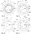
- the penetration profile of the recesses 9, considered in a plane of section normal to the directional axis (XX '), may especially be of the triangular "tip" type ( Figures 8 and 9 ), obtained by broken lines which meet at a vertex forming the most penetrating point in the thickness E4 of the rim 10, or even of the "arch" type, the bottom of each recess 9 being delimited by a curved line forming bowl ( figure 10 ).
- the radial penetration depth E20 of the splines 20 may be between 0.5 mm and 3 mm and / or between 0.5% and 3% of the overall diameter D10 of the rim 10.
- the recesses 9 are thus formed by cylindrical passages, preferably of circular base, of the through-hole type, drilled offset from the central bore 7 (here according to a distribution circle of diameter greater than that of the bore 7), such that said channels 22 are radially separated from said bore 7 by a portion of the radial thickness E4 of the tubular preform 4 (and thus of the rim 10).
- Such a configuration will in particular also strengthen the axial anchoring of the rim 10 on the intermediate disk 14, in addition to the torsion lock.
- the method comprises, after the step (b) of debiting and before the step (d) of overmolding, a step (c) of circular grooving in the course of which is produced on the axially upper edge 10S and / or on the axially lower edge 10I of the rim 10 a circular groove 23, respectively 24, centered on the director axis (XX ') and secant to the recesses 9, such that is illustrated on the figure 4 .
- the digging of the circular groove (s) 23, 24 can advantageously be carried out in a simple and fast manner by removal of material, according to an axial penetration movement, by means of a cutting tool, such as a cutter or bit (bell saw ) of suitable diameter.
- a cutting tool such as a cutter or bit (bell saw ) of suitable diameter.
- the circular groove or grooves 23, 24 will complete and improve the initial shape of the recesses 9 so as to give the latter a radial attachment capacity.
- each circular groove 23, 24 will preferably connect the different recesses 9 to each other, thus forming a circular communication channel (making said recesses communicate with each other), hollowed out in the axial height H10 of the rim, centered on the direction axis (XX '), and located radially beyond the limit of the internal bore 7.
- the circular groove or grooves 23, 24 are preferably contained radially beyond the radially internal limit of the rim 10 (limit of the internal bore 7), so as to form in the rim 10, in transverse section containing the director axis (XX '), strangulated hooking reliefs 25, such as dovetails, which improve the radial anchoring of the intermediate disk 14 to the rim 10 (and vice versa), as this is especially visible on the Figures 4 to 7 .
- the grooves 23, 24 define in fact in the rim 10 a neck-like constriction, axially narrower than the "head” radially internal of said rim 10 which delimits the internal bore 7, which allows the intermediate disc 14 to act as a retaining jaw (here in "C") against the rim 10.
- the invention makes it possible to create, in a few relatively simple and fast operations, double attachment reliefs allowing a share an anchoring in torsion (rotation) thanks to the penetration of the recesses 9 beyond the radially inner envelope of the internal bore 7, and secondly a radial anchoring (in particular centrifugal) thanks to the grooves of strapping 23, 24 (in addition, if necessary, the radial anchorage which may already be provided in a configuration according to which the filling material passes through the closed channels 22, and thus exerts a radial retention against the thickness of the residual rim 10 between the internal bore 7 and said closed channels 22).
- step (c) grooving may be accompanied by the realization of a countersink 26 for axially digging a depression from the edge 10S, 10I of the rim 10, as visible on the Figures 4 and 5 .
- the (first) constituent material of the tubular preform 4, and therefore of the rim 10 will be a polyamide, preferably polyamide 6.
- Such a material combines mechanical and chemical resistance (especially with respect to lubricants) with a certain flexibility that will be useful to the quality of engagement of the teeth 2 with the rest of the mechanism in which the wheel 1 is integrated.
- the invention further relates of course as a wheel 1, and in particular a gear wheel gear, obtained according to the method described above.
Landscapes
- Engineering & Computer Science (AREA)
- Mechanical Engineering (AREA)
- Manufacturing & Machinery (AREA)
- Gears, Cams (AREA)
- Moulds For Moulding Plastics Or The Like (AREA)
- Casting Or Compression Moulding Of Plastics Or The Like (AREA)
Priority Applications (1)
| Application Number | Priority Date | Filing Date | Title |
|---|---|---|---|
| PL15733798T PL3155296T3 (pl) | 2014-06-11 | 2015-06-04 | Sposób wytwarzania przez formowanie i formowanie z obtrysku koła zębatego z odlewaną rowkowaną obręczą |
Applications Claiming Priority (2)
| Application Number | Priority Date | Filing Date | Title |
|---|---|---|---|
| FR1455300A FR3022172B1 (fr) | 2014-06-11 | 2014-06-11 | Procede de fabrication d’une roue dentee a jante coulee cannelee |
| PCT/FR2015/051481 WO2015189502A1 (fr) | 2014-06-11 | 2015-06-04 | Procédé de fabrication d'une roue dentée à jante coulée cannelée |
Publications (2)
| Publication Number | Publication Date |
|---|---|
| EP3155296A1 EP3155296A1 (fr) | 2017-04-19 |
| EP3155296B1 true EP3155296B1 (fr) | 2018-04-04 |
Family
ID=51168282
Family Applications (1)
| Application Number | Title | Priority Date | Filing Date |
|---|---|---|---|
| EP15733798.1A Active EP3155296B1 (fr) | 2014-06-11 | 2015-06-04 | Procede de fabrication en moulage et surmoulage d'une roue dentee a jante coulee cannelee |
Country Status (8)
| Country | Link |
|---|---|
| US (1) | US10513059B2 (pl) |
| EP (1) | EP3155296B1 (pl) |
| JP (1) | JP6605509B2 (pl) |
| CN (1) | CN106573398B (pl) |
| BR (1) | BR112016029023A2 (pl) |
| FR (1) | FR3022172B1 (pl) |
| PL (1) | PL3155296T3 (pl) |
| WO (1) | WO2015189502A1 (pl) |
Families Citing this family (7)
| Publication number | Priority date | Publication date | Assignee | Title |
|---|---|---|---|---|
| JP6632921B2 (ja) * | 2016-03-23 | 2020-01-22 | 株式会社エンプラス | 樹脂製歯車、樹脂製歯車の射出成形方法、樹脂製歯付きベルト用プーリ、及び樹脂製回転体 |
| EP3459706B1 (de) * | 2017-09-25 | 2023-08-30 | IMS Gear SE & Co. KGaA | Stirnrad zur verwendung in einem stirnradgetriebe, zahnradpaarung für ein stirnradgetriebe, stirnradgetriebe mit einer derartigen zahnradpaarung sowie verfahren zum herstellen eines stirnrads |
| ES2906056T3 (es) * | 2019-02-28 | 2022-04-13 | Ims Gear Se & Co Kgaa | Pieza de soporte de corona dentada para una rueda dentada de dos o múltiples componentes, así como rueda dentada de dos o múltiples componentes con una pieza de soporte de corona dentada de este tipo |
| FR3098483B1 (fr) | 2019-07-12 | 2021-06-18 | Jtekt Europe Sas | Système de direction assistée avec une colonne de direction rétractable selon une course de recul améliorée au moyen d’un capteur inductif traversant |
| FR3098482B1 (fr) | 2019-07-12 | 2021-06-18 | Jtekt Europe Sas | Système de direction assistée avec une colonne de direction rétractable selon une course de recul améliorée au moyen d’une cible inférieure, pour dispositif de mesure d’angle, intégrée à une roue tangente de réducteur |
| CN111059253A (zh) * | 2019-12-23 | 2020-04-24 | 深圳市华南新海传动机械有限公司 | 一种齿轮 |
| JP7787639B2 (ja) * | 2020-05-18 | 2025-12-17 | 住友重機械工業株式会社 | 歯車の製造方法、歯車及び撓み噛合い式歯車装置 |
Citations (10)
| Publication number | Priority date | Publication date | Assignee | Title |
|---|---|---|---|---|
| US3114598A (en) | 1952-10-09 | 1963-12-17 | Continental Gummi Werke Ag | Method of making a precision transmission belt with meshing teeth |
| GB1113945A (en) | 1964-06-15 | 1968-05-15 | Pneumatiques Caoutchouc Mfg | Improvements in or relating to continuous toothed belts |
| US3412632A (en) | 1966-09-23 | 1968-11-26 | Pitney Bowes Inc | Differential mechanism |
| US4337672A (en) | 1980-05-15 | 1982-07-06 | Samuel Shiber | Speed changing floating power transmission ring |
| DE10127224A1 (de) | 2001-05-28 | 2002-12-12 | Ensinger Kunststofftechnologie | Zahnrad |
| JP2004204902A (ja) | 2002-12-24 | 2004-07-22 | Nsk Ltd | ウォームホイールおよびその製造方法 |
| US20060027294A1 (en) | 2000-09-11 | 2006-02-09 | The Dow Chemical Company | Run flat tire support and filament formed reinforcement member therefor |
| EP1777439A1 (de) | 2005-10-19 | 2007-04-25 | IMS Gear GmbH | Zahnrad und Verfahren zum Herstellen eines Zahnrads |
| US20070214642A1 (en) | 2004-04-16 | 2007-09-20 | Jawk Meijer | Electronic Power Assist Steering Worm Gears |
| DE102012102775A1 (de) | 2012-03-30 | 2013-10-02 | Zf Lenksysteme Gmbh | Schraubrad für eine elektromechanische lenkvorrichtung |
Family Cites Families (8)
| Publication number | Priority date | Publication date | Assignee | Title |
|---|---|---|---|---|
| SE427913B (sv) * | 1981-04-14 | 1983-05-24 | Cougar Sa | Forfarande jemte anordning for framstellning av en for fordon eller liknande avsedd hjulkonstruktion av plastmaterial |
| JPS58128563A (ja) * | 1982-01-25 | 1983-08-01 | Daihatsu Motor Co Ltd | エンジンにおける樹脂製ギヤ |
| JPH0989081A (ja) * | 1995-09-28 | 1997-03-31 | Fuji Heavy Ind Ltd | 汎用エンジンの射出成形ギヤ及びその製造方法 |
| JP2003118006A (ja) * | 2001-10-10 | 2003-04-23 | Showa Seiko Kk | 熱可塑性樹脂成形物に金属ボスを固定する方法 |
| JP2003207029A (ja) * | 2002-01-11 | 2003-07-25 | Koyo Seiko Co Ltd | 減速歯車機構及び電動式パワーステアリング装置 |
| FR2853373B1 (fr) * | 2003-04-02 | 2006-03-03 | Hutchinson | Element de decouplage en materiau deformable dans un systeme de transmission de puissance |
| JP5562532B2 (ja) * | 2008-07-07 | 2014-07-30 | 日本精工株式会社 | 電動パワーステアリング装置のウォームホイール、電動パワーステアリング装置 |
| KR20130100411A (ko) * | 2012-03-02 | 2013-09-11 | 주식회사 만도 | 전동식 동력 보조 조향장치의 웜휠 및 그 제조방법 |
-
2014
- 2014-06-11 FR FR1455300A patent/FR3022172B1/fr active Active
-
2015
- 2015-06-04 BR BR112016029023A patent/BR112016029023A2/pt not_active Application Discontinuation
- 2015-06-04 WO PCT/FR2015/051481 patent/WO2015189502A1/fr not_active Ceased
- 2015-06-04 CN CN201580031453.3A patent/CN106573398B/zh active Active
- 2015-06-04 EP EP15733798.1A patent/EP3155296B1/fr active Active
- 2015-06-04 PL PL15733798T patent/PL3155296T3/pl unknown
- 2015-06-04 US US15/313,602 patent/US10513059B2/en active Active
- 2015-06-04 JP JP2016572247A patent/JP6605509B2/ja active Active
Patent Citations (10)
| Publication number | Priority date | Publication date | Assignee | Title |
|---|---|---|---|---|
| US3114598A (en) | 1952-10-09 | 1963-12-17 | Continental Gummi Werke Ag | Method of making a precision transmission belt with meshing teeth |
| GB1113945A (en) | 1964-06-15 | 1968-05-15 | Pneumatiques Caoutchouc Mfg | Improvements in or relating to continuous toothed belts |
| US3412632A (en) | 1966-09-23 | 1968-11-26 | Pitney Bowes Inc | Differential mechanism |
| US4337672A (en) | 1980-05-15 | 1982-07-06 | Samuel Shiber | Speed changing floating power transmission ring |
| US20060027294A1 (en) | 2000-09-11 | 2006-02-09 | The Dow Chemical Company | Run flat tire support and filament formed reinforcement member therefor |
| DE10127224A1 (de) | 2001-05-28 | 2002-12-12 | Ensinger Kunststofftechnologie | Zahnrad |
| JP2004204902A (ja) | 2002-12-24 | 2004-07-22 | Nsk Ltd | ウォームホイールおよびその製造方法 |
| US20070214642A1 (en) | 2004-04-16 | 2007-09-20 | Jawk Meijer | Electronic Power Assist Steering Worm Gears |
| EP1777439A1 (de) | 2005-10-19 | 2007-04-25 | IMS Gear GmbH | Zahnrad und Verfahren zum Herstellen eines Zahnrads |
| DE102012102775A1 (de) | 2012-03-30 | 2013-10-02 | Zf Lenksysteme Gmbh | Schraubrad für eine elektromechanische lenkvorrichtung |
Also Published As
| Publication number | Publication date |
|---|---|
| US10513059B2 (en) | 2019-12-24 |
| JP6605509B2 (ja) | 2019-11-13 |
| CN106573398A (zh) | 2017-04-19 |
| JP2017520729A (ja) | 2017-07-27 |
| FR3022172A1 (fr) | 2015-12-18 |
| CN106573398B (zh) | 2019-01-29 |
| FR3022172B1 (fr) | 2016-05-27 |
| US20170095950A1 (en) | 2017-04-06 |
| EP3155296A1 (fr) | 2017-04-19 |
| WO2015189502A1 (fr) | 2015-12-17 |
| PL3155296T3 (pl) | 2018-09-28 |
| BR112016029023A2 (pt) | 2017-08-22 |
Similar Documents
| Publication | Publication Date | Title |
|---|---|---|
| EP3155296B1 (fr) | Procede de fabrication en moulage et surmoulage d'une roue dentee a jante coulee cannelee | |
| EP3134246B1 (fr) | Procédé de fabrication d'une roue dentée allégée par surmoulage double | |
| EP2483566B1 (fr) | Helice, dispositif de refroidissement moteur comprenant une telle helice et moule de fabrication de ladite helice | |
| EP2082958B1 (fr) | Pale de giravion munie d'un longeron intégrant une attache de fixation, et procédé de fabrication d'un tel longeron | |
| EP2245205B1 (fr) | Procede de fabrication d'une piece metallique renforcee de fibres ceramiques | |
| EP0442238B1 (fr) | Outil de coupe circulaire et rotatif composite | |
| FR2765649A1 (fr) | Procede de fabrication d'un engrenage rotatif en matiere thermoplastique et engrenage ainsi obtenu | |
| EP2512706B1 (fr) | Procede de fabrication, par metallurgie des poudres, d'une couronne a crabots | |
| EP2952321B1 (fr) | Procédé de surmoulage d'une roue dentée avec piégeage de la goutte froide | |
| EP3038791B1 (fr) | Procédé de fabrication d'un bord de renforcement d'aube | |
| WO2015185817A1 (fr) | Procédé de fabrication de roue dentée avec cerclage de renfort | |
| EP1798429B1 (fr) | Bielle a tube en un materiau composite et procede de fabrication d'une telle bielle | |
| EP2641749B1 (fr) | Jante, son procédé de fabrication et roue de cycle | |
| FR3122112A1 (fr) | Procédé de fabrication par injection-compression d’une roue dentée | |
| WO2015090987A1 (fr) | Traverse pour planche de bord avec support latéral a structure mixte métallo-plastique | |
| CA2543850A1 (fr) | Procede de fabrication de pieces en matiere synthetique a section annulaire creuse et piece ainsi obtenue | |
| FR3062337A1 (fr) | Procede de fabrication d’une roue a denture globique comprenant un moulage partiel de la denture suivi d’une etape d’usinage d’un fond de denture concave | |
| FR2778624A1 (fr) | Assemblage d'un pivot de fourche de bicyclette et d'une tete de fourche, procede de realisation de l'assemblage, et fourche le comportant | |
| EP2014954A2 (fr) | Différentiel de transmission et utilisation d'un tel différentiel |
Legal Events
| Date | Code | Title | Description |
|---|---|---|---|
| STAA | Information on the status of an ep patent application or granted ep patent |
Free format text: STATUS: THE INTERNATIONAL PUBLICATION HAS BEEN MADE |
|
| PUAI | Public reference made under article 153(3) epc to a published international application that has entered the european phase |
Free format text: ORIGINAL CODE: 0009012 |
|
| STAA | Information on the status of an ep patent application or granted ep patent |
Free format text: STATUS: REQUEST FOR EXAMINATION WAS MADE |
|
| 17P | Request for examination filed |
Effective date: 20170106 |
|
| AK | Designated contracting states |
Kind code of ref document: A1 Designated state(s): AL AT BE BG CH CY CZ DE DK EE ES FI FR GB GR HR HU IE IS IT LI LT LU LV MC MK MT NL NO PL PT RO RS SE SI SK SM TR |
|
| AX | Request for extension of the european patent |
Extension state: BA ME |
|
| DAV | Request for validation of the european patent (deleted) | ||
| DAX | Request for extension of the european patent (deleted) | ||
| GRAP | Despatch of communication of intention to grant a patent |
Free format text: ORIGINAL CODE: EPIDOSNIGR1 |
|
| STAA | Information on the status of an ep patent application or granted ep patent |
Free format text: STATUS: GRANT OF PATENT IS INTENDED |
|
| INTG | Intention to grant announced |
Effective date: 20171025 |
|
| GRAS | Grant fee paid |
Free format text: ORIGINAL CODE: EPIDOSNIGR3 |
|
| GRAA | (expected) grant |
Free format text: ORIGINAL CODE: 0009210 |
|
| STAA | Information on the status of an ep patent application or granted ep patent |
Free format text: STATUS: THE PATENT HAS BEEN GRANTED |
|
| AK | Designated contracting states |
Kind code of ref document: B1 Designated state(s): AL AT BE BG CH CY CZ DE DK EE ES FI FR GB GR HR HU IE IS IT LI LT LU LV MC MK MT NL NO PL PT RO RS SE SI SK SM TR |
|
| REG | Reference to a national code |
Ref country code: GB Ref legal event code: FG4D Free format text: NOT ENGLISH |
|
| REG | Reference to a national code |
Ref country code: CH Ref legal event code: EP |
|
| REG | Reference to a national code |
Ref country code: AT Ref legal event code: REF Ref document number: 985933 Country of ref document: AT Kind code of ref document: T Effective date: 20180415 |
|
| REG | Reference to a national code |
Ref country code: IE Ref legal event code: FG4D Free format text: LANGUAGE OF EP DOCUMENT: FRENCH |
|
| REG | Reference to a national code |
Ref country code: DE Ref legal event code: R096 Ref document number: 602015009632 Country of ref document: DE |
|
| REG | Reference to a national code |
Ref country code: FR Ref legal event code: PLFP Year of fee payment: 4 |
|
| REG | Reference to a national code |
Ref country code: NL Ref legal event code: MP Effective date: 20180404 |
|
| REG | Reference to a national code |
Ref country code: LT Ref legal event code: MG4D |
|
| PG25 | Lapsed in a contracting state [announced via postgrant information from national office to epo] |
Ref country code: NL Free format text: LAPSE BECAUSE OF FAILURE TO SUBMIT A TRANSLATION OF THE DESCRIPTION OR TO PAY THE FEE WITHIN THE PRESCRIBED TIME-LIMIT Effective date: 20180404 |
|
| PG25 | Lapsed in a contracting state [announced via postgrant information from national office to epo] |
Ref country code: FI Free format text: LAPSE BECAUSE OF FAILURE TO SUBMIT A TRANSLATION OF THE DESCRIPTION OR TO PAY THE FEE WITHIN THE PRESCRIBED TIME-LIMIT Effective date: 20180404 Ref country code: NO Free format text: LAPSE BECAUSE OF FAILURE TO SUBMIT A TRANSLATION OF THE DESCRIPTION OR TO PAY THE FEE WITHIN THE PRESCRIBED TIME-LIMIT Effective date: 20180704 Ref country code: BG Free format text: LAPSE BECAUSE OF FAILURE TO SUBMIT A TRANSLATION OF THE DESCRIPTION OR TO PAY THE FEE WITHIN THE PRESCRIBED TIME-LIMIT Effective date: 20180704 Ref country code: SE Free format text: LAPSE BECAUSE OF FAILURE TO SUBMIT A TRANSLATION OF THE DESCRIPTION OR TO PAY THE FEE WITHIN THE PRESCRIBED TIME-LIMIT Effective date: 20180404 Ref country code: AL Free format text: LAPSE BECAUSE OF FAILURE TO SUBMIT A TRANSLATION OF THE DESCRIPTION OR TO PAY THE FEE WITHIN THE PRESCRIBED TIME-LIMIT Effective date: 20180404 Ref country code: ES Free format text: LAPSE BECAUSE OF FAILURE TO SUBMIT A TRANSLATION OF THE DESCRIPTION OR TO PAY THE FEE WITHIN THE PRESCRIBED TIME-LIMIT Effective date: 20180404 Ref country code: LT Free format text: LAPSE BECAUSE OF FAILURE TO SUBMIT A TRANSLATION OF THE DESCRIPTION OR TO PAY THE FEE WITHIN THE PRESCRIBED TIME-LIMIT Effective date: 20180404 |
|
| PG25 | Lapsed in a contracting state [announced via postgrant information from national office to epo] |
Ref country code: RS Free format text: LAPSE BECAUSE OF FAILURE TO SUBMIT A TRANSLATION OF THE DESCRIPTION OR TO PAY THE FEE WITHIN THE PRESCRIBED TIME-LIMIT Effective date: 20180404 Ref country code: LV Free format text: LAPSE BECAUSE OF FAILURE TO SUBMIT A TRANSLATION OF THE DESCRIPTION OR TO PAY THE FEE WITHIN THE PRESCRIBED TIME-LIMIT Effective date: 20180404 Ref country code: GR Free format text: LAPSE BECAUSE OF FAILURE TO SUBMIT A TRANSLATION OF THE DESCRIPTION OR TO PAY THE FEE WITHIN THE PRESCRIBED TIME-LIMIT Effective date: 20180705 Ref country code: HR Free format text: LAPSE BECAUSE OF FAILURE TO SUBMIT A TRANSLATION OF THE DESCRIPTION OR TO PAY THE FEE WITHIN THE PRESCRIBED TIME-LIMIT Effective date: 20180404 |
|
| REG | Reference to a national code |
Ref country code: AT Ref legal event code: MK05 Ref document number: 985933 Country of ref document: AT Kind code of ref document: T Effective date: 20180404 |
|
| PG25 | Lapsed in a contracting state [announced via postgrant information from national office to epo] |
Ref country code: PT Free format text: LAPSE BECAUSE OF FAILURE TO SUBMIT A TRANSLATION OF THE DESCRIPTION OR TO PAY THE FEE WITHIN THE PRESCRIBED TIME-LIMIT Effective date: 20180806 |
|
| REG | Reference to a national code |
Ref country code: DE Ref legal event code: R026 Ref document number: 602015009632 Country of ref document: DE |
|
| PLBI | Opposition filed |
Free format text: ORIGINAL CODE: 0009260 |
|
| PLAX | Notice of opposition and request to file observation + time limit sent |
Free format text: ORIGINAL CODE: EPIDOSNOBS2 |
|
| PG25 | Lapsed in a contracting state [announced via postgrant information from national office to epo] |
Ref country code: EE Free format text: LAPSE BECAUSE OF FAILURE TO SUBMIT A TRANSLATION OF THE DESCRIPTION OR TO PAY THE FEE WITHIN THE PRESCRIBED TIME-LIMIT Effective date: 20180404 Ref country code: RO Free format text: LAPSE BECAUSE OF FAILURE TO SUBMIT A TRANSLATION OF THE DESCRIPTION OR TO PAY THE FEE WITHIN THE PRESCRIBED TIME-LIMIT Effective date: 20180404 Ref country code: AT Free format text: LAPSE BECAUSE OF FAILURE TO SUBMIT A TRANSLATION OF THE DESCRIPTION OR TO PAY THE FEE WITHIN THE PRESCRIBED TIME-LIMIT Effective date: 20180404 Ref country code: DK Free format text: LAPSE BECAUSE OF FAILURE TO SUBMIT A TRANSLATION OF THE DESCRIPTION OR TO PAY THE FEE WITHIN THE PRESCRIBED TIME-LIMIT Effective date: 20180404 Ref country code: SK Free format text: LAPSE BECAUSE OF FAILURE TO SUBMIT A TRANSLATION OF THE DESCRIPTION OR TO PAY THE FEE WITHIN THE PRESCRIBED TIME-LIMIT Effective date: 20180404 |
|
| REG | Reference to a national code |
Ref country code: CH Ref legal event code: PL |
|
| 26 | Opposition filed |
Opponent name: IMS GEAR SE & CO. KGAA Effective date: 20190104 |
|
| PG25 | Lapsed in a contracting state [announced via postgrant information from national office to epo] |
Ref country code: SM Free format text: LAPSE BECAUSE OF FAILURE TO SUBMIT A TRANSLATION OF THE DESCRIPTION OR TO PAY THE FEE WITHIN THE PRESCRIBED TIME-LIMIT Effective date: 20180404 Ref country code: IT Free format text: LAPSE BECAUSE OF FAILURE TO SUBMIT A TRANSLATION OF THE DESCRIPTION OR TO PAY THE FEE WITHIN THE PRESCRIBED TIME-LIMIT Effective date: 20180404 |
|
| REG | Reference to a national code |
Ref country code: BE Ref legal event code: MM Effective date: 20180630 |
|
| REG | Reference to a national code |
Ref country code: IE Ref legal event code: MM4A |
|
| PG25 | Lapsed in a contracting state [announced via postgrant information from national office to epo] |
Ref country code: LU Free format text: LAPSE BECAUSE OF NON-PAYMENT OF DUE FEES Effective date: 20180604 Ref country code: MC Free format text: LAPSE BECAUSE OF FAILURE TO SUBMIT A TRANSLATION OF THE DESCRIPTION OR TO PAY THE FEE WITHIN THE PRESCRIBED TIME-LIMIT Effective date: 20180404 |
|
| PLBB | Reply of patent proprietor to notice(s) of opposition received |
Free format text: ORIGINAL CODE: EPIDOSNOBS3 |
|
| PG25 | Lapsed in a contracting state [announced via postgrant information from national office to epo] |
Ref country code: CH Free format text: LAPSE BECAUSE OF NON-PAYMENT OF DUE FEES Effective date: 20180630 Ref country code: LI Free format text: LAPSE BECAUSE OF NON-PAYMENT OF DUE FEES Effective date: 20180630 Ref country code: IE Free format text: LAPSE BECAUSE OF NON-PAYMENT OF DUE FEES Effective date: 20180604 |
|
| PG25 | Lapsed in a contracting state [announced via postgrant information from national office to epo] |
Ref country code: BE Free format text: LAPSE BECAUSE OF NON-PAYMENT OF DUE FEES Effective date: 20180630 Ref country code: SI Free format text: LAPSE BECAUSE OF FAILURE TO SUBMIT A TRANSLATION OF THE DESCRIPTION OR TO PAY THE FEE WITHIN THE PRESCRIBED TIME-LIMIT Effective date: 20180404 |
|
| PG25 | Lapsed in a contracting state [announced via postgrant information from national office to epo] |
Ref country code: MT Free format text: LAPSE BECAUSE OF FAILURE TO SUBMIT A TRANSLATION OF THE DESCRIPTION OR TO PAY THE FEE WITHIN THE PRESCRIBED TIME-LIMIT Effective date: 20180404 |
|
| PG25 | Lapsed in a contracting state [announced via postgrant information from national office to epo] |
Ref country code: TR Free format text: LAPSE BECAUSE OF FAILURE TO SUBMIT A TRANSLATION OF THE DESCRIPTION OR TO PAY THE FEE WITHIN THE PRESCRIBED TIME-LIMIT Effective date: 20180404 |
|
| PG25 | Lapsed in a contracting state [announced via postgrant information from national office to epo] |
Ref country code: MK Free format text: LAPSE BECAUSE OF NON-PAYMENT OF DUE FEES Effective date: 20180404 Ref country code: CY Free format text: LAPSE BECAUSE OF FAILURE TO SUBMIT A TRANSLATION OF THE DESCRIPTION OR TO PAY THE FEE WITHIN THE PRESCRIBED TIME-LIMIT Effective date: 20180404 Ref country code: HU Free format text: LAPSE BECAUSE OF FAILURE TO SUBMIT A TRANSLATION OF THE DESCRIPTION OR TO PAY THE FEE WITHIN THE PRESCRIBED TIME-LIMIT; INVALID AB INITIO Effective date: 20150604 |
|
| PG25 | Lapsed in a contracting state [announced via postgrant information from national office to epo] |
Ref country code: IS Free format text: LAPSE BECAUSE OF FAILURE TO SUBMIT A TRANSLATION OF THE DESCRIPTION OR TO PAY THE FEE WITHIN THE PRESCRIBED TIME-LIMIT Effective date: 20180804 |
|
| REG | Reference to a national code |
Ref country code: DE Ref legal event code: R100 Ref document number: 602015009632 Country of ref document: DE |
|
| PLCK | Communication despatched that opposition was rejected |
Free format text: ORIGINAL CODE: EPIDOSNREJ1 |
|
| PLBN | Opposition rejected |
Free format text: ORIGINAL CODE: 0009273 |
|
| STAA | Information on the status of an ep patent application or granted ep patent |
Free format text: STATUS: OPPOSITION REJECTED |
|
| 27O | Opposition rejected |
Effective date: 20210128 |
|
| PGFP | Annual fee paid to national office [announced via postgrant information from national office to epo] |
Ref country code: PL Payment date: 20250521 Year of fee payment: 11 Ref country code: DE Payment date: 20250430 Year of fee payment: 11 |
|
| PGFP | Annual fee paid to national office [announced via postgrant information from national office to epo] |
Ref country code: GB Payment date: 20250430 Year of fee payment: 11 |
|
| PGFP | Annual fee paid to national office [announced via postgrant information from national office to epo] |
Ref country code: FR Payment date: 20250430 Year of fee payment: 11 |
|
| PGFP | Annual fee paid to national office [announced via postgrant information from national office to epo] |
Ref country code: CZ Payment date: 20250520 Year of fee payment: 11 |