EP3155281B1 - Verfahren und vorrichtung zur ermittlung eines tastpunktes einer hybridtrennkupplung eines hybridfahrzeuges - Google Patents
Verfahren und vorrichtung zur ermittlung eines tastpunktes einer hybridtrennkupplung eines hybridfahrzeuges Download PDFInfo
- Publication number
- EP3155281B1 EP3155281B1 EP15738255.7A EP15738255A EP3155281B1 EP 3155281 B1 EP3155281 B1 EP 3155281B1 EP 15738255 A EP15738255 A EP 15738255A EP 3155281 B1 EP3155281 B1 EP 3155281B1
- Authority
- EP
- European Patent Office
- Prior art keywords
- hybrid
- clutch
- torque
- bite point
- traction drive
- Prior art date
- Legal status (The legal status is an assumption and is not a legal conclusion. Google has not performed a legal analysis and makes no representation as to the accuracy of the status listed.)
- Active
Links
- 238000000034 method Methods 0.000 title claims description 22
- 230000006978 adaptation Effects 0.000 claims description 23
- 238000002485 combustion reaction Methods 0.000 claims description 19
- 230000002706 hydrostatic effect Effects 0.000 claims description 7
- 230000000630 rising effect Effects 0.000 claims description 2
- 238000001994 activation Methods 0.000 claims 4
- 230000004913 activation Effects 0.000 claims 2
- 230000005540 biological transmission Effects 0.000 description 9
- 230000008878 coupling Effects 0.000 description 5
- 238000010168 coupling process Methods 0.000 description 5
- 238000005859 coupling reaction Methods 0.000 description 5
- 230000008859 change Effects 0.000 description 3
- 238000006243 chemical reaction Methods 0.000 description 3
- 238000000926 separation method Methods 0.000 description 3
- 230000001276 controlling effect Effects 0.000 description 2
- 125000004122 cyclic group Chemical group 0.000 description 2
- 238000010586 diagram Methods 0.000 description 2
- 230000008569 process Effects 0.000 description 2
- 230000001133 acceleration Effects 0.000 description 1
- 230000032683 aging Effects 0.000 description 1
- 230000008901 benefit Effects 0.000 description 1
- 238000001514 detection method Methods 0.000 description 1
- 230000018109 developmental process Effects 0.000 description 1
- 230000000694 effects Effects 0.000 description 1
- 239000000446 fuel Substances 0.000 description 1
- 238000009499 grossing Methods 0.000 description 1
- 230000001105 regulatory effect Effects 0.000 description 1
- 238000004904 shortening Methods 0.000 description 1
- 230000007704 transition Effects 0.000 description 1
Images
Classifications
-
- F—MECHANICAL ENGINEERING; LIGHTING; HEATING; WEAPONS; BLASTING
- F16—ENGINEERING ELEMENTS AND UNITS; GENERAL MEASURES FOR PRODUCING AND MAINTAINING EFFECTIVE FUNCTIONING OF MACHINES OR INSTALLATIONS; THERMAL INSULATION IN GENERAL
- F16D—COUPLINGS FOR TRANSMITTING ROTATION; CLUTCHES; BRAKES
- F16D48/00—External control of clutches
- F16D48/06—Control by electric or electronic means, e.g. of fluid pressure
- F16D48/066—Control of fluid pressure, e.g. using an accumulator
-
- F—MECHANICAL ENGINEERING; LIGHTING; HEATING; WEAPONS; BLASTING
- F16—ENGINEERING ELEMENTS AND UNITS; GENERAL MEASURES FOR PRODUCING AND MAINTAINING EFFECTIVE FUNCTIONING OF MACHINES OR INSTALLATIONS; THERMAL INSULATION IN GENERAL
- F16D—COUPLINGS FOR TRANSMITTING ROTATION; CLUTCHES; BRAKES
- F16D48/00—External control of clutches
- F16D48/06—Control by electric or electronic means, e.g. of fluid pressure
- F16D48/08—Regulating clutch take-up on starting
-
- B—PERFORMING OPERATIONS; TRANSPORTING
- B60—VEHICLES IN GENERAL
- B60K—ARRANGEMENT OR MOUNTING OF PROPULSION UNITS OR OF TRANSMISSIONS IN VEHICLES; ARRANGEMENT OR MOUNTING OF PLURAL DIVERSE PRIME-MOVERS IN VEHICLES; AUXILIARY DRIVES FOR VEHICLES; INSTRUMENTATION OR DASHBOARDS FOR VEHICLES; ARRANGEMENTS IN CONNECTION WITH COOLING, AIR INTAKE, GAS EXHAUST OR FUEL SUPPLY OF PROPULSION UNITS IN VEHICLES
- B60K6/00—Arrangement or mounting of plural diverse prime-movers for mutual or common propulsion, e.g. hybrid propulsion systems comprising electric motors and internal combustion engines ; Control systems therefor, i.e. systems controlling two or more prime movers, or controlling one of these prime movers and any of the transmission, drive or drive units Informative references: mechanical gearings with secondary electric drive F16H3/72; arrangements for handling mechanical energy structurally associated with the dynamo-electric machine H02K7/00; machines comprising structurally interrelated motor and generator parts H02K51/00; dynamo-electric machines not otherwise provided for in H02K see H02K99/00
- B60K6/20—Arrangement or mounting of plural diverse prime-movers for mutual or common propulsion, e.g. hybrid propulsion systems comprising electric motors and internal combustion engines ; Control systems therefor, i.e. systems controlling two or more prime movers, or controlling one of these prime movers and any of the transmission, drive or drive units Informative references: mechanical gearings with secondary electric drive F16H3/72; arrangements for handling mechanical energy structurally associated with the dynamo-electric machine H02K7/00; machines comprising structurally interrelated motor and generator parts H02K51/00; dynamo-electric machines not otherwise provided for in H02K see H02K99/00 the prime-movers consisting of electric motors and internal combustion engines, e.g. HEVs
- B60K6/22—Arrangement or mounting of plural diverse prime-movers for mutual or common propulsion, e.g. hybrid propulsion systems comprising electric motors and internal combustion engines ; Control systems therefor, i.e. systems controlling two or more prime movers, or controlling one of these prime movers and any of the transmission, drive or drive units Informative references: mechanical gearings with secondary electric drive F16H3/72; arrangements for handling mechanical energy structurally associated with the dynamo-electric machine H02K7/00; machines comprising structurally interrelated motor and generator parts H02K51/00; dynamo-electric machines not otherwise provided for in H02K see H02K99/00 the prime-movers consisting of electric motors and internal combustion engines, e.g. HEVs characterised by apparatus, components or means specially adapted for HEVs
- B60K6/38—Arrangement or mounting of plural diverse prime-movers for mutual or common propulsion, e.g. hybrid propulsion systems comprising electric motors and internal combustion engines ; Control systems therefor, i.e. systems controlling two or more prime movers, or controlling one of these prime movers and any of the transmission, drive or drive units Informative references: mechanical gearings with secondary electric drive F16H3/72; arrangements for handling mechanical energy structurally associated with the dynamo-electric machine H02K7/00; machines comprising structurally interrelated motor and generator parts H02K51/00; dynamo-electric machines not otherwise provided for in H02K see H02K99/00 the prime-movers consisting of electric motors and internal combustion engines, e.g. HEVs characterised by apparatus, components or means specially adapted for HEVs characterised by the driveline clutches
- B60K6/387—Actuated clutches, i.e. clutches engaged or disengaged by electric, hydraulic or mechanical actuating means
-
- B—PERFORMING OPERATIONS; TRANSPORTING
- B60—VEHICLES IN GENERAL
- B60K—ARRANGEMENT OR MOUNTING OF PROPULSION UNITS OR OF TRANSMISSIONS IN VEHICLES; ARRANGEMENT OR MOUNTING OF PLURAL DIVERSE PRIME-MOVERS IN VEHICLES; AUXILIARY DRIVES FOR VEHICLES; INSTRUMENTATION OR DASHBOARDS FOR VEHICLES; ARRANGEMENTS IN CONNECTION WITH COOLING, AIR INTAKE, GAS EXHAUST OR FUEL SUPPLY OF PROPULSION UNITS IN VEHICLES
- B60K6/00—Arrangement or mounting of plural diverse prime-movers for mutual or common propulsion, e.g. hybrid propulsion systems comprising electric motors and internal combustion engines ; Control systems therefor, i.e. systems controlling two or more prime movers, or controlling one of these prime movers and any of the transmission, drive or drive units Informative references: mechanical gearings with secondary electric drive F16H3/72; arrangements for handling mechanical energy structurally associated with the dynamo-electric machine H02K7/00; machines comprising structurally interrelated motor and generator parts H02K51/00; dynamo-electric machines not otherwise provided for in H02K see H02K99/00
- B60K6/20—Arrangement or mounting of plural diverse prime-movers for mutual or common propulsion, e.g. hybrid propulsion systems comprising electric motors and internal combustion engines ; Control systems therefor, i.e. systems controlling two or more prime movers, or controlling one of these prime movers and any of the transmission, drive or drive units Informative references: mechanical gearings with secondary electric drive F16H3/72; arrangements for handling mechanical energy structurally associated with the dynamo-electric machine H02K7/00; machines comprising structurally interrelated motor and generator parts H02K51/00; dynamo-electric machines not otherwise provided for in H02K see H02K99/00 the prime-movers consisting of electric motors and internal combustion engines, e.g. HEVs
- B60K6/42—Arrangement or mounting of plural diverse prime-movers for mutual or common propulsion, e.g. hybrid propulsion systems comprising electric motors and internal combustion engines ; Control systems therefor, i.e. systems controlling two or more prime movers, or controlling one of these prime movers and any of the transmission, drive or drive units Informative references: mechanical gearings with secondary electric drive F16H3/72; arrangements for handling mechanical energy structurally associated with the dynamo-electric machine H02K7/00; machines comprising structurally interrelated motor and generator parts H02K51/00; dynamo-electric machines not otherwise provided for in H02K see H02K99/00 the prime-movers consisting of electric motors and internal combustion engines, e.g. HEVs characterised by the architecture of the hybrid electric vehicle
- B60K6/46—Series type
-
- B—PERFORMING OPERATIONS; TRANSPORTING
- B60—VEHICLES IN GENERAL
- B60Y—INDEXING SCHEME RELATING TO ASPECTS CROSS-CUTTING VEHICLE TECHNOLOGY
- B60Y2200/00—Type of vehicle
- B60Y2200/90—Vehicles comprising electric prime movers
- B60Y2200/92—Hybrid vehicles
-
- B—PERFORMING OPERATIONS; TRANSPORTING
- B60—VEHICLES IN GENERAL
- B60Y—INDEXING SCHEME RELATING TO ASPECTS CROSS-CUTTING VEHICLE TECHNOLOGY
- B60Y2300/00—Purposes or special features of road vehicle drive control systems
- B60Y2300/42—Control of clutches
- B60Y2300/427—Control of clutch touch point, e.g. kiss point
-
- B—PERFORMING OPERATIONS; TRANSPORTING
- B60—VEHICLES IN GENERAL
- B60Y—INDEXING SCHEME RELATING TO ASPECTS CROSS-CUTTING VEHICLE TECHNOLOGY
- B60Y2400/00—Special features of vehicle units
- B60Y2400/42—Clutches or brakes
-
- F—MECHANICAL ENGINEERING; LIGHTING; HEATING; WEAPONS; BLASTING
- F16—ENGINEERING ELEMENTS AND UNITS; GENERAL MEASURES FOR PRODUCING AND MAINTAINING EFFECTIVE FUNCTIONING OF MACHINES OR INSTALLATIONS; THERMAL INSULATION IN GENERAL
- F16D—COUPLINGS FOR TRANSMITTING ROTATION; CLUTCHES; BRAKES
- F16D2121/00—Type of actuator operation force
- F16D2121/02—Fluid pressure
-
- F—MECHANICAL ENGINEERING; LIGHTING; HEATING; WEAPONS; BLASTING
- F16—ENGINEERING ELEMENTS AND UNITS; GENERAL MEASURES FOR PRODUCING AND MAINTAINING EFFECTIVE FUNCTIONING OF MACHINES OR INSTALLATIONS; THERMAL INSULATION IN GENERAL
- F16D—COUPLINGS FOR TRANSMITTING ROTATION; CLUTCHES; BRAKES
- F16D2500/00—External control of clutches by electric or electronic means
- F16D2500/10—System to be controlled
- F16D2500/104—Clutch
- F16D2500/10406—Clutch position
- F16D2500/10412—Transmission line of a vehicle
-
- F—MECHANICAL ENGINEERING; LIGHTING; HEATING; WEAPONS; BLASTING
- F16—ENGINEERING ELEMENTS AND UNITS; GENERAL MEASURES FOR PRODUCING AND MAINTAINING EFFECTIVE FUNCTIONING OF MACHINES OR INSTALLATIONS; THERMAL INSULATION IN GENERAL
- F16D—COUPLINGS FOR TRANSMITTING ROTATION; CLUTCHES; BRAKES
- F16D2500/00—External control of clutches by electric or electronic means
- F16D2500/10—System to be controlled
- F16D2500/106—Engine
- F16D2500/1066—Hybrid
-
- F—MECHANICAL ENGINEERING; LIGHTING; HEATING; WEAPONS; BLASTING
- F16—ENGINEERING ELEMENTS AND UNITS; GENERAL MEASURES FOR PRODUCING AND MAINTAINING EFFECTIVE FUNCTIONING OF MACHINES OR INSTALLATIONS; THERMAL INSULATION IN GENERAL
- F16D—COUPLINGS FOR TRANSMITTING ROTATION; CLUTCHES; BRAKES
- F16D2500/00—External control of clutches by electric or electronic means
- F16D2500/30—Signal inputs
- F16D2500/304—Signal inputs from the clutch
- F16D2500/3041—Signal inputs from the clutch from the input shaft
- F16D2500/30412—Torque of the input shaft
-
- F—MECHANICAL ENGINEERING; LIGHTING; HEATING; WEAPONS; BLASTING
- F16—ENGINEERING ELEMENTS AND UNITS; GENERAL MEASURES FOR PRODUCING AND MAINTAINING EFFECTIVE FUNCTIONING OF MACHINES OR INSTALLATIONS; THERMAL INSULATION IN GENERAL
- F16D—COUPLINGS FOR TRANSMITTING ROTATION; CLUTCHES; BRAKES
- F16D2500/00—External control of clutches by electric or electronic means
- F16D2500/30—Signal inputs
- F16D2500/306—Signal inputs from the engine
- F16D2500/3065—Torque of the engine
-
- F—MECHANICAL ENGINEERING; LIGHTING; HEATING; WEAPONS; BLASTING
- F16—ENGINEERING ELEMENTS AND UNITS; GENERAL MEASURES FOR PRODUCING AND MAINTAINING EFFECTIVE FUNCTIONING OF MACHINES OR INSTALLATIONS; THERMAL INSULATION IN GENERAL
- F16D—COUPLINGS FOR TRANSMITTING ROTATION; CLUTCHES; BRAKES
- F16D2500/00—External control of clutches by electric or electronic means
- F16D2500/30—Signal inputs
- F16D2500/306—Signal inputs from the engine
- F16D2500/3067—Speed of the engine
-
- F—MECHANICAL ENGINEERING; LIGHTING; HEATING; WEAPONS; BLASTING
- F16—ENGINEERING ELEMENTS AND UNITS; GENERAL MEASURES FOR PRODUCING AND MAINTAINING EFFECTIVE FUNCTIONING OF MACHINES OR INSTALLATIONS; THERMAL INSULATION IN GENERAL
- F16D—COUPLINGS FOR TRANSMITTING ROTATION; CLUTCHES; BRAKES
- F16D2500/00—External control of clutches by electric or electronic means
- F16D2500/50—Problem to be solved by the control system
- F16D2500/502—Relating the clutch
- F16D2500/50236—Adaptations of the clutch characteristics, e.g. curve clutch capacity torque - clutch actuator displacement
-
- F—MECHANICAL ENGINEERING; LIGHTING; HEATING; WEAPONS; BLASTING
- F16—ENGINEERING ELEMENTS AND UNITS; GENERAL MEASURES FOR PRODUCING AND MAINTAINING EFFECTIVE FUNCTIONING OF MACHINES OR INSTALLATIONS; THERMAL INSULATION IN GENERAL
- F16D—COUPLINGS FOR TRANSMITTING ROTATION; CLUTCHES; BRAKES
- F16D2500/00—External control of clutches by electric or electronic means
- F16D2500/50—Problem to be solved by the control system
- F16D2500/502—Relating the clutch
- F16D2500/50245—Calibration or recalibration of the clutch touch-point
- F16D2500/50251—During operation
- F16D2500/50263—During standing still
-
- F—MECHANICAL ENGINEERING; LIGHTING; HEATING; WEAPONS; BLASTING
- F16—ENGINEERING ELEMENTS AND UNITS; GENERAL MEASURES FOR PRODUCING AND MAINTAINING EFFECTIVE FUNCTIONING OF MACHINES OR INSTALLATIONS; THERMAL INSULATION IN GENERAL
- F16D—COUPLINGS FOR TRANSMITTING ROTATION; CLUTCHES; BRAKES
- F16D2500/00—External control of clutches by electric or electronic means
- F16D2500/50—Problem to be solved by the control system
- F16D2500/502—Relating the clutch
- F16D2500/50245—Calibration or recalibration of the clutch touch-point
- F16D2500/50266—Way of detection
- F16D2500/50281—Transmitted torque
-
- F—MECHANICAL ENGINEERING; LIGHTING; HEATING; WEAPONS; BLASTING
- F16—ENGINEERING ELEMENTS AND UNITS; GENERAL MEASURES FOR PRODUCING AND MAINTAINING EFFECTIVE FUNCTIONING OF MACHINES OR INSTALLATIONS; THERMAL INSULATION IN GENERAL
- F16D—COUPLINGS FOR TRANSMITTING ROTATION; CLUTCHES; BRAKES
- F16D2500/00—External control of clutches by electric or electronic means
- F16D2500/70—Details about the implementation of the control system
- F16D2500/704—Output parameters from the control unit; Target parameters to be controlled
- F16D2500/70402—Actuator parameters
- F16D2500/7041—Position
-
- F—MECHANICAL ENGINEERING; LIGHTING; HEATING; WEAPONS; BLASTING
- F16—ENGINEERING ELEMENTS AND UNITS; GENERAL MEASURES FOR PRODUCING AND MAINTAINING EFFECTIVE FUNCTIONING OF MACHINES OR INSTALLATIONS; THERMAL INSULATION IN GENERAL
- F16D—COUPLINGS FOR TRANSMITTING ROTATION; CLUTCHES; BRAKES
- F16D2500/00—External control of clutches by electric or electronic means
- F16D2500/70—Details about the implementation of the control system
- F16D2500/706—Strategy of control
- F16D2500/70605—Adaptive correction; Modifying control system parameters, e.g. gains, constants, look-up tables
-
- Y—GENERAL TAGGING OF NEW TECHNOLOGICAL DEVELOPMENTS; GENERAL TAGGING OF CROSS-SECTIONAL TECHNOLOGIES SPANNING OVER SEVERAL SECTIONS OF THE IPC; TECHNICAL SUBJECTS COVERED BY FORMER USPC CROSS-REFERENCE ART COLLECTIONS [XRACs] AND DIGESTS
- Y02—TECHNOLOGIES OR APPLICATIONS FOR MITIGATION OR ADAPTATION AGAINST CLIMATE CHANGE
- Y02T—CLIMATE CHANGE MITIGATION TECHNOLOGIES RELATED TO TRANSPORTATION
- Y02T10/00—Road transport of goods or passengers
- Y02T10/60—Other road transportation technologies with climate change mitigation effect
- Y02T10/62—Hybrid vehicles
-
- Y—GENERAL TAGGING OF NEW TECHNOLOGICAL DEVELOPMENTS; GENERAL TAGGING OF CROSS-SECTIONAL TECHNOLOGIES SPANNING OVER SEVERAL SECTIONS OF THE IPC; TECHNICAL SUBJECTS COVERED BY FORMER USPC CROSS-REFERENCE ART COLLECTIONS [XRACs] AND DIGESTS
- Y10—TECHNICAL SUBJECTS COVERED BY FORMER USPC
- Y10S—TECHNICAL SUBJECTS COVERED BY FORMER USPC CROSS-REFERENCE ART COLLECTIONS [XRACs] AND DIGESTS
- Y10S903/00—Hybrid electric vehicles, HEVS
- Y10S903/902—Prime movers comprising electrical and internal combustion motors
- Y10S903/903—Prime movers comprising electrical and internal combustion motors having energy storing means, e.g. battery, capacitor
- Y10S903/904—Component specially adapted for hev
- Y10S903/912—Drive line clutch
- Y10S903/914—Actuated, e.g. engaged or disengaged by electrical, hydraulic or mechanical means
-
- Y—GENERAL TAGGING OF NEW TECHNOLOGICAL DEVELOPMENTS; GENERAL TAGGING OF CROSS-SECTIONAL TECHNOLOGIES SPANNING OVER SEVERAL SECTIONS OF THE IPC; TECHNICAL SUBJECTS COVERED BY FORMER USPC CROSS-REFERENCE ART COLLECTIONS [XRACs] AND DIGESTS
- Y10—TECHNICAL SUBJECTS COVERED BY FORMER USPC
- Y10S—TECHNICAL SUBJECTS COVERED BY FORMER USPC CROSS-REFERENCE ART COLLECTIONS [XRACs] AND DIGESTS
- Y10S903/00—Hybrid electric vehicles, HEVS
- Y10S903/902—Prime movers comprising electrical and internal combustion motors
- Y10S903/903—Prime movers comprising electrical and internal combustion motors having energy storing means, e.g. battery, capacitor
- Y10S903/946—Characterized by control of driveline clutch
Definitions
- the invention relates to a method for determining a touch point of a hybrid disconnect clutch of a hybrid vehicle, which is actuated by a hydrostatic clutch actuator, the hybrid disconnect clutch disconnects or connects an internal combustion engine and an electric traction drive and the touch point with the internal combustion engine by slowly operating the hybrid disconnect clutch, starting from a position of Hybrid disconnect clutch, which assumes this in an unactuated state, is determined under observation of a moment of the electric traction drive when a defined torque increase is detected, and an apparatus for performing the method.
- the DE 10 2010 024 941 A1 discloses a method of controlling a dual-clutch transmission having at least two sub-drive trains, each of which is coupleable by means of a clutch to an internal combustion engine.
- a touch point of the clutch is determined independently of the engine torque. This touch point is determined during commissioning of the vehicle and then adapted during operation of the vehicle.
- a hybrid powertrain hybrid vehicle In a hybrid powertrain hybrid vehicle, drivability from two independent sources of energy, such as fuel from an internal combustion engine and electrical energy from a traction battery of an electric motor, may be overcome by conversion to mechanical energy.
- the touch point of the hybrid disconnect clutch which is arranged between an internal combustion engine and an electric traction drive, is determined with the internal combustion engine stopped by slowly closing the hybrid disconnect clutch and evaluating the influence of the closing hybrid disconnect clutch on an electric machine of the electric traction drive rotating at a predetermined speed.
- This hybrid disconnect coupling allows a purely electrical in the open state Driving the hybrid vehicle, while in the closed state, the torque of the internal combustion engine is guided to the drive wheel.
- Another task of the hybrid disconnect clutch is the start of the engine. For this purpose, by selectively increasing the torque of the electric motor and closing the hybrid disconnect clutch energy is transmitted to the stationary engine and thus accelerated. With regard to ride comfort, the torque transmitted by the hybrid disconnect clutch must be known exactly in order to avoid unwanted vehicle accelerations, since the torque of the electric motor is simultaneously transmitted to the drive wheels.
- the torque transmitted by the hybrid disconnect clutch directly depends on the position of an electrostatic clutch actuator actuating the hybrid disconnect clutch.
- the position of the clutch actuator must be known relative to the possible travel on the one hand, on the other hand, a clutch characteristic (clutch torque depending on the actuator position) must be referenced to the Aktorweg.
- the contact point represents a support point of the clutch characteristic. The contact point must be determined once for operation and adjusted during operation to the changed clutch behavior, which is not constant due to various inclusion factors such as wear, adjustment of the clutch and temperature and aging processes. It is known to determine the touch point during the commissioning of the hybrid vehicle by a diagnostic service. A major disadvantage of this determination of the touch point is that the touch point adaptation, which is performed during startup, takes too long for an adaptation of the touch point in the driving operation of the hybrid vehicle.
- the invention is therefore based on the object to provide a method for determining a touch point, which can be used for the adaptation of the touch point while driving the hybrid vehicle.
- a current touch point is adapted during operation of the hybrid vehicle, wherein a commissioning routine is used for the adaptation of the current touch point during operation, with which a first touch point is determined during commissioning of the hybrid vehicle, the hybrid disconnect close at a previously determined Touching point is approached and the hybrid separation clutch, starting from this last determined touch point, further shifted until the defined torque increase is detected.
- the first touch point of the hybrid disconnect clutch is determined during commissioning of the hybrid vehicle with the commissioning routine, which is used as a previously determined touch point in a first adaptation for determining the current sensing point.
- the area in which a touch point shift is suspected is already known, so that the hybrid disconnect coupling can be moved in this area in the adaptation phase and thus the time duration for determining the current touch point is shortened.
- the previously determined touch point is used as the basis for the last determined touch point, which is determined in the adaptation phase immediately preceding the current adaptation phase. Even with this procedure, a very fast approach to a possible current touch point is made possible by the use of the immediately preceding adaptation cycle tactile point, whereby the time for determining the current touch point is shortened.
- an imminently defined torque increase is concluded when a predefined threshold value of the torque increase is exceeded, wherein the predetermined threshold value is repeatedly increased to a maximum rising Tast Vietnamesemoment until the torque increase output by the Elektro Dimensionionsantrieb minimally corresponds to the height of the Tast Vietnamesemomentes.
- the touch point of the hybrid disconnect clutch is adapted from the touchpoint torque, which corresponds to the torque increase output by the electric traction drive, by a control technical observer. This is necessary in order not to reach an undefined state in the clutch torque hysteresis.
- the touch point of the hybrid disconnect clutch is adapted from the sense point torque corresponding to the torque increase output by the electric traction drive from a characteristic of the hybrid disconnect clutch.
- the hybrid disconnect clutch is returned to the position which assumes this in unconfirmed state, wherein it is checked whether the output of the electric traction drive torque matches the moment of Elektro Stammionsantriebes, which this at this position of the hybrid disconnect clutch at the beginning has submitted the current adaptation phase.
- the moment of the electric traction drive has the same level, whereby disturbing influences in the determination of the touch point can be excluded and thus the thus determined current touch point of the control of the hybrid disconnect clutch can be used.
- a calculated touch point when commissioning the hybrid vehicle as a previously determined touch point, a calculated touch point is used.
- the use of such a calculated touch point also allows for the initial determination of the touch point that the commissioning routine for determining the touch point is not too long to approach the actual first touch point.
- a development of the invention relates to a device for controlling a hybrid disconnect clutch of a hybrid vehicle which can be actuated by a hydrostatic clutch actuator, wherein the hybrid disconnect clutch is arranged between an internal combustion engine and an electric traction drive.
- the hybrid disconnect clutch is driven by a feature set out in this patent application.
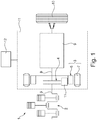
- Fig. 1 is a schematic diagram of a drive train of a hybrid vehicle shown.
- This drive train 1 comprises an internal combustion engine 2 and an electric motor 3. Between the internal combustion engine 2 and the electric motor 3, a hybrid separating clutch 4 is arranged directly behind the internal combustion engine 2. Internal combustion engine 2 and hybrid disconnect clutch 4 are connected to each other via a crankshaft 5.
- the electric motor 3 has a rotatable rotor 6 and a fixed stator 7.
- the output shaft 8 of the hybrid disconnect clutch 4 is connected to a transmission 9, which contains a coupling element (not further shown), for example a second clutch or a torque converter, which is arranged between the electric motor 3 and the transmission 9.
- the transmission 9 transmits the torque generated by the internal combustion engine 2 and / or the electric motor 3 to the drive wheels 10 of the hybrid vehicle.
- the hybrid separation clutch 4 and the transmission 9 thereby form a transmission system 11, which is controlled by a hydrostatic actuator 12.
- the hybrid disconnect clutch 4 is an unactuated closed clutch (normally closed).
- the method is also applicable without major changes in a "normally open” coupling.
- the arranged between the engine 2 and the electric motor 3 hybrid disconnect clutch 4 is closed to with while driving the hybrid vehicle with the torque generated by the electric motor 3 to start the engine 2 or to drive during a boost operation with driving internal combustion engine 2 and electric motor 3.
- the hybrid separation clutch 4 is actuated by the electrostatic clutch actuator 12.
- Hybrid disconnect clutch 4 In order to ensure that when the engine 2 is restarted by the electric motor 3, sufficient torque is provided from the electric torque 3, which both moves the hybrid vehicle via the drive wheels 10 without loss of comfort and at the same time actually starts the engine 2, a precise knowledge of a clutch characteristic is Hybrid disconnect clutch 4 is required, in which a clutch torque is shown above the Aktorweg. An interface of this clutch characteristic is the touch point, by which the position of the hybrid disconnect clutch is to be understood, in which the friction surfaces of the input or output part of the hybrid disconnect clutch in frictional contact with each other.
- This touch point is of particular importance for the control of the hybrid disconnect clutch and is thus determined during the initial startup of the hybrid vehicle and adapted during the driving operation of the hybrid vehicle.
- the determination of the touch point takes place when the internal combustion engine is shut down.
- a clutch desired torque applied to the hybrid disconnect clutch 4 is progressively increased until a drive torque which can be assigned to the desired clutch torque can be detected at the electric motor 3.
- the prerequisite is that the hybrid disconnect clutch 4 is in an open state and is then fed slowly under observation of the torque of the electric motor 3, wherein the electric motor 3 comprehensive electric traction drive is in a variable speed operation, ie at a stable speed.
- the hybrid disconnect clutch 4 is thus closed until the friction engagement surfaces of input and output part of the hybrid disconnect clutch 4 are in frictional contact and a minimum torque is transmitted to the electric motor 4, which is detected by a corresponding reaction of the electric motor 3.
- This corresponding reaction consists in that a defined torque increase is given by the electric motor 3.
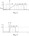
- the commissioning routine consists of eight phases, with in Fig. 2 the Aktorweg s over a time t is shown. The dashed line represents the expected contact point tp.
- the hybrid disconnect clutch 4 is opened, and it is a torque offset of the electric motor 3 of the electric traction drive determined. By closing the hybrid disconnect clutch 4, the torque of the electric motor 3 is increased by the thus determined offset.
- phase II the hybrid disconnect clutch 4 is closed to a minimum touch point position tp min , wherein this minimum touch point position was tp min calculated. Upon adjustment of this minimum touch point position, which takes a predetermined time, the torque of the electric traction drive 3 is further observed.
- phase III the hybrid disconnect clutch 4 is slowly closed, the hybrid disconnect clutch 4 has a constant speed. During the closing of the hybrid disconnect clutch 4, the torque of the electric motor 3 of the electric traction drive is further observed. Subsequently, a phase IV is reached, in which the torque of the electric motor 3 of the electric traction drive exceeds a predetermined threshold.
- This predefined threshold value is gradually increased by cyclically passing through the phase III and IV to a maximum of one Tast Vietnamesemoment until the electric motor 3 of the electric traction drive indicates a torque increase of a minimum of the height of the Tast Vietnamesemomentes.
- different torque levels for example, 1 Newton, 3 Newton or 5 Newton are used as a predefined threshold.
- the hybrid disconnect clutch 4 is gradually brought to the Tast Vietnamesemoment. This stepwise introduction is repeated in phases V and VI, where phase V is phase III and phase VI is phase IV.
- the touch point tp is adapted via a control-technical observer to ensure that the hybrid disconnect clutch 4 is closed in order not to reach an undefined state in the clutch torque hysteresis. By only closing the hybrid disconnect clutch 4, it is ensured that the hybrid disconnect clutch moves only on a hysteresis branch.
- the hybrid disconnect clutch 4 is opened again and checked whether the torque level of the electric motor 3 of the electric traction drive at the end of the commissioning process again corresponds to the torque level, which has output the electric motor of the electric traction drive at the beginning of the commissioning routine.
- the commissioning routine is used, which in connection with Fig. 2 was used for the first commissioning of the hybrid vehicle. Since a first touch point tp is already known by the first commissioning, this is, as in Fig. 3 shown used in phase II to move the hybrid disconnect clutch 4 to just before a known Tast Vietnameseposition. The fast start of the hybrid disconnect clutch 4 to the known Tast Vietnameseposition thus shortening the phases I and II. It also follows the phase III, in which the hybrid disconnect clutch 4 is slowly closed and observed by the electric motor 3 of the electric traction drive torque further observed becomes. Since you can approach relatively close due to the knowledge of a previous touch point on the current touch point tp, the phase III is also shortened.
- phase VII the touch point tp is adapted here via a control technical observer
- phase VIII the hybrid disconnect clutch 4 is opened and the torque level of the electric motor 3 of the electric traction drive with the hybrid disconnect clutch 4 open at the end of the adaptation phase with the torque level of the electric motor 3 of the electric traction drive is compared with the hybrid disconnect clutch 4 open in phase I.
- Fig. 3 the adaptation of the current touch point tp during the drive of the hybrid vehicle compared to the initial commissioning is significantly shortened.
- the touch point is determined during the driving operation of the hybrid vehicle as well as during commissioning. Since the touch point is precisely predetermined by the first commissioning, you can close the hybrid disconnect clutch 4 until just before the expected current sensing point and then continue to close until the defined engine torque change is detected.
Description
- Die Erfindung betrifft ein Verfahren zur Ermittlung eines Tastpunktes einer Hybridtrennkupplung eines Hybridfahrzeuges, welche von einem hydrostatischen Kupplungsaktor betätigt wird, wobei die Hybridtrennkupplung einen Verbrennungsmotor und einen Elektrotraktionsantrieb trennt oder verbindet und der Tastpunkt bei stillstehendem Verbrennungsmotor durch langsames Betätigen der Hybridtrennkupplung, ausgehend von einer Position der Hybridtrennkupplung, welche diese in einem unbetätigten Zustand einnimmt, unter Beobachtung eines Momentes des Elektrotraktionsantriebes bestimmt wird, wenn eine definierte Momentenerhöhung detektiert wird, sowie eine Vorrichtung zur Durchführung des Verfahrens.
- Die
DE 10 2010 024 941 A1 offenbart ein Verfahren zur Steuerung eines Doppelkupplungsgetriebes mit mindestens zwei Teilantriebssträngen, von denen jeder mittels einer Kupplung mit einer Brennkraftmaschine koppelbar ist. Im Fahrbetrieb des, das Doppelkupplungsgetriebe umfassenden Fahrzeuges wird ein Tastpunkt der Kupplung unabhängig vom Motormoment ermittelt. Dieser Tastpunkt wird dabei während der Inbetriebnahme des Fahrzeuges bestimmt und dann während des Betriebes des Fahrzeuges adaptiert. - Bei einem Hybridfahrzeug mit hybridischem Antriebsstrang kann der Fahrwiderstand aus zwei unabhängigen Energiequellen, wie Kraftstoff eines Verbrennungsmotors und elektrische Energie aus einer Traktionsbatterie eines Elektromotors, durch Umwandlung in mechanische Energie überwunden werden. Gemäß der
DE 10 2008 030 473 A1 ist ein Verfahren zur Tastpunktermittlung einer automatisierten Hybridtrennkupplung in einem Hybridantriebsstrang bekannt. Der Tastpunkt der Hybridtrennkupplung, welche zwischen einem Verbrennungsmotor und einem Elektrotraktionsantrieb angeordnet ist, wird bei stillgesetztem Verbrennungsmotor bestimmt, indem die Hybridtrennkupplung langsam geschlossen wird und der Einfluss der sich schließenden Hybridtrennkupplung auf eine Elektromaschine des Elektrotraktionsantriebes, die mit einer vorgegebenen Drehzahl rotiert, ausgewertet wird. Diese Hybridtrennkupplung ermöglicht im geöffneten Zustand ein rein elektrisches Fahren des Hybridfahrzeuges, während im geschlossenen Zustand das Drehmoment des Verbrennungsmotors zum Antriebsrad geführt wird. - Eine weitere Aufgabe der Hybridtrennkupplung besteht in dem Start des Verbrennungsmotors. Hierzu wird durch gezielte Erhöhung des Drehmomentes des Elektromotors und Schließen der Hybridtrennkupplung Energie zum stehenden Verbrennungsmotor übertragen und dieser somit beschleunigt. Hinsichtlich des Fahrkomforts muss dabei das von der Hybridtrennkupplung übertragene Drehmoment exakt bekannt sein, um ungewollte Fahrzeugbeschleunigungen zu vermeiden, da das Drehmoment des Elektromotors gleichzeitig auch auf die Antriebsräder übertragen wird.
- Das von der Hybridtrennkupplung übertragene Drehmoment ist direkt von der Position eines, die Hybridtrennkupplung betätigenden elektrostatischen Kupplungsaktors abhängig. Zur Abschätzung des übertragenen Kupplungsmomentes muss einerseits die Lage des Kupplungsaktors relativ zum möglichen Verfahrweg bekannt sein, andererseits muss eine Kupplungskennlinie (Kupplungsmoment in Abhängigkeit der Aktorposition) auf den Aktorweg referenziert werden. Der Tastpunkt stellt dabei eine Stützstelle der Kupplungskennlinie dar. Der Tastpunkt muss für den Betrieb einmalig ermittelt werden und während des Betriebes an das veränderte Kupplungsverhalten, welches aufgrund von verschiedenen Einschlussfaktoren wie Verschleiß, Nachstellung der Kupplung und Temperatur sowie Alterungsprozesse nicht konstant ist, angepasst werden. Es ist bekannt, den Tastpunkt bei der Inbetriebnahme des Hybridfahrzeuges durch einen Diagnoseservice zu ermitteln. Ein wesentlicher Nachteil dieser Ermittlung des Tastpunktes ist, dass die Tastpunktadaption, die während der Inbetriebnahme durchgeführt wird, für eine Adaption des Tastpunktes im Fahrbetrieb des Hybridfahrzeuges zu lange dauert.
- Aus der
US 2010/004837 A1 ist ein Verfahren zur Ermittlung eines Tastpunktes einer Hybridtrennkupplung eines Hybridfahrzeuges bekannt, welche von einem hydrostatischen Kupplungsaktor betätigt wird, wobei die Hybridtrennkupplung einen Verbrennungsmotor und einen Elektrotraktionsantrieb trennt oder verbindet und der Tastpunkt durch langsames Betätigen der Kupplung, ausgehend von einer Position der Hybridtrennkupplung, welche diese in einem unbetätigten Zustand einnimmt, unter Beobachtung eine Drehzahl des Elektrotraktionsantriebes bestimmt wird, wobei ein aktueller Tastpunkt während eines Betriebes des Hybridfahrzeuges adaptiert wird, wobei zur Adaption des aktuellen Tastpunktes während des Betriebes eine Inbetriebnahmeroutine genutzt wird, mit welcher ein erster Tastpunkt bei einer Inbetriebnahme des Hybridfahrzeuges ermittelt wird, und zur Ermittlung eines adaptierten Tastpunkts die Hybridtrennkupplung verschoben wird, bis die offene Position der Hybridtrennkupplung detektiert wird. - Bezüglich weiteren Standes der Technik wird auf die
US 6 022 295 A , dieEP 0 635 391 A2 , dieDE 100 31 438 A1 und dieWO 98/46445 A1 - Der Erfindung liegt somit die Aufgabe zugrunde, ein Verfahren zur Ermittlung eines Tastpunktes anzugeben, welches für die Adaption des Tastpunktes während der Fahrt des Hybridfahrzeuges genutzt werden kann.
- Erfindungsgemäß wird die Aufgabe dadurch gelöst, dass ein aktueller Tastpunkt während eines Betriebes des Hybridfahrzeuges adaptiert wird, wobei zur Adaption des aktuellen Tastpunktes während des Betriebes eine Inbetriebnahmeroutine genutzt wird, mit welcher ein erster Tastpunkt bei einer Inbetriebnahme des Hybridfahrzeuges ermittelt wird, wobei die Hybridtrennkupplung nahe an einem vorhergehend bestimmten Tastpunkt herangefahren wird und die Hybridtrennkupplung, ausgehend von diesem zuletzt bestimmten Tastpunkt, weiter verschoben wird, bis die definierte Momentenerhöhung detektiert wird. Dies hat den Vorteil, dass bei der Adaption des Tastpunktes während des Fahrbetriebes des Hybridfahrzeuges der Adaptionsvorgang wesentlich verkürzt werden kann, da ein vorhergehend bestimmter Tastpunkt der Tastpunktadaption zugrunde gelegt wird, wodurch sich die verwendete Inbetriebnahmeroutine wesentlich verkürzt. Der aktuelle Tastpunkt kann somit wesentlich schneller bestimmt werden.
- Vorteilhafterweise wird während der Inbetriebnahme des Hybridfahrzeuges mit der Inbetriebnahmeroutine der erste Tastpunkt der Hybridtrennkupplung ermittelt, welcher bei einer ersten Adaption zur Bestimmung des aktuellen Tastpunktes als vorhergehend bestimmter Tastpunkt zugrunde gelegt wird. Durch diesen während der Inbetriebnahme des Hybridfahrzeuges ermittelten ersten Tastpunkt ist der Bereich, in welchem eine Tastpunktverschiebung vermutet wird, bereits bekannt, so dass die Hybridtrennkupplung in der Adaptionsphase in diesem Bereich verfahren werden kann und somit die Zeitdauer zur Bestimmung des aktuellen Tastpunktes verkürzt wird.
- In einer Ausgestaltung wird als vorhergehend bestimmter Tastpunkt, der zuletzt bestimmte Tastpunkt zugrunde gelegt, welcher in der, der aktuellen Adaptionsphase unmittelbar vorhergehenden Adaptionsphase bestimmt wird. Auch bei dieser Vorgehensweise wird durch die Verwendung des beim unmittelbar vorhergehenden Adaptionszyklus ermittelten Tastpunkts ein sehr schnelles Heranfahren an einen möglichen aktuellen Tastpunkt ermöglicht, wodurch die Zeit zur Ermittlung des aktuellen Tastpunktes verkürzt wird.
- In einer Variante wird auf eine bevorstehend definierte Momentenerhöhung geschlossen, wenn ein vorgegebener Schwellwert der Momentenerhöhung überschritten wird, wobei der vorgegebene Schwellwert wiederholt solange auf ein maximal ansteigendes Tastpunktmoment angehoben wird, bis die von dem Elektrotraktionsantrieb ausgegebene Momentenerhöhung minimal der Höhe des Tastpunktmomentes entspricht. Durch das mehrfache Anfahren des Schwellwertes, welches vorzugsweise mit unterschiedlichen ansteigenden Momentenniveaus erfolgen kann, lässt sich eine besonders genaue Bestimmung des Tastpunktmomentes realisieren, weshalb der adaptierte aktuelle Tastpunkt genau ermittelt werden kann.
- In einer Ausführungsform wird der Tastpunkt der Hybridtrennkupplung aus dem Tastpunktmoment, welches der, von dem Elektrotraktionsantrieb ausgegebenen Momentenerhöhung entspricht, durch einen regeltechnischen Beobachter adaptiert. Dies ist notwendig, um nicht in der Kupplungsmomentenhysterese einen undefinierten Zustand zu erreichen.
- In einer Alternative wird der Tastpunkt der Hybridtrennkupplung aus dem Tastpunktmoment, welches der von dem Elektrotraktionsantrieb ausgegebenen Momentenerhöhung entspricht, aus einer Kennlinie der Hybridtrennkupplung adaptiert. Die Verwendung eines softwaremäßig und somit rechnerzeitaufwändigen regeltechnischen Beobachters kann somit entfallen.
- In einer Ausgestaltung wird nach erfolgter Adaption des Tastpunktes die Hybridtrennkupplung in die Position zurückgeführt, welche diese in unbestätigtem Zustand einnimmt, wobei geprüft wird, ob das von dem Elektrotraktionsantrieb abgegebene Moment mit dem Moment des Elektrotraktionsantriebes übereinstimmt, welches dieser bei dieser Position der Hybridtrennkupplung zu Beginn der aktuellen Adaptionsphase abgegeben hat. Damit wird untersucht, ob vor und nach der Adaptionsphase das Moment des Elektrotraktionsantriebes dasselbe Niveau aufweist, wodurch störende Einflüsse bei der Ermittlung des Tastpunktes ausgeschlossen werden können und somit der so ermittelte aktuelle Tastpunkt der Steuerung der Hybridtrennkupplung zugrunde gelegt werden kann.
- In einer Ausführungsform wird bei der Inbetriebnahme des Hybridfahrzeuges als vorhergehend bestimmter Tastpunkt ein berechneter Tastpunkt verwendet. Die Nutzung eines solchen berechneten Tastpunktes ermöglicht auch bei der erstmaligen Bestimmung des Tastpunktes, dass die Inbetriebnahmeroutine zur Bestimmung des Tastpunktes nicht zu lang ist, um sich dem tatsächlichen ersten Tastpunkt anzunähern.
- Eine Weiterbildung der Erfindung betrifft eine Vorrichtung zur Steuerung einer Hybridtrennkupplung eines Hybridfahrzeuges, welche von einem hydrostatischen Kupplungsaktor betätigbar ist, wobei die Hybridtrennkupplung zwischen einem Verbrennungsmotor und einem Elektrotraktionsantrieb angeordnet ist. Bei einer solchen Vorrichtung wird die Hybridtrennkupplung nach einem in dieser Schutzrechtsanmeldung ausgeführten Merkmal angesteuert.
- Die Erfindung lässt zahlreiche Ausführungsformen zu. Eine davon soll anhand der in der Zeichnung dargestellten Figuren näher erläutert werden.
- Es zeigen:
- Fig. 1
- eine Prinzipdarstellung eines Hybridantriebes,
- Fig. 2
- eine Prinzipdarstellung für eine Tastpunktbestimmung bei einer ersten Inbetriebnahme eines Hybridfahrzeuges nach dem erfindungsgemäßen Verfahren,
- Fig. 3
- eine Prinzipdarstellung einer Tastpunktbestimmung während des Betriebes des Hybridfahrzeuges nach dem erfindungsgemäßen Verfahren.
- Gleiche Merkmale sind mit gleichen Bezugszeichen gekennzeichnet.
- In
Fig. 1 ist eine Prinzipdarstellung eines Antriebsstranges eines Hybridfahrzeuges dargestellt. Dieser Antriebsstrang 1 umfasst einen Verbrennungsmotor 2 und einen Elektromotor 3. Zwischen dem Verbrennungsmotor 2 und dem Elektromotor 3 ist direkt hinter dem Verbrennungsmotor 2 eine Hybridtrennkupplung 4 angeordnet. Verbrennungsmotor 2 und Hybridtrennkupplung 4 sind über eine Kurbelwelle 5 miteinander verbunden. Der Elektromotor 3 weist einen drehbaren Rotor 6 und einen feststehenden Stator 7 auf. Die Abtriebswelle 8 der Hybridtrennkupplung 4 ist mit einem Getriebe 9 verbunden, welches ein nicht weiter dargestelltes Koppelelement, beispielsweise eine zweite Kupplung oder einen Drehmomentwandler enthält, die zwischen dem Elektromotor 3 und dem Getriebe 9 angeordnet ist. Das Getriebe 9 überträgt das von dem Verbrennungsmotor 2 und/oder dem Elektromotor 3 erzeugte Drehmoment auf die Antriebsräder 10 des Hybridfahrzeuges. Die Hybridtrennkupplung 4 und das Getriebe 9 bilden dabei ein Getriebesystem 11, welches von einem hydrostatischen Aktor 12 angesteuert wird. - Im Weiteren wird davon ausgegangen, dass es sich bei der Hybridtrennkupplung 4 um eine unbetätigt geschlossene Kupplung (normally closed) handelt. Das Verfahren ist aber auch ohne große Änderungen bei einer "normally open" Kupplung anwendbar. Die zwischen dem Verbrennungsmotor 2 und dem Elektromotor 3 angeordnete Hybridtrennkupplung 4 wird geschlossen, um während der Fahrt des Hybridfahrzeuges mit dem von dem Elektromotor 3 erzeugten Drehmoment den Verbrennungsmotor 2 zu starten oder während eines Boostbetriebes mit antreibendem Verbrennungsmotor 2 und Elektromotor 3 zu fahren. Die Hybridtrennkupplung 4 wird dabei von dem elektrostatischen Kupplungsaktor 12 betätigt. Um sicherzustellen, dass bei dem Wiederstart des Verbrennungsmotors 2 durch den Elektromotor 3 ein ausreichendes Drehmoment vom Elektromoment 3 bereitgestellt wird, welches sowohl das Hybridfahrzeug über die Antriebsräder 10 ohne Komfortverlust bewegt und gleichzeitig den Verbrennungsmotor 2 auch tatsächlich startet, ist eine genaue Kenntnis einer Kupplungskennlinie der Hybridtrennkupplung 4 erforderlich, bei welcher ein Kupplungsmoment über dem Aktorweg abgebildet ist. Eine Schnittstelle dieser Kupplungskennlinie ist der Tastpunkt, unter dem die Position der Hybridtrennkupplung zu verstehen ist, bei dem die Reibflächen des Ein- bzw. Ausgangsteils der Hybridtrennkupplung in Reibkontakt zueinander treten.
- Dieser Tastpunkt ist von besonderer Bedeutung für die Steuerung der Hybridtrennkupplung und wird somit während der Erstinbetriebnahme des Hybridfahrzeuges bestimmt und während des Fahrbetriebes des Hybridfahrzeuges adaptiert. Die Bestimmung des Tastpunktes erfolgt bei stillgelegtem Verbrennungsmotor. Zur Ermittlung des Tastpunktes wird ein an die Hybridtrennkupplung 4 angelegtes Kupplungssollmoment zunehmend vergrößert, bis an dem Elektromotor 3 ein dem Kupplungssollmoment zuordenbare Antriebsmoment erfassbar ist. Voraussetzung ist dabei, dass die Hybridtrennkupplung 4 in einem geöffneten Zustand sich befindet und anschließend langsam unter Beobachtung des Momentes des Elektromotors 3 zugefahren wird, wobei der den Elektromotor 3 umfassende Elektrotraktionsantriebs sich in einem drehzahlgeregelten Betrieb, also bei einer stabilen Drehzahl befindet. Die Hybridtrennkupplung 4 wird also zugefahren, bis die Reibeingriffsflächen von Ein- und Ausgangsteil der Hybridtrennkupplung 4 in Reibkontakt stehen und ein minimales Moment auf den Elektromotor 4 übertragen wird, das durch eine entsprechende Reaktion des Elektromotors 3 erfasst wird. Diese entsprechende Reaktion besteht darin, dass eine definierte Momentenerhöhung durch den Elektromotor 3 gegeben ist.
- Bei der erstmaligen Inbetriebnahme des Hybridfahrzeuges wird eine Inbetriebnahme zur Feststellung des ersten Tastpunktes initiiert, welche anhand von
Fig. 2 näher erläutert werden soll. Die Inbetriebnahmeroutine besteht dabei aus acht Phasen, wobei inFig. 2 der Aktorweg s über einer Zeit t dargestellt ist. Die gestrichelte Linie stellt dabei den zu erwartenden Tastpunkt tp dar. In der Phase I ist die Hybridtrennkupplung 4 geöffnet, und es wird ein Momenten-Offset des Elektromotors 3 des Elektrotraktionsantriebes bestimmt. Durch das Schließen der Hybridtrennkupplung 4 wird das Moment des Elektromotors 3 um das so bestimmte Offset erhöht. - In der Phase II wird die Hybridtrennkupplung 4 auf eine minimale Tastpunktposition tpmin geschlossen, wobei diese minimale Tastpunktposition tpmin rechnerisch festgelegt wurde. Bei Einstellung dieser minimalen Tastpunktposition, welche eine vorgegebene Zeit in Anspruch nimmt, wird das Moment des Elektrotraktionsantriebes 3 weiter beobachtet. In der anschließenden Phase III wird die Hybridtrennkupplung 4 langsam geschlossen, wobei die Hybridtrennkupplung 4 eine konstante Geschwindigkeit aufweist. Während des Schließens der Hybridtrennkupplung 4 wird weiter das Moment des Elektromotors 3 des Elektrotraktionsantriebes beobachtet. Anschließend wird eine Phase IV erreicht, in welcher das Moment des Elektromotors 3 des Elektrotraktionsantriebes einen vorgegebenen Schwellwert überschreitet. Dieser vordefinierte Schwellwert wird stufenförmig durch zyklisches Durchlaufen der Phase III und IV auf maximal ein Tastpunktmoment angehoben, bis der Elektromotor 3 des Elektrotraktionsantriebes eine Momentenerhöhung von minimal der Höhe des Tastpunktmomentes anzeigt. Bei dem zyklischen Durchlaufen der Phasen III und IV werden unterschiedliche Momentenniveaus von beispielsweise 1 Newton, 3 Newton oder 5 Newton als vordefinierter Schwellwert eingesetzt. Somit wird die Hybridtrennkupplung 4 allmählich an das Tastpunktmoment herangeführt. Dieses stufenweise Heranführen wird in den Phasen V und VI wiederholt, wobei die Phase V der Phase III und die Phase VI der Phase IV entspricht.
- In der sich daran anschließenden Phase VII wird der Tastpunkt tp über einen regelungstechnischen Beobachter adaptiert, um sicherzustellen, dass die Hybridtrennkupplung 4 geschlossen ist, um nicht in der Kupplungsmomentenhysterese einen undefinierten Zustand zu erreichen. Durch das nur Schließen der Hybridtrennkupplung 4 wird gewährleistet, dass die Hybridtrennkupplung sich nur auf einem Hystereseast bewegt.
- Abschließend wird in einer Phase VIII die Hybridtrennkupplung 4 wieder geöffnet und geprüft, ob das Momentenniveau des Elektromotors 3 des Elektrotraktionsantriebes zum Abschluss des Inbetriebnahmevorgangs wieder dem Momentenniveau entspricht, welches der Elektromotors des Elektrotraktionsantriebes bei Beginn der Inbetriebnahmeroutine ausgegeben hat.
- An diese Inbetriebnahmeroutine, in welcher der Tastpunkt tp erstmalig ermittelt wird, schließen sich während der Fahrt des Hybridfahrzeuges Adaptionsphasen an, in welchen der so bestimmte Tastpunkt tp adaptiert wird, um somit einer Veränderung des Tastpunktes tp durch Verschleiß, Temperatur und ähnlichem Rechnung zu tragen und eine genauere Ansteuerung des Kupplungsaktors 12 zu ermöglichen.
- Bei der Tastpunktadaption während der Fahrt des Hybridfahrzeuges wird die Inbetriebnahmeroutine benutzt, welche im Zusammenhang mit
Fig. 2 bei der erstmaligen Inbetriebnahme des Hybridfahrzeuges verwendet wurde. Da durch die Erstinbetriebnahme bereits ein erster Tastpunkt tp bekannt ist, wird dieser, wie inFig. 3 dargestellt, in der Phase II verwendet, um die Hybridtrennkupplung 4 bis kurz vor eine schon bekannte Tastpunktposition zu bewegen. Durch das schnelle Anfahren der Hybridtrennkupplung 4 an die bekannte Tastpunktposition verkürzen sich somit die Phasen I und II. Es schließt sich auch hier die Phase III an, in welcher die Hybridtrennkupplung 4 langsam geschlossen wird und das von dem Elektromotor 3 des Elektrotraktionsantriebes ausgegebene Moment weiter beobachtet wird. Da man aufgrund des Bekanntseins eines vorhergehenden Tastpunktes an den aktuellen Tastpunkt tp schon relativ nahe heranfahren kann, verkürzt sich die Phase III ebenfalls. Eine zyklische Wiederholung zur Erkennung des Tastpunktes entfällt, weshalb von Phase III sofort auf die Phase VI und Phase VII übergegangen wird. In der Phase VII wird auch hier der Tastpunkt tp über einen regelungstechnischen Beobachter adaptiert, während in der Phase VIII die Hybridtrennkupplung 4 geöffnet wird und das Momentenniveau des Elektromotors 3 des Elektrotraktionsantriebes bei geöffneter Hybridtrennkupplung 4 zum Schluss der Adaptionsphase mit dem Momentenniveau des Elektromotors 3 des Elektrotraktionsantriebes bei geöffneter Hybridtrennkupplung 4 in der Phase I verglichen wird. Wie ausFig. 3 ersichtlich, verkürzt sich die Adaption des aktuellen Tastpunktes tp während der Fahrt des Hybridfahrzeuges gegenüber der Erstinbetriebnahme wesentlich. - Statt den Tastpunkt komplett durch den Beobachter neu zu berechnen, ist es vorteilhaft, den alten Tastpunkt in Richtung des aktuellen Tastpunktes zu verändern. Dies hat eine glättende Wirkung, wodurch falsch bestimmte Tastpunkte nur einen reduzierten Einfluss haben. Die Phase VII kann vollständig entfallen, wenn anstelle des regelungstechnischen Beobachters der Tastpunkt über die Kupplungskennlinie berechnet wird. Bei der Verwendung des Elektromotors 3 des Elektrotraktionsantriebes ist die Adaption des Tastpunktes bei positiven als auch bei negativen Drehzahlen möglich. Alternativ kann man die verkürzte Tastpunktroutine auch beim Tasten gegen den Verbrennungsmotor einsetzen.
- Bei der vorgeschlagenen Bestimmung des Tastpunktes wird der Tastpunkt während des Fahrbetriebes des Hybridfahrzeuges genauso ermittelt wie bei der Inbetriebnahme. Da der Tastpunkt durch die Erstinbetriebnahme genau vorbestimmt ist, kann man die Hybridtrennkupplung 4 schon bis kurz vor dem zu erwartenden aktuellen Tastpunkt schließen und dann weiter schließen, bis die definierte Motormomentänderung detektiert wird.
-
- 1
- Antriebsstrang
- 2
- Verbrennungsmotor
- 3
- Elektromotor
- 4
- Hybridtrennkupplung
- 5
- Kurbelwelle
- 6
- Rotor
- 7
- Stator
- 8
- Abtriebswelle
- 9
- Getriebe
- 10
- Antriebsräder
- 11
- Getriebesystem
- 12
- Hydrostatischer Aktor
Claims (9)
- Verfahren zur Ermittlung eines Tastpunktes einer Hybridtrennkupplung eines Hybridfahrzeuges, welche von einem hydrostatischen Kupplungsaktor (12) betätigt wird, wobei die Hybridtrennkupplung (4) einen Verbrennungsmotor (2) und einen Elektrotraktionsantrieb (3) trennt oder verbindet und der Tastpunkt durch langsames Betätigen der Kupplung, ausgehend von einer Position der Hybridtrennkupplung (4), welche diese in einem unbetätigten Zustand einnimmt, unter Beobachtung eines Momentes des Elektrotraktionsantriebes (3) bestimmt wird, wenn eine definierte Momentenerhöhung detektiert wird, dadurch gekennzeichnet, dass ein aktueller Tastpunkt (tp) während eines Betriebes des Hybridfahrzeuges adaptiert wird, wobei zur Adaption des aktuellen Tastpunktes (tp) während des Betriebes eine Inbetriebnahmeroutine genutzt wird, mit welcher ein erster Tastpunkt bei einer Inbetriebnahme des Hybridfahrzeuges ermittelt wird, wobei die Hybridtrennkupplung (4) nahe an einen vorhergehend bestimmten Tastpunkt herangefahren wird und die Hybridtrennkupplung (4), ausgehend von diesem vorhergehend bestimmten Tastpunkt, weiter verschoben wird, bis die definierte Momentenerhöhung detektiert wird.
- Verfahren nach Anspruch 1, dadurch gekennzeichnet, dass während der Inbetriebnahme des Hybridfahrzeuges mit der Inbetriebnahmeroutine der erste Tastpunkt der Hybridtrennkupplung (4) ermittelt wird, welcher bei einer ersten Adaption zur Bestimmung des aktuellen Tastpunktes (tp) während des Betriebes des Hybridfahrzeuges als vorhergehend bestimmter Tastpunkt zugrunde gelegt wird.
- Verfahren nach Anspruch 1 oder 2, dadurch gekennzeichnet, dass als vorhergehend bestimmter Tastpunkt, der zuletzt bestimmte Tastpunkt verwendet wird, welcher in der, der aktuellen Adaptionsphase unmittelbar vorausgehenden Adaptionsphase bestimmt wurde.
- Verfahren nach Anspruch 1, 2 oder 3, dadurch gekennzeichnet, dass auf eine bevorstehend definierte Momentenerhöhung geschlossen wird, wenn ein vorgegebener Schwellwert der Momentenerhöhung überschritten wird, wobei der vorgegebene Schwellwert solange wiederholt auf maximal ein ansteigendes Tastpunktmoment angehoben wird, bis die von dem Elektrotraktionsantrieb (3) ausgegebene Momentenerhöhung minimal der Höhe des Tastpunktmomentes entspricht.
- Verfahren nach Anspruch 4, dadurch gekennzeichnet, dass der Tastpunkt der Hybridtrennkupplung (4) aus dem Tastpunktmoment, welches der von dem Elektrotraktionsantrieb (3) ausgegebenen Momentenerhöhung entspricht, durch einen regeltechnischen Beobachter adaptiert wird.
- Verfahren nach Anspruch 4, dadurch gekennzeichnet, dass der Tastpunkt der Hybridtrennkupplung (4) aus dem Tastpunktmoment, welches der von dem Elektrotraktionsantrieb (3) ausgegebenen Momentenerhöhung entspricht, aus einer Kennlinie der Hybridtrennkupplung (4) adaptiert wird.
- Verfahren nach mindestens einem der vorhergehenden Ansprüche, dadurch gekennzeichnet, dass nach erfolgter Adaption des Tastpunktes die Hybridtrennkupplung (4) in die Position zurückgeführt wird, welche diese im unbetätigten Zustand einnimmt, wobei geprüft wird, ob das von dem Elektrotraktionsantrieb (3) abgegebene Moment mit dem Moment des Elektrotraktionsantriebes (3) übereinstimmt, welches dieser bei dieser Position der Hybridtrennkupplung (4) zu Beginn der aktuellen Adaptionsphase abgegeben hat.
- Verfahren nach mindestens einem der vorhergehenden Ansprüche, dadurch gekennzeichnet, dass bei der Inbetriebnahme des Hybridfahrzeuges als vorhergehend bestimmter Tastpunkt ein berechneter Tastpunkt verwendet wird.
- Vorrichtung zur Steuerung einer Hybridtrennkupplung eines Hybridfahrzeuges, welche von einem hydrostatischen Kupplungsaktor (12) betätigbar ist, wobei die Hybridtrennkupplung (4) zwischen einem Verbrennungsmotor (2) und einem Elektrotraktionsantrieb (3) angeordnet ist, dadurch gekennzeichnet, dass die Hybridtrennkupplung (4) nach einem Verfahren gemäß mindestens einem der vorhergehenden Ansprüche 1 bis 8 steuerbar ist.
Applications Claiming Priority (2)
| Application Number | Priority Date | Filing Date | Title |
|---|---|---|---|
| DE102014211381.4A DE102014211381A1 (de) | 2014-06-13 | 2014-06-13 | Verfahren und Vorrichtung zur Ermittlung eines Tastpunktes einer Hybridtrennkupplung eines Hybridfahrzeuges |
| PCT/DE2015/200350 WO2015188825A2 (de) | 2014-06-13 | 2015-06-09 | Verfahren und vorrichtung zur ermittlung eines tastpunktes einer hybridtrennkupplung eines hybridfahrzeuges |
Publications (2)
| Publication Number | Publication Date |
|---|---|
| EP3155281A2 EP3155281A2 (de) | 2017-04-19 |
| EP3155281B1 true EP3155281B1 (de) | 2018-06-06 |
Family
ID=53610736
Family Applications (1)
| Application Number | Title | Priority Date | Filing Date |
|---|---|---|---|
| EP15738255.7A Active EP3155281B1 (de) | 2014-06-13 | 2015-06-09 | Verfahren und vorrichtung zur ermittlung eines tastpunktes einer hybridtrennkupplung eines hybridfahrzeuges |
Country Status (5)
| Country | Link |
|---|---|
| US (1) | US10337574B2 (de) |
| EP (1) | EP3155281B1 (de) |
| CN (1) | CN106415046B (de) |
| DE (2) | DE102014211381A1 (de) |
| WO (1) | WO2015188825A2 (de) |
Families Citing this family (7)
| Publication number | Priority date | Publication date | Assignee | Title |
|---|---|---|---|---|
| DE102015216166A1 (de) | 2015-08-25 | 2017-03-02 | Schaeffler Technologies AG & Co. KG | Verfahren zur Adaption eines Tastpunktes einer automatisierten Trennkupplung im Antriebsstrang eines Hybrid-Fahrzeugs |
| DE102017107900A1 (de) | 2017-04-12 | 2018-10-18 | Schaeffler Technologies AG & Co. KG | Verfahren zur Überwachung eines Verschleißes einer Reibungskupplung eines automatisierten Kupplungssystems eines Kraftfahrzeuges |
| DE112018002821A5 (de) * | 2017-06-01 | 2020-02-13 | Schaeffler Technologies AG & Co. KG | Verfahren zur Erkennung einer durchgeführten Selbstnachstellung einer automatisierten unbetätigt geschlossenen Kupplung eines Fahrzeuges, vorzugsweise einer Hybridtrennkupplung eines Hybridfahrzeuges |
| DE102018112551A1 (de) * | 2017-06-26 | 2018-12-27 | Schaeffler Technologies AG & Co. KG | Verfahren und Steuer- und Regeleinrichtung zur Kompensation eines Kupplungsmoments einer Hybridtrennkupplung unter Berücksichtigung der Drehzahl einer elektrischen Maschine |
| CN112243417A (zh) * | 2018-07-19 | 2021-01-19 | 舍弗勒技术股份两合公司 | 混合动力系统的换挡控制方法、换挡控制装置、换挡控制系统及混合动力系统 |
| US11891042B2 (en) * | 2020-02-19 | 2024-02-06 | Dana Automotive Systems Group, Llc | System and method for characterizing a clutch |
| CN112032294B (zh) * | 2020-09-14 | 2021-11-26 | 一汽解放汽车有限公司 | 一种车辆操作方法和装置 |
Family Cites Families (12)
| Publication number | Priority date | Publication date | Assignee | Title |
|---|---|---|---|---|
| US5393274A (en) * | 1993-07-19 | 1995-02-28 | Eaton Corporation | Touch point identification algorithm for automatic clutch controller |
| US6364813B1 (en) | 1997-04-16 | 2002-04-02 | Transmisiones Tsp, S.A. De C.V. | Method and apparatus for operating a clutch in an automated mechanical transmission |
| US6022295A (en) | 1998-11-12 | 2000-02-08 | Eaton Corporation | Touch point identification for vehicle master clutch |
| JP2001010360A (ja) | 1999-06-28 | 2001-01-16 | Suzuki Motor Corp | ハイブリッド動力車両 |
| US20100048374A1 (en) * | 2005-11-16 | 2010-02-25 | James Jenq Liu | System and Method for Fabricating Ceramic Substrates |
| EP2014946B1 (de) | 2007-07-12 | 2011-10-26 | Schaeffler Technologies AG & Co. KG | Verfahren zur Tastpunktermittlung einer automatisierten Kupplung |
| US8738256B2 (en) * | 2008-07-01 | 2014-05-27 | Eaton Corporation | Automatic calibration of the torque transfer touch point in an electrically actuated clutch in a hybrid vehicle |
| DE112010002949B4 (de) | 2009-07-16 | 2024-01-04 | Schaeffler Technologies AG & Co. KG | Verfahren und Vorrichtung zum Steuern eines Doppelkupplungsgetriebes |
| SE534245C2 (sv) * | 2009-09-14 | 2011-06-14 | Scania Cv Ab | Metod och system för bestämning av kontaktpunkten för en koppling vid ett fordon |
| SE535679C2 (sv) * | 2011-03-14 | 2012-11-06 | Scania Cv Ab | Förfarande och system vid bestämning av en kontaktpunkt för en koppling |
| JP5892891B2 (ja) * | 2012-08-02 | 2016-03-23 | アイシン精機株式会社 | ハイブリッド駆動装置 |
| DE112013007010B4 (de) * | 2013-04-30 | 2023-06-15 | Toyota Jidosha Kabushiki Kaisha | Steuervorrichtung für ein Fahrzeug |
-
2014
- 2014-06-13 DE DE102014211381.4A patent/DE102014211381A1/de not_active Withdrawn
-
2015
- 2015-06-09 EP EP15738255.7A patent/EP3155281B1/de active Active
- 2015-06-09 CN CN201580031265.0A patent/CN106415046B/zh active Active
- 2015-06-09 WO PCT/DE2015/200350 patent/WO2015188825A2/de active Application Filing
- 2015-06-09 US US15/307,927 patent/US10337574B2/en active Active
- 2015-06-09 DE DE112015002794.7T patent/DE112015002794A5/de not_active Withdrawn
Non-Patent Citations (1)
| Title |
|---|
| None * |
Also Published As
| Publication number | Publication date |
|---|---|
| US20170067518A1 (en) | 2017-03-09 |
| WO2015188825A9 (de) | 2016-03-24 |
| DE102014211381A1 (de) | 2015-12-17 |
| EP3155281A2 (de) | 2017-04-19 |
| US10337574B2 (en) | 2019-07-02 |
| CN106415046A (zh) | 2017-02-15 |
| WO2015188825A2 (de) | 2015-12-17 |
| CN106415046B (zh) | 2018-11-27 |
| WO2015188825A3 (de) | 2016-02-04 |
| DE112015002794A5 (de) | 2017-03-02 |
Similar Documents
| Publication | Publication Date | Title |
|---|---|---|
| EP3155281B1 (de) | Verfahren und vorrichtung zur ermittlung eines tastpunktes einer hybridtrennkupplung eines hybridfahrzeuges | |
| EP2665632B1 (de) | Verfahren und vorrichtung zum betreiben einer antriebsvorrichtung | |
| EP2443011B1 (de) | Verfahren und vorrichtung zur bestimmung des beginns einer startphase eines verbrennungsmotors in einem hybridfahrzeug | |
| EP3243009B1 (de) | Verfahren zur ermittlung eines tastpunktes einer hybridtrennkupplung eines hybridfahrzeuges | |
| WO2015192847A2 (de) | Verfahren zur ermittlung einer tastpunktänderung einer hybridtrennkupplung eines hybridfahrzeuges | |
| WO2016008463A1 (de) | Verfahren zur bestimmung einer tastpunktänderung und zur adaption eines reibwertes einer hybridtrennkupplung eines hybridfahrzeuges | |
| WO2010034570A1 (de) | Verfahren und vorrichtung zum betrieb einer hybridantriebsvorrichtung während des startens einer brennkraftmaschine | |
| DE102015208822A1 (de) | Verfahren zur Betätigung einer automatisierten Trennkupplung eines Hybridantriebsstranges eines Kraftfahrzeuges und Kupplungsbetätigungssystem | |
| WO2011076487A1 (de) | Verfahren und vorrichtung zum einkuppeln einer klauenkupplung zum antrieb einer achse eines kraftfahrzeuges | |
| DE102016201104A1 (de) | Verfahren zur prüfstandsfreien Bestimmung einer Kennlinie einer Hybridtrennkupplung eines Hybridfahrzeuges | |
| DE102016215855B4 (de) | Verfahren zur Bestimmung eines Tastpunktes einer Hybridtrennkupplung eines Hybridfahrzeuges | |
| DE102018128961A1 (de) | Verfahren zur Ermittlung einer Kupplungskenngröße im Generatorbetrieb | |
| DE102015221031B4 (de) | Verfahren zur Ermittlung eines Tastpunktes und eines Reibwertes einer Hybridtrennkupplung eines Hybridfahrzeuges | |
| DE102016200689B4 (de) | Verfahren zur Ermittlung eines Tastpunktes einer Hybridtrennkupplung eines Hybridfahrzeuges | |
| DE102018130679A1 (de) | Verfahren zur Bestimmung eines Tastpunktes einer Hybridtrennkupplung eines Hybridfahrzeuges | |
| DE102014009715B4 (de) | Verfahren zum Betreiben einer Antriebseinrichtung eines Kraftfahrzeugs sowie entsprechende Antriebseinrichtung | |
| DE102008044016A1 (de) | Verfahren zum Erfassen eines sich einstellenden Drehmomentes für einen Hybridantrieb | |
| DE102008051295A1 (de) | Verfahren zur Steuerung eines Hybridantriebsstranges und paralleler Hybridantriebsstrang | |
| WO2020114549A1 (de) | Verfahren zum start eines verbrennungsmotors eines hybridfahrzeuges | |
| WO2019038394A1 (de) | Impulsstart in einem hybrid-antriebsstrang | |
| DE102017203371A1 (de) | Verfahren zur Zustandsermittlung einer Kupplung im Kraftfahrzeug-Antriebsstrang, sowie zum Betrieb eines Hybridfahrzeug-Antriebsstrangs | |
| DE102017127107A1 (de) | Verfahren zur Bestimmung eines Kupplungsmomentes einer Kupplung eines motorgetriebenen Fahrzeuges | |
| DE102018117310A1 (de) | Verfahren zur Verbesserung der Genauigkeit bei einer Tastpunktermittlung einer automatisierten Kupplung in einem Kraftfahrzeug mit einem Verbrennungsmotor | |
| DE102014223102B4 (de) | Verfahren zur Korrektur von Modellparametern einer Kupplung, vorzugsweise für ein Kraftfahrzeug. | |
| DE102014208781A1 (de) | Verfahren und Steuerungseinrichtung zur Bestimmung eines Referenzpunkts für einen Anlegepunkt einer Kupplung |
Legal Events
| Date | Code | Title | Description |
|---|---|---|---|
| PUAI | Public reference made under article 153(3) epc to a published international application that has entered the european phase |
Free format text: ORIGINAL CODE: 0009012 |
|
| 17P | Request for examination filed |
Effective date: 20170113 |
|
| AK | Designated contracting states |
Kind code of ref document: A2 Designated state(s): AL AT BE BG CH CY CZ DE DK EE ES FI FR GB GR HR HU IE IS IT LI LT LU LV MC MK MT NL NO PL PT RO RS SE SI SK SM TR |
|
| AX | Request for extension of the european patent |
Extension state: BA ME |
|
| DAV | Request for validation of the european patent (deleted) | ||
| DAX | Request for extension of the european patent (deleted) | ||
| GRAP | Despatch of communication of intention to grant a patent |
Free format text: ORIGINAL CODE: EPIDOSNIGR1 |
|
| INTG | Intention to grant announced |
Effective date: 20180102 |
|
| GRAS | Grant fee paid |
Free format text: ORIGINAL CODE: EPIDOSNIGR3 |
|
| GRAA | (expected) grant |
Free format text: ORIGINAL CODE: 0009210 |
|
| AK | Designated contracting states |
Kind code of ref document: B1 Designated state(s): AL AT BE BG CH CY CZ DE DK EE ES FI FR GB GR HR HU IE IS IT LI LT LU LV MC MK MT NL NO PL PT RO RS SE SI SK SM TR |
|
| REG | Reference to a national code |
Ref country code: GB Ref legal event code: FG4D Free format text: NOT ENGLISH |
|
| REG | Reference to a national code |
Ref country code: CH Ref legal event code: EP Ref country code: AT Ref legal event code: REF Ref document number: 1006429 Country of ref document: AT Kind code of ref document: T Effective date: 20180615 |
|
| REG | Reference to a national code |
Ref country code: IE Ref legal event code: FG4D Free format text: LANGUAGE OF EP DOCUMENT: GERMAN |
|
| REG | Reference to a national code |
Ref country code: FR Ref legal event code: PLFP Year of fee payment: 4 |
|
| REG | Reference to a national code |
Ref country code: DE Ref legal event code: R096 Ref document number: 502015004575 Country of ref document: DE |
|
| REG | Reference to a national code |
Ref country code: NL Ref legal event code: MP Effective date: 20180606 |
|
| REG | Reference to a national code |
Ref country code: LT Ref legal event code: MG4D |
|
| PG25 | Lapsed in a contracting state [announced via postgrant information from national office to epo] |
Ref country code: LT Free format text: LAPSE BECAUSE OF FAILURE TO SUBMIT A TRANSLATION OF THE DESCRIPTION OR TO PAY THE FEE WITHIN THE PRESCRIBED TIME-LIMIT Effective date: 20180606 Ref country code: CY Free format text: LAPSE BECAUSE OF FAILURE TO SUBMIT A TRANSLATION OF THE DESCRIPTION OR TO PAY THE FEE WITHIN THE PRESCRIBED TIME-LIMIT Effective date: 20180606 Ref country code: SE Free format text: LAPSE BECAUSE OF FAILURE TO SUBMIT A TRANSLATION OF THE DESCRIPTION OR TO PAY THE FEE WITHIN THE PRESCRIBED TIME-LIMIT Effective date: 20180606 Ref country code: ES Free format text: LAPSE BECAUSE OF FAILURE TO SUBMIT A TRANSLATION OF THE DESCRIPTION OR TO PAY THE FEE WITHIN THE PRESCRIBED TIME-LIMIT Effective date: 20180606 Ref country code: NO Free format text: LAPSE BECAUSE OF FAILURE TO SUBMIT A TRANSLATION OF THE DESCRIPTION OR TO PAY THE FEE WITHIN THE PRESCRIBED TIME-LIMIT Effective date: 20180906 Ref country code: BG Free format text: LAPSE BECAUSE OF FAILURE TO SUBMIT A TRANSLATION OF THE DESCRIPTION OR TO PAY THE FEE WITHIN THE PRESCRIBED TIME-LIMIT Effective date: 20180906 Ref country code: FI Free format text: LAPSE BECAUSE OF FAILURE TO SUBMIT A TRANSLATION OF THE DESCRIPTION OR TO PAY THE FEE WITHIN THE PRESCRIBED TIME-LIMIT Effective date: 20180606 |
|
| PG25 | Lapsed in a contracting state [announced via postgrant information from national office to epo] |
Ref country code: RS Free format text: LAPSE BECAUSE OF FAILURE TO SUBMIT A TRANSLATION OF THE DESCRIPTION OR TO PAY THE FEE WITHIN THE PRESCRIBED TIME-LIMIT Effective date: 20180606 Ref country code: LV Free format text: LAPSE BECAUSE OF FAILURE TO SUBMIT A TRANSLATION OF THE DESCRIPTION OR TO PAY THE FEE WITHIN THE PRESCRIBED TIME-LIMIT Effective date: 20180606 Ref country code: GR Free format text: LAPSE BECAUSE OF FAILURE TO SUBMIT A TRANSLATION OF THE DESCRIPTION OR TO PAY THE FEE WITHIN THE PRESCRIBED TIME-LIMIT Effective date: 20180907 Ref country code: HR Free format text: LAPSE BECAUSE OF FAILURE TO SUBMIT A TRANSLATION OF THE DESCRIPTION OR TO PAY THE FEE WITHIN THE PRESCRIBED TIME-LIMIT Effective date: 20180606 |
|
| PG25 | Lapsed in a contracting state [announced via postgrant information from national office to epo] |
Ref country code: NL Free format text: LAPSE BECAUSE OF FAILURE TO SUBMIT A TRANSLATION OF THE DESCRIPTION OR TO PAY THE FEE WITHIN THE PRESCRIBED TIME-LIMIT Effective date: 20180606 |
|
| PG25 | Lapsed in a contracting state [announced via postgrant information from national office to epo] |
Ref country code: EE Free format text: LAPSE BECAUSE OF FAILURE TO SUBMIT A TRANSLATION OF THE DESCRIPTION OR TO PAY THE FEE WITHIN THE PRESCRIBED TIME-LIMIT Effective date: 20180606 Ref country code: IS Free format text: LAPSE BECAUSE OF FAILURE TO SUBMIT A TRANSLATION OF THE DESCRIPTION OR TO PAY THE FEE WITHIN THE PRESCRIBED TIME-LIMIT Effective date: 20181006 Ref country code: SK Free format text: LAPSE BECAUSE OF FAILURE TO SUBMIT A TRANSLATION OF THE DESCRIPTION OR TO PAY THE FEE WITHIN THE PRESCRIBED TIME-LIMIT Effective date: 20180606 Ref country code: RO Free format text: LAPSE BECAUSE OF FAILURE TO SUBMIT A TRANSLATION OF THE DESCRIPTION OR TO PAY THE FEE WITHIN THE PRESCRIBED TIME-LIMIT Effective date: 20180606 Ref country code: PL Free format text: LAPSE BECAUSE OF FAILURE TO SUBMIT A TRANSLATION OF THE DESCRIPTION OR TO PAY THE FEE WITHIN THE PRESCRIBED TIME-LIMIT Effective date: 20180606 Ref country code: CZ Free format text: LAPSE BECAUSE OF FAILURE TO SUBMIT A TRANSLATION OF THE DESCRIPTION OR TO PAY THE FEE WITHIN THE PRESCRIBED TIME-LIMIT Effective date: 20180606 |
|
| REG | Reference to a national code |
Ref country code: CH Ref legal event code: PL |
|
| PG25 | Lapsed in a contracting state [announced via postgrant information from national office to epo] |
Ref country code: IT Free format text: LAPSE BECAUSE OF FAILURE TO SUBMIT A TRANSLATION OF THE DESCRIPTION OR TO PAY THE FEE WITHIN THE PRESCRIBED TIME-LIMIT Effective date: 20180606 Ref country code: SM Free format text: LAPSE BECAUSE OF FAILURE TO SUBMIT A TRANSLATION OF THE DESCRIPTION OR TO PAY THE FEE WITHIN THE PRESCRIBED TIME-LIMIT Effective date: 20180606 |
|
| REG | Reference to a national code |
Ref country code: BE Ref legal event code: MM Effective date: 20180630 |
|
| REG | Reference to a national code |
Ref country code: DE Ref legal event code: R097 Ref document number: 502015004575 Country of ref document: DE |
|
| REG | Reference to a national code |
Ref country code: IE Ref legal event code: MM4A |
|
| PG25 | Lapsed in a contracting state [announced via postgrant information from national office to epo] |
Ref country code: LU Free format text: LAPSE BECAUSE OF NON-PAYMENT OF DUE FEES Effective date: 20180609 Ref country code: MC Free format text: LAPSE BECAUSE OF FAILURE TO SUBMIT A TRANSLATION OF THE DESCRIPTION OR TO PAY THE FEE WITHIN THE PRESCRIBED TIME-LIMIT Effective date: 20180606 |
|
| PLBE | No opposition filed within time limit |
Free format text: ORIGINAL CODE: 0009261 |
|
| STAA | Information on the status of an ep patent application or granted ep patent |
Free format text: STATUS: NO OPPOSITION FILED WITHIN TIME LIMIT |
|
| PG25 | Lapsed in a contracting state [announced via postgrant information from national office to epo] |
Ref country code: LI Free format text: LAPSE BECAUSE OF NON-PAYMENT OF DUE FEES Effective date: 20180630 Ref country code: CH Free format text: LAPSE BECAUSE OF NON-PAYMENT OF DUE FEES Effective date: 20180630 Ref country code: IE Free format text: LAPSE BECAUSE OF NON-PAYMENT OF DUE FEES Effective date: 20180609 |
|
| 26N | No opposition filed |
Effective date: 20190307 |
|
| PG25 | Lapsed in a contracting state [announced via postgrant information from national office to epo] |
Ref country code: BE Free format text: LAPSE BECAUSE OF NON-PAYMENT OF DUE FEES Effective date: 20180630 Ref country code: DK Free format text: LAPSE BECAUSE OF FAILURE TO SUBMIT A TRANSLATION OF THE DESCRIPTION OR TO PAY THE FEE WITHIN THE PRESCRIBED TIME-LIMIT Effective date: 20180606 Ref country code: SI Free format text: LAPSE BECAUSE OF FAILURE TO SUBMIT A TRANSLATION OF THE DESCRIPTION OR TO PAY THE FEE WITHIN THE PRESCRIBED TIME-LIMIT Effective date: 20180606 |
|
| PG25 | Lapsed in a contracting state [announced via postgrant information from national office to epo] |
Ref country code: AL Free format text: LAPSE BECAUSE OF FAILURE TO SUBMIT A TRANSLATION OF THE DESCRIPTION OR TO PAY THE FEE WITHIN THE PRESCRIBED TIME-LIMIT Effective date: 20180606 |
|
| PG25 | Lapsed in a contracting state [announced via postgrant information from national office to epo] |
Ref country code: MT Free format text: LAPSE BECAUSE OF FAILURE TO SUBMIT A TRANSLATION OF THE DESCRIPTION OR TO PAY THE FEE WITHIN THE PRESCRIBED TIME-LIMIT Effective date: 20180606 |
|
| GBPC | Gb: european patent ceased through non-payment of renewal fee |
Effective date: 20190609 |
|
| PG25 | Lapsed in a contracting state [announced via postgrant information from national office to epo] |
Ref country code: TR Free format text: LAPSE BECAUSE OF FAILURE TO SUBMIT A TRANSLATION OF THE DESCRIPTION OR TO PAY THE FEE WITHIN THE PRESCRIBED TIME-LIMIT Effective date: 20180606 |
|
| PG25 | Lapsed in a contracting state [announced via postgrant information from national office to epo] |
Ref country code: GB Free format text: LAPSE BECAUSE OF NON-PAYMENT OF DUE FEES Effective date: 20190609 |
|
| PG25 | Lapsed in a contracting state [announced via postgrant information from national office to epo] |
Ref country code: PT Free format text: LAPSE BECAUSE OF FAILURE TO SUBMIT A TRANSLATION OF THE DESCRIPTION OR TO PAY THE FEE WITHIN THE PRESCRIBED TIME-LIMIT Effective date: 20180606 |
|
| PG25 | Lapsed in a contracting state [announced via postgrant information from national office to epo] |
Ref country code: MK Free format text: LAPSE BECAUSE OF NON-PAYMENT OF DUE FEES Effective date: 20180606 Ref country code: HU Free format text: LAPSE BECAUSE OF FAILURE TO SUBMIT A TRANSLATION OF THE DESCRIPTION OR TO PAY THE FEE WITHIN THE PRESCRIBED TIME-LIMIT; INVALID AB INITIO Effective date: 20150609 |
|
| PGFP | Annual fee paid to national office [announced via postgrant information from national office to epo] |
Ref country code: FR Payment date: 20210622 Year of fee payment: 7 |
|
| REG | Reference to a national code |
Ref country code: AT Ref legal event code: MM01 Ref document number: 1006429 Country of ref document: AT Kind code of ref document: T Effective date: 20200609 |
|
| PG25 | Lapsed in a contracting state [announced via postgrant information from national office to epo] |
Ref country code: AT Free format text: LAPSE BECAUSE OF NON-PAYMENT OF DUE FEES Effective date: 20200609 |
|
| PG25 | Lapsed in a contracting state [announced via postgrant information from national office to epo] |
Ref country code: FR Free format text: LAPSE BECAUSE OF NON-PAYMENT OF DUE FEES Effective date: 20220630 |
|
| P01 | Opt-out of the competence of the unified patent court (upc) registered |
Effective date: 20230523 |
|
| PGFP | Annual fee paid to national office [announced via postgrant information from national office to epo] |
Ref country code: DE Payment date: 20230821 Year of fee payment: 9 |