EP3154741B1 - Flüssigkeitstrahl-laserbearbeitungsmaschine und verfahren zum fokussieren eines laserstrahles in einer düsenöffnung einer düse dieser maschine - Google Patents
Flüssigkeitstrahl-laserbearbeitungsmaschine und verfahren zum fokussieren eines laserstrahles in einer düsenöffnung einer düse dieser maschine Download PDFInfo
- Publication number
- EP3154741B1 EP3154741B1 EP15731240.6A EP15731240A EP3154741B1 EP 3154741 B1 EP3154741 B1 EP 3154741B1 EP 15731240 A EP15731240 A EP 15731240A EP 3154741 B1 EP3154741 B1 EP 3154741B1
- Authority
- EP
- European Patent Office
- Prior art keywords
- liquid
- laser beam
- nozzle
- unit
- jet
- Prior art date
- Legal status (The legal status is an assumption and is not a legal conclusion. Google has not performed a legal analysis and makes no representation as to the accuracy of the status listed.)
- Active
Links
Images



Classifications
-
- B—PERFORMING OPERATIONS; TRANSPORTING
- B23—MACHINE TOOLS; METAL-WORKING NOT OTHERWISE PROVIDED FOR
- B23K—SOLDERING OR UNSOLDERING; WELDING; CLADDING OR PLATING BY SOLDERING OR WELDING; CUTTING BY APPLYING HEAT LOCALLY, e.g. FLAME CUTTING; WORKING BY LASER BEAM
- B23K26/00—Working by laser beam, e.g. welding, cutting or boring
- B23K26/14—Working by laser beam, e.g. welding, cutting or boring using a fluid stream, e.g. a jet of gas, in conjunction with the laser beam; Nozzles therefor
- B23K26/1462—Nozzles; Features related to nozzles
- B23K26/1464—Supply to, or discharge from, nozzles of media, e.g. gas, powder, wire
- B23K26/1476—Features inside the nozzle for feeding the fluid stream through the nozzle
-
- B—PERFORMING OPERATIONS; TRANSPORTING
- B23—MACHINE TOOLS; METAL-WORKING NOT OTHERWISE PROVIDED FOR
- B23K—SOLDERING OR UNSOLDERING; WELDING; CLADDING OR PLATING BY SOLDERING OR WELDING; CUTTING BY APPLYING HEAT LOCALLY, e.g. FLAME CUTTING; WORKING BY LASER BEAM
- B23K26/00—Working by laser beam, e.g. welding, cutting or boring
- B23K26/14—Working by laser beam, e.g. welding, cutting or boring using a fluid stream, e.g. a jet of gas, in conjunction with the laser beam; Nozzles therefor
- B23K26/146—Working by laser beam, e.g. welding, cutting or boring using a fluid stream, e.g. a jet of gas, in conjunction with the laser beam; Nozzles therefor the fluid stream containing a liquid
-
- B—PERFORMING OPERATIONS; TRANSPORTING
- B23—MACHINE TOOLS; METAL-WORKING NOT OTHERWISE PROVIDED FOR
- B23K—SOLDERING OR UNSOLDERING; WELDING; CLADDING OR PLATING BY SOLDERING OR WELDING; CUTTING BY APPLYING HEAT LOCALLY, e.g. FLAME CUTTING; WORKING BY LASER BEAM
- B23K26/00—Working by laser beam, e.g. welding, cutting or boring
- B23K26/02—Positioning or observing the workpiece, e.g. with respect to the point of impact; Aligning, aiming or focusing the laser beam
- B23K26/04—Automatically aligning, aiming or focusing the laser beam, e.g. using the back-scattered light
- B23K26/042—Automatically aligning the laser beam
-
- B—PERFORMING OPERATIONS; TRANSPORTING
- B23—MACHINE TOOLS; METAL-WORKING NOT OTHERWISE PROVIDED FOR
- B23K—SOLDERING OR UNSOLDERING; WELDING; CLADDING OR PLATING BY SOLDERING OR WELDING; CUTTING BY APPLYING HEAT LOCALLY, e.g. FLAME CUTTING; WORKING BY LASER BEAM
- B23K26/00—Working by laser beam, e.g. welding, cutting or boring
- B23K26/02—Positioning or observing the workpiece, e.g. with respect to the point of impact; Aligning, aiming or focusing the laser beam
- B23K26/06—Shaping the laser beam, e.g. by masks or multi-focusing
- B23K26/064—Shaping the laser beam, e.g. by masks or multi-focusing by means of optical elements, e.g. lenses, mirrors or prisms
-
- B—PERFORMING OPERATIONS; TRANSPORTING
- B23—MACHINE TOOLS; METAL-WORKING NOT OTHERWISE PROVIDED FOR
- B23K—SOLDERING OR UNSOLDERING; WELDING; CLADDING OR PLATING BY SOLDERING OR WELDING; CUTTING BY APPLYING HEAT LOCALLY, e.g. FLAME CUTTING; WORKING BY LASER BEAM
- B23K26/00—Working by laser beam, e.g. welding, cutting or boring
- B23K26/70—Auxiliary operations or equipment
-
- B—PERFORMING OPERATIONS; TRANSPORTING
- B23—MACHINE TOOLS; METAL-WORKING NOT OTHERWISE PROVIDED FOR
- B23K—SOLDERING OR UNSOLDERING; WELDING; CLADDING OR PLATING BY SOLDERING OR WELDING; CUTTING BY APPLYING HEAT LOCALLY, e.g. FLAME CUTTING; WORKING BY LASER BEAM
- B23K26/00—Working by laser beam, e.g. welding, cutting or boring
- B23K26/70—Auxiliary operations or equipment
- B23K26/702—Auxiliary equipment
Definitions
- the invention relates to a liquid jet laser processing machine with a processing head for coupling a laser beam into a liquid jet.
- the processing head has a nozzle with a nozzle opening for generating the liquid jet.
- the laser beam can be focused by a focusing device into an inlet of the nozzle opening in order to couple the laser beam into the liquid jet.
- the liquid jet laser processing machine includes a two-dimensional image sensor for imaging a region of the nozzle around the entrance of the nozzle opening.
- Laser processing devices are known in which the laser beam is coupled into a thin water jet in order to guide the laser beam to the material processing site as in an optical waveguide.
- Such laser processing devices have the advantage that the energy of the laser is concentrated over the length of the water jet on the cross section of the water jet. Accordingly, the focal point of the laser beam does not have to be constantly updated when the distance to the material processing point varies.
- Such devices also have the advantage that the material to be processed can be continuously cooled by the water jet.
- Such laser processing devices have a processing head.
- This processing head can be constructed and shaped differently. For example, it can be embedded in the rest of the laser processing device, so that the water jet with the coupled-in laser beam quasi emerges from a wall of the laser processing device. In this case, an object to be processed can be moved in front of this wall relative to the processing head so that the water jet with the coupled laser beam can reach the locations of the object to be processed.
- the processing head forms a free, distal end of the laser processing device or is arranged on a free, distal end of a movable arm of the laser processing device. This enables the water jet with the coupled laser beam to be moved over an object to be processed in order to reach the locations to be processed with the water jet.
- the machining head is usually formed by an optical unit and a coupling unit.
- the optical unit comprises at least one optical element such as a lens or a group of lenses in order to focus the laser beam.
- the coupling unit comprises a nozzle with a nozzle opening for generating a liquid jet.
- the optics unit and the coupling unit is arranged in the processing head relative to one another in such a way that the optical unit can focus the laser beam into the liquid jet in such a way that the laser beam is coupled into the liquid jet.
- This processing head comprises a coupling unit for generating a liquid jet by means of a liquid nozzle.
- This machining head further comprises an optical unit, by means of which a laser beam is focused into the liquid channel of the liquid nozzle in order to couple the laser beam into the liquid jet.
- the coupling unit comprises a socket, a window element and a closure part.
- a conical opening for the optical unit is arranged on the top of the frame. At the lower end of this conical opening, the frame has a shoulder on which the window element rests on its upper side.
- the closure part is arranged on the underside of the window element and closes off a thin, disk-shaped space between the window element and the closure part.
- This intermediate space serves as a liquid supply line for the liquid nozzle, which is inserted into a recess in the upper side of the closure part facing the intermediate space.
- This liquid nozzle has a central channel, which forms a fine liquid jet into which the laser radiation is coupled.
- processing heads have a large width perpendicular to the liquid jet.
- the liquid jet is only stable over a limited length. Then it breaks up into individual drops, which merge into slightly flattened, approximately spherical drops over a length of fall. Since only the stable liquid jet can serve as a light guide for the laser beam, the available distance from the liquid nozzle to the point to be processed is limited. The result of this is that essentially flat workpieces can be machined without problems with such machining heads.
- processing heads are unsuitable as soon as areas that are difficult to access are to be processed as part of a three-dimensional processing of objects. In this case, due to their width, they would hit the object to be processed if the object was sufficiently close to it Machining head is held in order to reach the place to be processed with a stable liquid jet with a coupled laser beam.
- a first aspect not directly part of the invention, relates to a processing head that enables three-dimensional processing of objects.
- the liquid interface when the coupling unit is connected to the optical unit, the liquid interface, viewed in the beam direction, is arranged in front of the last optical element of the optical unit seen in the beam direction.
- liquid interface means the point at which liquid is passed on from the optical unit to the coupling unit in order to supply the liquid space with liquid.
- the optical unit has an opening from which liquid for the liquid space can exit the optical unit.
- the coupling unit has an opening into which liquid can be directed for the liquid space.
- the two openings when the coupling unit is connected to the optical unit, can face one another directly.
- the two openings lying on top of one another form the liquid interface.
- the two openings can also be arranged laterally offset to one another.
- the optical unit and the coupling unit can also include an area in which liquid emerging from the opening in the optical unit is directed to the opening in the coupling unit. This area can, for example, by one or more seals arranged between the optical unit and the coupling unit may be limited. In this case, the liquid interface extends over this area and the two openings.
- the last optical element of the optical unit is the optical element through which the laser beam is directed last in the optical unit before it leaves the optical unit and is coupled into the liquid jet in the coupling unit.
- This last optical element can therefore be, for example, a lens or a group of lenses by means of which the laser beam can be focused.
- the last optical element seen in the beam direction can also be a window which closes off the optical unit from the outside and itself has no focusing properties.
- the liquid interface is arranged in front of this optical element when viewed in the beam direction, so that a laser beam guided through the optical unit is first passed past the liquid interface or through the liquid interface before it reaches the last optical element happens to the optical unit.
- the optics unit can be attached to a laser processing device as a separate unit.
- a laser beam which was generated by a laser belonging to the laser processing device, can be guided through the optical unit.
- This laser beam can be focused by the optical unit and coupled into the liquid jet which is generated by the coupling unit attached to the optical unit.
- the optics unit can, for example, also form the end region of a radiation tube of a laser processing device, in which the laser beam generated by the laser belonging to the laser processing device is guided.
- the radiation tube can be part of the laser processing device and pass into the optical unit in its end region.
- the coupling unit can For example, be attached to the outside of the end region of the radiation tube, which is part of the optical unit.
- This first aspect has the advantage that the machining head can be made smaller.
- the machining head can be made narrower in the area where the liquid jet leaves the machining head with the coupled-in laser beam. This makes it easier to reach places that are difficult to access with the processing head with a stable liquid jet and a laser beam coupled into it. Accordingly, three-dimensional processing of objects is also facilitated.
- the liquid interface when the coupling unit is connected to the optical unit, the liquid interface has a liquid interface surface which is oriented at an angle to a plane oriented perpendicular to the beam direction.
- the liquid interface surface runs through the liquid interface and thus between the surface of the optical unit surrounding the opening in the optical unit and the surface of the coupling unit surrounding the opening in the coupling unit.
- the liquid interface surface is through that
- the area of the superimposed surfaces of the optical unit and the coupling unit lying in both openings defines and runs continuously in the area where the corresponding surfaces of the optical unit and the coupling unit are missing due to the openings. It is irrelevant whether these regions of the surfaces lying around the two openings are limited to the liquid interface or whether they extend to just outside the liquid interface.
- the opening in the optical unit does not lie directly on the opening of the coupling unit and the liquid emerging from the opening in the optical unit for supplying the liquid space is passed through an area enclosed between the optical unit and the coupling unit to the opening in the coupling unit, then this runs Liquid interface area between the around the opening in the Optics unit area of the surface of the optics unit and the area of the surface of the coupling unit around the opening in the coupling unit.
- the liquid interface surface runs parallel to the surface of the optical unit and parallel to the surface of the coupling unit between these two Surfaces and runs continuously in the area where the corresponding surfaces of the optical unit and the coupling unit are missing due to the openings. It is irrelevant whether these regions of the surfaces lying around the two openings are limited to the liquid interface or whether they extend to just outside the liquid interface. If, on the other hand, the surface of the optical unit runs at an angle to the surface of the coupling unit, so that a distance measured perpendicular to the surfaces between the two surfaces changes within the liquid interface, the liquid interface surface runs between these two surfaces.
- the liquid interface surface encloses an equal angle to the surface of the optical unit and to the surface of the coupling unit and runs continuously in the area where the corresponding surfaces of the optical unit and the coupling unit are missing due to the openings. It is irrelevant whether these regions of the surfaces lying around the two openings are limited to the liquid interface or whether they extend to just outside the liquid interface.
- the liquid interface surface can also be curved.
- the coupling unit can have a cylindrical region, on the radial outer surface of which the opening for supplying the liquid space with liquid is arranged.
- the optical unit can have, for example, an opening with a circular cross section, into which the cylindrical region of the coupling unit can be pushed in order to connect the coupling unit to the optical unit.
- the opening in the optical unit, from which liquid for the liquid space from the optical unit can emerge be arranged on the inside of the opening with a circular cross section. Since the liquid interface thus lies on the cylindrical region of the coupling unit, the liquid interface surface also follows the shape of the cylindrical region of the coupling unit. In this case, the liquid interface surface is curved.
- liquid interface surface is oriented at an angle to the plane oriented perpendicular to the jet direction means that within the liquid interface at each point of the liquid interface surface the normal to this point includes an angle to the jet direction and is therefore not aligned parallel to the jet direction.
- This has the advantage that the liquid interface can be sealed in a simple manner if the coupling unit for connection to the optical unit can be moved against the beam direction to the optical unit and can thus be connected to the optical unit in a simple manner.
- the opening in the coupling unit and the opening in the optical unit do not become in the direction of the normal to the area of the surface around the opening in the optical unit the optical unit and the normal of the region of the surface of the coupling unit lying around the opening in the coupling unit, but rather moved towards one another in the lateral direction. This makes it easier to seal the liquid interface.
- the liquid interface surface runs parallel to the jet direction. This means that within the liquid interface at each point on the liquid interface surface the normal to this point lies in a plane oriented perpendicular to the jet direction.
- This has the advantage that the liquid interface can be sealed in a simple manner if the coupling unit for connection to the optical unit can be moved in the opposite direction to the beam direction to the optical unit and can thus be connected to the optical unit in a simple manner because the liquid interface surface is parallel is aligned with the direction of movement of the coupling unit and accordingly the opening in the Coupling unit is pushed along the area of the surface of the coupling unit lying around this opening in front of the opening in the optical unit.
- the coupling unit can have a cylindrical area, on the radial outer surface of which the opening for supplying the liquid space with liquid is arranged, while the optical unit has an opening with a circular cross-section, into which the cylindrical area of the coupling unit can be pushed against the beam direction, to connect the coupling unit to the optical unit.
- the opening in the optical unit, from which liquid for the liquid space can emerge from the optical unit can be arranged on the inside of the opening with a circular cross section.
- the liquid interface surface is curved.
- the coupling unit can have an area with a square cross section, the opening for supplying the liquid space with liquid being arranged on one of the four flat outer sides of this area.
- the optics unit can have an opening with a square cross section, into which the area of the coupling unit can be pushed against the beam direction in order to connect the coupling unit to the optics unit.
- the opening in the optical unit, from which liquid for the liquid space can emerge from the optical unit can be arranged on the inside of the opening with a square cross section on one of the four flat sides.
- the liquid interface surface is flat in this case.
- the liquid interface has a liquid interface surface which is aligned at least in one area parallel to the plane oriented perpendicular to the beam direction.
- the coupling unit has at least one liquid channel which connects the liquid interface to the liquid space.
- the coupling unit does not have such a liquid channel, since the liquid space is supplied with liquid in a different way. This can be the case, for example, if the opening in the coupling unit through which liquid can be passed for the liquid space is connected directly to the liquid space.
- Such an alternative has the advantage that the machining head can be constructed more compactly, as a result of which it is easier to reach locations which are difficult to access with the machining head and a three-dimensional machining of objects is simplified.
- the coupling unit preferably tapers in one direction, this direction corresponding to the beam direction when the coupling unit is connected to the optical unit.
- the width of the machining head measured transversely to the jet direction decreases toward the location of the machining head at which the liquid jet that can be generated by the nozzle opening leaves the machining head.
- even difficult-to-access areas can be reached more easily with the processing head, which simplifies three-dimensional processing of objects.
- the coupling unit does not taper in a direction which corresponds to the beam direction when the coupling unit is connected to the optical unit.
- Such an alternative can have the advantage that the machining head can be constructed in a simpler manner and can therefore be manufactured more cost-effectively.
- the tapering is advantageously conical. This has the advantage that the taper is constantly uniform when viewed in the beam direction. This allows the machining head to easily adjust the cone opening angle of the cone-shaped Taper accordingly to be inclined relative to a surface to be machined. This makes it easier to reach difficult-to-reach places and thus simplifies the three-dimensional processing of objects.
- the taper has a shape other than a conical shape.
- the conical shell-shaped taper preferably has a cone opening angle of at most 60 °, at most, between a rotationally symmetrical central axis of the conical shell shape and the outer surface of the conical shell shape 45 °, at most 30 °, in particular from at most 20 °. This has the advantage that difficult to access places can be optimally reached, which simplifies three-dimensional processing of objects.
- the cone-shaped taper can also have a cone opening angle of more than 20 ° or more than 30 °, more than 45 ° or more than 60 °. This has the advantage that the construction of the coupling unit is simplified.
- the coupling unit preferably has a gas outlet nozzle in order to form a gas jet enveloping the liquid jet.
- the coupling unit can also have no gas outlet nozzle in order to form a gas jet enveloping the liquid jet.
- the machining head can be constructed more simply and can be manufactured correspondingly more cost-effectively. This also simplifies the maintenance of the machining head.
- the coupling unit has a gas outlet nozzle in order to form a gas jet enveloping the liquid jet
- the coupling unit also preferably has a gas storage space which, when the coupling unit is connected to the optical unit, is arranged after the nozzle opening as seen in the jet direction.
- a gas storage space has the advantage that the generation of a gas jet enveloping the liquid jet is simplified, which increases the length over which the liquid jet is stable.
- the coupling unit does not have such a gas storage space. This has the advantage that the coupling unit can be constructed more simply.
- the gas outlet nozzle is preferably arranged in the jet direction when viewed from the nozzle opening when the coupling unit is connected to the optical unit.
- the gas outlet nozzle can be arranged directly after the nozzle opening in the jet direction.
- an existing gas storage space is arranged between the nozzle opening and the gas outlet nozzle. In this case, the liquid jet that can be generated through the nozzle opening can exit the coupling unit in the jet direction through the gas storage space and through the gas outlet nozzle.
- the advantage of arranging the gas outlet nozzle from the nozzle opening in the jet direction is that the liquid jet that can be generated through the nozzle opening can exit the coupling unit through the gas outlet nozzle, so that a gas jet optimally enveloping the liquid jet can be generated with the gas outlet nozzle.
- the coupling unit for supplying the coupling unit with gas is preferably in the state connected to the optical unit Gas jet formed a gas interface between the optics unit and the coupling unit.
- the optical unit has an opening from which gas for the gas jet can emerge from the optical unit.
- the coupling unit has an opening into which gas can be directed for the gas jet.
- the two openings together with an area which is at most enclosed between the optical unit and the coupling unit and in which gas escaping from the opening in the optical unit is passed to the opening in the coupling unit, form the gas interface.
- the two openings when the coupling unit is connected to the optical unit, can face one another directly.
- the two openings lying on top of each other form the gas interface.
- the two openings can also be arranged laterally offset to one another.
- the optical unit and the coupling unit can also include an area in which gas escaping from the opening in the optical unit is directed to the opening in the coupling unit. This area can be delimited, for example, by one or more seals arranged between the optical unit and the coupling unit.
- the gas interface extends over this area and the two openings.
- the advantage of the gas interface is that the machining head can be constructed compactly, since the coupling unit does not have to have a connection for the supply of gas for the gas jet that is separate from the connection to the optical unit. This advantage is achieved regardless of whether the gas for the gas jet in the gaseous state or in liquefied form is passed through the gas interface from the optical unit to the coupling unit.
- the gas interface is advantageously for this first aspect in the beam direction before the last optical element in the beam direction Optics unit arranged.
- a laser beam guided through the optical unit is first passed past the gas interface or through the gas interface before it passes the last optical element of the optical unit.
- the machining head can be made narrower in the area where the liquid jet, enveloped by the gas jet and the laser beam, leaves the machining head. This makes it easier to reach places that are difficult to access with the processing head with a stable liquid jet and a laser beam coupled into it. Accordingly, three-dimensional processing of objects is facilitated.
- the gas interface viewed in the beam direction, is arranged at the same height as the last optical element of the optical unit seen in the beam direction or after the last optical element of the optical unit seen in the beam direction.
- the coupling unit has a gas outlet nozzle in order to form a gas jet enveloping the liquid jet
- a gas interface is formed between the optical unit and the coupling unit for supplying the coupling unit with gas for the gas jet
- the gas interface preferably has a gas interface surface which is oriented at an angle to a plane oriented perpendicular to the beam direction. It does not matter whether the gas interface is located before, after, or at the same height as the last optical element of the optical unit when the coupling unit is connected to the optical unit.
- This gas interface surface runs through the gas interface and thus between the opening in the optical unit, from which gas for the gas jet can emerge from the optical unit, and the opening in the coupling unit, into which gas can be directed for the gas jet, and between those surrounding these openings Surfaces of the optical unit and the coupling unit.
- the gas interface surface is through that
- the area of the superimposed surfaces of the optical unit and the coupling unit lying in both openings continuously defines and extends in the area of the two openings where the corresponding surfaces of the optical unit and the coupling unit are missing due to the openings. It is irrelevant whether the areas of the surfaces lying around the two openings are limited to the gas interface or whether they extend to just outside the gas interface.
- the opening in the optical unit does not lie directly on the opening of the coupling unit and the gas emerging from the opening in the optical unit for supplying the gas jet is passed through an area enclosed between the optical unit and the coupling unit to the opening in the coupling unit, the process takes place Gas interface surface between the area of the surface of the optical unit around the opening in the optical unit and the area of the surface of the coupling unit around the opening in the coupling unit.
- the gas interface surface runs parallel to the surface of the optical unit and parallel to the surface of the coupling unit between these two Surfaces and runs continuously in the area where the corresponding surfaces of the optical unit and the coupling unit are missing due to the two openings. It is irrelevant whether the areas of the surfaces lying around the two openings are limited to the gas interface or whether they extend to just outside the gas interface.
- the gas interface surface runs between these two surfaces.
- the gas interface surface encloses an equal angle to the surface of the optical unit and to the surface of the coupling unit and runs continuously in the area where the corresponding surfaces of the optical unit and the coupling unit are missing due to the openings. It is also irrelevant whether these areas of the surfaces around the two openings are limited to the gas interface or whether they extend to just outside the gas interface.
- the gas interface surface can also be curved.
- the coupling unit can have a cylindrical region, on the radial outer surface of which the opening for supplying the gas jet with gas is arranged.
- the optical unit can have, for example, an opening with a circular cross section, into which the cylindrical region of the coupling unit can be pushed in order to connect the coupling unit to the optical unit.
- the opening in the optical unit, from which gas for the gas jet can emerge from the optical unit can be arranged on the inside of the opening with a circular cross section. Since the gas interface thus lies on the cylindrical region of the coupling unit, the gas interface surface also follows the shape of the cylindrical region of the coupling unit. In this case, the gas interface surface is curved.
- the fact that the gas interface surface is oriented at an angle to the plane oriented perpendicular to the beam direction means that within the gas interface at each point of the gas interface surface, the normal to this point includes an angle to the beam direction and is therefore not aligned parallel to the beam direction.
- This has the advantage that the gas interface can be sealed in a simple manner if the coupling unit for connection to the optical unit can be moved against the beam direction to the optical unit and can thus be connected to the optical unit in a simple manner.
- the gas interface area is oriented at an angle to the direction of movement of the coupling unit, as a result of which, when the coupling unit is connected to the optical unit, the opening in the coupling unit and the opening in the optical unit are not in the direction of the normal to the region of the surface of the optical unit lying around the opening in the optical unit and Normal of the area of the surface of the coupling unit lying around the opening in the coupling unit, but to be moved towards one another in the lateral direction. This makes it easier to seal the gas interface.
- the gas interface surface preferably runs parallel to the beam direction when the coupling unit is connected to the optical unit. This means that within the gas interface at every point on the gas interface surface the normal is aligned to this point perpendicular to the beam direction.
- the coupling unit can have a cylindrical area, on the radial outer surface of which the opening for supplying the gas jet with gas is arranged, while the optical unit has an opening with a circular cross section, into which the cylindrical area of the coupling unit can be pushed against the beam direction, to connect the coupling unit to the optical unit.
- the opening in the optical unit, from which gas for the gas jet can emerge from the optical unit can be arranged on the inside of the opening with a circular cross section.
- the gas interface surface is curved.
- the coupling unit has an area with a square cross section, the opening for supplying the gas jet with gas being arranged on one of the four flat outer sides of this area.
- the optical unit has an opening with a likewise square cross section, into which the area of the coupling unit can be pushed against the beam direction in order to connect the coupling unit to the optical unit.
- the opening in the optical unit, from which gas for the gas jet can emerge from the optical unit can be arranged on the inside of the opening with a square cross section on one of the four flat sides.
- the gas interface surface is flat.
- the gas interface has a gas interface surface which is aligned at least in one area parallel to the plane oriented perpendicular to the beam direction.
- the coupling unit has at least one gas channel which connects the gas interface to the gas outlet nozzle.
- This has the advantage that the gas outlet nozzle can be supplied with gas in a simple manner by guiding the gas transferred from the optical unit into the opening in the coupling unit, into which gas can be directed for the gas jet, and from there the gas channel to be directed to the gas outlet nozzle. It does not matter whether the gas is first led from the gas duct to the gas storage space, if any, and then to the gas outlet nozzle, or whether the gas is led directly to the gas outlet nozzle.
- the coupling unit does not have such a gas channel, since the gas outlet nozzle is supplied with gas in a different way. This can be the case, for example, if the opening in the coupling unit, through which gas can be passed for the gas jet, is connected directly to the gas outlet nozzle or to the gas storage space which may be present.
- Such an alternative has the advantage that the machining head can be constructed more compactly, as a result of which it is easier to reach locations which are difficult to access with the machining head and a three-dimensional machining of objects is simplified.
- the coupling unit advantageously has an exchangeable head tip unit in which the gas outlet nozzle is arranged. This has the advantage that the head tip unit with the gas outlet nozzle can be replaced in a simple manner if the gas outlet nozzle shows signs of wear and therefore the gas jet that can be generated by it no longer optimally envelops the liquid jet.
- the coupling unit does not have such a head tip unit with a gas outlet nozzle.
- the coupling unit has a gas outlet nozzle and a head tip unit, the gas outlet nozzle being arranged in the head tip unit, the head tip unit preferably has a conical outer shape. Since the head tip unit is arranged at the tip of the machining head, this has the advantage that the tip of the machining head, from which the liquid jet and the gas jet emerge, is narrower. This makes it easier to reach places that are difficult to access with the processing head, which simplifies three-dimensional processing of objects.
- the head tip unit tapers towards the point where the liquid jet and the gas jet emerge from the processing head.
- This also has the advantage that the machining head is narrower in the area of this location, which means that locations that are difficult to access can be reached more easily with the machining head. Accordingly, three-dimensional processing of objects is simplified.
- the head tip unit neither has a conical outer shape nor tapers towards the point at which the liquid jet and the gas jet emerge from the processing head.
- the nozzle with a nozzle opening for generating the liquid jet is preferably arranged in an exchangeable nozzle block.
- the exchangeable nozzle block can be inserted in the wall of the coupling unit delimiting the liquid space or can form the wall of the coupling unit delimiting the liquid space.
- the exchangeable nozzle block has that Advantage that the nozzle block with the nozzle can be replaced in a simple manner if the nozzle shows signs of wear and therefore the liquid jet that can be generated by the nozzle opening is stable over a shorter length or is no longer stable.
- the coupling unit does not comprise an exchangeable nozzle block, in which the nozzle with the nozzle opening for generating the liquid jet is arranged.
- the coupling unit has a cavity which is open on one side and into which the optical unit projects when the coupling unit is connected to the optical unit.
- This has the advantage that the coupling unit can be connected to the optical unit in a simple manner.
- this has the advantage that the last optical element of the optical unit, when viewed in the beam direction, can be located in this cavity when the coupling unit is connected to the optical unit and can accordingly be protected to the outside by the coupling unit.
- the last optical element of the optical unit seen in the beam direction can still be easily accessible if the coupling unit is removed from the optical unit.
- the coupling unit does not have such a cavity that is open on one side.
- the optical unit Regardless of whether the coupling unit has a cavity which is open on one side and into which the optical unit protrudes when the coupling unit is connected to the optical unit, the optical unit preferably forms a sleeve and encloses the coupling unit at the liquid interface.
- the liquid interface is located on the inside of the sleeve. This leads to the fact that the opening from which liquid for the liquid space can emerge from the optical unit is located on the inside of the sleeve. Accordingly, the opening from which liquid for the liquid space can emerge from the optical unit is better protected if the coupling unit is not connected to the optical unit.
- the sleeve has the advantage that a connection between the coupling unit and the optical unit is better performed.
- the optical unit does not form a sleeve or that the optical unit does not enclose the coupling unit at the liquid interface.
- the liquid space is closed on one side with an element which is transparent to the laser light of the laser beam, the transparent element being arranged in the beam direction in front of the liquid space when the coupling unit is connected to the optical unit.
- liquid space is not closed on one side with an element that is transparent to the laser light of the laser beam.
- the nozzle opening preferably has a diameter in the range from 20 ⁇ m to 150 ⁇ m.
- the nozzle opening particularly preferably has a diameter in the range from 40 ⁇ m to 80 ⁇ m.
- the nozzle opening has a diameter of less than 40 ⁇ m, particularly preferably less than 30 ⁇ m or less than 20 ⁇ m. This has the advantage that a liquid jet with a very small diameter can be generated, which enables finer and more precise processing of objects.
- the nozzle opening has a diameter of more than 80 ⁇ m or more than 150 ⁇ m.
- the laser beam can be focused by the optics unit onto a focal point which has a diameter that is at most two thirds, particularly preferably at most half as large as the diameter of the nozzle opening. That means, that at the focal point at least 95% of the energy of the laser beam passes through a surface oriented perpendicular to the beam direction within a circle, the diameter of which is preferably at most two thirds, particularly preferably at most half as large as the diameter of the nozzle opening. In an advantageous variant thereof, at least 98% of the energy of the laser beam passes through the area within this circle. This has the advantage that the laser beam can be optimally coupled into the liquid jet that can be generated through the nozzle opening.
- the laser beam can be focused by the optics unit onto a focal point whose diameter is larger than half as large or larger than two thirds of the diameter of the nozzle opening.
- a liquid jet laser processing machine preferably comprises a processing head according to the first aspect.
- the processing head is manufactured, sold and stored separately from the liquid jet laser processing machine.
- a liquid jet laser processing machine comprises a processing head according to the first aspect, it also advantageously comprises a laser for generating a laser beam which can be focused by the optical unit with the at least one optical element and which in a state connected to the optical unit by the coupling unit the optical unit can be directed in the jet direction through the liquid space of the coupling unit into the nozzle opening and can be coupled into the liquid jet that can be generated by the nozzle and runs in the jet direction.
- the liquid jet laser processing machine does not include such a laser, but rather only an input for a laser beam that can be generated by a separate laser. The input can be designed differently depending on requirements.
- the input can also be a coupling point for attaching an optical conductor, the laser beam guided by the separate laser to the liquid jet laser processing machine by means of an optical conductor into the liquid jet laser processing machine, where the laser beam can be guided further to the processing head.
- the liquid jet laser processing machine comprises a laser or whether the laser beam is generated by a separate laser and is fed to the liquid jet laser processing machine through an input, the liquid jet laser processing machine comprises a collimation unit. This has the advantage that the laser beam can be optimally collimated before it is coupled into the liquid jet in the processing head.
- beam direction means the direction in which the laser beam is oriented in the area of the collimation unit. If the laser beam is deflected between the collimation unit and the optical unit of the processing head, for example by means of a mirror, the beam direction in the area of the collimation unit can also deviate from the beam direction within the processing head.
- the mobility of individual elements of the collimation unit or of the entire collimation unit in and against the beam direction has the advantage that the laser beam in the processing head can be optimally coupled into the liquid jet, the optical unit of the processing head having no movable optical elements or at least fewer movable optical elements .
- This makes it possible to design the machining head in a simpler, smaller and more compact manner, as a result of which the machining head can be manufactured more cost-effectively.
- the three-dimensional processing of objects is made easier by the more compact processing head.
- a liquid jet laser processing machine which comprises a processing head according to the first aspect, can be designed as long as it has the features of a liquid jet laser processing machine according to the invention described below.
- the object of the invention is to provide a liquid jet laser processing machine which simplifies the coupling of the laser beam into the liquid jet.
- the liquid jet laser processing machine comprises a processing head for coupling a laser beam into a liquid jet, the processing head having a nozzle with a nozzle opening for generating the liquid jet, and the laser beam being able to be focused by a focusing device into an entrance of the nozzle opening in order to direct the laser beam into to couple the liquid jet.
- the liquid jet laser processing machine comprises a two-dimensional image sensor for imaging a region of the nozzle around the entrance of the nozzle opening.
- the laser beam can be defocused onto an entrance of the nozzle opening, so that laser light of the laser beam is reflected from the area of the nozzle around the entrance of the nozzle opening to the image sensor, so that an image of the area of the nozzle around the entrance of the nozzle opening can be recorded with the image sensor which the entrance of the nozzle opening is recognizable.
- the liquid jet laser processing machine advantageously comprises a laser for generating the laser beam.
- the liquid jet laser processing machine does not include such a laser, but rather an input for a laser beam that can be generated by a separate laser.
- the entrance can be as needed be designed differently.
- the entrance can also be a coupling point for attaching an optical conductor in order to guide the laser beam guided by the separate laser by means of an optical conductor to the liquid jet laser processing machine into the liquid jet laser processing machine, where the laser beam can be guided further to the processing head.
- the method according to the invention for focusing a laser beam into a nozzle opening of a nozzle in such a liquid jet laser processing machine in order to couple the laser beam into a liquid jet generated by the nozzle opening comprises a first step in which the laser beam is defocused onto an entrance of the nozzle opening so that laser light of the laser beam is reflected from the area of the nozzle around the entrance of the nozzle opening to a two-dimensional image sensor.
- the image sensor records an image of the area of the nozzle around the entrance of the nozzle opening, in which the entrance of the nozzle opening can be seen.
- the laser light of the laser beam is "reflected" from the area of the nozzle around the entrance of the nozzle opening to the two-dimensional image sensor.
- the area of the nozzle around the entrance of the nozzle opening can, for example, be designed to be reflective in the sense of a reflecting mirror and reflect a large proportion of the laser light.
- the area of the nozzle around the entrance of the nozzle opening can, for example, also be designed to be only very weakly reflective or diffusely scattering. It is sufficient if at least a small proportion of laser light from the laser beam is reflected from the area of the nozzle around the entrance of the nozzle opening to the two-dimensional image sensor.
- the area of the nozzle around the entrance of the nozzle opening is sufficiently illuminated by the defocused laser beam, so that enough laser light of the laser beam is reflected back from the illuminated area of the nozzle around the entrance of the nozzle opening to the image sensor, so that the entrance of the nozzle opening can be seen in an image of the area of the nozzle around the entrance of the nozzle opening.
- the proportion of the reflected or reflected Laser light can be large or only very small, as long as the entrance of the nozzle opening can be seen in an image of the area of the nozzle around the entrance of the nozzle opening.
- the processing head of this liquid jet laser processing machine and the liquid jet laser processing machine used in this method are advantageously a processing head according to the first aspect described above. This achieves the advantages of the first aspect and the advantages mentioned in the invention.
- the processing head can also be designed in any other way as long as it has a nozzle with a nozzle opening for generating a liquid jet and serves the purpose of coupling a laser beam into the liquid jet. In this case, the advantages mentioned for the invention are achieved.
- the focusing device by means of which the laser beam can be focused into the entrance of the nozzle opening, can be of any design and can also comprise several elements.
- it can include an optical unit such as the processing head described above.
- it can also comprise a completely different optical unit.
- it can comprise, for example, a collimation unit, which serves to collimate the laser beam into a parallel or approximately parallel beam which can be focused by the optical unit into the entrance of the nozzle opening.
- the liquid jet laser processing machine can therefore comprise, for example, an optical element which can be moved into and out of the beam path of the laser beam and which, arranged in the beam path, diffusely scatters the laser beam in order to defocus the laser beam onto the entrance of the nozzle opening.
- the optical element can transmit the laser beam diffusely or reflect diffusely.
- the liquid jet laser processing machine is not so diffuse has scattering optical element, but that the focus point of the laser beam can be focused in front of or behind the entrance of the nozzle opening by the focusing device in such a way that the laser light of the laser beam is defocused on the area of the nozzle around the entrance of the nozzle opening and from this area is reflected to the image sensor so that an image of the area of the nozzle around the entrance of the nozzle opening can be recorded with the image sensor, in which the entrance of the nozzle opening can be recognized.
- the image that can be recorded with the image sensor can be a single image or a sequence of images, such as a film. Accordingly, there are various options for how the image sensor can be designed. For example, it can enable the recording of individual images or the recording of a sequence of images or the recording of films.
- the image sensor can be a CCD camera or another type of camera. Regardless of the design of the image sensor, it is advantageous if the image sensor is sensitive to light of the laser light of the laser beam reflected from the area of the nozzle around the entrance of the nozzle opening. This makes it easier to recognize the entrance of the nozzle opening in the figure, since, in contrast to the surrounding area of the nozzle, the nozzle opening does not reflect any laser light from the laser beam. Accordingly, the nozzle opening appears dark in the figure or as a non-illuminated area.
- the solution of the invention has the advantage that the method and the liquid jet laser processing machine do not require an additional light source with which the area of the nozzle around the entrance of the nozzle opening can be illuminated in order to be able to use it Image sensor to image the area of the nozzle around the entrance of the nozzle opening.
- the solution accordingly simplifies both the liquid jet laser processing machine and the method for focusing the laser beam into the nozzle opening of the nozzle.
- the liquid jet laser processing machine preferably comprises a first mirror for deflecting the laser beam and a second mirror for deflecting the laser beam, the first mirror only about a first axis by a first motor is driven pivotable and the second mirror is driven pivotable only about a second axis by a second motor, the first axis being aligned with the second axis such that the laser beam is pivoted along the first axis about the first axis by a pivoting movement of the first mirror Area of the nozzle is movable around the entrance of the nozzle opening, while by pivoting the second mirror around the second axis the laser beam is movable along a second straight line over the area of the nozzle around the entrance of the nozzle opening, the first and the second straight line are arranged at an angle to each other and therefore intersect.
- the straight lines can be completely straight or have slight curvatures. These curvatures can be caused, for example, by distortions in the optics with which the laser beam is focused on the focusing point. Regardless of this, the two mirrors with their driven pivoting movements have the advantage that they simplify a controlled movement of the focal point of the laser beam over the area of the nozzle around the entrance of the nozzle opening and over the entrance of the nozzle opening.
- the first and second straight lines are arranged essentially at right angles to one another. This has the advantage that an optimally controlled movement of the focal point of the laser beam over the area of the nozzle around the entrance of the nozzle opening and over the entrance of the nozzle opening is made possible.
- the liquid jet laser processing machine comprises a first mirror for deflecting the laser beam and a second mirror for deflecting the laser beam, the first mirror being pivotable only about a first axis and driven by a first motor and the second mirror only about a second Axis driven by a second motor is pivotable, wherein the first axis and the second axis are arranged substantially at right angles to each other.
- This also has the advantage that they simplify a controlled movement of the focal point of the laser beam over the area of the nozzle around the entrance of the nozzle opening and over the entrance of the nozzle opening.
- the liquid jet laser processing machine does not comprise such a first and second mirror, but that the focal point of the laser beam can be moved differently over the area of the nozzle around the entrance of the nozzle opening and over the entrance of the nozzle opening.
- the liquid jet laser processing machine can also comprise a mirror for deflecting the laser beam, which can be pivoted about a first axis and about a second axis by one or two motors, the first axis being aligned with the second axis in such a way that by a pivoting movement of the mirror is movable about the first axis of the laser beam along a first straight line over the area of the nozzle around the entrance of the nozzle opening, while by pivoting movement of the mirror about the second axis the laser beam is movable along a second straight line over the area of the nozzle around the entrance is movable around the nozzle opening, the first and second straight lines being arranged at an angle to one another and therefore intersecting.
- a mirror for deflecting the laser beam which can be pivoted about a first axis and about a second axis by one or two motors, the first axis being aligned with the second axis in such a way that by a pivoting movement of the mirror is movable about
- the focusing device comprises a collimation unit for collimating the laser beam into a parallel or approximately parallel beam and an optical unit for focusing the parallel or approximately parallel beam onto a focal point.
- the focusing device comprises a collimation unit for collimating the laser beam into a parallel or approximately parallel beam and an optical unit for focusing the parallel or approximately parallel beam onto a focal point
- the entire collimation unit can be moved according to the invention or individual optical elements of the collimation unit can preferably be moved, to change the collimation of the laser beam and thereby change a distance of the focal point of the laser beam to the optical unit.
- the entire collimation unit or individual optical elements of the collimation unit can be moved both in the beam direction and counter to the beam direction in order to change the collimation of the laser beam and thereby to change a distance from the focal point of the laser beam to the optical unit.
- the collimation of the laser beam can be adjusted differently.
- the collimation unit can comprise at least one deformable lens in order to change the collimation of the laser beam and thereby to change the distance of the focal point of the laser beam to the optical unit.
- a change in the collimation means that a shape of the laser beam after the collimation unit is changed by means of the collimation unit.
- the laser beam between the collimation unit and the optical unit can be perfectly collimated, so that the light beams of the laser beam run exactly parallel to one another.
- the laser beam may also not be perfectly collimated between the collimation unit and the optical unit, so that the light beams of the laser beam are slightly convergent or slightly divergent to one another.
- an immobile, static optical unit is used. This can be constructed more compactly than an optical unit with movable elements for adjusting the distance of the focal point of the laser beam to the optical unit. Such an immobile, static optical unit can therefore be placed closer to the entrance of the nozzle opening. As a result, the laser beam can be focused on a focal point with a smaller diameter measured transversely to the beam direction. Accordingly, changing the collimation of the laser beam has the advantage that the laser beam can be coupled into a liquid jet with a smaller cross section. A smaller cross section of the liquid jet in turn enables objects to be processed to be processed more precisely.
- the focal point of the laser beam can preferably be positioned in the entrance of the nozzle opening in order to couple the laser beam into the entrance of the nozzle opening to focus.
- the focal point of the laser beam can preferably be positioned further away from the optical unit than the entrance of the nozzle opening in order to defocus the laser beam onto the entrance of the nozzle opening, so that laser light of the laser beam is reflected from the area of the nozzle around the entrance of the nozzle opening to the image sensor, so that the image sensor can be used to image the area of the nozzle around the entrance of the nozzle opening, in which the entrance of the nozzle opening can be recognized.
- the focal point of the laser beam cannot be positioned by changing the collimation of the laser beam in the entrance of the nozzle opening and further away from the optics unit than the entrance to the nozzle opening.
- the focal point of the laser beam can be positioned by changing the collimation of the laser beam in the entrance of the nozzle opening and closer to the optical unit than the entrance to the nozzle opening.
- the method for focusing a laser beam in the nozzle opening of the nozzle in the liquid jet laser processing machine advantageously comprises a second step in which the nozzle opening is marked with a marking in the image recorded by the image sensor, which marking is applied to another with the image sensor recorded image is transferable to determine the position of the nozzle opening in this other image.
- the marking can be a mask that can be transferred virtually or physically to another image.
- the marking can be given by the coordinates of the position of the nozzle opening in the image recorded by the image sensor, on the basis of which the position of the nozzle opening can be determined in another image recorded by the image sensor. If the image sensor is a CCD camera, the marking can thus be the indication of the pixels of the camera in the area of which the nozzle opening is located in the figure.
- this has the advantage that the position of the nozzle opening can be identified by means of the marking in an image in which the nozzle opening cannot be recognized. Accordingly, this makes it possible to determine the position of the nozzle opening in an image which was recorded with the image sensor at a time when the laser beam was not defocused on the entrance to the nozzle opening. If the laser beam was focused on a point on the area of the nozzle around the entrance of the nozzle opening when recording this image, it can also be determined here where the focal point of the laser beam was positioned relative to the entrance of the nozzle opening at the time the image was recorded .
- the method does not include such a second step.
- the method comprises a second step, in which the nozzle opening is marked in the image recorded by the image sensor with a marking which can be transferred to another image of the image sensor in order to determine the position of the nozzle opening in this other image
- the marking is advantageously carried out with two straight, intersecting lines, the intersection of which is located in a center of the nozzle opening. This has the advantage that when the marking is transferred to another image, it is easier to determine where the focal point of the laser beam was positioned relative to the entrance of the nozzle opening when this other image was recorded.
- the marking is supplemented with one or more other lines, which make it easier to determine the positioning of the focal point of the laser beam relative to the entrance of the nozzle opening in another illustration.
- the method preferably comprises a further step in which the laser beam is focused on a position on the region of the nozzle around the entrance of the nozzle opening and a further image of the region of the nozzle around the entrance of the nozzle opening is recorded with the image sensor.
- the power of the laser beam is advantageously reduced in order not to damage the area of the nozzle around the entrance of the nozzle opening with the laser beam. If, however, the material of the nozzle around the entrance of the nozzle opening is not damaged by the focused laser beam at full power, the laser beam can also be focused at full power to a position on the area of the nozzle around the entrance.
- this step has the advantage that by taking one or more additional images with the image sensor, it can be checked how well the laser beam is focused on the area of the nozzle around the entrance of the nozzle opening. By repeating the step, if necessary, it is possible to set the focal point on the same plane as the area of the nozzle around the entrance of the nozzle opening.
- the step also has the advantage that it can be determined how the focal point of the laser beam is positioned relative to the entrance of the nozzle opening.
- the focus point of the laser beam can thereby be positioned in the entrance of the nozzle opening in order to direct the laser beam into the Coupling the liquid jet.
- the method does not include such a step.
- the method comprises the second step, in which the nozzle opening is marked in the image recorded by the image sensor with a marking which points to a another image of the image sensor is transferable in order to determine the position of the nozzle opening in this other illustration and the marking is supplemented with two straight lines intersecting at right angles, the intersection of which is arranged in a center of the nozzle opening, and the method comprises the further step, in If the laser beam is focused on a position on the area of the nozzle around the entrance of the nozzle opening and a further image of the area of the nozzle around the entrance of the nozzle opening is recorded with the image sensor, the method advantageously has the following three further steps .
- the focus point of the laser beam is positioned on a first of the lines intersecting at right angles and the first positioning parameters used for this are stored.
- the focus point of the laser beam is then positioned on a second of the lines intersecting at right angles and the second positioning parameters used for this are stored.
- the focus point of the laser beam is then positioned in the entrance of the nozzle opening based on the stored first and second positioning parameters.
- the positioning of the focus point can be checked by recording one or more additional images with the image sensor.
- the advantage of the three steps is that the focal point of the laser beam can easily be optimally positioned in the entrance of the nozzle opening in order to couple the laser beam into the liquid jet.
- the laser processing device used comprises a first mirror for deflecting the laser beam and a second mirror for deflecting the laser beam, the first mirror being pivotable only about a first axis and driven by a first motor and the second mirror only about a second axis by a second motor is preferably pivotally driven, one of the perpendicularly intersecting lines corresponds to the movement path, along which the focal point of the laser beam can be moved by pivoting the first mirror about the first axis, while the other of the perpendicularly intersecting lines corresponds to the movement path corresponds along which the focal point of the laser beam can be moved about the second axis by pivoting the second mirror.
- the first and second positioning parameters are preferably the swivel angle or the orientation of the first or second mirror about the first or second axis.
- the intersecting lines do not correspond to these trajectories.
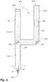
- Figure 1 shows a schematic representation of a cross section through a machining head 1 along a central axis of the machining head 1. This central axis runs in FIG Figure 1 lying in the display level from top to bottom.
- the processing head 1 belongs to a liquid jet laser processing machine (not shown further here).
- This liquid jet laser processing machine comprises a laser which can generate a laser beam, or else an input through which a laser beam generated by a separate laser can be guided into the liquid jet laser processing machine.
- the laser beam 100 is guided in the liquid jet laser processing machine to the processing head 1 in order to be coupled into a liquid jet 200 there.
- the laser beam 100 is shown in dashed lines. It runs from top to bottom along the central axis of the machining head 1 into the machining head 1 and is coupled in the machining head 1 into the liquid jet 200 which emerges from the machining head 1 at the tip of the machining head 1 along the central axis of the machining head 1. Therefore runs in the Figure 1 also the beam direction in the display plane from top to bottom.
- the processing head 1 comprises an optics unit 2 and a coupling unit 3.
- the optics unit 2 has a front end which, in the illustration shown, is at the bottom in comparison to the rest of the optics unit 2.
- the outer shell of this front end is in the form of a cylinder jacket, the rotationally symmetrical axis of the cylinder jacket shape running along the central axis of the machining head 1 or along the central axis of the optical unit 2.
- the last lens 21.4 seen in the beam direction forms a termination of the front end of the optical unit 2.
- this last lens 21.4 seen in the beam direction is the last optical element of the optical unit 2 seen in the beam direction.
- the cylindrical jacket shape of the front end of the optical unit 2 is essentially formed by a front region of a beam tube 22, in which the laser beam 100 is guided into the processing head 1 from the remaining liquid jet laser processing machine.
- the objective 20 is arranged at the front end of this beam tube 22 and serves to focus the laser beam 100 on a focus point in front of the optics unit 2.
- the diameter of this focal point is in the range from 25 ⁇ m to 40 ⁇ m.
- the coupling unit 3 comprises a main body 36, a transparent element 30, an interchangeable nozzle block 33 and an interchangeable head tip unit 35.
- the coupling unit 3 is as in FIG Figure 1 shown connected to the optics unit 2. In doing so, it encloses with its main body 36 the front end of the optical unit 2 with the objective 20 and, in the opposite direction of the beam, extends backwards behind the objective 20.
- the main body 36 has a hollow space with a circular cross section that is open on one side .
- the cavity is closed off by a tubular wall 31 with a circular cross section.
- the outside of the wall 31 facing away from the cavity likewise has a circular cross section.
- the diameter of the cross section of the outside is not the same everywhere.
- the diameter of the cross section of the outside is constant only in a region of an end of the wall 31 which faces the processing head 1 of the optical unit 2 in the assembled state. Therefore, the outside of the end of the wall 31 has a cylindrical jacket shape in this area. Seen from the end of the wall 31 facing the optics unit 2, the diameter of the cross section of the outside of the wall 31 increases first after this cylindrical-jacket-shaped area in order to then taper conically to a tip.
- the optical unit 2 has an annular groove which runs around the front end. An outer edge of this groove forms a sleeve 23.
- the sleeve 23 of the optical unit 2 has an outer side which tapers conically in the beam direction. At the front end of the sleeve 23, this outside merges into the conically tapering area of the outside of the wall 31 of the main body 36. As a result, the sleeve 23 and the main body 36 together form a cone which tapers in the beam direction.
- the cone opening angle of this cone measured between a rotationally symmetrical central axis of the cone and the outer surface of the cone, is 23 °.
- This cone opening angle can also be smaller or larger. For example, it can be 20 ° or smaller. Depending on the version, it can also be 30 °, 45 °, 60 ° or greater than 60 °.
- the element 30 transparent for the laser light of the laser beam 100.
- This transparent element 30 is disk-shaped and with its two main surfaces perpendicular to the central axis of the machining head 1 or to the central axis of the Coupling unit 3 aligned.
- One of the main surfaces of the transparent element 30 forms a large part of the bottom of the cavity of the main body 36 which is open on one side.
- the other main surface of the transparent element 30, closes off a liquid space 32 arranged in the main body 36 from the cavity.
- This liquid space 32 is also disk-shaped and is aligned with its two main surfaces perpendicular to the central axis of the coupling unit 3.
- An interchangeable nozzle block 33 closes off the liquid space 32 on the side opposite the transparent element 30.
- This interchangeable nozzle block 33 forms the nozzle for generating the liquid jet 200. It is cylindrical in its basic form and has flat ends on its two ends located on its rotationally symmetrical axis Main areas on. At one of these two ends, a ring is arranged concentrically with the basic cylinder shape, the diameter of which, measured perpendicular to the rotationally symmetrical axis, is larger than the diameter of the remaining basic cylinder shape. If the nozzle block 33 is therefore inserted in the main body 36 of the coupling unit 3, this ring forms a stop 34 and enables the nozzle block 33 to be correctly positioned in the main body 36. Because of this stop 34, the nozzle block 33 is essentially hat-shaped.
- the nozzle block 33 has a nozzle opening 37 which has a diameter of 70 ⁇ m and which runs along the rotationally symmetrical axis of the nozzle block 33.
- this main surface of the nozzle block 33 faces the liquid space 32 and the rotationally symmetrical axis of the nozzle block 33 runs along the central axis of the machining head 1 or along the central axis of the coupling unit 3 along the central axis of the machining head 1.
- the nozzle opening 37 does not extend through the entire nozzle block 33, but rather flows smoothly, viewed in the direction of the beam, into a conically opening 38, which extends through the nozzle block 33 to the main surface of the nozzle block 33, which has the stop 34.
- the nozzle block 33 enables a liquid jet 200 to be generated through the nozzle opening 37 with the liquid from the liquid space 32, said liquid jet being directed along the central axis of the machining head 1 and thus leaving the nozzle block 33 in the jet direction through the conically opening 38.
- the liquid used is water. However, a liquid other than water can also be used.
- the laser beam 100 is focused by the lens 20 of the optical unit 2 onto a focal point in front of the optical unit 2.
- the focus point is positioned such that it lies in the initial area of the nozzle opening 37.
- the laser beam 100 is focused into the liquid jet 200 generated by the nozzle opening 37 and coupled into the liquid jet 200, where it remains coupled due to total reflection on the surface of the liquid jet 200.
- the optical unit 2 has a liquid channel 51 connected to a liquid source, not shown here.
- This liquid channel 51 leads to the inside of the sleeve 23 of the optical unit 2, where it ends in an opening.
- this opening of the liquid channel 51 in the optical unit 2 lies on an opening in the end of the coupling unit 3 which faces the optical unit 2.
- This opening in the coupling unit 3 forms the entrance to a further liquid channel 42, which leads through the main body 36 of the coupling unit 3 to the liquid space 32.
- the two superimposed openings in the optical unit 2 and the coupling unit 3 form a liquid interface 50, via which the liquid space 32 can be supplied with liquid by the optical unit 2. Accordingly, the liquid jet 200 can also be supplied with liquid via the liquid interface 50.
- liquid is dispensed through the opening in the optical unit 2 and is passed into the opening in the coupling unit 3.
- the opening in the optical unit 2 is arranged on the inside of the sleeve 23, which has the shape of an inside of a cylinder jacket surface.
- the rotationally symmetrical axis of this cylindrical surface coincides with the central axis of the optical unit 2 and thus with the central axis of the machining head 1.
- This cylinder jacket surface is aligned parallel to the beam direction in the assembled state of the machining head 1.
- the opening in the coupling unit 3, on the other hand, is arranged on the outside of the end of the coupling unit 3 which faces the optics unit 2.
- This outside has a shape of the outside of a cylindrical surface, the rotationally symmetrical axis of which corresponds to the central axis of the coupling unit 3.
- This cylinder jacket surface is therefore also aligned parallel to the beam direction when the machining head 1 is mounted.
- a liquid interface surface of the liquid interface 50 is defined by the areas of the cylinder-jacket-shaped surfaces which are around those to the liquid interface 50 belonging opening in the optical unit 2 and the opening belonging to the liquid interface 50 are in the coupling unit 3.
- the liquid interface surface continuously extends from the regions of the cylindrical jacket-shaped surfaces around the openings over the region of the openings. Therefore, the liquid interface surface also lies on a cylindrical surface whose rotationally symmetrical axis corresponds to the central axis of the coupling unit 3.
- the liquid interface area is limited to the area of the openings because the liquid interface 50 is limited to this area. Nevertheless, the liquid interface surface is aligned parallel to the jet direction.
- the liquid interface 50 is at a height of the sleeve 23 of the optical unit 2 when the processing head 1 is mounted in the beam direction, the laser beam 100 passes the liquid interface 50 before it passes the lens 20 of the optical unit 2.
- the liquid interface 50 is located in front of the last lens 21.4 of the objective 20 seen in the beam direction.
- the head tip unit 35 of the coupling unit 3 has an essentially conical outer shape. In addition, it has an opening 39 in its interior, which is continuous along its longitudinal axis through the head tip unit 35 and also has a conical shape.
- the head tip unit 35 is mounted on the main body 36 of the coupling unit 3. It runs with its longitudinal axis along the central axis of the machining head 1 and, with its conical outer shape, forms the tip of the cone formed by the sleeve 23 and the main body 36.
- the conical opening 39 is oriented in its interior in such a way that it tapers in the direction of the tip of the outer shape.
- the head tip unit 35 holds the nozzle block 33 in its position in the main body 36 of the coupling unit 3 with its end facing the main body 36 of the coupling unit 3.
- the side of the opening 39 facing the nozzle block 33 is located directly in the head tip unit 35 on the conically opening 38 in the nozzle block 33.
- the opening 38 in the nozzle block 33 and the opening 39 in the head tip unit 35 form a cavity in the Machining head 1, which has a substantially rhombic cross section in a sectional plane along the central axis of the machining head 1. This cavity forms a gas storage space 40.
- the liquid jet 200 generated by the nozzle opening 37 runs through this gas storage space 40 and leaves the processing head 1 through the tapered side of the conical opening 39 in the head tip unit 35.
- the liquid jet 200 thereby touches the edge but not the tapered side of the opening 39, but leaves a small gap all around. Gas can escape from the gas storage space 40 through this gap in order to form a gas jet enveloping the liquid jet 200. Therefore, the tapered side of the conical opening 39 in the head tip unit 35 forms a gas outlet nozzle 62.
- the gas jet generated by this gas outlet nozzle 62 and enveloping the liquid jet 200 serves to stabilize the liquid jet 200 so that it is stable over a longer distance from the head tip unit 35 and becomes unstable only afterwards and disintegrates into individual drops. This enables the laser beam 100 to remain coupled into the liquid jet 200 over a longer distance.
- the optical unit 2 has a gas channel 61 connected to a gas source (not shown here).
- This gas channel 61 leads to the inside of the sleeve 23 of the optical unit 2, where it ends in an opening.
- this opening of the gas channel 61 in the optics unit 2 lies on an opening in the end of the coupling unit 3, which faces the optics unit 2.
- This opening in the coupling unit 3 forms the entrance to a further gas channel 41, which leads through the main body 36 of the coupling unit 3 and the head tip unit 35 to the opening 39 in the head tip unit 35.
- the two superimposed openings in the optical unit 2 and the coupling unit 3 form a gas interface 60, via which the gas storage space 40 can be supplied with gas by the optical unit 2. Accordingly, the gas jet can also be supplied with gas via the gas interface 60.
- a gas interface surface of the gas interface 60 is defined by the regions of the cylindrical jacket-shaped surfaces, which are around the opening in the optical unit 2 belonging to the gas interface 60 and that belonging to the gas interface 60 Opening in the coupling unit 3.
- the gas interface surface extends continuously from these surrounding areas of the cylindrical jacket-shaped areas over the area of the openings. Therefore, the gas interface surface also lies on a cylindrical surface, the rotationally symmetrical axis of which corresponds to the central axis of the coupling unit 3.
- the gas interface area is limited to the area of the openings because the gas interface 60 is limited to this area. Nevertheless, the gas interface surface is aligned parallel to the beam direction.
- the gas interface 60 Since the gas interface 60 is located at a height of the sleeve 23 of the optics unit 2 when the processing head 1 is mounted in the beam direction, the laser beam 100 passes the gas interface 60 before it passes through the lens 20 of the optics unit 2.
- the gas interface 60 like the liquid interface 50 when viewed in the beam direction, is located in front of the last lens 21.4 of the objective 20 when viewed in the beam direction.
- This arrangement of the gas interface 60 and the liquid interface 50 enables the machining head 1 to be constructed in which the outer shape of the optical unit 2 and of the coupling unit 3 as seen in the beam direction. This allows the processing head 1 to be inclined relative to an object to be processed and yet to reach the object with the stable region of the liquid jet 200 without the processing head 1 colliding with the object.
- the arrangement of the objective 20, viewed in the beam direction, after the liquid interface 50 and the gas interface 60 at the front end of the optics unit 2, allows the laser beam 100 to be focused only shortly before the nozzle opening 37.
- the objective can have a short focal length and still focus the laser beam on the focal point in the entrance area of the nozzle opening 37.
- This enables the laser beam 100 to be focused on a focus point with a small diameter.
- this construction of the machining head 1 enables the laser beam 100 to be coupled into a liquid jet 200 with a small diameter.
- a first of these sealing rings runs in front of the liquid interface 50 as seen in the jet direction, while a second of these sealing rings runs between the liquid interface 50 and the gas interface 60 and while the third of the sealing rings is arranged after the gas interface 60 in the jet direction.
- the liquid interface 50 and the gas interface 60 are separated from one another, so that no liquid can get from the liquid interface 50 to the gas interface 60 and no gas from the gas interface 60 to the liquid interface 50.
- the liquid interface 50 and the gas interface 60 are thereby also sealed to the outside, so that neither liquid nor gas can escape between the optical unit 2 and the coupling unit 3.
- Figure 2 shows similarly as already Figure 1 a schematic representation of a cross section through the machining head 1 along a central axis of the machining head 1.
- Figure 1 is in the Figure 2 shown an exploded view.
- the optical unit 2 with the sleeve 23 and the front end with the lens 20 can be seen as a separate element of the processing head 1.
- the main body 36 of the coupling unit 3 and the transparent element 30, the nozzle block 33 and the head tip unit 35 can also be recognized as separate elements.
- FIG 3 shows a schematic representation of a cross section through the nozzle block 33.
- the nozzle opening 37 is located in an insert 70 which is embedded in the corresponding main surface of the nozzle block 33.
- This insert 70 is cylindrical. In one of its two flat main surfaces, the nozzle opening 37 is arranged, which along the rotationally symmetrical axis of the insert 70 merges into a conically opening 71 in the insert 70. If the insert 70 is embedded in the remaining nozzle block 33 as shown here, the conical opening 71 of the insert 70 merges into the conical opening 38 of the nozzle block 33.
- the first aspect ie the machining head, is not based on that in the Figures 1 to 3 limited example shown.
- the outer shape of the machining head can be other than conical.
- both the optical unit and the coupling unit can be shaped differently.
- the liquid interface and the gas interface can also be arranged elsewhere and shaped differently. For example, they can be arranged at the outermost end of the end of the coupling unit facing the optical unit.
- the interface surface can, for example, also be oriented at an angle to the beam direction or lie in a plane oriented perpendicular to the beam direction.
- the course of the liquid channel and the gas channel within the optical unit and within the coupling unit can run differently.
- the gas duct is not led from the main body of the coupling unit via the head tip unit, but via the nozzle block or directly from the main body of the coupling unit to the gas storage space.
- the coupling unit does not have an exchangeable head tip unit.
- the processing head can also do without a gas storage space.
- the gas channel can be connected directly to the gas outlet nozzle, for example.
- the processing head cannot generate a gas jet enveloping the liquid jet at all. In this case, neither a gas duct, a gas interface, a gas storage space nor a gas outlet nozzle is required.
- the nozzle block is constructed differently. For example, it can be shaped differently. But it can also be made in one piece and thus without insert.
- the nozzle opening has a diameter other than 70 ⁇ m.
- the nozzle opening may be one Have diameters in the range of 20 ⁇ m to 150 ⁇ m. This diameter can also be 20 ⁇ m or smaller, or 150 ⁇ m or larger. In the same way, the diameter of the focal point of the laser beam 100 can also deviate from the range from 25 ⁇ m to 40 ⁇ m.
- Figure 4 shows a schematic representation of a cross section through a liquid jet laser processing machine 300 according to the invention.
- the cross section shown runs along the beam path of the laser beam 100. Accordingly, the beam path of the laser beam 100 essentially runs in the plane of the representation.
- the liquid jet laser processing machine 300 is shown aligned such that the top and bottom of the illustration correspond to the top and bottom of the liquid jet laser processing machine 300.
- the liquid jet laser processing machine 300 comprises a beam tube 301 which encloses the beam path of the laser beam 100.
- This jet pipe 301 has three arms 302.1, 302.2, 302.3, which are connected to one another by a branch.
- the free end of the first arm 302.1 of the jet pipe 301 is formed by a processing head 1 according to the first aspect. In the present case, this is based on the Figures 1 to 3 Machining head described in detail 1. In the present Figure 4 the processing head 1, on the other hand, is shown in a highly simplified manner, the correct proportioning of the elements shown being dispensed with.
- the free end of the second arm 302.2 of the beam tube 301 forms a termination of the beam path of the laser beam 100.
- a CCD camera 303 which is sensitive to light with the wavelength of the laser beam 100, is arranged on the inside of this termination as an image sensor.
- the free end of the third arm 302.3 of the jet pipe 301 is also closed, but has an input 304.
- the laser beam 100 generated by a laser separate from the liquid jet laser processing machine 300 is fed to the liquid jet laser processing machine 300 by means of a glass fiber, not shown here, or by means of a waveguide, not shown here.
- the liquid jet laser processing machine 300 can also comprise its own laser for generating the laser beam 100 instead of the input 304.
- the free end of the third arm 302.3 points upwards, so that the entrance 304 is open at the top. Therefore, the laser beam 100 is fed from top to bottom through the input 304 of the liquid jet laser processing machine 300. The beam direction of the laser beam 100 therefore runs from top to bottom within this free end of the third arm 302.3.
- the laser beam 100 passes through a collimation unit 305, which collimates the laser beam 100. In order to change the collimation of the laser beam 100, the collimation unit 305 can be moved in the beam direction or counter to the beam direction.
- Appropriate positioning of the collimation unit 305 can therefore, for example, perfectly collimate the laser beam 100 after the collimation unit 305, so that the light beams of the laser beam 100 after the collimation unit 305 run exactly parallel to one another.
- the collimation unit 305 can, however, also be positioned differently, so that the laser beam 100 is not perfectly collimated after the collimation unit 305, but rather that the light beams of the laser beam 100 are slightly convergent or slightly divergent to one another. Therefore, the parallelism, convergence or divergence of the light beams of the laser beam 100 after the collimation unit 305 can be adjusted as required by suitable positioning of the collimation unit 305 in the beam tube 301.
- the third arm 302.3 of the jet pipe 301 has a right-angled bend, after which the jet pipe 301 runs in the horizontal direction.
- a first mirror 306 is arranged in this bend, which reflects the laser beam 100, so that the laser beam 100 continues after the first mirror 306 in the horizontal region of the radiation tube 301.
- the first mirror 306 is driven by a motor (not shown here) and can be pivoted about a first axis 307.
- This first axis 307 is aligned horizontally and points vertically out of the display plane. Therefore, the first axis 307 is oriented perpendicular to the beam direction of the laser beam 100 before and after the first mirror 306.
- the horizontally extending region of the third arm 302.3 of the jet pipe 301 extends from the kink in the third arm 302.3 to the branching of the jet pipe 301.
- the first arm 302.1 of the jet pipe 301 runs vertically downwards and the second arm 302.2 of the jet pipe 301 vertically above.
- a second mirror 308, which reflects the laser beam 100, is arranged in the branch, so that the laser beam 100 continues to travel downward in the first arm 302.1 of the radiation tube 301 after the second mirror 308.
- the second mirror 308 is pivoted about a second axis 309 driven by a motor, not shown here. This second axis 309 lies in the plane of representation and is therefore oriented at right angles to the first axis 307.
- the beam direction of the laser beam 100 can be after the second mirror 308 can be set. This makes it possible to keep the beam direction of the laser beam 100 after the second mirror 308 exactly in the display plane as required or to tilt it slightly from the display plane towards the viewer or away from the viewer.
- the laser beam 100 in the processing head 1 is focused on a focus point by the optical unit 2.
- a position of the focal point of the laser beam 100 can therefore be set in a direction perpendicular to the plane of the representation.
- a position of the focus point in a direction perpendicular to the alignment of the first arm 302.1 of the jet pipe 301, which runs parallel to the plane of the illustration can be adjusted.
- the two mirrors 306, 308 thus enable the positioning of the laser beam 100 in the machining head 1 in a plane perpendicular to the alignment of the first arm 302.1.
- the optical unit according to the invention does not comprise any movable elements, a distance between the focal point of the laser beam 100 and the optical unit 2 depends on the collimation of the laser beam 100 immediately in front of the optical unit 2. Therefore, the positioning of the collimation unit 305 in the third arm 302.3 not only enables the collimation to be adjusted of the laser beam 100 after the collimation unit 305, but also an adjustment of the distance of the focal point of the laser beam 100 to the optics unit 2.
- the laser beam 100 is defocused on the entrance of the nozzle opening 37, so that laser light from the Laser beam 100 is reflected from the area of the nozzle around the entrance of the nozzle opening 37.
- This reflected light is fed back through the optics unit 2 into the first arm 302.2 of the beam tube 301, where it strikes the second mirror 308, which at least partially transmits the reflected light. At least parts of the reflected light therefore reach the second arm 302.2 of the beam pipe 301, at the free end of which they strike the CCD camera 303.
- the second mirror 308 can be semi-transparent, for example.
- the second mirror 308 can, for example, also reflect light in one polarization direction and transmit light in the other polarization direction.
- the laser light of the laser beam 100 can be supplied, for example, already polarized through the input 304 of the liquid jet laser processing machine 300 or else polarized in the third arm 302.1 of the beam tube 301. If the polarization of the laser light is selected appropriately, the laser beam 100 is reflected by the second mirror 308 to the processing head 1.
- a quarter-wave plate (not shown here) is installed in the first arm 302.1 of the jet pipe 301, the light of the laser beam 100, which reflects from the second mirror 308 into the first arm 302.1 of the jet pipe 301 and from the region of the nozzle, passes through around the entrance of the nozzle opening 37 is reflected back to the second mirror 308, this lambda quarter plate two times. As a result, this reflected light is polarized in the first arm 302.1. This means that it is now transmitted through the second mirror 308 and can reach the CCD camera 303.
- the CCD camera 303 can also have a suitable lens, which can be movable.
- the focal point of the laser beam 100 viewed in the beam direction, is positioned on a plane defined by the wall of the exchangeable nozzle block 33 or the nozzle, which faces the optical unit 2, and is positioned in this plane in the entrance of the nozzle opening 37, then the Laser beam 100 is coupled into the liquid jet 200 generated by the nozzle.
- the liquid jet 200 is a water jet.
- any liquid other than water to generate the liquid jet 200.
- FIGS. 5a to 5f illustrate an embodiment of the method according to the invention for focusing the laser beam 100 into the nozzle opening 37 of the nozzle of the liquid jet laser processing machine 300 in order to couple the laser beam 100 into the liquid jet 200 generated by the nozzle opening 37.
- the laser beam 100 is defocused onto the entrance of the nozzle opening 37 by positioning the collimation unit 305 in the third arm 302.3 of the jet pipe 301 in such a way that the focal point is located behind the nozzle when viewed in the beam direction. While the nozzle is illuminated by the defocused laser beam 100, the CCD camera 303 captures the area of the nozzle around the entrance of the nozzle opening 37.
- Figure 5a shows a schematic representation of such a recording, in which the entrance of the nozzle opening 37 can be seen as an unilluminated, dark spot 337.
- this marking 338 is supplemented by two straight lines 339.1, 339.2 intersecting at right angles in the center of the spot 337.
- the marking is stored in a buffer memory so that it can be transferred to other images of the CCD camera 303.
- the laser beam 100 is moved to a position on the region of the nozzle around the entrance of the nozzle opening 37 with reduced power of the laser focused by positioning the collimation unit 305 accordingly in the third arm 302.3 of the jet pipe 301.
- the focusing of the laser beam 100 is checked in a step-by-step procedure by taking a picture with the CCD camera 303 until the focal point 340 of the laser beam 100 has a minimal size in the image.
- FIG Figure 5c schematically shown, the marking 338 created in the first two steps of the method being transferred to the image.
- the brightly illuminated focus point 340 is shown as a dark point.
- the focal point 340 of the laser beam 100 is positioned on the first of the two intersecting lines 339.1 of the marking 338 in a fourth step. Since a movement of the focus point 340 along the second of the two intersecting lines 339.2 is achieved by a pivoting movement of the second mirror 308 about the second axis 309, it is sufficient to set a suitable orientation of the second mirror 308 for this purpose.
- this fourth step it is possible to proceed iteratively by checking whether the focus point 304 of the laser beam 100 is really positioned on the first line 339.1 of the mark 338 by recording an image with the CCD camera 303 and transferring the mark 338 to this figure. The orientation of the second mirror 308 about the second axis 309 is then stored as the first positioning parameter.
- the focal point 340 of the laser beam 100 is positioned on the second of the two intersecting lines 339.2 of the marking 338. Since a movement of the focal point 340 along the first of the two intersecting lines 339.1 is achieved by a pivoting movement of the first mirror 306 about the first axis 307, it is sufficient to set a suitable orientation of the first mirror 306 for this purpose.
- the second mirror 308 is pivoted somewhat about the second axis 309 at the beginning of the fifth step, so that the focus point 340 of the laser beam 100 is always moved through next to the entrance of the nozzle opening 37 when the first mirror 306 moves about the first axis 307 becomes.
- the second mirror 308 is oriented around the second axis 309 according to the first position parameter and the first mirror 306 is oriented around the first axis 307 according to the second position parameter.
- the focal point 340 of the laser beam 100 is positioned in the entrance of the nozzle opening 37 and the laser beam 100 is coupled into the liquid jet 200 generated by the nozzle opening 37. Since the focus point 340 of the laser beam 100 is positioned in this way, no light from the laser beam 100 is reflected from the region of the nozzle around the entrance of the nozzle opening to the CCD camera 303, the focus point 304 is not closed in an image recorded by the CCD camera 303 detect. Accordingly, in the Figure 5f the focus point 340 of the laser beam 100 is only shown as a dashed line in the center of the marking 338.
- the liquid jet laser processing machine 300 can comprise a memory for storing the first and second positioning parameters and an intermediate memory for storing the marking.
- the liquid jet laser processing machine 300 can include a control unit for controlling the positioning of the collimation unit 305 in the third arm 302.3 of the jet pipe 301 and for controlling the orientation of the first and second mirrors 306, 308 about the first and second axes 307, 309, respectively.
- the memory, the intermediate memory or the control unit are formed separately from the liquid jet laser processing machine 300.
- the memory, the buffer store and the control unit can be formed by a computer to which the liquid jet laser processing machine is connected.
- the invention is not based on the liquid jet laser processing machine 300 and that based on FIG Figures 5a - 5f limited procedures described in detail.
- the liquid jet laser processing machine 300 can have a different processing head.
- the jet pipe and the arms of the jet pipe can also be used be trained differently.
- the jet pipe can have no branching, so that it also has no arms that start from a branching.
- the two mirrors can also be arranged differently, oriented differently and pivoted about differently oriented axes.
- the liquid jet laser processing machine does not have a CCD camera, but rather a different type of two-dimensional image sensor. It is also not necessary for the entire collimation unit to be movable in the beam direction or counter to the beam direction.
- the collimation unit also has only individual movable elements.
- the optical unit can be assigned to the processing head or can be designed separately from the processing head.
- the method for focusing the laser beam into the nozzle opening of the nozzle of the liquid jet laser processing machine in order to couple the laser beam into the liquid jet generated by the nozzle opening is not limited to the method described in detail.
- the method can include additional steps.
- some of the steps described can be modified or omitted. For example, there is no need to add two intersecting lines to the marking. This step can be deleted without replacement or replaced by a step in which other lines are added to the marking.
- a liquid jet laser processing machine which simplifies the coupling of the laser beam into the liquid jet.
- a method for focusing a laser beam into a nozzle opening of a nozzle in such a liquid jet laser processing machine is created, which simplifies the coupling of the laser beam into the liquid jet.
Landscapes
- Engineering & Computer Science (AREA)
- Physics & Mathematics (AREA)
- Optics & Photonics (AREA)
- Plasma & Fusion (AREA)
- Mechanical Engineering (AREA)
- Laser Beam Processing (AREA)
Description
- Die Erfindung betrifft eine Flüssigkeitsstrahl-Laserbearbeitungsmaschine mit einem Bearbeitungskopf zum Einkoppeln eines Laserstrahls in einen Flüssigkeitsstrahl. Der Bearbeitungskopf weist eine Düse mit einer Düsenöffnung zur Erzeugung des Flüssigkeitsstrahls auf. Der Laserstrahl ist durch eine Fokussiereinrichtung in einen Eingang der Düsenöffnung fokussierbar, um den Laserstrahl in den Flüssigkeitsstrahl einzukoppeln. Die Flüssigkeitsstrahl-Laserbearbeitungsmaschine umfasst einen zweidimensionalen Bildsensor zum Abbilden eines Bereichs der Düse um den Eingang der Düsenöffnung herum.
- Es sind Laserbearbeitungsvorrichtungen bekannt, bei welchen der Laserstrahl in einen dünnen Wasserstrahl eingekoppelt wird, um den Laserstrahl wie in einem optischen Wellenleiter zur Materialbearbeitungsstelle zu führen. Solche Laserbearbeitungsvorrichtungen haben den Vorteil, dass die Energie des Lasers über die Länge des Wasserstrahls auf den Querschnitt des Wasserstrahls konzentriert ist. Entsprechend muss der Fokuspunkt des Laserstrahls bei variierendem Abstand zur Materialbearbeitungsstelle nicht ständig nachgeführt werden. Solche Vorrichtungen haben ausserdem den Vorteil, dass das zu bearbeitende Material durch den Wasserstrahl kontinuierlich gekühlt werden kann.
- Um einen dünnen Wasserstrahl zu erzeugen und um den Laserstrahl in diesen Wasserstrahl einkoppeln zu können, weisen derartige Laserbearbeitungsvorrichtungen einen Bearbeitungskopf auf. Dieser Bearbeitungskopf kann unterschiedlich aufgebaut und geformt sein. So kann er beispielsweise in der restlichen Laserbearbeitungsvorrichtung eingelassen sein, sodass der Wasserstrahl mit dem eingekoppelten Laserstrahl quasi aus einer Wand der Laserbearbeitungsvorrichtung austritt. In diesem Fall kann ein zu bearbeitendes Objekt vor dieser Wand relativ zum Bearbeitungskopf bewegt werden, damit der Wasserstrahl mit dem eingekoppelten Laserstrahl die zu bearbeitenden Stellen des Objekts erreichen kann. Es besteht aber auch die Möglichkeit, dass der Bearbeitungskopf ein freies, distales Ende der Laserbearbeitungsvorrichtung bildet oder an einem freien, distalen Ende eines bewegbaren Arms der Laserbearbeitungsvorrichtung angeordnet ist. Dies ermöglicht es, dass der Wasserstrahl mit dem eingekoppelten Laserstrahl über ein zu bearbeitendes Objekt bewegt werden kann, um die zu bearbeitenden Stellen mit dem Wasserstrahl zu erreichen.
- Unabhängig davon, wie der Bearbeitungskopf genau geformt ist, ist er in der Regel durch eine Optikeinheit sowie eine Kopplungseinheit gebildet. Dabei umfasst die Optikeinheit wenigstens ein optisches Element wie beispielsweise eine Linse oder eine Linsengruppe, um den Laserstrahl zu fokussieren. Die Kopplungseinheit hingegen umfasst eine Düse mit einer Düsenöffnung zur Erzeugung eines Flüssigkeitsstrahls. Dabei sind die Optikeinheit und die Kopplungseinheit im Bearbeitungskopf derart zueinander angeordnet, dass die Optikeinheit den Laserstrahl derart in den Flüssigkeitsstrahl fokussieren kann, dass der Laserstrahl in den Flüssigkeitsstrahl eingekoppelt wird.
- Ein Beispiel eines derartigen Bearbeitungskopfs ist in der
EP 1 833 636 B1 der Synova S.A. beschrieben. Dieser Bearbeitungskopf umfasst eine Kopplungseinheit zum Erzeugen eines Flüssigkeitsstrahls mittels einer Flüssigkeitsdüse. Weiter umfasst dieser Bearbeitungskopf eine Optikeinheit, mittels welcher ein Laserstrahl in den Flüssigkeitskanal der Flüssigkeitsdüse fokussiert wird, um den Laserstrahl in den Flüssigkeitsstrahl zu koppeln. Die Kopplungseinheit umfasst eine Fassung, ein Fensterelement sowie ein Verschlussteil. Auf der Oberseite der Fassung ist eine konische Öffnung für die Optikeinheit angeordnet. Am unteren Ende dieser konischen Öffnung weist die Fassung eine Schulter auf, an welcher das Fensterelement an seiner oberen Seite anliegt. Das Verschlussteil ist auf der Unterseite des Fensterelements angeordnet und schliesst einen dünnen, scheibenförmigen Zwischenraum zwischen dem Fensterelement und dem Verschlussteil nach unten ab. Dieser Zwischenraum dient als Flüssigkeitszuführleitung für die Flüssigkeitsdüse, welche in eine Ausnehmung in der oberen, dem Zwischenraum zugewandten Seite des Verschlussteils eingesetzt ist. Diese Flüssigkeitsdüse hat einen zentralen Kanal, welcher einen feinen Flüssigkeitsstrahl bildet, in den die Laserstrahlung eingekoppelt wird. - Der Nachteil solcher Bearbeitungsköpfe ist, dass sie senkrecht zum Flüssigkeitsstrahl eine grosse Breite aufweisen. Zudem ist der Flüssigkeitsstrahl nur über eine beschränkte Länge stabil. Danach zerperlt er in einzelne Tropfen, welche über eine Falllänge in leicht abgeflachte, annähernd kugelförmige Tropfen übergehen. Da nur der stabile Flüssigkeitsstrahl als Lichtleiter für den Laserstrahl dienen kann, ist die verfügbare Distanz von der Flüssigkeitsdüse bis zur zu bearbeitenden Stelle beschränkt. Dies führt dazu, dass mit solchen Bearbeitungsköpfen zwar im Wesentlichen flächige Bearbeitungsstücke problemlos bearbeitet werden können. Sobald aber im Rahmen einer dreidimensionalen Bearbeitung von Objekten auch schwieriger zugängliche Stellen bearbeitet werden sollen, sind solche Bearbeitungsköpfe ungeeignet. In diesem Fall würden sie aufgrund ihrer Breite gegen das zu bearbeitende Objekt stossen, wenn das Objekt genügend nah am Bearbeitungskopf gehalten wird, um mit einem stabilen Flüssigkeitsstrahl mit eingekoppeltem Laserstrahl die zu bearbeitende Stelle zu erreichen.
- Ein erster Aspekt, nicht direkt Teil der Erfindung, betrifft einen Bearbeitungskopf, der eine dreidimensionale Bearbeitung von Objekten ermöglicht. Gemäss diesem ersten Aspekt ist im mit der Optikeinheit verbundenen Zustand der Kopplungseinheit die Flüssigkeitsschnittstelle in Strahlrichtung gesehen vor dem in Strahlrichtung gesehen letzten optischen Element der Optikeinheit angeordnet.
- Dabei bedeutet der Begriff "Flüssigkeitsschnittstelle" die Stelle, an welcher Flüssigkeit von der Optikeinheit an die Kopplungseinheit weitergeleitet wird, um den Flüssigkeitsraum mit Flüssigkeit zu versorgen. Hierzu weist die Optikeinheit eine Öffnung auf, aus welcher Flüssigkeit für den Flüssigkeitsraum aus der Optikeinheit austreten kann. Zudem weist die Kopplungseinheit eine Öffnung auf, in welche Flüssigkeit für den Flüssigkeitsraum geleitet werden kann. Diese beiden Öffnungen sind im mit der Optikeinheit verbundenen Zustand der Kopplungseinheit derart zueinander angeordnet, dass aus der Öffnung in der Optikeinheit austretende Flüssigkeit in die Öffnung in der Kopplungseinheit fliessen kann. Dadurch bilden die beiden Öffnungen zusammen mit einem allenfalls zwischen der Optikeinheit und der Kopplungseinheit eingeschlossenen Bereich, in welchem aus der Öffnung in der Optikeinheit austretende Flüssigkeit zur Öffnung in der Kopplungseinheit geleitet wird, die Flüssigkeitsschnittstelle. Dabei können die beiden Öffnungen im mit der Optikeinheit verbundenen Zustand der Kopplungseinheit einander zugewandt direkt aufeinanderliegen. In diesem Fall bilden die beiden aufeinander liegenden Öffnungen die Flüssigkeitsschnittstelle. Die beiden Öffnungen können aber auch seitlich etwas zueinander versetzt angeordnet sein. Unabhängig von der Anordnung der beiden Öffnungen können die Optikeinheit und die Kopplungseinheit zudem einen Bereich einschliessen, in welchem aus der Öffnung in der Optikeinheit austretende Flüssigkeit zur Öffnung in der Kopplungseinheit geleitet wird. Dieser Bereich kann beispielsweise durch eine oder mehrere zwischen der Optikeinheit und der Kopplungseinheit angeordnete Dichtungen begrenzt sein. In diesem Fall erstreckt sich die Flüssigkeitsschnittstelle über diesen Bereich sowie die beiden Öffnungen.
- Das in Strahlrichtung gesehen letzte optische Element der Optikeinheit ist das optische Element, durch welches der Laserstrahl als letztes in der Optikeinheit geleitet wird, bevor er die Optikeinheit verlässt und in der Kopplungseinheit in den Flüssigkeitsstrahl eingekoppelt wird. Daher kann es sich bei diesem letzten optischen Element beispielsweise um eine Linse oder um eine Linsengruppe handeln, mittels welcher der Laserstrahl fokussiert werden kann. Es kann sich beim in Strahlrichtung gesehen letzten optischen Element aber auch um ein Fenster handeln, welches die Optikeinheit nach aussen abschliesst und selbst keine fokussierenden Eigenschaften aufweist. Unabhängig von der konkreten Ausführungsform des in Strahlrichtung gesehen letzten optischen Elements ist die Flüssigkeitsschnittstelle in Strahlrichtung gesehen vor diesem optischen Element angeordnet, sodass ein durch die Optikeinheit geleiteter Laserstrahl zuerst neben der Flüssigkeitsschnittstelle vorbei oder durch die Flüssigkeitsschnittstelle hindurch geleitet wird, bevor er das letzte optische Element der Optikeinheit passiert. Dabei ist für die Lösung unerheblich, ob die Kopplungseinheit direkt mit der Optikeinheit verbindbar ist, oder ob die Kopplungseinheit über ein Zwischenelement mit der Optikeinheit verbindbar ist. Genauso ist unerheblich, wie die Optikeinheit und die Kopplungseinheit genau ausgebildet sind. So kann die Optikeinheit beispielsweise als separate Einheit an einer Laserbearbeitungsvorrichtung anbringbar sein. Dadurch kann ein Laserstrahl, welcher von einem zur Laserbearbeitungsvorrichtung gehörenden Laser erzeugt wurde, durch die Optikeinheit geleitet werden. Von der Optikeinheit kann dieser Laserstrahl fokussiert und in den Flüssigkeitsstrahl eingekoppelt werden, welcher von der an der Optikeinheit angebrachten Kopplungseinheit erzeugt wird. Die Optikeinheit kann aber beispielsweise auch den Endbereich eines Strahlenrohrs einer Laserbearbeitungsvorrichtung bilden, in welchem der vom zur Laserbearbeitungsvorrichtung gehörenden Laser erzeugte Laserstrahl geführt ist. In diesem Fall kann das Strahlenrohr Teil der Laserbearbeitungsvorrichtung sein und in seinem Endbereich in die Optikeinheit übergehen. Dabei kann die Kopplungseinheit beispielsweise aussen am Endbereich des Strahlenrohrs, welcher Teil der Optikeinheit ist, befestigt sein.
- Dieser erste Aspekt hat den Vorteil, dass der Bearbeitungskopf kleiner konstruiert werden kann. Zudem kann der Bearbeitungskopf im Bereich, wo der Flüssigkeitsstrahl mit dem eingekoppelten Laserstrahl den Bearbeitungskopf verlässt, schmaler gebaut werden. Dadurch können mit dem Bearbeitungskopf schwierig zugängliche Stellen einfacher mit einem stabilen Flüssigkeitsstrahl und einem darin eingekoppelten Laserstrahl erreicht werden. Entsprechend wird dadurch auch eine dreidimensionale Bearbeitung von Objekten erleichtert.
- Vorteilhafterweise für diesen ersten Aspekt weist im mit der Optikeinheit verbundenen Zustand der Kopplungseinheit die Flüssigkeitsschnittstelle eine Flüssigkeitsschnittstellenfläche auf, welche in einem Winkel zu einer senkrecht zur Strahlrichtung ausgerichteten Ebene ausgerichtet ist. Dabei verläuft die Flüssigkeitsschnittstellenfläche durch die Flüssigkeitsschnittstelle und damit zwischen der die Öffnung in der Optikeinheit umgebenden Oberfläche der Optikeinheit und der die Öffnung in der Kopplungseinheit umgebenden Oberfläche der Kopplungseinheit. Wenn daher die Öffnung in der Optikeinheit direkt auf der Öffnung der Kopplungseinheit liegt, sodass die von der Optikeinheit zur Kopplungseinheit geleitete Flüssigkeit zur Versorgung des Flüssigkeitsraums direkt von der Öffnung in der Optikeinheit in die Öffnung der Kopplungseinheit fliesst, so ist die Flüssigkeitsschnittstellenfläche durch den um die beiden Öffnungen liegende Bereich der aufeinanderliegenden Oberflächen der Optikeinheit und der Kopplungseinheit definiert und verläuft im Bereich, wo die entsprechenden Oberflächen der Optikeinheit und der Kopplungseinheit aufgrund der Öffnungen fehlen, stetig weiter. Dabei ist unbedeutend, ob diese um die beiden Öffnungen liegenden Bereiche der Oberflächen auf die Flüssigkeitsschnittstelle begrenzt sind, oder ob sie bis unmittelbar ausserhalb der Flüssigkeitsschnittstelle reichen. Wenn die Öffnung in der Optikeinheit hingegen nicht direkt auf der Öffnung der Kopplungseinheit liegt und die aus der Öffnung in der Optikeinheit austretende Flüssigkeit zur Versorgung des Flüssigkeitsraums durch einen zwischen der Optikeinheit und der Kopplungseinheit eingeschlossenen Bereich zur Öffnung in der Kopplungseinheit geleitet wird, so verläuft die Flüssigkeitsschnittstellenfläche zwischen dem um die Öffnung in der Optikeinheit liegenden Bereich der Oberfläche der Optikeinheit und dem um die Öffnung in der Kopplungseinheit liegenden Bereich der Oberfläche der Kopplungseinheit. Wenn ein Abstand zwischen der Oberfläche der Optikeinheit und der Oberfläche der Kopplungseinheit im Bereich um die Öffnungen konstant ist und die beiden Oberflächen in diesem Bereich somit parallel zueinander verlaufen, so verläuft die Flüssigkeitsschnittstellenfläche parallel zur Oberfläche der Optikeinheit und parallel zur Oberfläche der Kopplungseinheit zwischen diesen beiden Oberflächen und verläuft im Bereich, wo die entsprechenden Oberflächen der Optikeinheit und der Kopplungseinheit aufgrund der Öffnungen fehlen, stetig weiter. Dabei ist unbedeutend, ob diese um die beiden Öffnungen liegenden Bereiche der Oberflächen auf die Flüssigkeitsschnittstelle begrenzt sind, oder ob sie bis unmittelbar ausserhalb der Flüssigkeitsschnittstelle reichen. Wenn hingegen die Oberfläche der Optikeinheit in einem Winkel zu der Oberfläche der Kopplungseinheit verläuft, so dass sich ein senkrecht zu den Oberflächen gemessener Abstand zwischen den beiden Oberflächen innerhalb der Flüssigkeitsschnittstelle ändert, so verläuft die Flüssigkeitsschnittstellenfläche zwischen diesen beiden Oberflächen. Dabei schliesst die Flüssigkeitsschnittstellenfläche einen gleichen Winkel zur Oberfläche der Optikeinheit und zur Oberfläche der Kopplungseinheit ein und verläuft im Bereich, wo die entsprechenden Oberflächen der Optikeinheit und der Kopplungseinheit aufgrund der Öffnungen fehlen, stetig weiter. Dabei ist unbedeutend, ob diese um die beiden Öffnungen liegenden Bereiche der Oberflächen auf die Flüssigkeitsschnittstelle begrenzt sind, oder ob sie bis unmittelbar ausserhalb der Flüssigkeitsschnittstelle reichen.
- Da sowohl der um die Öffnung in der Optikeinheit liegende Bereich der Oberfläche der Optikeinheit als auch der um die Öffnung in der Kopplungseinheit liegende Bereich der Oberfläche der Kopplungseinheit gekrümmt sein kann, kann auch die Flüssigkeitsschnittstellenfläche gekrümmt sein. So kann beispielsweise die Kopplungseinheit einen zylinderförmigen Bereich aufweisen, auf dessen radialer Aussenfläche die Öffnung für die Versorgung des Flüssigkeitsraums mit Flüssigkeit angeordnet ist. Zudem kann die Optikeinheit beispielsweise eine Öffnung mit kreisförmigem Querschnitt aufweisen, in welche der zylinderförmige Bereich der Kopplungseinheit geschoben werden kann, um die Kopplungseinheit mit der Optikeinheit zu verbinden. In diesem Fall kann die Öffnung in der Optikeinheit, aus welcher Flüssigkeit für den Flüssigkeitsraum aus der Optikeinheit austreten kann, auf der Innenseite der Öffnung mit kreisförmigem Querschnitt angeordnet sein. Da die Flüssigkeitsschnittstelle somit auf dem zylinderförmigen Bereich der Kopplungseinheit liegt, folgt auch die Flüssigkeitsschnittstellenfläche der Form des zylinderförmigen Bereichs der Kopplungseinheit. Damit ist die Flüssigkeitsschnittstellenfläche in diesem Fall gekrümmt.
- Dass die Flüssigkeitsschnittstellenfläche in einem Winkel zur senkrecht zur Strahlrichtung ausgerichteten Ebene ausgerichtet ist, bedeutet, dass innerhalb der Flüssigkeitsschnittstelle bei jedem Punkt der Flüssigkeitsschnittstellenfläche die Normale auf diesen Punkt einen Winkel zur Strahlrichtung einschliesst und damit nicht parallel zur Strahlrichtung ausgerichtet ist. Dies hat den Vorteil, dass die Flüssigkeitsschnittstelle auf einfache Art und Weise abgedichtet werden kann, wenn die Kopplungseinheit zur Verbindung mit der Optikeinheit entgegen der Strahlrichtung zur Optikeinheit bewegbar und damit auf einfache Art und Weise mit der Optikeinheit verbindbar ausgebildet ist. Wenn dabei die Flüssigkeitsschnittstellenfläche in einem Winkel zur Bewegungsrichtung der Kopplungseinheit ausgerichtet ist, werden bei der Verbindung der Kopplungseinheit mit der Optikeinheit die Öffnung in der Kopplungseinheit und die Öffnung in der Optikeinheit nicht in Richtung der Normalen des um die Öffnung in der Optikeinheit liegenden Bereichs der Oberfläche der Optikeinheit und der Normalen des um die Öffnung in der Kopplungseinheit liegenden Bereichs der Oberfläche der Kopplungseinheit, sondern in seitliche Richtung aufeinander zu bewegt. Dadurch kann die Flüssigkeitsschnittstelle einfacher abgedichtet werden.
- In einer bevorzugten Variante dieses ersten Aspekts verläuft die Flüssigkeitsschnittstellenfläche parallel zur Strahlrichtung. Dies bedeutet, dass innerhalb der Flüssigkeitsschnittstelle bei jedem Punkt der Flüssigkeitsschnittstellenfläche die Normale auf diesen Punkt in einer senkrecht zur Strahlrichtung ausgerichteten Ebene liegt. Dies hat den Vorteil, dass die Flüssigkeitsschnittstelle auf einfache Art und Weise abgedichtet werden kann, wenn die Kopplungseinheit zur Verbindung mit der Optikeinheit entgegen der Strahlrichtung zur Optikeinheit bewegbar und damit auf einfache Art und Weise mit der Optikeinheit verbindbar ausgebildet ist, weil die Flüssigkeitsschnittstellenfläche dabei parallel zur Bewegungsrichtung der Kopplungseinheit ausgerichtet ist und entsprechend die Öffnung in der Kopplungseinheit entlang des um diese Öffnung liegenden Bereichs der Oberfläche der Kopplungseinheit vor die Öffnung in der Optikeinheit geschoben wird. Um diesen Vorteil zu erreichen, spielt es keine Rolle, ob die Flüssigkeitsschnittstellenfläche innerhalb der Flüssigkeitsschnittstelle ebenartig flach oder gekrümmt ist. So kann die Kopplungseinheit beispielsweise einen zylinderförmigen Bereich aufweisen, auf dessen radialer Aussenfläche die Öffnung für die Versorgung des Flüssigkeitsraums mit Flüssigkeit angeordnet ist, während die Optikeinheit eine Öffnung mit kreisförmigem Querschnitt aufweist, in welche der zylinderförmige Bereich der Kopplungseinheit entgegen der Strahlrichtung geschoben werden kann, um die Kopplungseinheit mit der Optikeinheit zu verbinden. In diesem Fall kann die Öffnung in der Optikeinheit, aus welcher Flüssigkeit für den Flüssigkeitsraum aus der Optikeinheit austreten kann, auf der Innenseite der Öffnung mit kreisförmigem Querschnitt angeordnet sein. Damit ist die Flüssigkeitsschnittstellenfläche in diesem Fall gekrümmt. Es besteht aber beispielsweise auch die Möglichkeit, dass die Kopplungseinheit einen Bereich mit quadratischem Querschnitt aufweist, wobei die Öffnung für die Versorgung des Flüssigkeitsraums mit Flüssigkeit auf einer der vier flachen Aussenseiten dieses Bereichs angeordnet ist. Dabei kann die Optikeinheit eine Öffnung mit ebenfalls quadratischem Querschnitt aufweisen, in welche der Bereich der Kopplungseinheit entgegen der Strahlrichtung geschoben werden kann, um die Kopplungseinheit mit der Optikeinheit zu verbinden. In diesem Fall kann die Öffnung in der Optikeinheit, aus welcher Flüssigkeit für den Flüssigkeitsraum aus der Optikeinheit austreten kann, auf der Innenseite der Öffnung mit quadratischem Querschnitt auf einer der vier flachen Seiten angeordnet sein. Damit ist die Flüssigkeitsschnittstellenfläche in diesem Fall ebenartig flach.
- Alternativ dazu besteht aber auch die Möglichkeit, dass im mit der Optikeinheit verbundenen Zustand der Kopplungseinheit die Flüssigkeitsschnittstelle eine Flüssigkeitsschnittstellenfläche aufweist, welche zumindest in einem Bereich parallel zur senkrecht zur Strahlrichtung ausgerichteten Ebene ausgerichtet ist.
- Vorteilhafterweise für diesen ersten Aspekt weist die Kopplungseinheit wenigstens einen Flüssigkeitskanal auf, welcher die Flüssigkeitsschnittstelle mit dem Flüssigkeitsraum verbindet. Dies hat den Vorteil, dass der Flüssigkeitsraum auf einfache Art und Weise mit Flüssigkeit versorgt werden kann, indem die von der Optikeinheit übergebene Flüssigkeit in die Öffnung in der Kopplungseinheit geleitet wird, in welche Flüssigkeit für den Flüssigkeitsraum geleitet werden kann, um von dort durch den Flüssigkeitskanal zum Flüssigkeitsraum geleitet zu werden.
- Alternativ dazu besteht aber auch die Möglichkeit, dass die Kopplungseinheit keinen derartigen Flüssigkeitskanal aufweist, da der Flüssigkeitsraum andersartig mit Flüssigkeit versorgt wird. Dies kann beispielsweise der Fall sein, wenn die Öffnung in der Kopplungseinheit, durch welche Flüssigkeit für den Flüssigkeitsraum geleitet werden kann, direkt mit dem Flüssigkeitsraum verbunden ist. Eine derartige Alternative hat den Vorteil, dass der Bearbeitungskopf kompakter konstruiert werden kann, wodurch mit dem Bearbeitungskopf schwierig zugängliche Stellen einfacher erreicht werden können und eine dreidimensionale Bearbeitung von Objekten vereinfacht wird.
- Bevorzugt für diesen ersten Aspekt verjüngt sich die Kopplungseinheit in eine Richtung, wobei diese Richtung im mit der Optikeinheit verbundenen Zustand der Kopplungseinheit der Strahlrichtung entspricht. Dadurch nimmt die quer zur Strahlrichtung gemessene Breite des Bearbeitungskopfs zur Stelle des Bearbeitungskopfs hin ab, an welcher der von der Düsenöffnung erzeugbare Flüssigkeitsstrahl den Bearbeitungskopf verlässt. Dadurch können mit dem Bearbeitungskopf auch schwierig zugängliche Stellen einfacher erreicht werden, was eine dreidimensionale Bearbeitung von Objekten vereinfacht.
- Alternativ dazu besteht aber auch die Möglichkeit, dass sich die Kopplungseinheit nicht in eine Richtung verjüngt, welche im mit der Optikeinheit verbundenen Zustand der Kopplungseinheit der Strahlrichtung entspricht. Eine derartige Alternative kann den Vorteil haben, dass der Bearbeitungskopf einfacher konstruiert und somit kostengünstiger hergestellt werden kann.
- Falls sich die Kopplungseinheit in eine Richtung verjüngt, wobei diese Richtung im mit der Optikeinheit verbundenen Zustand der Kopplungseinheit der Strahlrichtung entspricht, ist die Verjüngung vorteilhafterweise kegelmantelförmig. Dies hat den Vorteil, dass die Verjüngung in Strahlrichtung gesehen konstant gleichmässig ist. Dadurch kann der Bearbeitungskopf problemlos dem Kegelöffnungswinkel der kegelmantelförmigen Verjüngung entsprechend relativ zu einer zu bearbeitenden Fläche geneigt werden. Dies erleichtert die Erreichbarkeit von schwierig zugänglichen Stellen und vereinfacht damit die dreidimensionale Bearbeitung von Objekten.
- Alternativ dazu besteht aber auch die Möglichkeit, dass die Verjüngung eine andere Form als eine Kegelmantelform aufweist.
- Falls sich die Kopplungseinheit in eine Richtung kegelmantelförmig verjüngt, wobei diese Richtung im mit der Optikeinheit verbundenen Zustand der Kopplungseinheit der Strahlrichtung entspricht, weist die kegelmantelförmige Verjüngung vorzugsweise einen zwischen einer rotationssymmetrischen Mittelachse der Kegelmantelform und der Aussenfläche der Kegelmantelform gemessenen Kegelöffnungswinkel von höchstens 60°, höchstens 45°, höchstens 30°, insbesondere von höchstens 20° auf. Dies hat den Vorteil, dass schwierig zugängliche Stellen optimal erreicht werden können, was eine dreidimensionale Bearbeitung von Objekten vereinfacht.
- Als Alternative dazu kann die kegelmantelförmige Verjüngung aber auch einen Kegelöffnungswinkel von mehr als 20° bzw. mehr als 30°, mehr als 45° oder mehr als 60° aufweisen. Dies hat den Vorteil, dass die Konstruktion der Kopplungseinheit vereinfacht wird.
- Bevorzugt für diesen ersten Aspekt weist die Kopplungseinheit eine Gasaustrittsdüse auf, um einen den Flüssigkeitsstrahl umhüllenden Gasstrahl zu formen. Dies hat den Vorteil, dass die Länge, über welcher der Flüssigkeitsstrahl stabil ist, grösser ist. Da der Laserstrahl nur im stabilen Flüssigkeitsstrahl eingekoppelt bleibt, kann dadurch der mögliche Abstand des Bearbeitungskopfs von einer zu bearbeitenden Stelle erhöht werden. Entsprechend können dadurch mit dem Bearbeitungskopf schwierig zugängliche Stellen einfacher bearbeitet werden, was die dreidimensionale Bearbeitung von Objekten vereinfacht.
- Als Alternative dazu kann die Kopplungseinheit auch keine Gasaustrittsdüse aufweisen, um einen den Flüssigkeitsstrahl umhüllenden Gasstrahl zu formen. Eine derartige Alternative hat den Vorteil, dass der Bearbeitungskopf einfacher konstruiert und entsprechend kostengünstiger hergestellt werden kann. Zudem wird dadurch die Wartung des Bearbeitungskopfs vereinfacht.
- Falls die Kopplungseinheit eine Gasaustrittsdüse aufweist, um einen den Flüssigkeitsstrahl umhüllenden Gasstrahl zu formen, so weist die Kopplungseinheit zudem bevorzugt einen Gasstauraum auf, welcher im mit der Optikeinheit verbundenen Zustand der Kopplungseinheit in Strahlrichtung gesehen nach der Düsenöffnung angeordnet ist. Ein solcher Gasstauraum hat den Vorteil, dass die Erzeugung eines den Flüssigkeitsstrahl umhüllenden Gasstrahls vereinfacht wird, welcher die Länge vergrössert, über die der Flüssigkeitsstrahl stabil ist.
- Alternativ dazu besteht aber auch die Möglichkeit, dass die Kopplungseinheit keinen derartigen Gasstauraum aufweist. Dies hat den Vorteil, dass die Kopplungseinheit einfacher konstruiert werden kann.
- Falls die Kopplungseinheit eine Gasaustrittsdüse aufweist, um einen den Flüssigkeitsstrahl umhüllenden Gasstrahl zu formen, so ist vorzugsweise im mit der Optikeinheit verbundenen Zustand der Kopplungseinheit die Gasaustrittsdüse von der Düsenöffnung her gesehen in Strahlrichtung angeordnet. Dabei kann die Gasaustrittsdüse von der Düsenöffnung her gesehen in Strahlrichtung direkt nach der Düsenöffnung angeordnet sein. Es besteht aber auch die Möglichkeit, dass beispielsweise ein allenfalls vorhandener Gasstauraum zwischen der Düsenöffnung und der Gasaustrittsdüse angeordnet ist. In diesem Fall kann der durch die Düsenöffnung erzeugbare Flüssigkeitsstrahl in Strahlrichtung durch den Gasstauraum verlaufend durch die Gasaustrittsdüse aus der Kopplungseinheit austreten. Der Vorteil der Anordnung der Gasaustrittsdüse von der Düsenöffnung her gesehen in Strahlrichtung ist, dass der durch die Düsenöffnung erzeugbare Flüssigkeitsstrahl durch die Gasaustrittsdüse aus der Kopplungseinheit austreten kann, sodass mit der Gasaustrittsdüse ein den Flüssigkeitsstrahl optimal umhüllender Gasstrahl erzeugt werden kann.
- Alternativ dazu besteht aber auch die Möglichkeit, dass die Gasaustrittsdüse anders angeordnet ist.
- Falls die Kopplungseinheit eine Gasaustrittsdüse aufweist, um einen den Flüssigkeitsstrahl umhüllenden Gasstrahl zu formen, so ist bevorzugt im mit der Optikeinheit verbundenen Zustand der Kopplungseinheit zur Versorgung der Kopplungseinheit mit Gas für den Gasstrahl zwischen der Optikeinheit und der Kopplungseinheit eine Gasschnittstelle gebildet. Hierzu weist die Optikeinheit eine Öffnung auf, aus welcher Gas für den Gasstrahl aus der Optikeinheit austreten kann. Zudem weist die Kopplungseinheit eine Öffnung auf, in welche Gas für den Gasstrahl geleitet werden kann. Diese beiden Öffnungen sind im mit der Optikeinheit verbundenen Zustand der Kopplungseinheit derart zueinander angeordnet, dass aus der Öffnung in der Optikeinheit austretendes Gas in die Öffnung in der Kopplungseinheit fliessen kann. Dadurch bilden die beiden Öffnungen zusammen mit einem allenfalls zwischen der Optikeinheit und der Kopplungseinheit eingeschlossenen Bereich, in welchem aus der Öffnung in der Optikeinheit austretendes Gas zur Öffnung in der Kopplungseinheit geleitet wird, die Gasschnittstelle. Dabei können die beiden Öffnungen im mit der Optikeinheit verbundenen Zustand der Kopplungseinheit einander zugewandt direkt aufeinanderliegen. In diesem Fall bilden die beiden aufeinander liegenden Öffnungen die Gasschnittstelle. Die beiden Öffnungen können aber auch seitlich etwas zueinander versetzt angeordnet sein. Unabhängig von der Anordnung der beiden Öffnungen können die Optikeinheit und die Kopplungseinheit zudem einen Bereich einschliessen, in welchem aus der Öffnung in der Optikeinheit austretendes Gas zur Öffnung in der Kopplungseinheit geleitet wird. Dieser Bereich kann beispielsweise durch eine oder mehrere zwischen der Optikeinheit und der Kopplungseinheit angeordnete Dichtungen begrenzt sein. In diesem Fall erstreckt sich die Gasschnittstelle über diesen Bereich sowie die beiden Öffnungen.
- Der Vorteil der Gasschnittstelle ist, dass der Bearbeitungskopf kompakt konstruiert werden kann, da die Kopplungseinheit keinen von der Verbindung mit der Optikeinheit separaten Anschluss für die Versorgung mit Gas für den Gasstrahl aufweisen muss. Dieser Vorteil wird unabhängig davon erreicht, ob das Gas für den Gasstrahl im gasförmigen Zustand oder in verflüssigter Form durch die Gasschnittstelle von der Optikeinheit zur Kopplungseinheit geleitet wird.
- Als Alternative besteht aber auch die Möglichkeit, dass im mit der Optikeinheit verbundenen Zustand der Kopplungseinheit zur Versorgung der Kopplungseinheit mit Gas für den Gasstrahl keine Gasschnittstelle zwischen der Optikeinheit und der Kopplungseinheit gebildet ist. Eine derartige Alternative hat den Vorteil, dass die Verbindung der Kopplungseinheit mit der Optikeinheit vereinfacht wird.
- Wenn im mit der Optikeinheit verbundenen Zustand der Kopplungseinheit zwischen der Optikeinheit und der Kopplungseinheit eine Gasschnittstelle zur Versorgung der Kopplungseinheit mit Gas für den Gasstrahl gebildet ist, so ist die Gasschnittstelle vorteilhafterweise für diesen ersten Aspekt in Strahlrichtung gesehen vor dem in Strahlrichtung gesehen letzten optischen Element der Optikeinheit angeordnet. Dadurch wird ein durch die Optikeinheit geleiteter Laserstrahl zuerst neben der Gasschnittstelle vorbei oder durch die Gasschnittstelle hindurch geleitet, bevor er das letzte optische Element der Optikeinheit passiert. Dies hat den Vorteil, dass kleiner konstruiert werden kann. Zudem kann dadurch der Bearbeitungskopf im Bereich, wo der Flüssigkeitsstrahl mit dem eingekoppelten Laserstrahl vom Gasstrahl umhüllt den Bearbeitungskopf verlässt, schmaler gebaut werden. Dadurch können mit dem Bearbeitungskopf schwierig zugängliche Stellen einfacher mit einem stabilen Flüssigkeitsstrahl und darin eingekoppelten Laserstrahl erreicht werden. Entsprechend wird dadurch eine dreidimensionale Bearbeitung von Objekten erleichtert.
- Als Alternative dazu besteht aber auch die Möglichkeit, dass die Gasschnittstelle in Strahlrichtung gesehen auf gleicher Höhe wie das in Strahlrichtung gesehen letzte optische Element der Optikeinheit oder aber nach dem in Strahlrichtung gesehen letzten optischen Element der Optikeinheit angeordnet ist.
- Falls die Kopplungseinheit eine Gasaustrittsdüse aufweist, um einen den Flüssigkeitsstrahl umhüllenden Gasstrahl zu formen, und falls im mit der Optikeinheit verbundenen Zustand der Kopplungseinheit zwischen der Optikeinheit und der Kopplungseinheit eine Gasschnittstelle zur Versorgung der Kopplungseinheit mit Gas für den Gasstrahl gebildet ist, so weist im mit der Optikeinheit verbundenen Zustand der Kopplungseinheit die Gasschnittstelle vorzugsweise eine Gasschnittstellenfläche auf, welche in einem Winkel zu einer senkrecht zur Strahlrichtung ausgerichteten Ebene ausgerichtet ist. Dabei spielt es keine Rolle, ob im mit der Optikeinheit verbundenen Zustand der Kopplungseinheit die Gasschnittstelle in Strahlrichtung gesehen vor, nach, oder auf gleicher Höhe wie das letzte optische Element der Optikeinheit angeordnet ist.
- Diese Gasschnittstellenfläche verläuft durch die Gasschnittstelle und damit zwischen der Öffnung in der Optikeinheit, aus welcher Gas für den Gasstrahl aus der Optikeinheit austreten kann, und der Öffnung in der Kopplungseinheit, in welche Gas für den Gasstrahl geleitet werden kann, sowie zwischen den diese Öffnungen umgebenden Oberflächen der Optikeinheit und der Kopplungseinheit. Wenn daher die Öffnung in der Optikeinheit direkt auf der Öffnung der Kopplungseinheit liegt, sodass das von der Optikeinheit zur Kopplungseinheit geleitete Gas zur Versorgung des Gasstrahls direkt von der Öffnung in der Optikeinheit in die Öffnung der Kopplungseinheit fliesst, so ist die Gasschnittstellenfläche durch den um die beiden Öffnungen liegende Bereich der aufeinanderliegenden Oberflächen der Optikeinheit und der Kopplungseinheit definiert und verläuft im Bereich der beiden Öffnungen, wo die entsprechenden Oberflächen der Optikeinheit und der Kopplungseinheit aufgrund der Öffnungen fehlen, stetig weiter. Dabei ist unbedeutend, ob die um die beiden Öffnungen liegenden Bereiche der Oberflächen auf die Gasschnittstelle begrenzt sind, oder ob sie bis unmittelbar ausserhalb der Gasschnittstelle reichen. Wenn die Öffnung in der Optikeinheit hingegen nicht direkt auf der Öffnung der Kopplungseinheit liegt und das aus der Öffnung in der Optikeinheit austretende Gas zur Versorgung des Gasstrahls durch einen zwischen der Optikeinheit und der Kopplungseinheit eingeschlossenen Bereich zur Öffnung in der Kopplungseinheit geleitet wird, so verläuft die Gasschnittstellenfläche zwischen dem um die Öffnung in der Optikeinheit liegenden Bereich der Oberfläche der Optikeinheit und dem um die Öffnung in der Kopplungseinheit liegenden Bereich der Oberfläche der Kopplungseinheit. Wenn ein Abstand zwischen der Oberfläche der Optikeinheit und der Oberfläche der Kopplungseinheit im Bereich um die Öffnungen konstant ist und die beiden Oberflächen in diesem Bereich somit parallel zueinander verlaufen, so verläuft die Gasschnittstellenfläche parallel zur Oberfläche der Optikeinheit und parallel zur Oberfläche der Kopplungseinheit zwischen diesen beiden Oberflächen und verläuft im Bereich, wo die entsprechenden Oberflächen der Optikeinheit und der Kopplungseinheit aufgrund der beiden Öffnungen fehlen, stetig weiter. Dabei ist unbedeutend, ob die um die beiden Öffnungen liegenden Bereiche der Oberflächen auf die Gasschnittstelle begrenzt sind, oder ob sie bis unmittelbar ausserhalb der Gasschnittstelle reichen. Wenn hingegen die Oberfläche der Optikeinheit in einem Winkel zu der Oberfläche der Kopplungseinheit verläuft, so dass sich ein senkrecht zu den Oberflächen gemessener Abstand zwischen den beiden Oberflächen innerhalb der Gasschnittstelle ändert, so verläuft die Gasschnittstellenfläche zwischen diesen beiden Oberflächen. Dabei schliesst die Gasschnittstellenfläche einen gleichen Winkel zur Oberfläche der Optikeinheit und zur Oberfläche der Kopplungseinheit ein und verläuft im Bereich, wo die entsprechenden Oberflächen der Optikeinheit und der Kopplungseinheit aufgrund der Öffnungen fehlen, stetig weiter. Dabei ist ebenfalls unbedeutend, ob diese um die beiden Öffnungen liegenden Bereiche der Oberflächen auf die Gasschnittstelle begrenzt sind, oder ob sie bis unmittelbar ausserhalb der Gasschnittstelle reichen.
- Da sowohl der um die Öffnung in der Optikeinheit liegende Bereich der Oberfläche der Optikeinheit als auch der um die Öffnung in der Kopplungseinheit liegende Bereich der Oberfläche der Kopplungseinheit gekrümmt sein kann, kann auch die Gasschnittstellenfläche gekrümmt sein. So kann beispielsweise die Kopplungseinheit einen zylinderförmigen Bereich aufweisen, auf dessen radialer Aussenfläche die Öffnung für die Versorgung des Gasstrahls mit Gas angeordnet ist. Zudem kann die Optikeinheit beispielsweise eine Öffnung mit kreisförmigem Querschnitt aufweisen, in welche der zylinderförmige Bereich der Kopplungseinheit geschoben werden kann, um die Kopplungseinheit mit der Optikeinheit zu verbinden. In diesem Fall kann die Öffnung in der Optikeinheit, aus welcher Gas für den Gasstrahl aus der Optikeinheit austreten kann, auf der Innenseite der Öffnung mit kreisförmigem Querschnitt angeordnet sein. Da die Gasschnittstelle somit auf dem zylinderförmigen Bereich der Kopplungseinheit liegt, folgt auch die Gasschnittstellenfläche der Form des zylinderförmigen Bereichs der Kopplungseinheit. Damit ist die Gasschnittstellenfläche in diesem Fall gekrümmt.
- Dass die Gasschnittstellenfläche in einem Winkel zur senkrecht zur Strahlrichtung ausgerichteten Ebene ausgerichtet ist, bedeutet, dass innerhalb der Gasschnittstelle bei jedem Punkt der Gasschnittstellenfläche die Normale auf diesen Punkt einen Winkel zur Strahlrichtung einschliesst und damit nicht parallel zur Strahlrichtung ausgerichtet ist. Dies hat den Vorteil, dass die Gasschnittstelle auf einfache Art und Weise abgedichtet werden kann, wenn die Kopplungseinheit zur Verbindung mit der Optikeinheit entgegen der Strahlrichtung zur Optikeinheit bewegbar und damit auf einfache Art und Weise mit der Optikeinheit verbindbar ausgebildet ist. Der Grund dafür ist, dass die Gasschnittstellenfläche in einem Winkel zur Bewegungsrichtung der Kopplungseinheit ausgerichtet ist, wodurch bei der Verbindung der Kopplungseinheit mit der Optikeinheit die Öffnung in der Kopplungseinheit und die Öffnung in der Optikeinheit nicht in Richtung der Normalen des um die Öffnung in der Optikeinheit liegenden Bereichs der Oberfläche der Optikeinheit und der Normalen des um die Öffnung in der Kopplungseinheit liegenden Bereichs der Oberfläche der Kopplungseinheit, sondern in seitliche Richtung aufeinander zu bewegt werden. Dadurch kann die Gasschnittstelle einfacher abgedichtet werden.
- Bevorzugt für diesen ersten Aspekt verläuft die Gasschnittstellenfläche im mit der Optikeinheit verbundenen Zustand der Kopplungseinheit parallel zur Strahlrichtung. Dies bedeutet, dass innerhalb der Gasschnittstelle bei jedem Punkt der Gasschnittstellenfläche die Normale auf diesen Punkt senkrecht zur Strahlrichtung ausgerichtet ist. Dies hat den Vorteil, dass die Gasschnittstelle auf einfache Art und Weise abgedichtet werden kann, wenn die Kopplungseinheit zur Verbindung mit der Optikeinheit entgegen der Strahlrichtung zur Optikeinheit bewegbar und damit auf einfache Art und Weise mit der Optikeinheit verbindbar ausgebildet ist, weil die Gasschnittstellenfläche dabei parallel zur Bewegungsrichtung der Kopplungseinheit ausgerichtet ist und entsprechend die Öffnung in der Kopplungseinheit entlang des um diese Öffnung liegenden Bereichs der Oberfläche der Kopplungseinheit vor die Öffnung in der Optikeinheit geschoben wird. Um diesen Vorteil zu erreichen, spielt es keine Rolle, ob die Gasschnittstellenfläche innerhalb der Gasschnittstelle ebenartig flach oder gekrümmt ist. So kann die Kopplungseinheit beispielsweise einen zylinderförmigen Bereich aufweisen, auf dessen radialer Aussenfläche die Öffnung für die Versorgung des Gasstrahls mit Gas angeordnet ist, während die Optikeinheit eine Öffnung mit kreisförmigem Querschnitt aufweist, in welche der zylinderförmige Bereich der Kopplungseinheit entgegen der Strahlrichtung geschoben werden kann, um die Kopplungseinheit mit der Optikeinheit zu verbinden. In diesem Fall kann die Öffnung in der Optikeinheit, aus welcher Gas für den Gasstrahl aus der Optikeinheit austreten kann, auf der Innenseite der Öffnung mit kreisförmigem Querschnitt angeordnet sein. Damit ist die Gasschnittstellenfläche in diesem Fall gekrümmt. Es besteht aber beispielsweise auch die Möglichkeit, dass die Kopplungseinheit einen Bereich mit quadratischem Querschnitt aufweist, wobei die Öffnung für die Versorgung des Gasstrahls mit Gas auf einer der vier flachen Aussenseiten dieses Bereichs angeordnet ist. Dabei kann die Optikeinheit eine Öffnung mit ebenfalls quadratischem Querschnitt aufweisen, in welche der Bereich der Kopplungseinheit entgegen der Strahlrichtung geschoben werden kann, um die Kopplungseinheit mit der Optikeinheit zu verbinden. In diesem Fall kann die Öffnung in der Optikeinheit, aus welcher Gas für den Gasstrahl aus der Optikeinheit austreten kann, auf der Innenseite der Öffnung mit quadratischem Querschnitt auf einer der vier flachen Seiten angeordnet sein. Damit ist die Gasschnittstellenfläche in diesem Fall ebenartig flach.
- Alternativ dazu besteht aber auch die Möglichkeit, dass im mit der Optikeinheit verbundenen Zustand der Kopplungseinheit die Gasschnittstelle eine Gaschnittstellenfläche aufweist, welche zumindest in einem Bereich parallel zur senkrecht zur Strahlrichtung ausgerichteten Ebene ausgerichtet ist.
- Vorteilhafterweise für diesen ersten Aspekt weist die Kopplungseinheit wenigstens einen Gaskanal auf, welcher die Gasschnittstelle mit der Gasaustrittsdüse verbindet. Dies hat den Vorteil, dass die Gasaustrittsdüse auf einfache Art und Weise mit Gas versorgt werden kann, indem das von der Optikeinheit übergebene Gas in die Öffnung in der Kopplungseinheit, in welche Gas für den Gasstrahl geleitet werden kann, geleitet wird, um von dort durch den Gaskanal zur Gasaustrittsdüse geleitet zu werden. Dabei spielt es keine Rolle, ob das Gas vom Gaskanal zuerst zum allenfalls vorhandenen Gasstauraum und dann zur Gasaustrittsdüse geleitet wird, oder ob das Gas direkt zur Gasaustrittsdüse geleitet wird.
- Alternativ dazu besteht aber auch die Möglichkeit, dass die Kopplungseinheit keinen derartigen Gaskanal aufweist, da die Gasaustrittsdüse andersartig mit Gas versorgt wird. Dies kann beispielsweise der Fall sein, wenn die Öffnung in der Kopplungseinheit, durch welche Gas für den Gasstrahl geleitet werden kann, direkt mit der Gasaustrittsdüse oder dem allenfalls vorhandenen Gasstauraum verbunden ist. Eine derartige Alternative hat den Vorteil, dass der Bearbeitungskopf kompakter konstruiert werden kann, wodurch mit dem Bearbeitungskopf schwierig zugängliche Stellen einfacher erreicht werden können und eine dreidimensionale Bearbeitung von Objekten vereinfacht wird.
- Falls die Kopplungseinheit eine Gasaustrittsdüse aufweist, so weist die Kopplungseinheit vorteilhafterweise eine auswechselbare Kopfspitzeneinheit auf, in welcher die Gasaustrittsdüse angeordnet ist. Dies hat den Vorteil, dass die Kopfspitzeneinheit mit der Gasaustrittsdüse auf einfache Art und Weise ersetzt werden kann, wenn die Gasaustrittsdüse Abnutzungserscheinungen zeigt und daher der von ihr erzeugbare Gasstrahl den Flüssigkeitsstrahl nicht mehr optimal umhüllt.
- Alternativ dazu besteht aber auch die Möglichkeit, dass die Kopplungseinheit keine solche Kopfspitzeneinheit mit Gasaustrittsdüse aufweist.
- Falls die Kopplungseinheit eine Gasaustrittsdüse und eine Kopfspitzeneinheit aufweist, wobei die Gasaustrittsdüse in der Kopfspitzeneinheit angeordnet ist, so weist die Kopfspitzeneinheit bevorzugt eine konische Aussenform auf. Da die Kopfspitzeneinheit an der Spitze des Bearbeitungskopfs angeordnet ist, hat dies den Vorteil, dass die Spitze des Bearbeitungskopfs, aus welcher der Flüssigkeitsstrahl und der Gasstrahl austreten, schmaler ist. Dadurch können mit dem Bearbeitungskopf schwierig zugängliche Stellen einfacher erreicht werden, was eine dreidimensionale Bearbeitung von Objekten vereinfacht.
- Als bevorzugte Variante dieses ersten Aspekts verjüngt sich die Kopfspitzeneinheit zur Stelle hin, wo der Flüssigkeitsstrahl und der Gasstrahl aus dem Bearbeitungskopf austreten. Dies hat ebenfalls den Vorteil, dass der Bearbeitungskopf im Bereich dieser Stelle schmaler ist, wodurch mit dem Bearbeitungskopf schwierig zugängliche Stellen einfacher erreicht werden können. Entsprechend wird dadurch eine dreidimensionale Bearbeitung von Objekten vereinfacht.
- Alternativ dazu besteht aber auch die Möglichkeit, dass die Kopfspitzeneinheit weder eine konische Aussenform aufweist noch sich zur Stelle hin verjüngt, an welcher der Flüssigkeitsstrahl und der Gasstrahl aus dem Bearbeitungskopf austreten.
- Unabhängig davon, ob die Kopplungseinheit eine Gasaustrittsdüse und allenfalls eine auswechselbare Kopfspitzeneinheit aufweist, ist die Düse mit einer Düsenöffnung zur Erzeugung des Flüssigkeitsstrahls bevorzugt in einem auswechselbaren Düsenstein angeordnet. Dabei kann der auswechselbare Düsenstein in der den Flüssigkeitsraum begrenzenden Wand der Kopplungseinheit eingesetzt sein oder die den Flüssigkeitsraum begrenzende Wand der Kopplungseinheit bilden. Der auswechselbare Düsenstein hat den Vorteil, dass der Düsenstein mit der Düse auf einfache Art und Weise ersetzt werden kann, wenn die Düse Abnutzungserscheinungen zeigt und daher der von der Düsenöffnung erzeugbare Flüssigkeitsstrahl über eine geringere Länge stabil ist oder gar nicht mehr stabil ist.
- Alternativ dazu besteht aber auch die Möglichkeit, dass die Kopplungseinheit keinen auswechselbaren Düsenstein umfasst, in welchem die Düse mit der Düsenöffnung zur Erzeugung des Flüssigkeitsstrahls angeordnet ist.
- Vorteilhafterweise für diesen ersten Aspekt weist die Kopplungseinheit einen Hohlraum auf, welcher auf einer Seite offen ist und in welchen die Optikeinheit im mit der Optikeinheit verbundenen Zustand der Kopplungseinheit hineinragt. Dies hat den Vorteil, dass die Kopplungseinheit auf einfache Art und Weise mit der Optikeinheit verbindbar ist. Ausserdem hat dies den Vorteil, dass sich das in Strahlrichtung gesehen letzte optische Element der Optikeinheit im mit der Optikeinheit verbundenen Zustand der Kopplungseinheit in diesem Hohlraum befinden kann und entsprechend durch die Kopplungseinheit nach aussen geschützt sein kann. Dabei kann das in Strahlrichtung gesehen letzte optische Element der Optikeinheit aber dennoch leicht zugänglich sein, wenn die Kopplungseinheit von der Optikeinheit entfernt wird.
- Alternativ dazu besteht aber auch die Möglichkeit, dass die Kopplungseinheit keinen derartigen, auf eine Seite offenen Hohlraum aufweist.
- Unabhängig davon, ob die Kopplungseinheit einen Hohlraum aufweist, welcher auf eine Seite offen ist und in welchen die Optikeinheit im mit der Optikeinheit verbundenen Zustand der Kopplungseinheit hineinragt, bildet die Optikeinheit bevorzugt eine Muffe und umschliesst die Kopplungseinheit an der Flüssigkeitsschnittstelle. Dadurch befindet sich die Flüssigkeitsschnittstelle auf der Innenseite der Muffe. Dies führt dazu, dass sich die Öffnung, aus welcher Flüssigkeit für den Flüssigkeitsraum aus der Optikeinheit austreten kann, auf der Innenseite der Muffe befindet. Entsprechend ist die Öffnung, aus welcher Flüssigkeit für den Flüssigkeitsraum aus der Optikeinheit austreten kann, besser geschützt, wenn die Kopplungseinheit nicht mit der Optikeinheit verbunden ist. Ausserdem hat die Muffe den Vorteil, dass eine Verbindung der Kopplungseinheit mit der Optikeinheit besser geführt ist.
- Alternativ dazu besteht aber auch die Möglichkeit, dass die Optikeinheit keine Muffe bildet oder dass die Optikeinheit die Kopplungseinheit an der Flüssigkeitsschnittstelle nicht umschliesst.
- Vorteilhafterweise für diesen ersten Aspekt ist der Flüssigkeitsraum auf einer Seite mit einem für das Laserlicht des Laserstrahls transparenten Element abgeschlossen, wobei im mit der Optikeinheit verbundenen Zustand der Kopplungseinheit das transparente Element in Strahlrichtung vor dem Flüssigkeitsraum angeordnet ist. Dies hat den Vorteil, dass der von der Optikeinheit fokussierbare Laserstrahl durch das transparente Element in den Flüssigkeitsraum geleitet werden kann, sodass das Einkoppeln des Laserstrahls in den Flüssigkeitsstrahl erleichtert wird.
- Als Alternative dazu besteht aber auch die Möglichkeit, dass der Flüssigkeitsraum nicht auf einer Seite mit einem für das Laserlicht des Laserstrahls transparenten Element abgeschlossen ist.
- Vorzugsweise für diesen ersten Aspekt weist die Düsenöffnung einen Durchmesser im Bereich von 20µm bis 150µm auf. Dies hat den Vorteil, dass die Düse kostengünstig hergestellt werden kann und dennoch eine Düsenöffnung mit geringem Durchmesser aufweist. Besonders bevorzugt weist die Düsenöffnung einen Durchmesser im Bereich von 40µm bis 80µm auf. Dies hat den Vorteil, dass mit der Düsenöffnung ein Flüssigkeitsstrahl erzeugt werden kann, welcher einen Durchmesser aufweist, in welchen der Laserstrahl optimal eingekoppelt werden kann. In einer weiteren bevorzugten Variante weist die Düsenöffnung einen Durchmesser von weniger als 40µm, besonders bevorzugt von weniger als 30µm bzw. weniger als 20µm auf. Dies hat den Vorteil, dass ein Flüssigkeitsstrahl mit sehr geringem Durchmesser erzeugt werden kann, wodurch eine feinere und präzisere Bearbeitung von Objekten ermöglicht wird.
- Alternativ dazu besteht aber auch die Möglichkeit, dass die Düsenöffnung einen Durchmesser mehr als 80µm bzw. mehr als 150µm aufweist.
- Vorteilhafterweise für diesen ersten Aspekt ist der Laserstrahl durch die Optikeinheit auf einen Fokuspunkt fokussierbar, welcher einen höchstens zwei Drittel, besonders bevorzugt höchstens halb so grossen Durchmesser wie der Durchmesser der Düsenöffnung aufweist. Das bedeutet, dass beim Fokuspunkt mindestens 95% der Energie des Laserstrahls eine senkrecht zur Strahlrichtung ausgerichtete Fläche innerhalb eines Kreises passiert, dessen Durchmesser bevorzugt höchstens zwei Drittel, besonders bevorzugt höchstens halb so gross wie der Durchmesser der Düsenöffnung ist. In einer vorteilhaften Variante davon passieren mindestens 98% der Energie des Laserstrahls die Fläche innerhalb dieses Kreises. Dies hat den Vorteil, dass der Laserstrahl optimal in den durch die Düsenöffnung erzeugbaren Flüssigkeitsstrahl eingekoppelt werden kann.
- Alternativ dazu besteht aber auch die Möglichkeit, dass der Laserstrahl durch die Optikeinheit auf einen Fokuspunkt fokussierbar ist, dessen Durchmesser grösser als halb so gross oder grösser als zwei Drittel des Durchmessers der Düsenöffnung ist.
- Bevorzugt umfasst eine Flüssigkeitsstrahl-Laserbearbeitungsmaschine einen Bearbeitungskopf gemäss dem ersten Aspekt. Es besteht aber auch die Möglichkeit, dass der Bearbeitungskopf separat von der Flüssigkeitsstrahl-Laserbearbeitungsmaschine hergestellt, vertrieben und gelagert wird.
- Falls eine Flüssigkeitsstrahl-Laserbearbeitungsmaschine einen Bearbeitungskopf gemäss dem ersten Aspekt umfasst, so umfasst sie zudem vorteilhafterweise einen Laser zur Erzeugung eines Laserstrahls, welcher durch die Optikeinheit mit dem wenigstens einen optischen Element fokussierbar ist, und welcher in einem mit der Optikeinheit verbundenen Zustand der Kopplungseinheit durch die Optikeinheit in die Strahlrichtung durch den Flüssigkeitsraum der Kopplungseinheit hindurch in die Düsenöffnung richtbar ist und in den von der Düse erzeugbaren, in Strahlrichtung laufenden Flüssigkeitsstrahl einkoppelbar ist. Es besteht aber auch die Möglichkeit, dass die Flüssigkeitsstrahl-Laserbearbeitungsmaschine keinen solchen Laser, sondern nur einen Eingang für einen von einem separaten Laser erzeugbaren Laserstrahl umfasst. Dabei kann der Eingang je nach Bedarf unterschiedlich ausgebildet sein. So kann er beispielsweise ein Fenster, eine Linse oder einen Spiegel umfassen, um den Laserstrahl in die Flüssigkeitsstrahl-Laserbearbeitungsmaschine zu leiten, wo der Laserstrahl weiter zum Bearbeitungskopf geführt werden kann. Es kann sich beim Eingang aber auch um eine Kopplungsstelle zum Anbringen eines optischen Leiters handeln, um den vom separaten Laser mittels einem optischen Leiter zur Flüssigkeitsstrahl-Laserbearbeitungsmaschine geführten Laserstrahl in die Flüssigkeitsstrahl-Laserbearbeitungsmaschine zu leiten, wo der Laserstrahl weiter zum Bearbeitungskopf geführt werden kann.
- Unabhängig davon, ob die Flüssigkeitsstrahl-Laserbearbeitungsmaschine einen Laser umfasst, oder ob der Laserstrahl von einem separaten Laser erzeugt und der Flüssigkeitsstrahl-Laserbearbeitungsmaschine durch einen Eingang zugeführt wird, umfasst die Flüssigkeitsstrahl-Laserbearbeitungsmaschine eine Kollimationseinheit. Dies hat den Vorteil, dass der Laserstrahl optimal kollimiert werden kann, bevor er im Bearbeitungskopf in den Flüssigkeitsstrahl eingekoppelt wird.
- Einzelne optische Elemente der Kollimationseinheit oder die gesamte Kollimationseinheit sind bewegbar, bevorzugt sowohl in Strahlrichtung als auch entgegen der Strahlrichtung. Dabei bedeutet der Begriff "Strahlrichtung" die Richtung, in welche der Laserstrahl im Bereich der Kollimationseinheit ausgerichtet ist. Falls der Laserstrahl zwischen der Kollimationseinheit und der Optikeinheit des Bearbeitungskopfs beispielsweise mittels eines Spiegels umgelenkt wird, so kann die Strahlrichtung im Bereich der Kollimationseinheit auch von der Strahlrichtung innerhalb des Bearbeitungskopfs abweichen. Unabhängig davon hat die Bewegbarkeit einzelner Elemente der Kollimationseinheit oder der gesamten Kollimationseinheit in und entgegen der Strahlrichtung den Vorteil, dass der Laserstrahl im Bearbeitungskopf optimal in den Flüssigkeitsstrahl eingekoppelt werden kann, wobei die Optikeinheit des Bearbeitungskopfs keine beweglichen optischen Elemente oder zumindest weniger bewegliche optische Elemente aufweist. Dies ermöglicht es, den Bearbeitungskopf einfacher, kleiner und kompakter zu konstruieren, wodurch der Bearbeitungskopf kostengünstiger hergestellt werden kann. Zudem wird durch den kompakteren Bearbeitungskopf die dreidimensionale Bearbeitung von Objekten erleichtert.
- Grundsätzlich kann eine Flüssigkeitsstrahl-Laserbearbeitungsmaschine, welche einen Bearbeitungskopf gemäss dem ersten Aspekt umfasst, beliebig ausgebildet sein, solange sie die Merkmale einer Flüssigkeitsstrahl-Laserbearbeitungsmaschine gemäss der nachfolgend beschriebenen Erfindung aufweist.
- Die Aufgabe der Erfindung ist es, eine Flüssigkeitsstrahl-Laserbearbeitungsmaschine zu schaffen, welche das Einkoppeln des Laserstrahls in den Flüssigkeitsstrahl vereinfacht. Ausserdem ist es die Aufgabe der Erfindung, ein Verfahren zum Fokussieren eines Laserstrahls in eine Düsenöffnung einer Düse in einer derartigen Flüssigkeitsstrahl-Laserbearbeitungsmaschine bereitzustellen. Dabei sollte dieses Verfahren ebenfalls das Einkoppeln des Laserstrahls in den Flüssigkeitsstrahl vereinfachen.
- Die Lösung der Aufgabe ist durch die Merkmale des Anspruchs 1 definiert. Gemäss der Erfindung umfasst die Flüssigkeitsstrahl-Laserbearbeitungsmaschine einen Bearbeitungskopf zum Einkoppeln eines Laserstrahls in einen Flüssigkeitsstrahl, wobei der Bearbeitungskopf eine Düse mit einer Düsenöffnung zur Erzeugung des Flüssigkeitsstrahls aufweist, und der Laserstrahl durch eine Fokussiereinrichtung in einen Eingang der Düsenöffnung fokussierbar ist, um den Laserstrahl in den Flüssigkeitsstrahl einzukoppeln. Dabei umfasst die Flüssigkeitsstrahl-Laserbearbeitungsmaschine einen zweidimensionalen Bildsensor zum Abbilden eines Bereichs der Düse um den Eingang der Düsenöffnung herum. Zudem ist der Laserstrahl auf einen Eingang der Düsenöffnung defokussierbar, sodass Laserlicht des Laserstrahls vom Bereich der Düse um den Eingang der Düsenöffnung herum zum Bildsensor reflektiert wird, damit mit dem Bildsensor eine Abbildung des Bereichs der Düse um den Eingang der Düsenöffnung herum aufnehmbar ist, in welcher der Eingang der Düsenöffnung erkennbar ist. Vorteilhafterweise umfasst die Flüssigkeitsstrahl-Laserbearbeitungsmaschine einen Laser zur Erzeugung des Laserstrahls. In einer ebenso vorteilhaften Variante umfasst die Flüssigkeitsstrahl-Laserbearbeitungsmaschine keinen solchen Laser, sondern einen Eingang für einen von einem separaten Laser erzeugbaren Laserstrahl. Dabei kann der Eingang je nach Bedarf unterschiedlich ausgebildet sein. So kann er beispielsweise ein Fenster, eine Linse oder einen Spiegel umfassen, um den Laserstrahl in die Flüssigkeitsstrahl-Laserbearbeitungsmaschine zu leiten, wo der Laserstrahl weiter zum Bearbeitungskopf geführt werden kann. Es kann sich beim Eingang aber auch um eine Kopplungsstelle zum Anbringen eines optischen Leiters handeln, um den vom separaten Laser mittels einem optischen Leiter zur Flüssigkeitsstrahl-Laserbearbeitungsmaschine geführten Laserstrahl in die Flüssigkeitsstrahl-Laserbearbeitungsmaschine zu leiten, wo der Laserstrahl weiter zum Bearbeitungskopf geführt werden kann.
- Das erfindungsgemässe Verfahren zum Fokussieren eines Laserstrahls in eine Düsenöffnung einer Düse in einer derartigen Flüssigkeitsstrahl-Laserbearbeitungsmaschine, um den Laserstrahl in einen von der Düsenöffnung erzeugten Flüssigkeitsstrahl einzukoppeln, umfasst einen ersten Schritt, in welchem der Laserstrahl auf einen Eingang der Düsenöffnung defokussiert wird, sodass Laserlicht des Laserstrahls vom Bereich der Düse um den Eingang der Düsenöffnung herum zu einem zweidimensionalen Bildsensor reflektiert wird. Dabei wird mit dem Bildsensor eine Abbildung des Bereichs der Düse um den Eingang der Düsenöffnung herum aufgenommen, in welcher der Eingang der Düsenöffnung zu erkennen ist. Dass das Laserlicht des Laserstrahls vom Bereich der Düse um den Eingang der Düsenöffnung herum zum zweidimensionalen Bildsensor "reflektiert" wird, ist in diesem Zusammenhang breit zu verstehen. Der Bereich der Düse um den Eingang der Düsenöffnung herum kann beispielsweise reflektierend im Sinne eines reflektierenden Spiegels ausgebildet sein und einen grossen Anteil des Laserlichts reflektieren. Der Bereich der Düse um den Eingang der Düsenöffnung herum kann aber beispielsweise auch nur sehr schwach reflektierend oder diffus streuend ausgebildet sein. Es reicht aus, wenn zumindest ein kleiner Anteil Laserlicht des Laserstrahls vom Bereich der Düse um den Eingang der Düsenöffnung herum zum zweidimensionalen Bildsensor reflektiert wird. Es reicht daher aus, wenn der Bereich der Düse um den Eingang der Düsenöffnung herum durch den defokussierten Laserstrahl ausreichend beleuchtet ist, sodass genügend Laserlicht des Laserstrahls vom beleuchteten Bereich der Düse um den Eingang der Düsenöffnung herum zum Bildsensor zurückgeworfen wird, sodass der Eingang der Düsenöffnung in einer Abbildung des Bereichs der Düse um den Eingang der Düsenöffnung herum zu erkennen ist. Der Anteil des zurückgeworfenen bzw. reflektierten Laserlichts kann dabei gross oder aber auch nur sehr gering sein, solange der Eingang der Düsenöffnung in einer Abbildung des Bereichs der Düse um den Eingang der Düsenöffnung herum zu erkennen ist.
- Vorteilhafterweise ist der Bearbeitungskopf dieser Flüssigkeitsstrahl-Laserbearbeitungsmaschine und der bei diesem Verfahren eingesetzten Flüssigkeitsstrahl-Laserbearbeitungsmaschine ein Bearbeitungskopf gemäss dem vorgängig beschriebenen ersten Aspekt. Dadurch werden die Vorteile des ersten Aspektes sowie die in der Erfindung genannten Vorteile erreicht. Der Bearbeitungskopf kann aber auch beliebig anders ausgebildet sein, solange er eine Düse mit einer Düsenöffnung zur Erzeugung eines Flüssigkeitsstrahls aufweist und dem Zweck des Einkoppelns eines Laserstrahls in den Flüssigkeitsstrahl dient. In diesem Fall werden die zur Erfindung genannten Vorteile erreicht.
- Weiter kann die Fokussiereinrichtung, durch welche der Laserstrahl in den Eingang der Düsenöffnung fokussierbar ist, beliebig ausgebildet sein und auch mehrere Elemente umfassen. So kann sie beispielsweise eine Optikeinheit umfassen, wie sie der vorgängig beschriebene Bearbeitungskopf aufweist. Sie kann aber auch eine gänzlich anders ausgebildete Optikeinheit umfassen. Zudem kann sie beispielsweise eine Kollimationseinheit umfassen, welche dazu dient, den Laserstrahl zu einem parallelen oder annähernd parallelen Strahl zu kollimieren, welcher durch die Optikeinheit in den Eingang der Düsenöffnung fokussierbar ist.
- Für die Erfindung ist unerheblich, wie der Laserstrahl auf einen Eingang der Düsenöffnung defokussierbar ist. Wichtig ist einzig, dass der Laserstrahl derart defokussierbar ist, dass das Laserlicht des defokussierten Laserstrahls vom Bereich der Düse um den Eingang der Düsenöffnung herum zum Bildsensor reflektiert wird. Daher kann die Flüssigkeitsstrahl-Laserbearbeitungsmaschine beispielsweise ein in und aus dem Strahlengang des Laserstrahls bewegbares optisches Element umfassen, welches im Strahlengang angeordnet den Laserstrahl diffus streut, um den Laserstrahl auf den Eingang der Düsenöffnung zu defokussieren. Dabei kann das optische Element den Laserstrahl diffus transmittieren oder diffus reflektieren. Es besteht aber auch die Möglichkeit, dass die Flüssigkeitsstrahl-Laserbearbeitungsmaschine kein derartig diffus streuendes optisches Element aufweist, sondern dass der Fokuspunkt des Laserstrahls durch die Fokussiereinrichtung derart in Strahlrichtung gesehen vor oder hinter den Eingang der Düsenöffnung fokussierbar ist, dass das Laserlicht des Laserstrahls auf den Bereich der Düse um den Eingang der Düsenöffnung herum defokussiert ist und von diesem Bereich zum Bildsensor reflektiert wird, damit mit dem Bildsensor eine Abbildung des Bereichs der Düse um den Eingang der Düsenöffnung herum aufgenommen werden kann, in welcher der Eingang der Düsenöffnung erkennbar ist.
- Bei der Abbildung, welche mit dem Bildsensor aufnehmbar ist, kann es sich um ein einzelnes Bild oder um eine Abfolge von Bildern wie beispielsweise bei einem Film handeln. Entsprechend gibt es verschiedene Möglichkeiten, wie der Bildsensor ausgebildet sein kann. So kann er beispielsweise die Aufnahme von Einzelbildern oder die Aufnahme von einer Abfolge von Bildern bzw. die Aufnahme von Filmen ermöglichen. Beispielsweise kann der Bildsensor eine CCD-Kamera oder eine andere Art von Kamera sein. Unabhängig von der Bauart des Bildsensors ist vorteilhaft, wenn der Bildsensor für Licht des vom Bereich der Düse um den Eingang der Düsenöffnung herum reflektierten Laserlichts des Laserstrahls empfindlich ist. Dies erleichtert die Erkennbarkeit des Eingangs der Düsenöffnung in der Abbildung, da die Düsenöffnung im Gegensatz zum umliegenden Bereich der Düse kein Laserlicht des Laserstrahls reflektiert. Entsprechend erscheint dadurch die Düsenöffnung in der Abbildung dunkel bzw. als nicht beleuchteter Bereich.
- Unabhängig davon, wie der Bildsensor genau ausgebildet ist, hat die Lösung der Erfindung den Vorteil, dass das Verfahren sowie die Flüssigkeitsstrahl-Laserbearbeitungsmaschine keine zusätzliche Lichtquelle erfordern, mit welcher der Bereich der Düse um den Eingang der Düsenöffnung herum ausgeleuchtet werden kann, um mit dem Bildsensor eine Abbildung des Bereichs der Düse um den Eingang der Düsenöffnung herum aufzunehmen. Entsprechend wird mit der Lösung sowohl die Flüssigkeitsstrahl-Laserbearbeitungsmaschine als auch das Verfahren zum Fokussieren des Laserstrahls in die Düsenöffnung der Düse vereinfacht.
- Vorzugsweise umfasst die Flüssigkeitsstrahl-Laserbearbeitungsmaschine einen ersten Spiegel zum Umlenken des Laserstrahls und einen zweiten Spiegel zum Umlenken des Laserstrahls, wobei der erste Spiegel nur um eine erste Achse durch einen ersten Motor angetrieben schwenkbar ist und der zweite Spiegel nur um eine zweite Achse durch einen zweiten Motor angetrieben schwenkbar ist, wobei die erste Achse derart zur zweiten Achse ausgerichtet ist, dass durch eine Schwenkbewegung des ersten Spiegels um die erste Achse der Laserstrahl entlang einer ersten Geraden über den Bereich der Düse um den Eingang der Düsenöffnung herum bewegbar ist, während durch eine Schwenkbewegung des zweiten Spiegels um die zweite Achse der Laserstrahl entlang einer zweiten Geraden über den Bereich der Düse um den Eingang der Düsenöffnung herum bewegbar ist, wobei die erste und die zweite Geraden in einem Winkel zueinander angeordnet sind und sich daher schneiden. Dabei können die Geraden vollständig gerade sein oder geringfügige Krümmungen aufweisen. Diese Krümmungen können beispielsweise durch Verzerrungen in der Optik verursacht sein, mit welcher der Laserstrahl auf den Fokussierpunkt fokussiert wird. Unabhängig davon haben die beiden Spiegel mit ihren angetriebenen Schwenkbewegungen den Vorteil, dass sie ein kontrolliertes Bewegen des Fokuspunkts des Laserstrahls über den Bereich der Düse um den Eingang der Düsenöffnung sowie über den Eingang der Düsenöffnung vereinfachen.
- In einer bevorzugten Variante davon sind die erste und die zweite Geraden im Wesentlichen rechtwinklig zueinander angeordnet. Dies hat den Vorteil, dass eine optimal kontrollierte Bewegung des Fokuspunkts des Laserstrahls über den Bereich der Düse um den Eingang der Düsenöffnung sowie über den Eingang der Düsenöffnung ermöglicht wird.
- In einer bevorzugten Variante davon umfasst die Flüssigkeitsstrahl-Laserbearbeitungsmaschine einen ersten Spiegel zum Umlenken des Laserstrahls und einen zweiten Spiegel zum Umlenken des Laserstrahls, wobei der erste Spiegel nur um eine erste Achse durch einen ersten Motor angetrieben schwenkbar ist und der zweite Spiegel nur um eine zweite Achse durch einen zweiten Motor angetrieben schwenkbar ist, wobei die erste Achse und die zweite Achse im Wesentlichen rechtwinklig zueinander angeordnet sind. Dies hat ebenfalls den Vorteil, dass sie ein kontrolliertes Bewegen des Fokuspunkts des Laserstrahls über den Bereich der Düse um den Eingang der Düsenöffnung sowie über den Eingang der Düsenöffnung vereinfachen.
- Alternativ dazu besteht aber auch die Möglichkeit, dass die Flüssigkeitsstrahl-Laserbearbeitungsmaschine keinen derartigen ersten und zweiten Spiegel umfasst, sondern dass der Fokuspunkt des Laserstrahls andersartig über den Bereich der Düse um den Eingang der Düsenöffnung sowie über den Eingang der Düsenöffnung bewegbar ist. So kann die Flüssigkeitsstrahl-Laserbearbeitungsmaschine beispielsweise auch einen Spiegel zum Umlenken des Laserstrahls umfassen, welcher um eine erste Achse und um eine zweite Achse durch einen oder zwei Motoren angetrieben schwenkbar ist, wobei die erste Achse derart zur zweiten Achse ausgerichtet ist, dass durch eine Schwenkbewegung des Spiegels um die erste Achse der Laserstrahl entlang einer ersten Geraden über den Bereich der Düse um den Eingang der Düsenöffnung herum bewegbar ist, während durch eine Schwenkbewegung des Spiegels um die zweite Achse der Laserstrahl entlang einer zweiten Geraden über den Bereich der Düse um den Eingang der Düsenöffnung herum bewegbar ist, wobei die erste und die zweite Geraden in einem Winkel zueinander angeordnet sind und sich daher schneiden.
- Gemäß der Erfindung umfasst die Fokussiereinrichtung eine Kollimationseinheit zur Kollimation des Laserstrahls zu einem parallelen oder annähernd parallelen Strahl und eine Optikeinheit zum Fokussieren des parallelen oder annähernd parallelen Strahls auf einen Fokuspunkt. Dies hat den Vorteil, dass eine optimale Fokussierung des Laserstrahls erreicht werden kann.
- Da die Fokussiereinrichtung eine Kollimationseinheit zur Kollimation des Laserstrahls zu einem parallelen oder annähernd parallelen Strahl und eine Optikeinheit zum Fokussieren des parallelen oder annähernd parallelen Strahls auf einen Fokuspunkt umfasst, so ist gemäß der Erfindung die gesamte Kollimationseinheit oder sind bevorzugt einzelne optische Elemente der Kollimationseinheit bewegbar, um die Kollimation des Laserstrahls zu ändern und dadurch eine Distanz des Fokuspunkts des Laserstrahls zur Optikeinheit zu ändern.
- In einer bevorzugten Variante davon ist die gesamte Kollimationseinheit oder sind einzelne optische Elemente der Kollimationseinheit sowohl in Strahlrichtung als auch entgegen zur Strahlrichtung bewegbar, um die Kollimation des Laserstrahls zu ändern und dadurch eine Distanz des Fokuspunkts des Laserstrahls zur Optikeinheit zu ändern.
- In einer weiteren bevorzugten Variante dazu ist die Kollimation des Laserstrahls andersartig verstellbar. So kann die Kollimationseinheit beispielsweise wenigstens eine deformierbare Linse umfassen, um die Kollimation des Laserstrahls zu ändern und dadurch die Distanz des Fokuspunkts des Laserstrahls zur Optikeinheit zu ändern.
- In den vorgenannten Varianten bedeutet eine Änderung der Kollimation, dass eine Form des Laserstrahls nach der Kollimationseinheit mittels der Kollimationseinheit geändert wird. So kann der Laserstrahl zwischen der Kollimationseinheit und der Optikeinheit beispielsweise perfekt kollimiert sein, sodass die Lichtstrahlen des Laserstrahls exakt parallel zueinander verlaufen. Der Laserstrahl kann zwischen der Kollimationseinheit und der Optikeinheit aber auch nicht perfekt kollimiert sein, sodass die Lichtstrahlen des Laserstrahls leicht konvergent oder leicht divergent zueinander verlaufen. Bei einer Änderung der Kollimation des Laserstrahls wird der Verlauf dieser Parallelität, Konvergenz oder Divergenz der Lichtstrahlen des Laserstrahls zwischen der Kollimationseinheit und der Optikeinheit geändert. Durch diese Änderung wird bei einer unbewegten, statischen Optikeinheit die Distanz des Fokuspunkts des Laserstrahls zur Optikeinheit verändert und kann präzise justiert werden. Dabei wird gemäss der Erfindung eine unbewegliche, statische Optikeinheit verwendet. Diese kann kompakter konstruiert werden als eine Optikeinheit mit beweglichen Elementen zum Verstellen der Distanz des Fokuspunkts des Laserstrahls zur Optikeinheit. Eine solche unbewegliche, statische Optikeinheit kann daher näher am Eingang der Düsenöffnung platziert werden. Dadurch kann der Laserstrahl auf einen Fokuspunkt mit quer zur Strahlrichtung gemessen kleinerem Durchmesser fokussiert werden. Entsprechend hat die Änderung der Kollimation des Laserstrahls den Vorteil, dass der Laserstrahl in einen Flüssigkeitsstrahl mit kleinerem Querschnitt eingekoppelt werden kann. Ein kleinerer Querschnitt des Flüssigkeitsstrahls wiederum ermöglicht eine präzisere Bearbeitung von zu bearbeitenden Objekten.
- Da die Kollimation des Laserstrahls mittels der Kollimationseinheit geändert werden kann, um eine Distanz des Fokuspunkts des Laserstrahls zur Optikeinheit zu ändern, so ist der Fokuspunkt des Laserstrahls vorzugsweise im Eingang der Düsenöffnung positionierbar, um den Laserstrahl zum Einkoppeln in den Flüssigkeitsstrahl in den Eingang der Düsenöffnung zu fokussieren. Vorzugsweise ist der Fokuspunkt des Laserstrahls ausserdem weiter weg von der Optikeinheit als der Eingang der Düsenöffnung positionierbar, um den Laserstrahl auf den Eingang der Düsenöffnung zu defokussieren, sodass Laserlicht des Laserstrahls vom Bereich der Düse um den Eingang der Düsenöffnung herum zum Bildsensor reflektiert wird, damit mit dem Bildsensor eine Abbildung des Bereichs der Düse um den Eingang der Düsenöffnung herum aufnehmbar ist, in welcher der Eingang der Düsenöffnung erkennbar ist. Dies hat den Vorteil, dass der Laserstrahl auf einfache Art und Weise in den Flüssigkeitsstrahl eingekoppelt werden kann und auf einfache Art und Weise defokussiert werden kann, um mit dem Bildsensor eine Aufnahme des Bereichs der Düse um den Eingang der Düsenöffnung herum aufzunehmen.
- Alternativ dazu besteht aber auch die Möglichkeit, dass der Fokuspunkt des Laserstrahls nicht mittels Änderung der Kollimation des Laserstrahls im Eingang der Düsenöffnung sowie weiter weg von der Optikeinheit als der Eingang der Düsenöffnung positioniert werden kann. So kann der Fokuspunkt des Laserstrahls beispielsweise durch eine Änderung der Kollimation des Laserstrahls im Eingang der Düsenöffnung sowie näher an der Optikeinheit als der Eingang der Düsenöffnung positionierbar sein.
- Das Verfahren zum Fokussieren eines Laserstrahls in der Düsenöffnung der Düse in der Flüssigkeitsstrahl-Laserbearbeitungsmaschine umfasst vorteilhafterweise einen zweiten Schritt, in welchem die Düsenöffnung in der vom Bildsensor aufgenommenen Abbildung mit einer Markierung markiert wird, welche auf eine andere mit dem Bildsensor aufgenommene Abbildung übertragbar ist, um in dieser anderen Abbildung die Position der Düsenöffnung festzustellen. Dabei kann die Markierung eine virtuell oder physisch auf eine andere Abbildung übertragbare Maske sein. Die Markierung kann aber durch die Koordinaten der Position der Düsenöffnung in der vom Bildsensor aufgenommenen Abbildung gegeben sein, aufgrund welcher die Position der Düsenöffnung in einer anderen mit dem Bildsensor aufgenommenen Abbildung feststellbar ist. Falls es sich beim Bildsensor um eine CCD-Kamera handelt, kann die Markierung somit die Angabe der Pixel der Kamera sein, im Bereich deren sich die Düsenöffnung in der Abbildung befindet. Unabhängig von der konkreten Form der Markierung hat dies den Vorteil, dass in einer Abbildung, in welcher die Düsenöffnung nicht erkennbar ist, die Position der Düsenöffnung mittels der Markierung gekennzeichnet werden kann. Entsprechend ermöglicht dies, in einer Abbildung, welche mit dem Bildsensor zu einem Zeitpunkt aufgenommen wurde, als der Laserstrahl nicht auf den Eingang der Düsenöffnung defokussiert war, die Position der Düsenöffnung festzustellen. Falls der Laserstrahl bei der Aufnahme dieser Abbildung auf einen Punkt auf dem Bereich der Düse um den Eingang der Düsenöffnung herum fokussiert war, so kann dabei zudem festgestellt werden, wo der Fokuspunkt des Laserstrahls zum Zeitpunkt der Aufnahme der Abbildung relativ zum Eingang der Düsenöffnung positioniert war.
- Alternativ dazu besteht aber auch die Möglichkeit, dass das Verfahren keinen derartigen zweiten Schritt umfasst.
- Falls das Verfahren einen zweiten Schritt umfasst, in welchem die Düsenöffnung in der vom Bildsensor aufgenommenen Abbildung mit einer Markierung markiert wird, welche auf eine andere Abbildung des Bildsensors übertragbar ist, um in dieser anderen Abbildung die Position der Düsenöffnung festzustellen, wird die Markierung vorteilhafterweise mit zwei geraden, sich rechtwinklig schneidenden Linien ergänzt, deren Schnittpunkt in einem Zentrum der Düsenöffnung angeordnet ist. Dies hat den Vorteil, dass bei der Übertragung der Markierung auf eine andere Abbildung einfacher festgestellt werden kann, wo der Fokuspunkt des Laserstrahls bei der Aufnahme dieser anderen Abbildung relativ zum Eingang der Düsenöffnung positioniert war.
- In einer bevorzugten Variante davon wird die Markierung mit einer oder mehreren anderen Linien ergänzt, welche es vereinfachen, in einer anderen Abbildung die Positionierung des Fokuspunkts des Laserstrahls relativ zum Eingang der Düsenöffnung festzustellen.
- Alternativ dazu besteht aber auch die Möglichkeit, dass die Markierung nicht mit zusätzlichen Linien ergänzt wird.
- Bevorzugt umfasst das Verfahren einen weiteren Schritt, in welchem der Laserstrahl auf eine Position auf den Bereich der Düse um den Eingang der Düsenöffnung herum fokussiert wird und mit dem Bildsensor eine weitere Abbildung des Bereichs der Düse um den Eingang der Düsenöffnung herum aufgenommen wird. Vorteilhafterweise wird dabei die Leistung des Laserstrahls reduziert, um den Bereich der Düse um den Eingang der Düsenöffnung herum nicht mit dem Laserstrahl zu beschädigen. Falls das Material der Düse um den Eingang der Düsenöffnung hingegen vom fokussierten Laserstrahl mit voller Leistung nicht beschädigt wird, so kann der Laserstrahl auch mit voller Leistung auf eine Position auf den Bereich der Düse um den Eingang herum fokussiert werden. Unabhängig von der Leistung des Laserstahls hat dieser Schritt den Vorteil, dass durch die Aufnahme von einer oder mehreren weiteren Abbildungen mit dem Bildsensor überprüft werden kann, wie gut der Laserstrahl auf den Bereich der Düse um den Eingang der Düsenöffnung herum fokussiert ist. Durch allfälliges Wiederholen des Schritts wird ermöglicht, den Fokuspunkt auf eine gleiche Ebene wie der Bereich der Düse um den Eingang der Düsenöffnung herum einzustellen. Der Schritt hat ausserdem den Vorteil, dass festgestellt werden kann, wie der Fokuspunkt des Laserstrahls relativ zum Eingang der Düsenöffnung positioniert ist. Wenn zudem bekannt ist, wie der Fokuspunkt in eine bestimmte Distanz und in eine bestimmte Richtung über den Bereich der Düse um den Eingang der Düsenöffnung bewegt werden kann, so kann dadurch der Fokuspunkt des Laserstrahls im Eingang der Düsenöffnung positioniert werden, um den Laserstrahl in den Flüssigkeitsstrahl einzukoppeln.
- Alternativ dazu besteht aber auch die Möglichkeit, dass das Verfahren keinen derartigen Schritt umfasst.
- Falls das Verfahren den zweiten Schritt umfasst, in welchem die Düsenöffnung in der vom Bildsensor aufgenommenen Abbildung mit einer Markierung markiert wird, welche auf eine andere Abbildung des Bildsensors übertragbar ist, um in dieser anderen Abbildung die Position der Düsenöffnung festzulegen und die Markierung mit zwei sich rechtwinklig schneidenden, geraden Linien ergänzt wird, deren Schnittpunkt in einem Zentrum der Düsenöffnung angeordnet ist, und das Verfahren den weiteren Schritt umfasst, in welchem der Laserstrahl auf eine Position auf den Bereich der Düse um den Eingang der Düsenöffnung herum fokussiert wird und mit dem Bildsensor eine weitere Abbildung des Bereichs der Düse um den Eingang der Düsenöffnung herum aufgenommen wird, so weist das Verfahren vorteilhafterweise die folgenden drei weiteren Schritte auf. Zuerst wird der Fokuspunkt des Laserstrahls auf einer ersten der sich rechtwinklig schneidenden Linien positioniert und die dafür verwendeten ersten Positionierungsparameter werden gespeichert. Danach wird der Fokuspunkt des Laserstrahls auf einer zweiten der sich rechtwinklig schneidenden Linien positioniert und die dafür verwendeten zweiten Positionierungsparameter werden gespeichert. Danach wird der Fokuspunkt des Laserstrahls basierend auf den gespeicherten ersten und zweiten Positionierungsparameter im Eingang der Düsenöffnung positioniert. Bei diesen drei Schritten kann jeweils durch die Aufnahme einer oder mehrerer weiteren Abbildungen mit dem Bildsensor die Positionierung des Fokuspunkts überprüft werden. Der Vorteil der drei Schritte ist, dass der Fokuspunkt des Laserstrahls auf einfache Art und Weise optimal im Eingang der Düsenöffnung positioniert werden kann, um den Laserstrahl in den Flüssigkeitsstrahl einzukoppeln.
- Alternativ dazu besteht aber auch die Möglichkeit, dass das Verfahren keine solchen drei Schritte umfasst.
- Falls die verwendete Laserbearbeitungsvorrichtung einen ersten Spiegel zum Umlenken des Laserstrahls und einen zweiten Spiegel zum Umlenken des Laserstrahls umfasst, wobei der erste Spiegel nur um eine erste Achse durch einen ersten Motor angetrieben schwenkbar ist und der zweite Spiegel nur um eine zweite Achse durch einen zweiten Motor angetrieben schwenkbar ist, so entspricht vorzugsweise eine der sich rechtwinklig schneidenden Linien der Bewegungsbahn, entlang welcher der Fokuspunkt des Laserstrahls durch Schwenken des ersten Spiegels um die erste Achse bewegbar ist, während die andere der sich rechtwinklig schneidenden Linien der Bewegungsbahn entspricht, entlang welcher der Fokuspunkt des Laserstrahls durch Schwenken des zweiten Spiegels um die zweite Achse bewegbar ist. In diesem Fall handelt es sich bei den ersten und zweiten Positionierungsparametern vorzugsweise um die Schwenkwinkel bzw. die Orientierung des ersten bzw. zweiten Spiegels um die erste bzw. zweite Achse. Alternativ dazu besteht aber auch die Möglichkeit, dass die sich schneidenden Linien nicht diesen Bewegungsbahnen entsprechen.
- Aus der nachfolgenden Detailbeschreibung und der Gesamtheit der Patentansprüche ergeben sich weitere vorteilhafte Ausführungsformen und Merkmalskombinationen der Erfindung.
- Die zur Erläuterung des Ausführungsbeispiels verwendeten Zeichnungen zeigen:
- Fig. 1
- eine schematische Darstellung eines Querschnitts durch einen Bearbeitungskopf entlang einer Mittelachse des Bearbeitungkopfs,
- Fig. 2
- eine schematische Explosionsdarstellung des Querschnitts durch den Bearbeitungskopf,
- Fig. 3
- eine schematische Darstellung eines Querschnitts durch einen Düsenstein,
- Fig. 4
- eine schematische Darstellung eines Querschnitts durch eine erfindungsgemässe Flüssigkeitsstrahl-Laserbearbeitungsmaschine mit dem Bearbeitungskopf, und
- Fig. 5a - f
- schematische Darstellungen von mit einer CCD-Kamera aufgenommenen Abbildungen zur Illustration des erfindungsgemässen Verfahrens zum Fokussieren eines Laserstrahls in eine Düsenöffnung einer Düse der Flüssigkeitsstrahl-Laserbearbeitungsmaschine, um den Laserstrahl in einen von der Düsenöffnung erzeugten Flüssigkeitsstrahl einzukoppeln.
- Grundsätzlich sind in den Figuren gleiche Teile mit gleichen Bezugszeichen versehen.
-
Figur 1 zeigt eine schematische Darstellung eines Querschnitts durch einen Bearbeitungskopf 1 entlang einer Mittelachse des Bearbeitungskopfs 1. Diese Mittelachse verläuft in derFigur 1 in der Darstellungsebene liegend von oben nach unten. - Der Bearbeitungskopf 1 gehört zu einer hier nicht weiter gezeigten Flüssigkeitsstrahl-Laserbearbeitungsmaschine. Diese Flüssigkeitsstrahl-Laserbearbeitungsmaschine umfasst einen Laser, welche einen Laserstrahl erzeugen kann, oder aber einen Eingang, durch welchen ein von einem separaten Laser erzeugter Laserstrahl in die Flüssigkeitsstrahl-Laserbearbeitungsmaschine geführt werden kann. In beiden Fällen ist der Laserstrahl 100 in der Flüssigkeitsstrahl-Laserbearbeitungsmaschine zum Bearbeitungskopf 1 geführt, um dort in einen Flüssigkeitsstrahl 200 eingekoppelt zu werden.
- In der Querschnittsdarstellung der
Figur 1 ist der Laserstrahl 100 gestrichelt dargestellt. Er verläuft von oben nach unten entlang der Mittelachse des Bearbeitungskopfs 1 in den Bearbeitungskopf 1 hinein und wird im Bearbeitungskopf 1 in den Flüssigkeitsstrahl 200 eingekoppelt, welcher an der Spitze des Bearbeitungskopfs 1 entlang der Mittelachse des Bearbeitungskopfs 1 aus dem Bearbeitungskopf 1 austritt. Daher verläuft in derFigur 1 auch die Strahlrichtung in der Darstellungsebene von oben nach unten. - Der Bearbeitungskopf 1 umfasst eine Optikeinheit 2 und eine Kopplungseinheit 3. Die Optikeinheit 2 weist ein vorderes Ende auf, welches sich in der gezeigten Darstellung im Vergleich zur restlichen Optikeinheit 2 unten befindet. Die Aussenhülle dieses vorderen Endes ist zylindermantelförmig, wobei die rotationssymmetrische Achse der Zylindermantelform entlang der Mittelachse des Bearbeitungskopfs 1 bzw. entlang der Mittelachse der Optikeinheit 2 verläuft. Innen im vorderen Ende der Optikeinheit 2 befindet sich ein Objektiv 20, welches vier Linsen 21.1, 21.2, 21.3, 21.4 umfasst. Die in Strahlrichtung gesehen letzte Linse 21.4 bildet einen Abschluss des vorderen Endes der Optikeinheit 2. Somit ist diese in Strahlrichtung gesehen letzte Linse 21.4 das in Strahlrichtung gesehen letzte optische Element der Optikeinheit 2.
- Die Zylindermantelform des vorderen Endes der Optikeinheit 2 ist im Wesentlichen durch einen vorderen Bereich eines Strahlrohrs 22 gebildet, in welchem der Laserstrahl 100 von der restlichen Flüssigkeitsstrahl-Laserbearbeitungsmaschine her in den Bearbeitungskopf 1 geführt ist. Das Objektiv 20 ist am vorderen Ende dieses Strahlrohrs 22 angeordnet und dient dazu, den Laserstrahl 100 auf einen Fokuspunkt vor der Optikeinheit 2 zu fokussieren. Der Durchmesser dieses Fokuspunkts liegt im Bereich von 25µm bis 40µm.
- Die Kopplungseinheit 3 umfasst einen Hauptkörper 36, ein transparentes Element 30, einen auswechselbaren Düsenstein 33 und eine auswechselbare Kopfspitzeneinheit 35. Im montierten Zustand des Bearbeitungskopfs 1 ist die Kopplungseinheit 3 wie in der
Figur 1 gezeigt mit der Optikeinheit 2 verbunden. Dabei umschliesst sie mit ihrem Hauptkörper 36 das vordere Ende der Optikeinheit 2 mit dem Objektiv 20 und reicht entgegen der Strahlrichtung nach hinten bis hinter das Objektiv 20. Um dies zu ermöglichen, weist der Hauptkörper 36 einen auf einer Seite offenen Hohlraum mit einem kreisförmigen Querschnitt auf. Am Boden dieses Hohlraums befindet sich ein für das Laserlicht des Laserstrahls 100 transparentes Element 30, um den Laserstrahl 100, welcher die Optikeinheit 2 durch die in Strahlrichtung gesehen letzte Linse 21.4 des Objektivs 20 verlässt, in die Kopplungseinheit 3 einlassen zu können. Seitlich ist der Hohlraum durch eine rohrförmige Wandung 31 mit kreisförmigem Querschnitt abgeschlossen. Die dem Hohlraum abgewandte Aussenseite der Wandung 31 weist zwar ebenfalls einen kreisförmigen Querschnitt auf. Im Gegensatz zur Innenseite ist der Durchmesser des Querschnitts der Aussenseite aber nicht überall gleich gross. Einzig in einem Bereich eines Endes der Wandung 31, welcher im montierten Zustand des Bearbeitungskopfs 1 der Optikeinheit 2 gewandt ist, ist der Durchmesser des Querschnitts der Aussenseite konstant. Daher weist die Aussenseite des Endes der Wandung 31 in diesem Bereich eine Zylindermantelform auf. Vom der Optikeinheit 2 zugewandten Ende der Wandung 31 her gesehen nimmt der Durchmesser des Querschnitts der Aussenseite der Wandung 31 nach diesem zylindermantelförmigen Bereich zuerst zu, um sich anschliessend kegelförmig zu einer Spitze zu verjüngen. - Die Optikeinheit 2 weist am proximalen Ende ihres vorderen Endes eine ringförmige, das vordere Ende umlaufende Nut auf. Dabei bildet ein äusserer Rand dieser Nut eine Muffe 23. Wenn die Kopplungseinheit 3 mit der Optikeinheit 2 verbunden ist, so ist die offene Seite des Hohlraums im Hauptkörper 36 der Kopplungseinheit 3 entgegen der Strahlrichtung ausgerichtet und der Hauptkörper 36 ist über das vordere Ende der Optikeinheit 2 gestülpt, sodass sich das vordere Ende der Optikeinheit 2 im Hohlraum des Hauptkörpers 36 befindet. Der Bereich des Endes der Wandung 31 des Hauptkörpers 36, welcher im montierten Zustand des Bearbeitungskopfs 1 der Optikeinheit 2 zugewandt ist, befindet sich dabei in der Nut und ist von der Muffe 23 umgeben.
- Die Muffe 23 der Optikeinheit 2 weist eine Aussenseite auf, welche sich in Strahlrichtung gesehen kegelförmig verjüngt. Am vorderen Ende der Muffe 23 geht diese Aussenseite in den sich kegelförmig verjüngenden Bereich der Aussenseite der Wandung 31 des Hauptkörpers 36 über. Dadurch bilden die Muffe 23 und der Hauptkörper 36 zusammen einen Kegel, welcher sich in Strahlrichtung verjüngt. Der zwischen einer rotationssymmetrischen Mittelachse des Kegels und der Aussenfläche des Kegels gemessenen Kegelöffnungswinkel dieses Kegels beträgt 23°. Dieser Kegelöffnungswinkel kann aber auch kleiner oder grösser sein. So kann er beispielsweise 20° oder kleiner sein. Je nach Ausführung kann er aber auch 30°, 45°, 60° oder grösser als 60° sein.
- Wie bereits erwähnt, befindet sich am Boden des auf einer Seite offenen Hohlraums des Hauptkörpers 36 das für das Laserlicht des Laserstrahls 100 transparente Element 30. Dieses transparente Element 30 ist scheibenförmig und mit seinen beiden Hauptflächen senkrecht zur Mittelachse des Bearbeitungskopfs 1 bzw. zur Mittelachse der Kopplungseinheit 3 ausgerichtet. Eine der Hauptflächen des transparenten Elements 30 bildet einen Grossteil des Bodens des auf einer Seite offenen Hohlraums des Hauptkörpers 36. Die andere Hauptfläche des transparenten Elements 30 hingegen schliesst einen im Hauptkörper 36 angeordneten Flüssigkeitsraum 32 zum Hohlraum hin ab. Dieser Flüssigkeitsraum 32 ist ebenfalls scheibenförmig und mit seinen beiden Hauptflächen senkrecht zur Mittelachse der Kopplungseinheit 3 ausgerichtet. Ein auswechselbarer Düsenstein 33 schliesst den Flüssigkeitsraum 32 auf der dem transparenten Element 30 gegenüberliegenden Seite ab. Dieser auswechselbare Düsenstein 33 bildet die Düse zur Erzeugung des Flüssigkeitsstrahls 200. Er ist in seiner Grundform zylinderförmig und weist an seinen beiden auf seiner rotationssymmetrischen Achse gelegenen Enden flache Hauptflächen auf. Am einen dieser beiden Enden ist konzentrisch mit der Zylindergrundform ein Ring angeordnet, dessen senkrecht zur rotationssymmetrischen Achse gemessener Durchmesser grösser als der Durchmesser der restlichen Zylindergrundform ist. Wenn der Düsenstein 33 daher im Hauptkörper 36 der Kopplungseinheit 3 eingesetzt wird, so bildet dieser Ring einen Anschlag 34 und ermöglicht es, den Düsenstein 33 im Hauptkörper 36 richtig zu positionieren. Aufgrund dieses Anschlags 34 ist der Düsenstein 33 im Wesentlichen hutförmig.
- In der dem Anschlag 34 gegenüberliegenden Hauptfläche des Düsensteins 33 weist der Düsenstein 33 eine Düsenöffnung 37 auf, welche einen Durchmesser von 70µm aufweist und welche entlang der rotationssymmetrischen Achse des Düsensteins 33 verläuft. Im montierten Zustand des Bearbeitungskopfs 1 ist diese Hauptfläche des Düsensteins 33 dem Flüssigkeitsraum 32 zugewandt und die rotationssymmetrische Achse des Düsensteins 33 verläuft entlang der Mittelachse des Bearbeitungskopfs 1 bzw. entlang der Mittelachse der Kopplungseinheit 3. Dadurch verläuft die Düsenöffnung 37 im montierten Zustand des Bearbeitungskopfs 1 entlang der Mittelachse des Bearbeitungskopfs 1. Dabei reicht die Düsenöffnung 37 jedoch nicht durch den ganzen Düsenstein 33 hindurch, sondern geht fliessend in Strahlrichtung gesehen in eine sich kegelförmig öffnende Öffnung 38 über, welche durch den Düsenstein 33 bis zur Hauptfläche des Düsensteins 33 reicht, die den Anschlag 34 aufweist. Dadurch ermöglicht der Düsenstein 33, durch die Düsenöffnung 37 mit der Flüssigkeit aus dem Flüssigkeitsraum 32 einen Flüssigkeitsstrahl 200 zu erzeugen, welcher entlang der Mittelachse des Bearbeitungskopfs 1 gerichtet und damit in Strahlrichtung den Düsenstein 33 durch die sich kegelförmig öffnende Öffnung 38 verlässt. Im vorliegenden Fall handelt es sich bei der dabei verwendeten Flüssigkeit um Wasser. Es kann aber auch eine andere Flüssigkeit als Wasser verwendet werden.
- Wie bereits erwähnt, wird im Betrieb des Bearbeitungskopfs 1 der Laserstrahl 100 vom Objektiv 20 der Optikeinheit 2 auf einen Fokuspunkt vor der Optikeinheit 2 fokussiert. Dabei ist der Fokuspunkt derart positioniert, dass er im Anfangsbereich der Düsenöffnung 37 liegt. Dadurch wird der Laserstrahl 100 in den von der Düsenöffnung 37 erzeugten Flüssigkeitsstrahl 200 fokussiert und in den Flüssigkeitsstrahl 200 eingekoppelt, wo er aufgrund von Totalreflexion an der Oberfläche des Flüssigkeitsstrahls 200 eingekoppelt bleibt.
- Um den Flüssigkeitsraum 40 und damit auch den Flüssigkeitsstrahl 200 mit Flüssigkeit zu versorgen, weist die Optikeinheit 2 einen mit einer hier nicht gezeigten Flüssigkeitsquelle verbundenen Flüssigkeitskanal 51 auf. Dieser Flüssigkeitskanal 51 führt zur Innenseite der Muffe 23 der Optikeinheit 2, wo er in einer Öffnung endet. Im montierten Zustand des Bearbeitungskopfs 1 liegt diese Öffnung des Flüssigkeitskanals 51 in der Optikeinheit 2 auf einer Öffnung im Ende der Kopplungseinheit 3, welches der Optikeinheit 2 zugewandt ist. Diese Öffnung in der Kopplungseinheit 3 bildet den Eingang zu einem weiteren Flüssigkeitskanal 42, welcher durch den Hauptkörper 36 der Kopplungseinheit 3 zum Flüssigkeitsraum 32 führt. Dadurch bilden die beiden aufeinanderliegenden Öffnungen in der Optikeinheit 2 und der Kopplungseinheit 3 eine Flüssigkeitsschnittstelle 50, über welche der Flüssigkeitsraum 32 von der Optikeinheit 2 mit Flüssigkeit versorgt werden kann. Entsprechend kann auch der Flüssigkeitsstrahl 200 über die Flüssigkeitsschnittstelle 50 mit Flüssigkeit versorgt werden.
- Bei der Flüssigkeitsschnittstelle 50 wird durch die Öffnung in der Optikeinheit 2 Flüssigkeit ausgegeben, welche in die Öffnung in der Kopplungseinheit 3 geleitet wird. Dabei ist die Öffnung in der Optikeinheit 2 auf der Innenseite der Muffe 23 angeordnet, welche die Form einer Innenseite einer Zylindermantelfläche aufweist. Die rotationssymmetrische Achse dieser Zylindermantelfläche stimmt mit der Mittelachse der Optikeinheit 2 und damit mit der Mittelachse des Bearbeitungskopfs 1 überein. Damit ist diese Zylindermantelfläche im montierten Zustand des Bearbeitungskopfs 1 parallel zur Strahlrichtung ausgerichtet. Die Öffnung in der Kopplungseinheit 3 hingegen ist auf der Aussenseite des Endes der Kopplungseinheit 3 angeordnet, welches der Optikeinheit 2 zugewandt ist. Diese Aussenseite weist eine Form der Aussenseite einer Zylindermantelfläche auf, deren rotationssymmetrische Achse der Mittelachse der Kopplungseinheit 3 entspricht. Daher ist auch diese Zylindermantelfläche parallel zur Strahlrichtung ausgerichtet, wenn der Bearbeitungskopf 1 montiert ist.
- Eine Flüssigkeitsschnittstellenfläche der Flüssigkeitsschnittstelle 50 ist durch die Bereiche der zylindermantelförmigen Flächen definiert, welche um die zur Flüssigkeitsschnittstelle 50 gehörende Öffnung in der Optikeinheit 2 und die zur Flüssigkeitsschnittstelle 50 gehörende Öffnung in der Kopplungseinheit 3 liegen. Dabei verläuft die Flüssigkeitsschnittstellenfläche ausgehend von den um die Öffnungen liegenden Bereichen der zylindermantelförmigen Flächen stetig über den Bereich der Öffnungen weiter. Daher liegt auch die Flüssigkeitsschnittstellenfläche auf einer Zylindermantelfläche, deren rotationssymmetrische Achse der Mittelachse der Kopplungseinheit 3 entspricht. Dabei ist die Flüssigkeitsschnittstellenfläche aber auf den Bereich der Öffnungen beschränkt, weil die Flüssigkeitsschnittstelle 50 auf diesen Bereich beschränkt ist. Dennoch ist die Flüssigkeitsschnittstellenfläche parallel zur Strahlrichtung ausgerichtet.
- Da sich die Flüssigkeitsschnittstelle 50 im montierten Zustand des Bearbeitungskopfs 1 in Strahlrichtung gesehen auf einer Höhe der Muffe 23 der Optikeinheit 2 befindet, passiert der Laserstrahl 100 die Flüssigkeitsschnittstelle 50 bevor er das Objektiv 20 der Optikeinheit 2 passiert. Entsprechend befindet sich die Flüssigkeitsschnittstelle 50 in Strahlrichtung gesehen vor der in Strahlrichtung gesehen letzten Linse 21.4 des Objektivs 20.
- Die Kopfspitzeneinheit 35 der Kopplungseinheit 3 weist eine im Wesentlichen konische Aussenform auf. Zudem weist sie in ihrem Innern eine Öffnung 39 auf, welche entlang ihrer Längsachse durchgehend durch die Kopfspitzeneinheit 35 ist und ebenfalls eine konische Form aufweist. Wenn der Bearbeitungskopf 1 zusammengesetzt ist, so ist die Kopfspitzeneinheit 35 am Hauptkörper 36 der Kopplungseinheit 3 montiert. Dabei verläuft sie mit ihrer Längsachse entlang der Mittelachse des Bearbeitungskopfs 1 und bildet mit ihrer konischen Aussenform die Spitze des durch die Muffe 23 und den Hauptkörper 36 gebildeten Kegels. In ihrem Innern ist dabei die konische Öffnung 39 derart ausgerichtet, dass sie sich in Richtung der Spitze der Aussenform verjüngt.
- Im montierten Zustand des Bearbeitungskopfs 1 hält die Kopfspitzeneinheit 35 mit ihrem dem Hauptkörper 36 der Kopplungseinheit 3 zugewandten Ende den Düsenstein 33 an seiner Position im Hauptkörper 36 der Kopplungseinheit 3. Dabei befindet sich die dem Düsenstein 33 zugewandte Seite der Öffnung 39 in der Kopfspitzeneinheit 35 direkt auf der sich kegelförmig öffnenden Öffnung 38 im Düsenstein 33. Dadurch bilden die Öffnung 38 im Düsenstein 33 und die Öffnung 39 in der Kopfspitzeneinheit 35 einen Hohlraum im Bearbeitungskopf 1, welcher in einer Schnittebene entlang der Mittelachse des Bearbeitungskopfs 1 einen im Wesentlichen rhombusförmigen Querschnitt aufweist. Dieser Hohlraum bildet einen Gasstauraum 40. Im Betrieb des Bearbeitungskopfs 1 verläuft der von der Düsenöffnung 37 erzeugte Flüssigkeitsstrahl 200 durch diesen Gasstauraum 40 und verlässt den Bearbeitungskopf 1 durch die verjüngte Seite der konusförmigen Öffnung 39 in der Kopfspitzeneinheit 35. Dabei berührt der Flüssigkeitsstrahl 200 den Rand der verjüngten Seite der Öffnung 39 aber nicht, sondern lässt ringsum einen kleinen Spalt. Durch diesen Spalt kann Gas aus dem Gasstauraum 40 austreten, um einen den Flüssigkeitsstrahl 200 umhüllenden Gasstrahl zu bilden. Daher bildet die verjüngte Seite der konusförmigen Öffnung 39 in der Kopfspitzeneinheit 35 eine Gasaustrittsdüse 62. Der durch diese Gasaustrittsdüse 62 erzeugte, den Flüssigkeitsstrahl 200 umhüllende Gasstrahl dient dazu, den Flüssigkeitsstrahl 200 zu stabilisieren, so dass er über eine längere Distanz ab der Kopfspitzeneinheit 35 stabil ist und erst danach instabil wird und in einzelne Tropfen zerfällt. Dadurch wird ermöglicht, dass der Laserstrahl 100 über eine längere Distanz im Flüssigkeitsstrahl 200 eingekoppelt bleibt.
- Um den Gasstauraum 40 mit Gas zu versorgen, weist die Optikeinheit 2 einen mit einer hier nicht gezeigten Gasquelle verbundenen Gaskanal 61 auf. Dieser Gaskanal 61 führt zur Innenseite der Muffe 23 der Optikeinheit 2, wo er in einer Öffnung endet. Im montierten Zustand des Bearbeitungskopfs 1 liegt diese Öffnung des Gaskanals 61 in der Optikeinheit 2 auf einer Öffnung im Ende der Kopplungseinheit 3, welches der Optikeinheit 2 zugewandt ist. Diese Öffnung in der Kopplungseinheit 3 bildet den Eingang zu einem weiteren Gaskanal 41, welcher durch den Hauptkörper 36 der Kopplungseinheit 3 und die Kopfspitzeneinheit 35 zur Öffnung 39 in der Kopfspitzeneinheit 35 führt. Dadurch bilden die beiden aufeinanderliegenden Öffnungen in der Optikeinheit 2 und der Kopplungseinheit 3 eine Gasschnittstelle 60, über welche der Gasstauraum 40 von der Optikeinheit 2 mit Gas versorgt werden kann. Entsprechend kann dadurch auch der Gasstrahl über die Gasschnittstelle 60 mit Gas versorgt werden.
- Eine Gasschnittstellenfläche der Gasschnittstelle 60 ist durch die Bereiche der zylindermantelförmigen Flächen definiert, welche um die zur Gasschnittstelle 60 gehörende Öffnung in der Optikeinheit 2 und die zur Gasschnittstelle 60 gehörende Öffnung in der Kopplungseinheit 3 liegen. Dabei verläuft die Gasschnittstellenfläche von diesen umliegenden Bereichen der zylindermantelförmigen Flächen stetig über den Bereich der Öffnungen weiter. Daher liegt auch die Gasschnittstellenfläche auf einer Zylindermantelfläche, deren rotationssymmetrische Achse der Mittelachse der Kopplungseinheit 3 entspricht. Dabei ist die Gasschnittstellenfläche aber auf den Bereich der Öffnungen beschränkt, weil die Gasschnittstelle 60 auf diesen Bereich beschränkt ist. Dennoch ist die Gasschnittstellenfläche parallel zur Strahlrichtung ausgerichtet.
- Da sich die Gasschnittstelle 60 im montierten Zustand des Bearbeitungskopfs 1 in Strahlrichtung gesehen auf einer Höhe der Muffe 23 der Optikeinheit 2 befindet, passiert der Laserstrahl 100 die Gasschnittstelle 60, bevor er das Objektiv 20 der Optikeinheit 2 passiert. Entsprechend befindet sich die Gasschnittstelle 60 wie die Flüssigkeitsschnittstelle 50 in Strahlrichtung gesehen vor der in Strahlrichtung gesehen letzten Linse 21.4 des Objektivs 20. Diese Anordnung der Gasschnittstelle 60 und der Flüssigkeitsschnittstelle 50 ermöglicht eine Konstruktion des Bearbeitungskopfs 1, bei welcher sich die Aussenform der Optikeinheit 2 und der Kopplungseinheit 3 in Strahlrichtung gesehen zuspitzt. Dies erlaubt es, den Bearbeitungskopf 1 relativ zu einem zu bearbeitenden Objekt zu neigen und dennoch mit dem stabilen Bereich des Flüssigkeitsstrahls 200 das Objekt zu erreichen, ohne dass der Bearbeitungskopf 1 mit dem Objekt zusammenstösst. Entsprechend wird durch diese Anordnung die dreidimensionale Bearbeitung von Objekten erleichtert. Zudem erlaubt die Anordnung des Objektivs 20 in Strahlrichtung gesehen nach der Flüssigkeitsschnittstelle 50 und der Gasschnittstelle 60 am vorderen Ende der Optikeinheit 2, dass die Fokussierung des Laserstrahls 100 erst kurz vor der Düsenöffnung 37 erfolgt. Dadurch kann das Objektiv eine kurze Brennweite aufweisen und den Laserstrahl dennoch auf den Fokuspunkt im Eingangsbereich der Düsenöffnung 37 fokussieren. Dies ermöglicht, dass der Laserstrahl 100 auf einen Fokuspunkt mit kleinem Durchmesser fokussiert werden kann. Entsprechend ermöglicht diese Konstruktion des Bearbeitungskopfs 1, dass der Laserstrahl 100 in einen Flüssigkeitsstrahl 200 mit kleinem Durchmesser eingekoppelt werden kann.
- Auch wenn sich sowohl die Flüssigkeitsschnittstelle 50 als auch die Gasschnittstelle 60 in Strahlrichtung gesehen vor der letzten Linse 21.4 des Objektivs 20 befinden, ist die Gasschnittstelle 60 in Strahlrichtung gesehen nicht auf einer selben Höhe wie die Flüssigkeitsschnittstelle 50 angeordnet, sondern befindet sich in Strahlrichtung gesehen etwas nach der Flüssigkeitsschnittstelle 50. Dadurch wird ermöglicht, dass die Gasschnittstelle 60 und die Flüssigkeitsschnittstelle 50 mittels einer Dichtung voneinander getrennt werden können. Hierzu weist der zylindermantelförmige Bereich des Endes der Kopplungseinheit 3, welches im montierten Zustand des Bearbeitungskopfs 1 der Optikeinheit 2 zugewandt ist, drei konzentrisch umlaufende, in
Figur 1 nicht gezeigte Dichtungsringe auf. Ein erster dieser Dichtungsringe verläuft in Strahlrichtung gesehen vor der Flüssigkeitsschnittstelle 50, während ein zweiter dieser Dichtungsringe zwischen der Flüssigkeitsschnittstelle 50 und der Gasschnittstelle 60 verläuft und während der dritte der Dichtungsringe in Strahlrichtung gesehen nach der Gasschnittstelle 60 angeordnet ist. Dadurch sind die Flüssigkeitsschnittstelle 50 und die Gasschnittstelle 60 voneinander getrennt, sodass keine Flüssigkeit von der Flüssigkeitsschnittstelle 50 zur Gasschnittstelle 60 und kein Gas von der Gasschnittstelle 60 zur Flüssigkeitsschnittstelle 50 gelangen kann. Ausserdem sind dadurch die Flüssigkeitsschnittstelle 50 und die Gasschnittstelle 60 auch nach aussen abgedichtet, sodass weder Flüssigkeit noch Gas zwischen der Optikeinheit 2 und der Kopplungseinheit 3 entweichen kann. -
Figur 2 zeigt ähnlich wie bereitsFigur 1 eine schematische Darstellung eines Querschnitts durch den Bearbeitungskopf 1 entlang einer Mittelachse des Bearbeitungskopfs 1. Im Unterschied zurFigur 1 ist aber in derFigur 2 eine Explosionsdarstellung gezeigt. Dadurch ist die Optikeinheit 2 mit der Muffe 23 und dem vorderen Ende mit dem Objektiv 20 als separates Element des Bearbeitungskopfs 1 zu erkennen. Ausserdem sind dadurch auch der Hauptkörper 36 der Kopplungseinheit 3 sowie das transparente Element 30, der Düsenstein 33 sowie die Kopfspitzeneinheit 35 als separate Elemente zu erkennen. -
Figur 3 zeigt eine schematische Darstellung eines Querschnitts durch den Düsenstein 33. Durch die im Vergleich zu denFiguren 1 und2 grössere Darstellung sind in derFigur 3 Details des Düsensteins 33 zu erkennen. So ist zu erkennen, dass sich die Düsenöffnung 37 in einer Einlage 70 befindet, welche in der entsprechenden Hauptfläche des Düsensteins 33 eingelassen ist. Diese Einlage 70 ist zylinderförmig. In einer ihrer beiden flachen Hauptflächen ist die Düsenöffnung 37 angeordnet, welche entlang der rotationssymmetrischen Achse der Einlage 70 in eine sich konisch öffnende Öffnung 71 in der Einlage 70 übergeht. Wenn die Einlage 70 wie hier dargestellt im restlichen Düsenstein 33 eingelassen ist, so geht die konische Öffnung 71 der Einlage 70 in die konische Öffnung 38 des Düsensteins 33 über. - Der erste Aspekt, d.h. der Bearbeitungskopf, ist nicht auf das in den
Figuren 1 bis 3 gezeigte Beispiel beschränkt. Von diesem Beispiel sind diverse Abweichungen möglich. So kann beispielsweise die Aussenform des Bearbeitungskopfs anders als kegelförmig sein. Zudem können sowohl die Optikeinheit als auch die Kopplungseinheit anders geformt sein. Weiter können auch die Flüssigkeitsschnittstelle und die Gasschnittstelle woanders angeordnet und anders geformt sein. So können sie beispielsweise am äussersten Ende des der Optikeinheit zugewandten Endes der Kopplungseinheit angeordnet sein. Zudem können die die Schnittstellenfläche beispielsweise auch in einem Winkel zur Strahlrichtung ausgerichtet sein oder in einer senkrecht zur Strahlrichtung ausgerichteten Ebene liegen. - Weiter kann der Verlauf des Flüssigkeitskanals und des Gaskanals innerhalb der Optikeinheit und innerhalb der Kopplungseinheit andersartig verlaufen. So besteht beispielsweise die Möglichkeit, dass der Gaskanal nicht vom Hauptkörper der Kopplungseinheit via die Kopfspitzeneinheit, sondern via den Düsenstein oder direkt vom Hauptkörper der Kopplungseinheit zum Gasstauraum geführt ist. Auch besteht die Möglichkeit, dass die Kopplungseinheit keine auswechselbare Kopfspitzeneinheit aufweist. Unabhängig von diesen Varianten kann der Bearbeitungskopf auch ohne Gasstauraum auskommen. In diesem Fall kann der Gaskanal beispielsweise direkt mit der Gasaustrittsdüse verbunden sein. Es besteht aber auch die Möglichkeit, dass der Bearbeitungskopf gar keinen den Flüssigkeitsstrahl umhüllenden Gasstrahl erzeugen kann. In diesem Fall ist weder ein Gaskanal, eine Gasschnittstelle, ein Gasstauraum noch eine Gasaustrittsdüse erforderlich.
- Weiter besteht die Möglichkeit, dass der Düsenstein anders konstruiert ist. Beispielsweise kann er anders geformt sein. Er kann aber auch einstückig und damit ohne Einlage gefertigt sein. Weiter besteht auch die Möglichkeit, dass die Düsenöffnung einen anderen Durchmesser als 70µm aufweist. So kann die Düsenöffnung beispielsweise einen Durchmesser im Bereich von 20µm bis 150µm aufweisen. Dieser Durchmesser kann aber auch 20µm oder kleiner, oder aber 150µm oder grösser sein. Genauso kann auch der Durchmesser des Fokuspunkts des Laserstrahls 100 vom Bereich von 25µm bis 40µm abweichen.
-
Figur 4 zeigt eine schematische Darstellung eines Querschnitts durch eine Flüssigkeitsstrahl-Laserbearbeitungsmaschine 300 gemäss der Erfindung. Der gezeigte Querschnitt verläuft entlang des Strahlengangs des Laserstrahls 100. Entsprechend verläuft der Strahlengang des Laserstrahls 100 im Wesentlichen in der Darstellungsebene. Dabei ist die Flüssigkeitsstrahl-Laserbearbeitungsmaschine 300 derart ausgerichtet dargestellt, dass oben und unten in der Darstellung oben und unten bei der Flüssigkeitsstrahl-Laserbearbeitungsmaschine 300 entsprechen. - Die Flüssigkeitsstrahl-Laserbearbeitungsmaschine 300 umfasst ein Strahlrohr 301, welches den Strahlengang des Laserstrahls 100 umschliesst. Dieses Strahlrohr 301 weist drei Arme 302.1, 302.2, 302.3 auf, welche durch eine Verzweigung miteinander verbunden sind. Das freie Ende des ersten Arms 302.1 des Strahlrohrs 301 wird durch einen Bearbeitungskopf 1 gemäss dem ersten Aspekt gebildet. Im vorliegenden Fall handelt es sich dabei um den anhand der
Figuren 1 bis 3 detailliert beschriebenen Bearbeitungskopf 1. In der vorliegendenFigur 4 ist der Bearbeitungskopf 1 hingegen stark vereinfacht dargestellt, wobei auf eine korrekte Proportionierung der dargestellten Elemente verzichtet wurde. Das freie Ende des zweiten Arms 302.2 des Strahlrohrs 301 bildet einen Abschluss des Strahlengangs des Laserstrahls 100. Auf der Innenseite dieses Abschlusses ist als Bildsensor eine CCD-Kamera 303 angeordnet, welche für Licht mit der Wellenlänge des Laserstrahls 100 empfindlich ist. Das freie Ende des dritten Arms 302.3 des Strahlrohrs 301 ist zwar ebenfalls abgeschlossen, weist aber einen Eingang 304 auf. Durch diesen Eingang 304 wird der von einem von der Flüssigkeitsstrahl-Laserbearbeitungsmaschine 300 separaten Laser erzeugte Laserstrahl 100 der Flüssigkeitsstrahl-Laserbearbeitungsmaschine 300 mittels einer hier nicht gezeigten Glasfaser oder mittels eines hier nicht gezeigten Hohlleiters zugeführt. In einer Abwandlung von dieser Ausführung kann die Flüssigkeitsstrahl-Laserbearbeitungsmaschine 300 aber anstelle des Eingangs 304 auch einen eigenen Laser zur Erzeugung des Laserstrahls 100 umfassen. - Das freie Ende des dritten Arms 302.3 zeigt nach oben, sodass der Eingang 304 nach oben offen ist. Daher wird der Laserstrahl 100 von oben nach unten durch den Eingang 304 der Flüssigkeitsstrahl-Laserbearbeitungsmaschine 300 zugeführt. Die Strahlrichtung des Laserstrahls 100 verläuft daher innerhalb dieses freien Endes des dritten Arms 302.3 von oben nach unten. Hier durchläuft der Laserstrahl 100 eine Kollimationseinheit 305, welche den Laserstrahl 100 kollimiert. Um die Kollimation des Laserstrahls 100 zu ändern, kann die Kollimationseinheit 305 in Strahlrichtung oder entgegen der Strahlrichtung bewegt werden. Durch geeignete Positionierung der Kollimationseinheit 305 kann daher der Laserstrahl 100 nach der Kollimationseinheit 305 beispielsweise perfekt kollimiert sein, sodass die Lichtstrahlen des Laserstrahls 100 nach der Kollimationseinheit 305 exakt parallel zueinander verlaufen. Die Kollimationseinheit 305 kann aber auch anders positioniert werden, sodass der Laserstrahl 100 nach der Kollimationseinheit 305 nicht perfekt kollimiert ist, sondern dass die Lichtstrahlen des Laserstrahls 100 leicht konvergent oder leicht divergent zueinander verlaufen. Daher kann die Parallelität, Konvergenz oder Divergenz der Lichtstrahlen des Laserstrahls 100 nach der Kollimationseinheit 305 durch eine geeignete Positionierung der Kollimationseinheit 305 im Strahlrohr 301 nach Bedarf eingestellt werden.
- In Strahlrichtung gesehen nach der Kollimationseinheit 305 weist der dritte Arm 302.3 des Strahlrohrs 301 einen rechtwinkligen Knick auf, nach welchem das Strahlrohr 301 in horizontaler Richtung verläuft. In diesem Knick ist ein erster Spiegel 306 angeordnet, welcher den Laserstrahl 100 reflektiert, sodass der Laserstrahl 100 nach dem ersten Spiegel 306 im horizontalen Bereich des Strahlenrohrs 301 weiterläuft. Der erste Spiegel 306 ist durch einen hier nicht gezeigten Motor angetrieben um eine erste Achse 307 schwenkbar. Diese erste Achse 307 ist horizontal ausgerichtet und zeigt vertikal aus der Darstellungsebene heraus. Daher ist die erste Achse 307 rechtwinklig zur Strahlrichtung des Laserstrahls 100 vor und nach dem ersten Spiegel 306 ausgerichtet. Durch Einstellen der Orientierung des ersten Spiegels 306 um die erste Achse 307 kann daher die Strahlrichtung des Laserstrahls 100 nach dem ersten Spiegel 306 genau horizontal ausgerichtet oder leicht nach oben oder leicht nach unten geneigt werden.
- Der horizontal verlaufende Bereich des dritten Arms 302.3 des Strahlrohrs 301 verläuft ausgehend vom Knick im dritten Arm 302.3 zur Verzweigung des Strahlrohrs 301. Ausgehend von der Verzeigung verläuft der erste Arm 302.1 des Strahlrohrs 301 vertikal nach unten und der zweite Arm 302.2 des Strahlrohrs 301 vertikal nach oben. In der Verzweigung ist ein zweiter Spiegel 308 angeordnet, welcher den Laserstrahl 100 reflektiert, sodass der Laserstrahl 100 nach dem zweiten Spiegel 308 im ersten Arm 302.1 des Strahlenrohrs 301 nach unten weiterläuft. Der zweite Spiegel 308 ist durch einen hier nicht gezeigten Motor angetrieben um eine zweite Achse 309 schwenkbar. Diese zweite Achse 309 liegt in der Darstellungsebene und ist damit rechtwinklig zur ersten Achse 307 ausgerichtet. Sie zeigt in einem 45° Winkel von schräg unten nach schräg oben ungefähr in Richtung des freien Endes des dritten Arms 302.3 des Strahlrohrs 301. Durch Einstellen der Orientierung des zweiten Spiegels 308 um die zweite Achse 309 kann die Strahlrichtung des Laserstrahls 100 nach dem zweiten Spiegel 308 eingestellt werden. Dies ermöglicht es, die Strahlrichtung des Laserstrahls 100 nach dem zweiten Spiegel 308 je nach Bedarf genau in der Darstellungsebene zu halten oder leicht aus der Darstellungsebene zum Betrachter hin oder vom Betrachter weg zu neigen.
- Im freien Ende des vertikal nach unten verlaufenden ersten Arms 302.1 des Strahlrohrs 301 wird der Laserstrahl 100 im Bearbeitungskopf 1 durch die Optikeinheit 2 auf einen Fokuspunkt fokussiert. Durch Einstellen der Orientierung des zweiten Spiegels 308 um die zweite Achse 309 kann daher eine Position des Fokuspunkts des Laserstrahls 100 in einer Richtung senkrecht zur Darstellungsebene eingestellt werden. Zudem kann durch Einstellen der Orientierung des ersten Spiegels 306 um die erste Achse 307 eine Position des Fokuspunkts in einer Richtung senkrecht zur Ausrichtung des ersten Arms 302.1 des Strahlrohrs 301, welche parallel zur Darstellungsebene verläuft, eingestellt werden. Somit ermöglichen die beiden Spiegel 306, 308 eine Positionierung des Laserstrahls 100 im Bearbeitungskopf 1 in einer Ebene senkrecht zur Ausrichtung des ersten Arms 302.1.
- Da die Optikeinheit gemäß der Erfindung keine beweglichen Elemente umfasst, hängt ein Abstand des Fokuspunkts des Laserstrahls 100 zur Optikeinheit 2 von der Kollimation des Laserstrahls 100 unmittelbar vor der Optikeinheit 2 ab. Daher ermöglicht die Positionierung der Kollimationseinheit 305 im dritten Arm 302.3 nicht nur eine Einstellung der Kollimation des Laserstrahls 100 nach der Kollimationseinheit 305, sondern auch eine Einstellung des Abstands des Fokuspunkts des Laserstrahls 100 zur Optikeinheit 2.
- Falls der Fokuspunkt des Laserstrahls 100 in Strahlrichtung gesehen deutlich vor oder hinter der Wand des auswechselbaren Düsensteins 33 bzw. der Düse, welche der Optikeinheit 2 zugewandt ist, positioniert wird, so ist der Laserstrahl 100 auf den Eingang der Düsenöffnung 37 defokussiert, sodass Laserlicht des Laserstrahls 100 vom Bereich der Düse um den Eingang der Düsenöffnung 37 herum reflektiert wird. Dieses reflektierte Licht wird durch die Optikeinheit 2 in den ersten Arm 302.2 des Strahlrohrs 301 zurückgeleitet, wo es auf den zweiten Spiegel 308 trifft, welcher das reflektierte Licht zumindest teilweise transmittiert. Daher gelangen zumindest Teile des reflektierten Lichts in den zweiten Arm 302.2 des Strahlrohrs 301, an dessen freiem Ende sie auf die CCD-Kamera 303 treffen. Um dies zu ermöglichen, kann der zweite Spiegel 308 beispielsweise halbtransparent sein. Der zweite Spiegel 308 kann aber beispielsweise auch Licht der einen Polarisationsrichtung reflektieren und Licht der anderen Polarisationsrichtung transmittieren. In diesem Fall kann das Laserlicht des Laserstrahls 100 beispielsweise bereits polarisiert durch den Eingang 304 der Flüssigkeitsstrahl-Laserbearbeitungsmaschine 300 zugeführt werden oder aber im dritten Arm 302.1 des Strahlrohrs 301 polarisiert werden. Wenn dabei die Polarisation des Laserlichts geeignet gewählt wird, wird der Laserstrahl 100 vom zweiten Spiegel 308 zum Bearbeitungskopf 1 reflektiert. Wenn zudem im ersten Arm 302.1 des Strahlrohrs 301 eine (hier nicht gezeigte) Lambda-viertel-Platte eingebaut ist, durchläuft das Licht des Laserstrahls 100, welches vom zweiten Spiegel 308 in den ersten Arm 302.1 des Strahlrohrs 301 reflektiert sowie vom Bereich der Düse um den Eingang der Düsenöffnung 37 herum wieder zurück zum zweiten Spiegel 308 reflektiert wird, diese Lambda-viertel-Platte zwei mal. Dadurch wird dieses reflektierte Licht im ersten Arm 302.1 umpolarisiert. Dies führt dazu, dass es nun durch den zweiten Spiegel 308 transmittiert wird und die CCD-Kamera 303 erreichen kann. Wenn daher bei auf den Eingang der Düsenöffnung 37 defokussiertem Laser mit der CCD-Kamera 303 eine Abbildung aufgenommen wird, so ist in dieser Abbildung der Eingang der Düsenöffnung 37 als unbeleuchteter Fleck zu erkennen. Damit in dieser Abbildung die Kontur des Eingangs der Düsenöffnung 37 klar zu erkennen ist, kann die CCD-Kamera 303 zudem ein geeignetes Objektiv aufweisen, welches beweglich sein kann.
- Falls der Fokuspunkt des Laserstrahls 100 hingegen in Strahlrichtung gesehen auf eine durch die Wand des auswechselbaren Düsensteins 33 bzw. der Düse, welche der Optikeinheit 2 zugewandt ist, definierte Ebene positioniert ist und in dieser Ebene im Eingang der Düsenöffnung 37 positioniert ist, so wird der Laserstrahl 100 in den durch die Düse erzeugten Flüssigkeitsstrahl 200 eingekoppelt. Im vorliegenden Ausführungsbeispiel handelt es sich beim Flüssigkeitsstrahl 200 um einen Wasserstrahl. Es besteht aber auch die Möglichkeit, eine beliebige andere Flüssigkeit als Wasser zur Erzeugung des Flüssigkeitsstrahls 200 zu verwenden.
- Das erfindungsgemässe Verfahren, mit welchem der Fokuspunkt des Laserstrahls 100 derart positioniert werden kann, ist nachfolgend erläutert.
- Die
Figuren 5a bis 5f illustrieren eine Ausführungsform des Verfahrens gemäss der Erfindung zum Fokussieren des Laserstrahls 100 in die Düsenöffnung 37 der Düse der Flüssigkeitsstrahl-Laserbearbeitungsmaschine 300, um den Laserstrahl 100 in den von der Düsenöffnung 37 erzeugten Flüssigkeitsstrahl 200 einzukoppeln. - In diesem Verfahren wird in einem ersten Schritt der Laserstrahl 100 auf den Eingang der Düsenöffnung 37 defokussiert, indem die Kollimationseinheit 305 derart im dritten Arm 302.3 des Strahlrohrs 301 positioniert wird, dass sich der Fokuspunkt in Strahlrichtung gesehen hinter der Düse befindet. Während die Düse durch den defokussierten Laserstrahl 100 beleuchtet wird, wird mit der CCD-Kamera 303 eine Aufnahme des Bereichs der Düse um den Eingang der Düsenöffnung 37 herum aufgenommen.
Figur 5a zeigt eine schematische Darstellung einer solchen Aufnahme, in welcher der Eingang der Düsenöffnung 37 als unbeleuchteter, dunkler Fleck 337 zu erkennen ist. - In einem zweiten Schritt wird die Kontur dieses Flecks 337 in der Abbildung mit einer Markierung 338 markiert. Wie in der
Figur 5b dargestellt, wird diese Markierung 338 durch zwei gerade, sich rechtwinklig im Zentrum des Flecks 337 schneidende Linien 339.1, 339.2 ergänzt. Dabei wird die Markierung in einem Zwischenspeicher gespeichert, sodass sie in andere Abbildungen der CCD-Kamera 303 übertragen werden kann. - In einem dritten Schritt wird der Laserstrahl 100 bei reduzierter Leistung des Lasers auf eine Position auf dem Bereich der Düse um den Eingang der Düsenöffnung 37 herum fokussiert, indem die Kollimationseinheit 305 im dritten Arm 302.3 des Strahlrohrs 301 entsprechend positioniert wird. Dabei wird in einem schrittweisen Vorgehen die Fokussierung des Laserstrahls 100 jeweils durch eine Aufnahme mit der CCD-Kamera 303 überprüft, bis der Fokuspunkt 340 des Laserstrahls 100 in der Abbildung eine minimale Grösse aufweist. Eine derartige Abbildung mit optimal fokussiertem Laserstrahl 100 ist in der
Figur 5c schematisch dargestellt, wobei die in den ersten beiden Schritten des Verfahrens erstellte Markierung 338 auf die Abbildung übertragen ist. Aus Darstellungsgründen ist dabei der hell beleuchtete Fokuspunkt 340 als dunkler Punkt dargestellt. - Nach diesem dritten Schritt wird in einem vierten Schritt der Fokuspunkt 340 des Laserstrahls 100 auf der ersten der beiden sich schneidenden Linien 339.1 der Markierung 338 positioniert. Da eine Bewegung des Fokuspunkts 340 entlang der zweiten der beiden sich schneidenden Linien 339.2 durch eine Schwenkbewegung des zweiten Spiegels 308 um die zweite Achse 309 erreicht wird, genügt hierzu die Einstellung einer geeigneten Orientierung des zweiten Spiegels 308. In diesem vierten Schritt kann iterativ vorgegangen werden, indem jeweils durch die Aufnahme einer Abbildung mit der CCD-Kamera 303 und Übertragung der Markierung 338 in diese Abbildung überprüft wird, ob der Fokuspunkt 304 des Laserstrahls 100 wirklich auf der ersten Linie 339.1 der Markierung 338 positioniert ist. Danach wird die Orientierung des zweiten Spiegels 308 um die zweite Achse 309 als erster Positionierungsparameter gespeichert.
- In einem fünften Schritt wird der Fokuspunkt 340 des Laserstrahls 100 auf der zweiten der beiden sich schneidenden Linien 339.2 der Markierung 338 positioniert. Da eine Bewegung des Fokuspunkts 340 entlang der ersten der beiden sich schneidenden Linien 339.1 durch eine Schwenkbewegung des ersten Spiegels 306 um die erste Achse 307 erreicht wird, genügt hierzu die Einstellung einer geeigneten Orientierung des ersten Spiegels 306. Um dabei mittels Aufnahmen von Abbildungen mit der CCD-Kamera 303 und Übertragung der Markierung 338 in diese Abbildungen überprüfen zu können, ob der Fokuspunkt 340 korrekt auf der zweiten Linie 339.2 positioniert ist, wird zu Beginn des fünften Schritts der zweite Spiegel 308 etwas um die zweite Achse 309 geschwenkt, sodass der Fokuspunkt 340 des Laserstrahls 100 bei einer Bewegung des ersten Spiegels 306 um die erste Achse 307 immer neben dem Eingang der Düsenöffnung 37 durchbewegt wird. Sobald der Fokuspunkt 340 wie in der
Figur 5e dargestellt auf der zweiten Linie 339.2 der Markierung 338 positioniert ist, wird die Orientierung des ersten Spiegels 306 um die ersten Achse 307 als zweiter Positionierungsparameter gespeichert. - In einem sechsten Schritt des Verfahrens wird der zweite Spiegel 308 gemäss dem ersten Positionsparameter um die zweite Achse 309 orientiert und der erste Spiegel 306 gemäss dem zweiten Positionsparameter um die erste Achse 307 orientiert. Dadurch wird der Fokuspunkt 340 des Laserstrahls 100 im Eingang der Düsenöffnung 37 positioniert und der Laserstrahl 100 in den von der Düsenöffnung 37 erzeugten Flüssigkeitsstrahl 200 eingekoppelt. Da bei einer derartigen Positionierung des Fokuspunkts 340 des Laserstrahls 100 kein Licht des Laserstrahls 100 vom Bereich der Düse um den Eingang der Düsenöffnung herum zur CCD-Kamera 303 reflektiert wird, ist der Fokuspunkt 304 in einer von der CCD-Kamera 303 aufgenommenen Abbildung nicht zu erkennen. Entsprechend ist in der
Figur 5f der Fokuspunkt 340 des Laserstrahls 100 nur als gestrichelte Linie im Zentrum der Markierung 338 gezeigt. - Um die Durchführung dieses Verfahrens zu ermöglichen, kann die Flüssigkeitsstrahl-Laserbearbeitungsmaschine 300 einen Speicher zum Speichern der ersten und zweiten Positionierungsparameter sowie einen Zwischenspeicher zum Speichern der Markierung umfassen. Zudem kann die Flüssigkeitsstrahl-Laserbearbeitungsmaschine 300 eine Steuereinheit zum Steuern der Positionierung der Kollimationseinheit 305 im dritten Arm 302.3 des Strahlrohrs 301 sowie zum Steuern der Orientierung des ersten und des zweiten Spiegels 306, 308 um die erste bzw. zweite Achse 307, 309 umfassen. Es besteht aber auch die Möglichkeit, dass der Speicher, der Zwischenspeicher oder die Steuereinheit separat von der Flüssigkeitsstrahl-Laserbearbeitungsmaschine 300 ausgebildet sind. So können der Speicher, der Zwischenspeicher und die Steuereinheit beispielsweise durch einen Computer gebildet sein, an welchem die Flüssigkeitsstrahl-Laserbearbeitungsmaschine angeschlossen ist.
- Die Erfindung ist nicht auf die Flüssigkeitsstrahl-Laserbearbeitungsmaschine 300 und das anhand der
Figuren 5a - 5f im Detail beschriebene Verfahren beschränkt. So kann die Flüssigkeitsstrahl-Laserbearbeitungsmaschine 300 beispielsweise einen anderen Bearbeitungskopf aufweisen. Auch können das Strahlrohr sowie die Arme des Strahlrohrs anders ausgebildet sein. Beispielsweise kann das Strahlrohr keine Verzweigung aufweisen, sodass es auch keine Arme aufweist, die von einer Verzweigung ausgehen. Zudem können auch die beiden Spiegel anders angeordnet, anders ausgerichtet und um anders ausgerichtete Achsen schwenkbar sein. - Weiter besteht die Möglichkeit, dass die Flüssigkeitsstrahl-Laserbearbeitungsmaschine keine CCD-Kamera, sondern einen andersartigen zweidimensionalen Bildsensor aufweist. Auch ist nicht erforderlich, dass die gesamte Kollimationseinheit in Strahlrichtung oder entgegen der Strahlrichtung bewegbar ist. So weist gemäss der Erfindung die Kollimationseinheit beispielsweise auch nur einzelne bewegliche Elemente auf. Je nach Ausführungsform kann die Optikeinheit dem Bearbeitungskopf zugeordnet sein, oder aber vom Bearbeitungskopf separat ausgeführt sein.
- Weiter ist das Verfahren zum Fokussieren des Laserstrahls in die Düsenöffnung der Düse der Flüssigkeitsstrahl-Laserbearbeitungsmaschine, um den Laserstrahl in den von der Düsenöffnung erzeugten Flüssigkeitsstrahl einzukoppeln, nicht auf das im Detail beschriebene Verfahren beschränkt. So kann das Verfahren beispielsweise zusätzliche Schritte umfassen. Zudem können einzelne der beschriebenen Schritte abgeändert oder weggelassen werden. Zum Beispiel kann darauf verzichtet werden, die Markierung mit den beiden sich schneidenden Linien zu ergänzen. Dieser Schritt kann ersatzlos gestrichen werden oder durch einen Schritt ersetzt werden, in welchem der Markierung andere Linien angefügt werden.
- Zusammenfassend ist festzustellen, dass eine Flüssigkeitsstrahl-Laserbearbeitungsmaschine geschaffen wird, welche das Einkoppeln des Laserstrahls in den Flüssigkeitsstrahl vereinfacht. Ausserdem wird ein Verfahren zum Fokussieren eines Laserstrahls in eine Düsenöffnung einer Düse in einer derartigen Flüssigkeitsstrahl-Laserbearbeitungsmaschine geschaffen, welche das Einkoppeln des Laserstrahls in den Flüssigkeitsstrahl vereinfacht.
Claims (22)
- Flüssigkeitsstrahl-Laserbearbeitungsmaschine (300) mit einem Bearbeitungskopf (1) zum Einkoppeln eines Laserstrahls (100) in einen Flüssigkeitsstrahl (200), wobei der Bearbeitungskopf (1) eine Düse (33) mit einer Düsenöffnung (37) zur Erzeugung des Flüssigkeitsstrahls (200) aufweist, und der Laserstrahl (100) durch eine Fokussiereinrichtung (2, 305) in einen Eingang der Düsenöffnung (37) fokussierbar ist, um den Laserstrahl (100) in den Flüssigkeitsstrahl (200) einzukoppeln, und wobei die Flüssigkeitsstrahl-Laserbearbeitungsmaschine (300) einen zweidimensionalen Bildsensor (303) zum Abbilden eines Bereichs der Düse (33) um den Eingang der Düsenöffnung (37) herum umfasst, dadurch gekennzeichnet, dass der Laserstrahl (100) auf einen Eingang der Düsenöffnung (37) defokussierbar ist, sodass Laserlicht des Laserstrahls (100) vom Bereich der Düse (33) um den Eingang der Düsenöffnung (37) herum zum Bildsensor (303) reflektiert wird, damit mit dem Bildsensor (303) eine Abbildung des Bereichs der Düse (33) um den Eingang der Düsenöffnung (37) herum aufnehmbar ist, in welcher der Eingang der Düsenöffnung (37) erkennbar ist, wobei die Fokussiereinrichtung (2, 305) eine Kollimationseinheit (305) zur Kollimation des Laserstrahls (100) zu einem parallelen oder annähernd parallelen Strahl und eine unbewegliche, statische Optikeinheit (2) zum Fokussieren des parallelen oder annähernd parallelen Strahls auf einen Fokuspunkt (340) umfasst und die gesamte Kollimationseinheit (305) oder einzelne optische Elemente der Kollimationseinheit (305) bewegbar sind, um die Kollimation des Laserstrahls (100) zu ändern und dadurch eine Distanz des Fokuspunkts (340) des Laserstrahls (100) zur Optikeinheit (2) zu ändern.
- Flüssigkeitsstrahl-Laserbearbeitungsmaschine (300) nach Anspruch 1, gekennzeichnet durch einen ersten Spiegel (306) zum Umlenken des Laserstrahls (100) und einen zweiten Spiegel (308) zum Umlenken des Laserstrahls (100), wobei der erste Spiegel (306) nur um eine erste Achse (307) durch einen ersten Motor angetrieben schwenkbar ist und der zweite Spiegel (308) nur um eine zweite Achse (309) durch einen zweiten Motor angetrieben schwenkbar ist, wobei die erste Achse (307) derart zur zweiten Achse (309) ausgerichtet ist, dass durch eine Schwenkbewegung des ersten Spiegels (306) um die erste Achse (307) der Laserstrahl (100) entlang einer ersten Geraden über den Bereich der Düse (33) um den Eingang der Düsenöffnung (37) herum bewegbar ist, während durch eine Schwenkbewegung des zweiten Spiegels (308) um die zweite Achse (309) der Laserstrahl (100) entlang einer zweiten Geraden über den Bereich der Düse (33) um den Eingang der Düsenöffnung (37) herum bewegbar ist, wobei die erste und die zweite Geraden in einem Winkel zueinander angeordnet sind und sich daher schneiden.
- Flüssigkeitsstrahl-Laserbearbeitungsmaschine (300) nach einem der Ansprüche 1 bis 2, dadurch gekennzeichnet, dass der Bildsensor eine CCD-Kamera (303) umfasst, welche ihrerseits ein geeignetes bewegliches Objektiv aufweist, damit in der Abbildung eine Kontur des Eingangs der Düsenöffnung (37) klar erkennbar gemacht werden kann.
- Flüssigkeitsstrahl-Laserbearbeitungsmaschine nach Anspruch 1, dadurch gekennzeichnet, dass der Bearbeitungskopf (1) zum Einkoppeln eines Laserstrahls (100) in einen Flüssigkeitsstrahl (200), folgendes umfassta) eine Optikeinheit (2) mit wenigstens einem optischen Element (20, 21.1, ... 21.4) zum Fokussieren des Laserstrahls (100) undb) eine Kopplungseinheit (3) mit einem durch eine Wand begrenzten Flüssigkeitsraum (32), wobei in der Wand eine Düse (33) mit einer Düsenöffnung (37) zur Erzeugung eines Flüssigkeitsstrahls (200) angeordnet ist,
wobei in einem mit der Optikeinheit (2) verbundenen Zustand der Kopplungseinheit (3) der durch die Optikeinheit (2) fokussierbare Laserstrahl (100) in eine Strahlrichtung durch den Flüssigkeitsraum (32) der Kopplungseinheit (3) hindurch in die Düsenöffnung (37) richtbar ist und in den von der Düse (33) erzeugbaren, in Strahlrichtung laufenden Flüssigkeitsstrahl (200) einkoppelbar ist, wobei zur Versorgung des Flüssigkeitsraums (32) mit Flüssigkeit aus der Optikeinheit (2) zwischen der Optikeinheit (2) und der Kopplungseinheit (3) eine Flüssigkeitsschnittstelle (50) gebildet ist, dadurch gekennzeichnet, dass im mit der Optikeinheit (2) verbundenen Zustand der Kopplungseinheit (3) die Flüssigkeitsschnittstelle (50) in Strahlrichtung gesehen vor dem in Strahlrichtung gesehen letzten optischen Element (20, 21.4) der Optikeinheit (2) angeordnet ist. - Flüssigkeitsstrahl-Laserbearbeitungsmaschine nach Anspruch 4, dadurch gekennzeichnet, dass im mit der Optikeinheit (2) verbundenen Zustand der Kopplungseinheit (3) die Flüssigkeitsschnittstelle (50) eine Flüssigkeitsschnittstellenfläche aufweist, welche in einem Winkel zu einer senkrecht zur Strahlrichtung ausgerichteten Ebene ausgerichtet ist.
- Flüssigkeitsstrahl-Laserbearbeitungsmaschine nach Anspruch 5, dadurch gekennzeichnet, dass die Flüssigkeitsschnittstellenfläche parallel zur Strahlrichtung verläuft.
- Flüssigkeitsstrahl-Laserbearbeitungsmaschine nach einem der Ansprüche 4 bis 6, dadurch gekennzeichnet, dass sich die Kopplungseinheit (3) in eine Richtung verjüngt, wobei diese Richtung im mit der Optikeinheit (2) verbundenen Zustand der Kopplungseinheit (3) der Strahlrichtung entspricht.
- Flüssigkeitsstrahl-Laserbearbeitungsmaschine nach Anspruch 7, dadurch gekennzeichnet, dass die Verjüngung kegelmantelförmig ist.
- Flüssigkeitsstrahl-Laserbearbeitungsmaschine nach Anspruch 8, dadurch gekennzeichnet, dass die kegelmantelförmige Verjüngung einen zwischen einer rotationssymmetrischen Mittelachse der Kegelmantelform und der Aussenfläche der Kegelmantelform gemessenen Kegelöffnungswinkel von höchstens 60°, höchstens 45°, höchstens 30°, insbesondere von höchstens 20° aufweist.
- Flüssigkeitsstrahl-Laserbearbeitungsmaschine nach einem der Ansprüche 4 bis 9, dadurch gekennzeichnet, dass die Kopplungseinheit (3) eine Gasaustrittsdüse (62) aufweist, um einen den Flüssigkeitsstrahl (200) umhüllenden Gasstrahl zu formen.
- Flüssigkeitsstrahl-Laserbearbeitungsmaschine nach Anspruch 10, dadurch gekennzeichnet, dass die Kopplungseinheit (3) einen Gasstauraum (40) aufweist, welcher im mit der Optikeinheit (2) verbundenen Zustand der Kopplungseinheit (3) in Strahlrichtung gesehen nach der Düsenöffnung (37) angeordnet ist.
- Flüssigkeitsstrahl-Laserbearbeitungsmaschine nach Anspruch 10 oder 11, dadurch gekennzeichnet, dass im mit der Optikeinheit (2) verbundenen Zustand der Kopplungseinheit (3) zur Versorgung der Kopplungseinheit (3) mit Gas für den Gasstrahl zwischen der Optikeinheit (2) und der Kopplungseinheit (3) eine Gasschnittstelle (60) gebildet ist, welche in Strahlrichtung gesehen vor dem in Strahlrichtung gesehen letzten optischen Element (20, 21.4) der Optikeinheit (2) angeordnet ist.
- Flüssigkeitsstrahl-Laserbearbeitungsmaschine nach Anspruch 12, dadurch gekennzeichnet, dass im mit der Optikeinheit (2) verbundenen Zustand der Kopplungseinheit (3) die Gasschnittstelle (60) eine Gasschnittstellenfläche aufweist, welche in einem Winkel zu einer senkrecht zur Strahlrichtung ausgerichteten Ebene ausgerichtet ist.
- Flüssigkeitsstrahl-Laserbearbeitungsmaschine nach Anspruch 13, dadurch gekennzeichnet, dass die Gasschnittstellenfläche im mit der Optikeinheit (2) verbundenen Zustand der Kopplungseinheit (3) parallel zur Strahlrichtung verläuft.
- Flüssigkeitsstrahl-Laserbearbeitungsmaschine nach einem der Ansprüche 4 bis 14, dadurch gekennzeichnet, dass die Kopplungseinheit (3) einen Hohlraum aufweist, welcher auf eine Seite offen ist und in welchen die Optikeinheit (2) im mit der Optikeinheit (2) verbundenen Zustand der Kopplungseinheit (3) hineinragt.
- Flüssigkeitsstrahl-Laserbearbeitungsmaschine nach einem der Ansprüche 4 bis 15, dadurch gekennzeichnet, dass die Optikeinheit (2) eine Muffe (23) bildet und die Kopplungseinheit (3) an der Flüssigkeitsschnittstelle (50) umschliesst.
- Verfahren zum Fokussieren eines Laserstrahls (100) in eine Düsenöffnung (37) einer Düse (33) in einer Flüssigkeitsstrahl-Laserbearbeitungsmaschine (300) nach einem der Ansprüche 1 bis 2, um den Laserstrahl (100) in einen von der Düsenöffnung (37) erzeugten Flüssigkeitsstrahl (200) einzukoppeln, mit einem ersten Schritt, in welchem der Laserstrahl (100) auf einen Eingang der Düsenöffnung (37) defokussiert wird, sodass Laserlicht des Laserstrahls (100) vom Bereich der Düse (33) um den Eingang der Düsenöffnung (37) herum zu einem zweidimensionalen Bildsensor (303) reflektiert wird, wobei mit dem Bildsensor (303) eine Abbildung des Bereichs der Düse (33) um den Eingang der Düsenöffnung (37) herum aufgenommen wird, in welcher der Eingang der Düsenöffnung (37) zu erkennen ist.
- Verfahren nach Anspruch 17, dadurch gekennzeichnet, dass in einem zweiten Schritt die Düsenöffnung (37) in der vom Bildsensor (303) aufgenommenen Abbildung mit einer Markierung (338) markiert wird, welche auf eine andere mit dem Bildsensor (303) aufgenommene Abbildung übertragbar ist, um in dieser anderen Abbildung die Position der Düsenöffnung (37) festzustellen.
- Verfahren nach Anspruch 18, dadurch gekennzeichnet, dass die Markierung (338) mit zwei geraden, sich rechtwinklig schneidenden Linien (339.1, 339.2) ergänzt wird, deren Schnittpunkt in einem Zentrum der Düsenöffnung (37) angeordnet ist.
- Verfahren nach einem der Ansprüche 17 bis 19, dadurch gekennzeichnet, dass in einem weiteren Schritt der Laserstrahl (100) auf eine Position auf den Bereich der Düse (33) um den Eingang der Düsenöffnung (37) herum fokussiert wird und mit dem Bildsensor (303) eine weitere Abbildung des Bereichs der Düse (33) um den Eingang der Düsenöffnung (37) herum aufgenommen wird.
- Verfahren nach den Ansprüchen 19 und 20, dadurch gekennzeichnet, dass in nachfolgenden Schrittena) zuerst der Fokuspunkt (340) des Laserstrahls (100) auf einer ersten der sich rechtwinklig schneidenden Linien (339.1) positioniert wird und die dafür verwendeten ersten Positionierungsparameter gespeichert werden,b) danach der Fokuspunkt (340) des Laserstrahls (100) auf einer zweiten der sich rechtwinklig schneidenden Linien (339.2) positioniert wird und die dafür verwendeten zweiten Positionierungsparameter gespeichert werden, undc) danach der Fokuspunkt (340) des Laserstrahls (100) basierend auf den gespeicherten ersten und zweiten Positionierungsparameter im Eingang der Düsenöffnung (37) positioniert wird.
- Verfahren nach einem der Ansprüche 17 bis 21, dadurch gekennzeichnet, dass mit einem geeigneten beweglichen Objektiv einer CCD-Kamera (303) eine Kontur des Eingangs der Düsenöffnung (37) klar erkennbar gemacht wird.
Applications Claiming Priority (2)
| Application Number | Priority Date | Filing Date | Title |
|---|---|---|---|
| EP14405051.5A EP2957378A1 (de) | 2014-06-16 | 2014-06-16 | Bearbeitungskopf zum Einkopplen eines Laserstrahles in einem Flüssigkeitsstrahl mit einer Flüssigkeitschnittstelle |
| PCT/CH2015/000088 WO2015192255A2 (de) | 2014-06-16 | 2015-06-12 | Bearbeitungskopf |
Publications (2)
| Publication Number | Publication Date |
|---|---|
| EP3154741A2 EP3154741A2 (de) | 2017-04-19 |
| EP3154741B1 true EP3154741B1 (de) | 2020-04-15 |
Family
ID=51167838
Family Applications (2)
| Application Number | Title | Priority Date | Filing Date |
|---|---|---|---|
| EP14405051.5A Withdrawn EP2957378A1 (de) | 2014-06-16 | 2014-06-16 | Bearbeitungskopf zum Einkopplen eines Laserstrahles in einem Flüssigkeitsstrahl mit einer Flüssigkeitschnittstelle |
| EP15731240.6A Active EP3154741B1 (de) | 2014-06-16 | 2015-06-12 | Flüssigkeitstrahl-laserbearbeitungsmaschine und verfahren zum fokussieren eines laserstrahles in einer düsenöffnung einer düse dieser maschine |
Family Applications Before (1)
| Application Number | Title | Priority Date | Filing Date |
|---|---|---|---|
| EP14405051.5A Withdrawn EP2957378A1 (de) | 2014-06-16 | 2014-06-16 | Bearbeitungskopf zum Einkopplen eines Laserstrahles in einem Flüssigkeitsstrahl mit einer Flüssigkeitschnittstelle |
Country Status (9)
| Country | Link |
|---|---|
| US (1) | US10780527B2 (de) |
| EP (2) | EP2957378A1 (de) |
| JP (2) | JP2017523048A (de) |
| KR (2) | KR20170015514A (de) |
| CN (1) | CN107073647B (de) |
| BR (1) | BR112016029470A2 (de) |
| CA (1) | CA2984574C (de) |
| RU (1) | RU2701697C2 (de) |
| WO (1) | WO2015192255A2 (de) |
Families Citing this family (13)
| Publication number | Priority date | Publication date | Assignee | Title |
|---|---|---|---|---|
| CN103203543B (zh) * | 2013-02-04 | 2015-03-11 | 中国航空工业集团公司北京航空制造工程研究所 | 一种用于激光冲击强化叶片的水约束层的喷射方法和装置 |
| DE102016116512A1 (de) | 2016-09-03 | 2018-03-08 | Fraunhofer-Gesellschaft zur Förderung der angewandten Forschung e.V. | Verfahren und Vorrichtung zur Bearbeitung eines Werkstückes |
| EP3466597A1 (de) * | 2017-10-05 | 2019-04-10 | Synova S.A. | Vorrichtung zur bearbeitung eines werkstücks mit einem laserstrahl |
| EP3513898A1 (de) * | 2018-01-19 | 2019-07-24 | Synova S.A. | Vorrichtung zur automatischen strahlwinkelverstellung |
| EP3533557B1 (de) | 2018-03-01 | 2021-05-26 | Synova S.A. | Vorrichtung zur bearbeitung eines werkstückes unter verwendung eines laserstrahles und eines flüssigkeitstrahl mit automatischen laser-düsen-ausrichtung ; verfahren zur ausrichten eines solchen strahl |
| JP2021531168A (ja) | 2018-04-23 | 2021-11-18 | エルエスピー テクノロジーズ,インコーポレイテッド | 隠れた表面をレーザピーニングするための装置 |
| JP6852031B2 (ja) * | 2018-09-26 | 2021-03-31 | 株式会社東芝 | 溶接装置及びノズル装置 |
| WO2020069231A1 (en) * | 2018-09-28 | 2020-04-02 | Synfuel Americas Corporation | Laser cutting system for cutting articles and forming filtration tubes |
| DE102019103659B4 (de) * | 2019-02-13 | 2023-11-30 | Bystronic Laser Ag | Gasführung, Laserschneidkopf und Laserschneidmaschine |
| JP7303053B2 (ja) * | 2019-07-17 | 2023-07-04 | ファナック株式会社 | 調整補助具及びレーザ溶接装置 |
| KR20240075414A (ko) | 2022-11-22 | 2024-05-29 | 이태성 | 워터젯 레이저 장치 |
| KR102681142B1 (ko) * | 2023-07-13 | 2024-07-03 | 맹환호 | 가공장비 보조모듈 |
| KR102733530B1 (ko) * | 2024-05-31 | 2024-11-25 | (주)대성하이텍 | 워터젯 레이저 가공기의 워터젯 노즐 x-y축 동시 정렬구조 |
Citations (7)
| Publication number | Priority date | Publication date | Assignee | Title |
|---|---|---|---|---|
| US4675501A (en) * | 1983-10-29 | 1987-06-23 | Trumpf Gmbh & Co. | Laser apparatus with novel beam aligning means and method of laser processing of workpieces using same |
| EP0515983A1 (de) * | 1991-05-28 | 1992-12-02 | Lasag Ag | Vorrichtung für Materialablation, insbesondere für Zahnartzpraxis |
| JP2000334590A (ja) * | 1999-05-24 | 2000-12-05 | Amada Eng Center Co Ltd | レーザ加工装置の加工ヘッド |
| US20060046435A1 (en) * | 2004-09-02 | 2006-03-02 | Nec Electronics Corporation | Laser beam processing apparatus for processing semiconductor wafer in production of semiconductor devices, laser beam processing method executed therein, and such semiconductor wafer processed thereby |
| WO2006050622A1 (de) * | 2004-11-10 | 2006-05-18 | Synova Sa | Verfahren und vorrichtung zur erzeugung eines flüssigkeitsstrahls für eine materialbearbeitung und flüssigkeitsdüse für eine solche vorrichtung |
| US20090001063A1 (en) * | 2005-05-31 | 2009-01-01 | Trumpf Werkzeugmaschinen Gmbh + Co. Kg | Laser processing machine with laser processing nozzle adjustment |
| JP2013180308A (ja) * | 2012-02-29 | 2013-09-12 | Sugino Machine Ltd | レーザー加工装置 |
Family Cites Families (30)
| Publication number | Priority date | Publication date | Assignee | Title |
|---|---|---|---|---|
| US4078165A (en) * | 1976-05-03 | 1978-03-07 | Grumman Aerospace Corporation | Semi-automatic feed laser apparatus |
| JPS6033893A (ja) | 1983-08-02 | 1985-02-21 | Matsushita Electric Ind Co Ltd | レ−ザ加工装置 |
| DE4418845C5 (de) * | 1994-05-30 | 2012-01-05 | Synova S.A. | Verfahren und Vorrichtung zur Materialbearbeitung mit Hilfe eines Laserstrahls |
| RU2089365C1 (ru) | 1995-07-06 | 1997-09-10 | Кумертауское авиационное производственное предприятие | Способ газолазерной резки металлических материалов и устройство для осуществления способа |
| JPH10328867A (ja) * | 1997-06-05 | 1998-12-15 | Mitsubishi Electric Corp | レーザビーム加工装置およびレーザビーム加工装置用の焦点位置決め治具およびレーザビーム集光直径測定治具 |
| CN1134322C (zh) | 1998-04-30 | 2004-01-14 | 辛诺瓦有限公司 | 采用并入液体射流中的激光束的材料加工装置及方法 |
| US6653593B2 (en) * | 1999-10-08 | 2003-11-25 | Nanovia, Lp | Control system for ablating high-density array of vias or indentation in surface of object |
| JP2001276988A (ja) * | 2000-03-30 | 2001-10-09 | Mitsubishi Heavy Ind Ltd | レーザ加工装置 |
| JP3484396B2 (ja) * | 2000-05-09 | 2004-01-06 | 新光電気工業株式会社 | ウェハーの切断方法 |
| US6777641B2 (en) * | 2002-04-16 | 2004-08-17 | W.A. Whitney Co. | Method and apparatus for laser piercing and cutting metal sheet and plate |
| US6987240B2 (en) * | 2002-04-18 | 2006-01-17 | Applied Materials, Inc. | Thermal flux processing by scanning |
| DE102004038310A1 (de) * | 2004-08-05 | 2006-02-23 | Kuka Schweissanlagen Gmbh | Lasereinrichtung und Betriebsverfahren |
| JP4997723B2 (ja) * | 2005-07-21 | 2012-08-08 | 澁谷工業株式会社 | ハイブリッドレーザ加工装置 |
| JP4844715B2 (ja) * | 2005-08-25 | 2011-12-28 | 澁谷工業株式会社 | ハイブリッドレーザ加工装置 |
| JP5326183B2 (ja) | 2005-10-14 | 2013-10-30 | 澁谷工業株式会社 | レーザアニール方法 |
| KR101414867B1 (ko) | 2006-06-26 | 2014-07-03 | 오르보테크 엘티디. | 인쇄 회로 기판 타깃의 정렬 |
| US8134098B2 (en) * | 2007-09-28 | 2012-03-13 | Sugino Machine Limited | Laser machining apparatus using laser beam introduced into jet liquid column |
| JP5147445B2 (ja) | 2007-09-28 | 2013-02-20 | 株式会社スギノマシン | 噴流液柱内に導かれたレーザー光によるレーザー加工装置 |
| GB0809003D0 (en) * | 2008-05-17 | 2008-06-25 | Rumsby Philip T | Method and apparatus for laser process improvement |
| US20120074110A1 (en) * | 2008-08-20 | 2012-03-29 | Zediker Mark S | Fluid laser jets, cutting heads, tools and methods of use |
| EP2189236B1 (de) * | 2008-11-21 | 2012-06-20 | Synova S.A. | Verfahren und Vorrichtung zur Verbesserung der Zuverlässigkeit einer maschinellen Bearbeitung |
| EP2208568A1 (de) * | 2009-01-20 | 2010-07-21 | Synova S.A. | Vorrichtung und Verfahren zur Verarbeitung von Material mittels Laser |
| JP5316124B2 (ja) * | 2009-03-13 | 2013-10-16 | 日産自動車株式会社 | レーザー溶接装置 |
| JP2011048341A (ja) * | 2009-07-27 | 2011-03-10 | Panasonic Corp | 撮像装置 |
| JP5711899B2 (ja) | 2010-05-13 | 2015-05-07 | 株式会社スギノマシン | アライメント調整方法、アライメント調整装置、及びアライメント調整装置を備えたレーザー加工装置 |
| JP5302998B2 (ja) * | 2011-03-31 | 2013-10-02 | 株式会社スギノマシン | ウォータービーム加工装置 |
| RU2471600C1 (ru) | 2011-08-04 | 2013-01-10 | Российская Федерация, от имени которой выступает Министерство промышленности и торговли Российской Федерации (Минпромторг России) | Способ газолазерной резки крупногабаритных деталей из композиционных материалов и устройство для его осуществления |
| JP6049391B2 (ja) * | 2011-10-17 | 2016-12-21 | 株式会社東芝 | レーザ照射装置及びレーザ照射ヘッドの健全性診断方法 |
| DE102012208010A1 (de) * | 2012-05-14 | 2013-11-14 | Robert Bosch Gmbh | Verfahren zur Herstellung einer Energiezelle und Vorrichtung zum Durchführen desselben |
| US8859988B1 (en) * | 2014-05-30 | 2014-10-14 | Jens Guenter Gaebelein | Method for coupling a laser beam into a liquid-jet |
-
2014
- 2014-06-16 EP EP14405051.5A patent/EP2957378A1/de not_active Withdrawn
-
2015
- 2015-06-12 EP EP15731240.6A patent/EP3154741B1/de active Active
- 2015-06-12 KR KR1020177001235A patent/KR20170015514A/ko not_active Ceased
- 2015-06-12 JP JP2016573852A patent/JP2017523048A/ja active Pending
- 2015-06-12 US US15/319,213 patent/US10780527B2/en active Active
- 2015-06-12 CN CN201580044055.5A patent/CN107073647B/zh active Active
- 2015-06-12 WO PCT/CH2015/000088 patent/WO2015192255A2/de not_active Ceased
- 2015-06-12 KR KR1020207036341A patent/KR102260607B1/ko active Active
- 2015-06-12 RU RU2017101078A patent/RU2701697C2/ru active
- 2015-06-12 CA CA2984574A patent/CA2984574C/en active Active
- 2015-06-12 BR BR112016029470A patent/BR112016029470A2/pt not_active Application Discontinuation
-
2019
- 2019-06-26 JP JP2019118626A patent/JP6825047B2/ja active Active
Patent Citations (7)
| Publication number | Priority date | Publication date | Assignee | Title |
|---|---|---|---|---|
| US4675501A (en) * | 1983-10-29 | 1987-06-23 | Trumpf Gmbh & Co. | Laser apparatus with novel beam aligning means and method of laser processing of workpieces using same |
| EP0515983A1 (de) * | 1991-05-28 | 1992-12-02 | Lasag Ag | Vorrichtung für Materialablation, insbesondere für Zahnartzpraxis |
| JP2000334590A (ja) * | 1999-05-24 | 2000-12-05 | Amada Eng Center Co Ltd | レーザ加工装置の加工ヘッド |
| US20060046435A1 (en) * | 2004-09-02 | 2006-03-02 | Nec Electronics Corporation | Laser beam processing apparatus for processing semiconductor wafer in production of semiconductor devices, laser beam processing method executed therein, and such semiconductor wafer processed thereby |
| WO2006050622A1 (de) * | 2004-11-10 | 2006-05-18 | Synova Sa | Verfahren und vorrichtung zur erzeugung eines flüssigkeitsstrahls für eine materialbearbeitung und flüssigkeitsdüse für eine solche vorrichtung |
| US20090001063A1 (en) * | 2005-05-31 | 2009-01-01 | Trumpf Werkzeugmaschinen Gmbh + Co. Kg | Laser processing machine with laser processing nozzle adjustment |
| JP2013180308A (ja) * | 2012-02-29 | 2013-09-12 | Sugino Machine Ltd | レーザー加工装置 |
Non-Patent Citations (1)
| Title |
|---|
| DATABASE WPI Week 201361, Derwent World Patents Index; AN 2013-N20317, XP002782648 * |
Also Published As
| Publication number | Publication date |
|---|---|
| US20170182593A1 (en) | 2017-06-29 |
| US10780527B2 (en) | 2020-09-22 |
| CN107073647B (zh) | 2020-01-21 |
| JP6825047B2 (ja) | 2021-02-03 |
| RU2017101078A3 (de) | 2019-01-25 |
| WO2015192255A3 (de) | 2016-02-11 |
| CN107073647A (zh) | 2017-08-18 |
| JP2019155480A (ja) | 2019-09-19 |
| JP2017523048A (ja) | 2017-08-17 |
| BR112016029470A2 (pt) | 2017-08-22 |
| KR20200143749A (ko) | 2020-12-24 |
| CA2984574A1 (en) | 2015-12-23 |
| CA2984574C (en) | 2022-08-23 |
| RU2701697C2 (ru) | 2019-09-30 |
| EP2957378A1 (de) | 2015-12-23 |
| WO2015192255A2 (de) | 2015-12-23 |
| EP3154741A2 (de) | 2017-04-19 |
| KR20170015514A (ko) | 2017-02-08 |
| KR102260607B1 (ko) | 2021-06-04 |
| RU2017101078A (ru) | 2018-07-16 |
Similar Documents
| Publication | Publication Date | Title |
|---|---|---|
| EP2957378A1 (de) | Bearbeitungskopf zum Einkopplen eines Laserstrahles in einem Flüssigkeitsstrahl mit einer Flüssigkeitschnittstelle | |
| EP3140609B1 (de) | Vorrichtung zur messung der tiefe einer schweissnaht in echtzeit | |
| DE60113934T2 (de) | Düse zur Reinigung des Beobachtungsfensters eines Endoskopes | |
| DE3109668C2 (de) | ||
| DE102007028504B4 (de) | Vorrichtung zum Bearbeiten eines Werkstücks mittels eines Laserstrahls | |
| DE102014209308B4 (de) | Laserbearbeitungskopf mit Linsenwechselsystem | |
| EP1935552B1 (de) | Mehrstrahllaserbearbeitungskopf | |
| WO2010142283A1 (de) | Modulares system zum auftragsschweissen an innenliegenden oberflächen von werkstücken mit einem laserstrahl und mehreren modulen | |
| DE102011003686A1 (de) | Laserbearbeitungsvorrichtung | |
| EP1762328B1 (de) | Taktil geführte Laserbearbeitungsoptik | |
| DE102012208527A1 (de) | Vorrichtung zum Laserschneiden eines Werkstückes | |
| DE102011005255A1 (de) | Vorrichtung zur Umschaltung einer Blickrichtung eines Videoendoskops | |
| DE19533350B4 (de) | Handstück für ein medizinisches oder zahnärztliches Laser-Behandlungsrät | |
| DE102016008184B4 (de) | Messvorrichtung und Verfahren zum Überwachen eines Bearbeitungsprozesses zur Materialbearbeitung eines Werkstücks unter synchroner Ansteuerung eines Bearbeitungsscanners und eines Referenzarmscanners sowie System zum Bearbeiten und Überwachen eines Werkstücks mit einer Messvorrichtung | |
| EP1467236B1 (de) | Tubus zur Adaption an ein Mikroskop | |
| EP3655239B1 (de) | Optikkopf | |
| DE4201769C1 (en) | Optical fibre coupling device for connection to laser - has coaxial plug-socket arrangement with support body whose front surface has high optical reflection characteristics | |
| EP3293554B1 (de) | Vorrichtung und verfahren zur ausrichtung eines lichtstrahls | |
| EP1647370B1 (de) | Gelenkarmroboter mit ein Teleskop aufweisender integrierter Laserstrahlführung | |
| EP3011393B1 (de) | Scaneinrichtung | |
| EP1592532B1 (de) | Laserkopf in einer laserstrahlbearbeitungsmaschine mit wechseldüsen | |
| DE102022130840A1 (de) | Prozessmonitor für Laserbearbeitungskopf | |
| DE3041497A1 (de) | Brennweiteneinstelleinrichtung | |
| DE29904489U1 (de) | Arbeitskopf zur Bearbeitung eines Werkstücks mittels eines Laserstrahls | |
| DE4207092A1 (de) | Endoskop |
Legal Events
| Date | Code | Title | Description |
|---|---|---|---|
| STAA | Information on the status of an ep patent application or granted ep patent |
Free format text: STATUS: THE INTERNATIONAL PUBLICATION HAS BEEN MADE |
|
| PUAI | Public reference made under article 153(3) epc to a published international application that has entered the european phase |
Free format text: ORIGINAL CODE: 0009012 |
|
| STAA | Information on the status of an ep patent application or granted ep patent |
Free format text: STATUS: REQUEST FOR EXAMINATION WAS MADE |
|
| 17P | Request for examination filed |
Effective date: 20170116 |
|
| AK | Designated contracting states |
Kind code of ref document: A2 Designated state(s): AL AT BE BG CH CY CZ DE DK EE ES FI FR GB GR HR HU IE IS IT LI LT LU LV MC MK MT NL NO PL PT RO RS SE SI SK SM TR |
|
| AX | Request for extension of the european patent |
Extension state: BA ME |
|
| DAV | Request for validation of the european patent (deleted) | ||
| DAX | Request for extension of the european patent (deleted) | ||
| STAA | Information on the status of an ep patent application or granted ep patent |
Free format text: STATUS: EXAMINATION IS IN PROGRESS |
|
| PUAG | Search results despatched under rule 164(2) epc together with communication from examining division |
Free format text: ORIGINAL CODE: 0009017 |
|
| 17Q | First examination report despatched |
Effective date: 20180710 |
|
| RIC1 | Information provided on ipc code assigned before grant |
Ipc: B23K 26/042 20140101ALI20180705BHEP Ipc: B23K 26/146 20140101ALI20180705BHEP Ipc: B23K 26/14 20140101AFI20180705BHEP Ipc: B23K 26/70 20140101ALI20180705BHEP |
|
| 17Q | First examination report despatched |
Effective date: 20180724 |
|
| B565 | Issuance of search results under rule 164(2) epc |
Effective date: 20180724 |
|
| RIC1 | Information provided on ipc code assigned before grant |
Ipc: B23K 26/14 20140101AFI20180717BHEP Ipc: B23K 26/042 20140101ALI20180717BHEP Ipc: B23K 26/70 20140101ALI20180717BHEP Ipc: B23K 26/146 20140101ALI20180717BHEP |
|
| GRAP | Despatch of communication of intention to grant a patent |
Free format text: ORIGINAL CODE: EPIDOSNIGR1 |
|
| STAA | Information on the status of an ep patent application or granted ep patent |
Free format text: STATUS: GRANT OF PATENT IS INTENDED |
|
| RIC1 | Information provided on ipc code assigned before grant |
Ipc: B23K 26/146 20140101ALI20190207BHEP Ipc: B23K 26/042 20140101ALI20190207BHEP Ipc: B23K 26/14 20140101AFI20190207BHEP Ipc: B23K 26/70 20140101ALI20190207BHEP |
|
| INTG | Intention to grant announced |
Effective date: 20190304 |
|
| GRAJ | Information related to disapproval of communication of intention to grant by the applicant or resumption of examination proceedings by the epo deleted |
Free format text: ORIGINAL CODE: EPIDOSDIGR1 |
|
| STAA | Information on the status of an ep patent application or granted ep patent |
Free format text: STATUS: EXAMINATION IS IN PROGRESS |
|
| INTC | Intention to grant announced (deleted) | ||
| GRAP | Despatch of communication of intention to grant a patent |
Free format text: ORIGINAL CODE: EPIDOSNIGR1 |
|
| STAA | Information on the status of an ep patent application or granted ep patent |
Free format text: STATUS: GRANT OF PATENT IS INTENDED |
|
| INTG | Intention to grant announced |
Effective date: 20190716 |
|
| RAP1 | Party data changed (applicant data changed or rights of an application transferred) |
Owner name: SYNOVA SA |
|
| GRAJ | Information related to disapproval of communication of intention to grant by the applicant or resumption of examination proceedings by the epo deleted |
Free format text: ORIGINAL CODE: EPIDOSDIGR1 |
|
| STAA | Information on the status of an ep patent application or granted ep patent |
Free format text: STATUS: EXAMINATION IS IN PROGRESS |
|
| GRAP | Despatch of communication of intention to grant a patent |
Free format text: ORIGINAL CODE: EPIDOSNIGR1 |
|
| INTC | Intention to grant announced (deleted) | ||
| STAA | Information on the status of an ep patent application or granted ep patent |
Free format text: STATUS: GRANT OF PATENT IS INTENDED |
|
| INTG | Intention to grant announced |
Effective date: 20191114 |
|
| GRAS | Grant fee paid |
Free format text: ORIGINAL CODE: EPIDOSNIGR3 |
|
| GRAA | (expected) grant |
Free format text: ORIGINAL CODE: 0009210 |
|
| STAA | Information on the status of an ep patent application or granted ep patent |
Free format text: STATUS: THE PATENT HAS BEEN GRANTED |
|
| AK | Designated contracting states |
Kind code of ref document: B1 Designated state(s): AL AT BE BG CH CY CZ DE DK EE ES FI FR GB GR HR HU IE IS IT LI LT LU LV MC MK MT NL NO PL PT RO RS SE SI SK SM TR |
|
| REG | Reference to a national code |
Ref country code: CH Ref legal event code: EP |
|
| REG | Reference to a national code |
Ref country code: CH Ref legal event code: NV Representative=s name: KELLER AND PARTNER PATENTANWAELTE AG, CH |
|
| REG | Reference to a national code |
Ref country code: DE Ref legal event code: R096 Ref document number: 502015012291 Country of ref document: DE |
|
| REG | Reference to a national code |
Ref country code: IE Ref legal event code: FG4D Free format text: LANGUAGE OF EP DOCUMENT: GERMAN |
|
| REG | Reference to a national code |
Ref country code: AT Ref legal event code: REF Ref document number: 1256682 Country of ref document: AT Kind code of ref document: T Effective date: 20200515 |
|
| REG | Reference to a national code |
Ref country code: NL Ref legal event code: MP Effective date: 20200415 |
|
| REG | Reference to a national code |
Ref country code: LT Ref legal event code: MG4D |
|
| REG | Reference to a national code |
Ref country code: CH Ref legal event code: PFA Owner name: SYNOVA SA, CH Free format text: FORMER OWNER: SYNOVA SA, CH |
|
| PG25 | Lapsed in a contracting state [announced via postgrant information from national office to epo] |
Ref country code: IS Free format text: LAPSE BECAUSE OF FAILURE TO SUBMIT A TRANSLATION OF THE DESCRIPTION OR TO PAY THE FEE WITHIN THE PRESCRIBED TIME-LIMIT Effective date: 20200815 Ref country code: SE Free format text: LAPSE BECAUSE OF FAILURE TO SUBMIT A TRANSLATION OF THE DESCRIPTION OR TO PAY THE FEE WITHIN THE PRESCRIBED TIME-LIMIT Effective date: 20200415 Ref country code: FI Free format text: LAPSE BECAUSE OF FAILURE TO SUBMIT A TRANSLATION OF THE DESCRIPTION OR TO PAY THE FEE WITHIN THE PRESCRIBED TIME-LIMIT Effective date: 20200415 Ref country code: GR Free format text: LAPSE BECAUSE OF FAILURE TO SUBMIT A TRANSLATION OF THE DESCRIPTION OR TO PAY THE FEE WITHIN THE PRESCRIBED TIME-LIMIT Effective date: 20200716 Ref country code: PT Free format text: LAPSE BECAUSE OF FAILURE TO SUBMIT A TRANSLATION OF THE DESCRIPTION OR TO PAY THE FEE WITHIN THE PRESCRIBED TIME-LIMIT Effective date: 20200817 Ref country code: NO Free format text: LAPSE BECAUSE OF FAILURE TO SUBMIT A TRANSLATION OF THE DESCRIPTION OR TO PAY THE FEE WITHIN THE PRESCRIBED TIME-LIMIT Effective date: 20200715 Ref country code: NL Free format text: LAPSE BECAUSE OF FAILURE TO SUBMIT A TRANSLATION OF THE DESCRIPTION OR TO PAY THE FEE WITHIN THE PRESCRIBED TIME-LIMIT Effective date: 20200415 Ref country code: LT Free format text: LAPSE BECAUSE OF FAILURE TO SUBMIT A TRANSLATION OF THE DESCRIPTION OR TO PAY THE FEE WITHIN THE PRESCRIBED TIME-LIMIT Effective date: 20200415 |
|
| PG25 | Lapsed in a contracting state [announced via postgrant information from national office to epo] |
Ref country code: BG Free format text: LAPSE BECAUSE OF FAILURE TO SUBMIT A TRANSLATION OF THE DESCRIPTION OR TO PAY THE FEE WITHIN THE PRESCRIBED TIME-LIMIT Effective date: 20200715 Ref country code: RS Free format text: LAPSE BECAUSE OF FAILURE TO SUBMIT A TRANSLATION OF THE DESCRIPTION OR TO PAY THE FEE WITHIN THE PRESCRIBED TIME-LIMIT Effective date: 20200415 Ref country code: HR Free format text: LAPSE BECAUSE OF FAILURE TO SUBMIT A TRANSLATION OF THE DESCRIPTION OR TO PAY THE FEE WITHIN THE PRESCRIBED TIME-LIMIT Effective date: 20200415 Ref country code: LV Free format text: LAPSE BECAUSE OF FAILURE TO SUBMIT A TRANSLATION OF THE DESCRIPTION OR TO PAY THE FEE WITHIN THE PRESCRIBED TIME-LIMIT Effective date: 20200415 |
|
| PG25 | Lapsed in a contracting state [announced via postgrant information from national office to epo] |
Ref country code: AL Free format text: LAPSE BECAUSE OF FAILURE TO SUBMIT A TRANSLATION OF THE DESCRIPTION OR TO PAY THE FEE WITHIN THE PRESCRIBED TIME-LIMIT Effective date: 20200415 |
|
| REG | Reference to a national code |
Ref country code: DE Ref legal event code: R097 Ref document number: 502015012291 Country of ref document: DE |
|
| PG25 | Lapsed in a contracting state [announced via postgrant information from national office to epo] |
Ref country code: SM Free format text: LAPSE BECAUSE OF FAILURE TO SUBMIT A TRANSLATION OF THE DESCRIPTION OR TO PAY THE FEE WITHIN THE PRESCRIBED TIME-LIMIT Effective date: 20200415 Ref country code: RO Free format text: LAPSE BECAUSE OF FAILURE TO SUBMIT A TRANSLATION OF THE DESCRIPTION OR TO PAY THE FEE WITHIN THE PRESCRIBED TIME-LIMIT Effective date: 20200415 Ref country code: DK Free format text: LAPSE BECAUSE OF FAILURE TO SUBMIT A TRANSLATION OF THE DESCRIPTION OR TO PAY THE FEE WITHIN THE PRESCRIBED TIME-LIMIT Effective date: 20200415 Ref country code: EE Free format text: LAPSE BECAUSE OF FAILURE TO SUBMIT A TRANSLATION OF THE DESCRIPTION OR TO PAY THE FEE WITHIN THE PRESCRIBED TIME-LIMIT Effective date: 20200415 Ref country code: MC Free format text: LAPSE BECAUSE OF FAILURE TO SUBMIT A TRANSLATION OF THE DESCRIPTION OR TO PAY THE FEE WITHIN THE PRESCRIBED TIME-LIMIT Effective date: 20200415 Ref country code: ES Free format text: LAPSE BECAUSE OF FAILURE TO SUBMIT A TRANSLATION OF THE DESCRIPTION OR TO PAY THE FEE WITHIN THE PRESCRIBED TIME-LIMIT Effective date: 20200415 Ref country code: CZ Free format text: LAPSE BECAUSE OF FAILURE TO SUBMIT A TRANSLATION OF THE DESCRIPTION OR TO PAY THE FEE WITHIN THE PRESCRIBED TIME-LIMIT Effective date: 20200415 |
|
| PLBE | No opposition filed within time limit |
Free format text: ORIGINAL CODE: 0009261 |
|
| STAA | Information on the status of an ep patent application or granted ep patent |
Free format text: STATUS: NO OPPOSITION FILED WITHIN TIME LIMIT |
|
| PG25 | Lapsed in a contracting state [announced via postgrant information from national office to epo] |
Ref country code: PL Free format text: LAPSE BECAUSE OF FAILURE TO SUBMIT A TRANSLATION OF THE DESCRIPTION OR TO PAY THE FEE WITHIN THE PRESCRIBED TIME-LIMIT Effective date: 20200415 Ref country code: SK Free format text: LAPSE BECAUSE OF FAILURE TO SUBMIT A TRANSLATION OF THE DESCRIPTION OR TO PAY THE FEE WITHIN THE PRESCRIBED TIME-LIMIT Effective date: 20200415 |
|
| 26N | No opposition filed |
Effective date: 20210118 |
|
| PG25 | Lapsed in a contracting state [announced via postgrant information from national office to epo] |
Ref country code: LU Free format text: LAPSE BECAUSE OF NON-PAYMENT OF DUE FEES Effective date: 20200612 |
|
| REG | Reference to a national code |
Ref country code: BE Ref legal event code: MM Effective date: 20200630 |
|
| PG25 | Lapsed in a contracting state [announced via postgrant information from national office to epo] |
Ref country code: IE Free format text: LAPSE BECAUSE OF NON-PAYMENT OF DUE FEES Effective date: 20200612 |
|
| PG25 | Lapsed in a contracting state [announced via postgrant information from national office to epo] |
Ref country code: BE Free format text: LAPSE BECAUSE OF NON-PAYMENT OF DUE FEES Effective date: 20200630 Ref country code: SI Free format text: LAPSE BECAUSE OF FAILURE TO SUBMIT A TRANSLATION OF THE DESCRIPTION OR TO PAY THE FEE WITHIN THE PRESCRIBED TIME-LIMIT Effective date: 20200415 |
|
| REG | Reference to a national code |
Ref country code: AT Ref legal event code: MM01 Ref document number: 1256682 Country of ref document: AT Kind code of ref document: T Effective date: 20200612 |
|
| PG25 | Lapsed in a contracting state [announced via postgrant information from national office to epo] |
Ref country code: AT Free format text: LAPSE BECAUSE OF NON-PAYMENT OF DUE FEES Effective date: 20200612 |
|
| PG25 | Lapsed in a contracting state [announced via postgrant information from national office to epo] |
Ref country code: TR Free format text: LAPSE BECAUSE OF FAILURE TO SUBMIT A TRANSLATION OF THE DESCRIPTION OR TO PAY THE FEE WITHIN THE PRESCRIBED TIME-LIMIT Effective date: 20200415 Ref country code: MT Free format text: LAPSE BECAUSE OF FAILURE TO SUBMIT A TRANSLATION OF THE DESCRIPTION OR TO PAY THE FEE WITHIN THE PRESCRIBED TIME-LIMIT Effective date: 20200415 Ref country code: CY Free format text: LAPSE BECAUSE OF FAILURE TO SUBMIT A TRANSLATION OF THE DESCRIPTION OR TO PAY THE FEE WITHIN THE PRESCRIBED TIME-LIMIT Effective date: 20200415 |
|
| PG25 | Lapsed in a contracting state [announced via postgrant information from national office to epo] |
Ref country code: MK Free format text: LAPSE BECAUSE OF FAILURE TO SUBMIT A TRANSLATION OF THE DESCRIPTION OR TO PAY THE FEE WITHIN THE PRESCRIBED TIME-LIMIT Effective date: 20200415 |
|
| PGFP | Annual fee paid to national office [announced via postgrant information from national office to epo] |
Ref country code: DE Payment date: 20250618 Year of fee payment: 11 |
|
| PGFP | Annual fee paid to national office [announced via postgrant information from national office to epo] |
Ref country code: GB Payment date: 20250618 Year of fee payment: 11 |
|
| PGFP | Annual fee paid to national office [announced via postgrant information from national office to epo] |
Ref country code: FR Payment date: 20250625 Year of fee payment: 11 |
|
| PGFP | Annual fee paid to national office [announced via postgrant information from national office to epo] |
Ref country code: IT Payment date: 20250624 Year of fee payment: 11 |
|
| PGFP | Annual fee paid to national office [announced via postgrant information from national office to epo] |
Ref country code: CH Payment date: 20250701 Year of fee payment: 11 |