EP3153381A1 - Lenkkopf für einen drehbaren lenkwinkelgeber - Google Patents
Lenkkopf für einen drehbaren lenkwinkelgeber Download PDFInfo
- Publication number
- EP3153381A1 EP3153381A1 EP15188768.4A EP15188768A EP3153381A1 EP 3153381 A1 EP3153381 A1 EP 3153381A1 EP 15188768 A EP15188768 A EP 15188768A EP 3153381 A1 EP3153381 A1 EP 3153381A1
- Authority
- EP
- European Patent Office
- Prior art keywords
- steering
- shaft
- output shaft
- head according
- steering head
- Prior art date
- Legal status (The legal status is an assumption and is not a legal conclusion. Google has not performed a legal analysis and makes no representation as to the accuracy of the status listed.)
- Granted
Links
Images

Classifications
-
- B—PERFORMING OPERATIONS; TRANSPORTING
- B62—LAND VEHICLES FOR TRAVELLING OTHERWISE THAN ON RAILS
- B62D—MOTOR VEHICLES; TRAILERS
- B62D15/00—Steering not otherwise provided for
- B62D15/02—Steering position indicators ; Steering position determination; Steering aids
- B62D15/021—Determination of steering angle
- B62D15/0215—Determination of steering angle by measuring on the steering column
- B62D15/022—Determination of steering angle by measuring on the steering column on or near the connection between the steering wheel and steering column
-
- B—PERFORMING OPERATIONS; TRANSPORTING
- B62—LAND VEHICLES FOR TRAVELLING OTHERWISE THAN ON RAILS
- B62D—MOTOR VEHICLES; TRAILERS
- B62D5/00—Power-assisted or power-driven steering
- B62D5/001—Mechanical components or aspects of steer-by-wire systems, not otherwise provided for in this maingroup
Definitions
- the present invention relates to a steering head for a rotatable steering angle sensor on an industrial truck.
- a steering head for a rotatable steering angle sensor on a truck allows, for example, a steering wheel or other rotatable steering angle sensor to operate to direct one or more steered wheels on the truck in the desired direction.
- the steering movements of the steering angle sensor are electronically detected and transmitted as electronic signals to a steering control.
- the steering control drives an electric drive which moves the steered wheel in its angular position in accordance with the movement of the steering wheel.
- Out EP 1 330 630 B1 is known a rolling bearing for steering wheels, which is equipped with a sensor.
- the steering head in this case has a single-row ball bearing, which centrally supports a steering shaft.
- the steering shaft has on one end mounting holes for connection to a steering wheel.
- On the opposite side of the steering head has permanent magnets, via which a rotational movement can be detected by a magnetic sensor.
- the steering torque occurring in this case is very low and is essentially applied by the shaft seal on the ball bearing.
- the invention has for its object to provide with the simplest possible means a steering head, which creates a predefined and constant over time steering torque for an operator.
- the steering head according to the invention is provided and intended for a rotatable steering angle sensor on a truck.
- the steering head according to the invention has a steering shaft, an output shaft and a bearing unit.
- the steering shaft is provided to connect to a steerable steering angle sensor.
- the output shaft of the steering head is provided to connect to a rotary sensing sensor system.
- the inventively provided storage unit has two arranged in O-shape bearing rows, one of which cooperates with the steering shaft and one with the output shaft.
- Steering and output shaft are provided with means to clamp them against each other with a predefined force against the rows of bearings.
- the bracing creates the steering torque in the desired size.
- This rotational movement opposite steering torque on the steering head according to the invention is achieved by a distortion between the steering and output shaft and is therefore independent of component tolerances and wear.
- the means on the steering and output shafts are an inner and an outer thread, by the screwing the force is adjustable to the bearing unit with their rows of bearings.
- the special advantage of the screw connection of the steering and output shaft lies in the fact that a defined torque and thus a defined preload can be generated on the bearing rows. As a result, the steering torque provided for the steering angle sensor can be defined and adjusted in a simple manner.
- the shaft having an external thread with a central bore and a threaded pin for arrangement in the central bore and a clamping between the output shaft and the steering shaft is provided relative to each other.
- the set in the central bore threaded pin secures the screw connection between the output shaft and steering shaft and ensures a constant steering torque.
- the steering shaft and output shaft each have a shoulder which forms a raceway for the bearing row with their rolling elements.
- the raceways are each parallel to the raceways of the storage unit. By screwing between the steering shaft and the output shaft, the raceways are moved towards each other in the axial direction and thus increase the rotational movement of a contrary moment of the bearing rows.
- the shoulders each have at their end a projecting ring which extends axially inwardly over the rolling elements.
- the rolling gap formed between races is covered by the inwardly projecting ring and can preferably be sealed by a seal.
- the output shaft has a central receptacle for a sensor shaft, which is connected to a sensor.
- the sensor shaft absorbs the rotational movement of the output shaft and forwards it to the sensor system, from where then a corresponding control of the or the steered wheels takes place.
- the output shaft has a transverse bore provided with an internal thread for receiving a threaded pin.
- the threaded pin inserted in the output shaft secures a connection with the sensor shaft, so that the sensor does not lose contact even when it is shaken.
- the storage unit has a central bearing body with two raceways.
- the raceways are angled away from each other so that the normal directions on the raceway are away from each other to form an O-arrangement of the bearing.
- the central bearing body is formed integrally with its two raceways.
- Fig. 1 shows a reach truck 10 with a driver's cab 12, in which a steering wheel 14 is arranged. About the steering wheel 14, the steered and driven wheel 16 is aligned.
- the truck shown is equipped with an electric steering.
- a rotational movement of the steering wheel 14 is electrically tapped and electrically transmitted as a corresponding setpoint input to a steering control.
- the steering control determines, for example, depending on the actual position of the steered wheels 16, a signal for driving the wheel sixteenth
- a steering torque is generated at the steering head of an electric steering.
- the steering torque is the moment counteracting a rotation of the steering wheel or the steering angle sensor.
- the steering torque ensures that a provided with a knob steering wheel remains in its position and does not always rotate in a position in which the steering knob points down.
- the steering torque is perceived very accurately by a driver, for example, when the truck is controlled with very fine steering movements accurately.
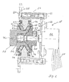
- Fig. 2 shows a section through a steering head 18 according to the invention.
- the steering head 18 has a base plate 20, on which a central bearing body 22 is integrally formed.
- the encircling bearing body 22 has on both sides each circumferential raceways for arranged in cages 23 and 25 rolling elements 24 and 26.
- the central bearing body 22 has a radially inwardly projecting tip, so that the raceways for the rolling elements 24 and 26 a make sharp angles with each other to provide an O-configuration for the formed support bearing.
- the steering shaft 28 has centrally a receptacle 32 with an internal thread into which a projecting portion of the output shaft 30 is screwed with its external thread.
- the output shaft 30 and the steering shaft 28 each have a radially outwardly facing and circumferential shoulder 34, 36.
- the shoulders 34 and 36 each have a tilt adapted to the central bearing body.
- Each of the shoulders 34, 36 has a ring 38, 40 covering the roller body.
- the rings are each sealed by a lip seal 42, 44 with respect to the stationary bearing body 22.
- a central threaded pin 46 is provided.
- the threaded pin 46 is screwed centrally into the output shaft, which in turn rests in the receptacle 32 of the steering shaft 28.
- the rotational movement of the output shaft 30 is transmitted to a sensor 52 by means of a sensor shaft 50.
- the sensor shaft 50 may be arranged, for example, by a non-circular cross-section co-rotating in the output shaft 30. Is secured, the sensor shaft 50 via a locking pin 54, which in radial Direction is screwed into the output shaft 30.
- the sensor 52 detects the rotational movement and outputs corresponding control signals via lines 58 to a connector, not shown.
- the sensor 52 is held against rotation on the base plate 20 via webs 56.
- the webs 56 are each screwed via a screw 60, 62.
- the screw 62 carries a plate 64 with the sensor 52.
- the steering shaft 28 is connected directly or indirectly to the steering wheel 14.
- a rotational movement of the steering shaft 28 is transmitted one-to-one to the output shaft 30.
- the case to be overcome resistance in the form of a steering torque is determined by the degree of screwing of the steering shaft and output shaft.
- the rotational movement of the output shaft 30 is transmitted via a sensor shaft 50 to a sensor 52, where the steering angle detected and forwarded via a connector 58 to a steering control.
Landscapes
- Engineering & Computer Science (AREA)
- Chemical & Material Sciences (AREA)
- Combustion & Propulsion (AREA)
- Transportation (AREA)
- Mechanical Engineering (AREA)
- Steering Controls (AREA)
Abstract
Description
- Die vorliegende Erfindung betrifft einen Lenkkopf für einen drehbaren Lenkwinkelgeber an einem Flurförderzeug.
- Ein Lenkkopf für einen drehbaren Lenkwinkelgeber an einem Flurförderzeug erlaubt beispielsweise ein Lenkrad oder einen sonstigen drehbaren Lenkwinkelgeber zu betätigen, um ein oder mehrere gelenkte Räder an dem Flurförderzeug in die gewünschte Richtung zu lenken. Es ist bei Flurförderzeugen bekannt, das gelenkte Rad mittels einer elektrischen Lenkung zu lenken, bei der das Lenkrad mit einer Sensorik ausgestattet ist, welche seine Lenkbewegungen an die Lenksteuerung übermittelt. Hierbei werden die Lenkbewegungen des Lenkwinkelgebers elektronisch erfasst und als elektronische Signale an eine Lenksteuerung übermittelt. Die Lenksteuerung treibt einen elektrischen Antrieb an, welcher das gelenkte Rad in seiner Winkelstellung entsprechend der Bewegung des Lenkrads bewegt.
- Aus
EP 1 330 630 B1 ist ein Wälzlager für Lenkräder bekannt, das mit einem Sensor ausgestattet ist. Der Lenkkopf besitzt hierbei ein einreihiges Kugellager, das zentral eine Lenkwelle lagert. Die Lenkwelle besitzt auf einer Stirnseite Befestigungsbohrungen zur Verbindung mit einem Lenkrad. An der gegenüberliegenden Seite besitzt der Lenkkopf Permanentmagnete, über die eine Drehbewegung von einem magnetischen Sensor erfasst werden kann. Das hierbei auftretende Lenkmoment ist sehr gering und wird im Wesentlichen von der Wellendichtung am Kugellager aufgebracht. - In der Vergangenheit wurde festgestellt, dass die Bediener einer elektrischen Lenkung an einem Flurförderzeug sehr sensitiv auf das einer Lenkbewegung des Lenkwinkelgebers entgegenwirkende Lenkmoment reagieren. Aufgrund von Bauteiltoleranzen oder Verschleiß an der Wellendichtung kann das Lenkmoment während der Lebensdauer der Lenkung schwanken und den Fahrer so initiieren.
- Der Erfindung liegt die Aufgabe zugrunde, mit möglichst einfachen Mitteln einen Lenkkopf zur Verfügung zu stellen, der ein vordefiniertes und über die Zeit konstantes Lenkmoment für eine Bedienperson schafft.
- Erfindungsgemäß wird die Aufgabe durch einen Lenkkopf mit den Merkmalen aus Anspruch 1 gelöst. Vorteilhafte Ausgestaltungen bilden den Gegenstand der Unteransprüche.
- Der erfindungsgemäße Lenkkopf ist vorgesehen und bestimmt für einen drehbaren Lenkwinkelgeber an einem Flurförderzeug. Der erfindungsgemäße Lenkkopf besitzt eine Lenkwelle, eine Ausgangswelle und eine Lagereinheit. Die Lenkwelle ist vorgesehen, um eine Verbindung mit einem lenkbaren Lenkwinkelgeber herzustellen. Die Ausgangswelle des Lenkkopfs ist vorgesehen, um eine Verbindung mit einer eine Drehbewegung erfassenden Sensorik herzustellen. Die erfindungsgemäß vorgesehene Lagereinheit besitzt zwei in O-Form zueinander angeordnete Lagerreihen, von denen eine mit der Lenkwelle und eine mit der Ausgangswelle zusammenwirkt. Lenk- und Ausgangswelle sind mit Mitteln versehen, um diese gegeneinander mit einer vordefinierten Kraft gegen die Lagerreihen zu verspannen. Durch das Verspannen entsteht das Lenkmoment in der gewünschten Größe. Dieses einer Drehbewegung entgegengesetzte Lenkmoment an dem erfindungsgemäßen Lenkkopf wird durch ein Verspannen zwischen Lenk- und Ausgangswelle erzielt und ist daher von Bauteiltoleranzen und Verschleiß unabhängig.
- In einer bevorzugten Ausgestaltung sind die Mittel an Lenk- und Ausgangswelle ein Innen- und ein Außengewinde, durch deren Verschraubung die Kraft auf die Lagereinheit mit ihren Lagerreihen einstellbar ist. Der besondere Vorteil an der Verschraubung von Lenk- und Ausgangswelle liegt darin, dass sich ein definiertes Drehmoment und damit eine definierte Vorspannung auf die Lagerreihen erzeugen lassen. Hierdurch kann das für den Lenkwinkelgeber vorgesehene Lenkmoment in einfacher Weise definiert und eingestellt werden.
- In einer bevorzugten Ausgestaltung ist die ein Außengewinde aufweisende Welle mit einer zentralen Bohrung und mit einem Gewindestift zur Anordnung in der zentralen Bohrung und einem Verspannen zwischen Ausgangswelle und Lenkwelle relativ zueinander vorgesehen. Der in der zentralen Bohrung angeordnete Gewindestift sichert die Schraubverbindung zwischen Ausgangswelle und Lenkwelle und stellt ein konstantes Lenkmoment sicher.
- In einer bevorzugten Weiterbildung besitzen Lenkwelle und Ausgangswelle jeweils eine Schulter, die jeweils eine Laufbahn für die Lagerreihe mit ihren Wälzkörpern bildet. Die Laufbahnen sind jeweils parallel zu den Laufbahnen der Lagereinheit. Durch ein Verschrauben zwischen Lenkwelle und Ausgangswelle werden die Laufbahnen in axialer Richtung aufeinander zu bewegt und erhöhen so das einer Drehbewegung entgegenstehende Moment der Lagerreihen.
- In einer bevorzugten Ausgestaltung besitzen die Schultern jeweils an ihrem Ende einen vorstehenden Ring, der sich axial nach innen über die Wälzkörper erstreckt. Der zwischen Laufbahnen gebildete Wälzspalt wird durch den nach innen vorstehenden Ring überdeckt und kann bevorzugt über eine Dichtung abgedichtet werden.
- In einer bevorzugten Weitergestaltung besitzt die Ausgangswelle eine zentrale Aufnahme für eine Sensorwelle, die mit einer Sensorik verbunden ist. Die Sensorwelle nimmt die Drehbewegung der Ausgangswelle auf und leitet diese an die Sensorik weiter, von wo aus dann eine entsprechende Ansteuerung des oder der gelenkten Räder erfolgt.
- In einer bevorzugten Ausgestaltung besitzt die Ausgangswelle eine mit einem Innengewinde versehene Querbohrung zur Aufnahme eines Gewindestifts. Der in die Ausgangswelle eingesetzte Gewindestift sichert eine Verbindung mit der Sensorwelle, damit die Sensorik auch bei Erschütterungen nicht die Verbindung verliert.
- In einer bevorzugten Ausgestaltung besitzt die Lagereinheit einen zentralen Lagerkörper mit zwei Laufbahnen. Die Laufbahnen sind gegeneinander verwinkelt, so dass die normalen Richtungen auf der Laufbahn voneinander fortweist, um eine O-Anordnung des Lagers zu bilden.
- In einer bevorzugten Ausgestaltung ist der zentrale Lagerkörper mit seinen beiden Laufbahnen einstückig ausgebildet.
- Ein bevorzugtes Ausführungsbeispiel des erfindungsgemäßen Lenkkopfs wird nachfolgend näher erläutert. Es zeigen:
- Fig. 1
- in einer schematischen Ansicht ein Flurförderzeug mit einer elektrischen Lenkung und
- Fig.2
- einen schematischen Querschnitt durch den erfindungsgemäßen Lenkkopf.
-
Fig. 1 zeigt einen Schubmaststapler 10 mit einer Fahrerkabine 12, in der ein Lenkrad 14 angeordnet ist. Über das Lenkrad 14 wird das gelenkte und angetriebene Rad 16 ausgerichtet. Das dargestellte Flurförderzeug ist mit einer elektrischen Lenkung ausgestattet. Bei einer elektrischen Lenkung wird eine Drehbewegung des Lenkrades 14 elektrisch abgegriffen und als eine entsprechende Sollwertvorgabe an eine Lenksteuerung elektrisch übertragen. Die Lenksteuerung ermittelt, beispielsweise abhängig von der Ist-Stellung des oder der gelenkten Räder 16, ein Signal zur Ansteuerung des Rades 16. - Bei der elektrischen Lenkung fehlt an dem Lenkrad eine mechanische Rückmeldung über die Bewegung des gelenkten Rades. Unabhängig von der Bewegung des gelenkten Rades wird an dem Lenkkopf einer elektrischen Lenkung ein Lenkmoment erzeugt. Das Lenkmoment ist das einer Drehung des Lenkrades oder des Lenkwinkelgebers entgegenwirkende Moment. Das Lenkmoment stellt beispielsweise sicher, dass ein mit einem Knauf versehenes Lenkrad in seiner Position verbleibt und sich nicht stets in eine Position dreht, in der der Lenkknauf nach unten zeigt. Hinzu kommt, dass das Lenkmoment von einem Fahrer sehr genau wahrgenommen wird, beispielsweise wenn das Flurförderzeug mit sehr feinen Lenkbewegungen genau angesteuert wird.
-
Fig. 2 zeigt einen Schnitt durch einen erfindungsgemäßen Lenkkopf 18. Der Lenkkopf 18 besitzt eine Grundplatte 20, an der ein zentraler Lagerkörper 22 einstückig ausgebildet ist. Der umlaufende Lagerkörper 22 besitzt auf seinen beiden Seiten jeweils umlaufende Laufbahnen für in Käfigen 23 und 25 angeordnete Wälzkörper 24 und 26. Der zentrale Lagerkörper 22 besitzt eine radial nach innen vorstehende Spitze, so dass die Laufbahnen für die Wälzkörper 24 und 26 einen spitzen Winkel miteinander einschließen und so eine O-Konfiguration für das gebildete Stützlager bereitstellen. - An dem zentralen Lagerkörper 22 gelagert sind eine Lenkwelle 28 und eine Ausgangswelle 30. Die Lenkwelle 28 besitzt zentral eine Aufnahme 32 mit einem Innengewinde, in das ein vorstehender Abschnitt der Ausgangswelle 30 mit seinem Außengewinde eingeschraubt ist. Ausgangswelle 30 und Lenkwelle 28 besitzen jeweils eine radial nach außen weisende und umlaufende Schulter 34, 36. Die Schultern 34 und 36 besitzen jeweils eine an den zentralen Lagerkörper angepasste Neigung. Durch ein Verschrauben von Ausgangswelle 30 und Lenkwelle 28 gegeneinander, wird der Abstand zwischen den Schultern 34 und 36 verringert, so dass die Kraft auf die Wälzkörper 24 und 26 vergrößert wird. Hierdurch entsteht ein durch die Verschraubung einstellbares Lenkmoment, das im Wesentlichen durch die Kraft auf die Wälzkörper 24 und 26 bestimmt ist.
- Jede der Schultern 34, 36 besitzt einen den Wälzkörper überdeckenden Ring 38, 40. Die Ringe sind jeweils über eine Lippendichtung 42, 44 gegenüber dem feststehenden Lagerkörper 22 abgedichtet.
- Um die Schraubverbindung zwischen Lenkwelle 28 und Ausgangswelle 30 zu sichern, ist ein zentraler Gewindestift 46 vorgesehen. Der Gewindestift 46 ist zentral in die Ausgangswelle geschraubt, die wiederum in der Aufnahme 32 der Lenkwelle 28 anliegt.
- Die Drehbewegung der Ausgangswelle 30 wird mit Hilfe einer Sensorwelle 50 auf einen Sensor 52 übertragen. Die Sensorwelle 50 kann beispielsweise durch einen nicht runden Querschnitt mitdrehend in der Ausgangswelle 30 angeordnet sein. Gesichert wird die Sensorwelle 50 über einen Sicherungsstift 54, der in radialer Richtung in die Ausgangswelle 30 eingeschraubt ist. Die Sensorik 52 erfasst die Drehbewegung und gibt entsprechende Steuersignale über Leitungen 58 an einen nicht mehr dargestellten Steckverbinder aus.
- Die Sensorik 52 ist verdrehsicher an der Grundplatte 20 über Stege 56 gehalten. Die Stege 56 sind jeweils über eine Schraube 60, 62 verschraubt. Die Schraube 62 trägt eine Platte 64 mit der Sensorik 52.
- Im Gebrauch des erfindungsgemäßen Lenkkopfs 18 ist die Lenkwelle 28 direkt oder indirekt mit dem Lenkrad 14 verbunden. Eine Drehbewegung der Lenkwelle 28 wird eins zu eins auf die Ausgangswelle 30 übertragen. Der hierbei zu überwindende Widerstand in Form eines Lenkmoments ist durch den Grad der Verschraubung von Lenkwelle und Ausgangswelle festgelegt. Die Drehbewegung der Ausgangswelle 30 wird über eine Sensorwelle 50 an eine Sensorik 52 übertragen, wo der Lenkwinkel erfasst und über einen Steckverbinder 58 an eine Lenksteuerung weitergeleitet.
-
- 10
- Schubmaststapler
- 12
- Fahrerkabine
- 14
- Lenkrad
- 16
- Rad
- 18
- Lenkkopf
- 20
- Grundplatte
- 22
- Lagerkörper
- 23
- Käfig
- 24
- Wälzkörper
- 25
- Käfig
- 26
- Wälzkörper
- 28
- Lenkwelle
- 30
- Ausgangswelle
- 32
- Aufnahme
- 34
- Schulter
- 36
- Schulter
- 38
- Ring
- 40
- Ring
- 42
- Lippendichtung
- 44
- Lippendichtung
- 46
- Gewindestift
- 50
- Sensorwelle
- 52
- Sensor
- 54
- Sicherungsstift
- 56
- Stege
- 58
- Leitungen
- 60
- Schraube
- 62
- Schraube
- 64
- Platte
Claims (10)
- Lenkkopf (18) für einen drehbaren Lenkwinkelgeber an einem Flurförderzeug (10) mit- einer Lenkwelle (28), die zur Verbindung mit dem Lenkwinkelgeber vorgesehen ist,- einer Ausgangswelle (30), die zu einer Verbindung mit einer eine Drehbewegung erfassenden Sensorik (52) vorgesehen ist, und- einer Lagereinheit (22, 24, 26), die zwei in O-Form zueinander angeordnete Lagerreihen aufweist, von denen eine mit der Lenkwelle (28) und eine mit der Ausgangswelle (30) zusammenwirkt,- wobei Mittel an Lenk- und Ausgangswelle vorgesehen sind, um Lenk- und Ausgangswelle gegeneinander mit einer vordefinierten Kraft gegen die Lagereinheit zu verspannen.
- Lenkkopf nach Anspruch 1, dadurch gekennzeichnet, dass die Mittel an Lenk- und Ausgangswelle (28, 30) ein Innen- und ein Außengewinde aufweisen, durch deren Verschraubung die Kraft auf die Lagereinheit einstellbar ist.
- Lenkkopf nach Anspruch 2, dadurch gekennzeichnet, dass die ein Außengewinde aufweisende Welle eine zentrale Bohrung mit einem Innengewindestift zum Verspannen von Ausgangswelle und Lenkwelle relativ zueinander besitzt.
- Lenkkopf nach einem der Ansprüche 1 bis 3, dadurch gekennzeichnet, dass Lenk- und Ausgangswelle jeweils eine Schulter aufweisen, die eine Laufbahn für die Lagereinheit bildet.
- Lenkkopf nach einem der Ansprüche 1 bis 4, dadurch gekennzeichnet, dass die Schultern jeweils an ihrem Ende einen vorstehenden Ring besitzen, der sich axial nach innen über die Wälzkörper erstreckt.
- Lenkkopf nach Anspruch 5, dadurch gekennzeichnet, dass radial außenliegend eine Dichtung auf dem Ring angeordnet ist.
- Lenkkopf nach einem der Ansprüche 1 bis 6, dadurch gekennzeichnet, dass die Ausgangswelle eine zentrale Aufnahme für eine Sensorwelle (50) der Sensorik (52) aufweist.
- Lenkkopf nach Anspruch 7, dadurch gekennzeichnet, dass die Ausgangswelle eine mit Innengewinde versehene Querbohrung zur Aufnahme eines Gewindestifts aufweist.
- Lenkkopf nach einem der Ansprüche 1 bis 8, dadurch gekennzeichnet, dass die Lagereinheit einen zentralen Lagerkörper mit zwei Laufbahnen besitzt.
- Lenkkopf nach Anspruch 9, dadurch gekennzeichnet, dass der zentrale Lagerkörper einstückig ausgebildet ist.
Priority Applications (1)
| Application Number | Priority Date | Filing Date | Title |
|---|---|---|---|
| EP15188768.4A EP3153381B1 (de) | 2015-10-07 | 2015-10-07 | Lenkkopf für einen drehbaren lenkwinkelgeber |
Applications Claiming Priority (1)
| Application Number | Priority Date | Filing Date | Title |
|---|---|---|---|
| EP15188768.4A EP3153381B1 (de) | 2015-10-07 | 2015-10-07 | Lenkkopf für einen drehbaren lenkwinkelgeber |
Publications (2)
| Publication Number | Publication Date |
|---|---|
| EP3153381A1 true EP3153381A1 (de) | 2017-04-12 |
| EP3153381B1 EP3153381B1 (de) | 2018-03-14 |
Family
ID=54291122
Family Applications (1)
| Application Number | Title | Priority Date | Filing Date |
|---|---|---|---|
| EP15188768.4A Active EP3153381B1 (de) | 2015-10-07 | 2015-10-07 | Lenkkopf für einen drehbaren lenkwinkelgeber |
Country Status (1)
| Country | Link |
|---|---|
| EP (1) | EP3153381B1 (de) |
Citations (4)
| Publication number | Priority date | Publication date | Assignee | Title |
|---|---|---|---|---|
| JPS598564A (ja) * | 1982-07-08 | 1984-01-17 | Nissan Motor Co Ltd | 車両の舵角検出装置 |
| US4988219A (en) * | 1988-01-28 | 1991-01-29 | The Torrington Company | Roller bearing assembly with sensor device |
| JPH09304048A (ja) * | 1996-05-16 | 1997-11-28 | Tokyo Seimitsu Co Ltd | 角度検出装置及びハンドル回転角度検出装置 |
| EP1330630B1 (de) | 2000-11-02 | 2010-06-09 | Aktiebolaget SKF | Mit sensor ausgestattetes wälzlager für lenkräder |
-
2015
- 2015-10-07 EP EP15188768.4A patent/EP3153381B1/de active Active
Patent Citations (4)
| Publication number | Priority date | Publication date | Assignee | Title |
|---|---|---|---|---|
| JPS598564A (ja) * | 1982-07-08 | 1984-01-17 | Nissan Motor Co Ltd | 車両の舵角検出装置 |
| US4988219A (en) * | 1988-01-28 | 1991-01-29 | The Torrington Company | Roller bearing assembly with sensor device |
| JPH09304048A (ja) * | 1996-05-16 | 1997-11-28 | Tokyo Seimitsu Co Ltd | 角度検出装置及びハンドル回転角度検出装置 |
| EP1330630B1 (de) | 2000-11-02 | 2010-06-09 | Aktiebolaget SKF | Mit sensor ausgestattetes wälzlager für lenkräder |
Also Published As
| Publication number | Publication date |
|---|---|
| EP3153381B1 (de) | 2018-03-14 |
Similar Documents
| Publication | Publication Date | Title |
|---|---|---|
| DE102013019726B4 (de) | Fahrzeug, insbesondere AGV oder FTS | |
| DE102016211694B3 (de) | Getriebeeinheit für ein Kraftfahrzeug | |
| EP3172072B1 (de) | Radträger für ein zweispuriges kraftfahrzeug | |
| DE102014202948B4 (de) | Wälzgenietete Radlageranordnung mit gestuftem Innenring | |
| EP1463660A1 (de) | Elektrisch unterstützte hilfskraftlenkung für kraftfahrzeuge | |
| EP2576244A1 (de) | Elektrischer radantrieb | |
| DE102010054696B4 (de) | Deichselgeführtes Flurförderzeug mit einer elektrischen Lenkung | |
| EP2726749B1 (de) | Kompakte axial-radial-lagerung | |
| DE10338959B4 (de) | Anordnung eines Sensors an einer Radlagereinheit | |
| EP1958800A2 (de) | Elektromechanische Stellvorrichtung für Radaufhängungen von Kraftfahrzeugen | |
| DE102016112234A1 (de) | Haltevorrichtung für eine exzentrische justierungsvorrichtung | |
| EP1925830A1 (de) | Wälzlager | |
| EP1638833A1 (de) | Einrichtung zur erfassung einer drehbewegung in einer fahrzeug-lenkeinrichtung | |
| WO2003095853A1 (de) | Wälzlager zur lagerung einer lenkwelle | |
| EP2117906B1 (de) | Elektromechanische lenkung | |
| EP3153381B1 (de) | Lenkkopf für einen drehbaren lenkwinkelgeber | |
| DE102008049041B4 (de) | Lageranordnung | |
| WO2014032834A1 (de) | Radlageranordnung umfassend eine bremsscheibe mit radzentrierung | |
| DE60300772T2 (de) | Kompaktes Wälzlager mit Bremseinrichtung | |
| EP2015952B1 (de) | Antrieb für ein flurförderzeug | |
| DE60213586T2 (de) | Lenkbare radaufhängung | |
| DE102023103513A1 (de) | Drehwinkelbegrenzungseinrichtung für Lenkeinheit und Lenkeinheit | |
| WO2010023201A1 (de) | Lenkwinkelsensor mit oldham kupplung | |
| WO2003076832A1 (de) | Wälzkörpergewindetrieb | |
| DE202016103794U1 (de) | Getriebeeinheit für ein Kraftfahrzeug |
Legal Events
| Date | Code | Title | Description |
|---|---|---|---|
| PUAI | Public reference made under article 153(3) epc to a published international application that has entered the european phase |
Free format text: ORIGINAL CODE: 0009012 |
|
| STAA | Information on the status of an ep patent application or granted ep patent |
Free format text: STATUS: THE APPLICATION HAS BEEN PUBLISHED |
|
| AK | Designated contracting states |
Kind code of ref document: A1 Designated state(s): AL AT BE BG CH CY CZ DE DK EE ES FI FR GB GR HR HU IE IS IT LI LT LU LV MC MK MT NL NO PL PT RO RS SE SI SK SM TR |
|
| AX | Request for extension of the european patent |
Extension state: BA ME |
|
| STAA | Information on the status of an ep patent application or granted ep patent |
Free format text: STATUS: REQUEST FOR EXAMINATION WAS MADE |
|
| 17P | Request for examination filed |
Effective date: 20171010 |
|
| RBV | Designated contracting states (corrected) |
Designated state(s): AL AT BE BG CH CY CZ DE DK EE ES FI FR GB GR HR HU IE IS IT LI LT LU LV MC MK MT NL NO PL PT RO RS SE SI SK SM TR |
|
| GRAP | Despatch of communication of intention to grant a patent |
Free format text: ORIGINAL CODE: EPIDOSNIGR1 |
|
| STAA | Information on the status of an ep patent application or granted ep patent |
Free format text: STATUS: GRANT OF PATENT IS INTENDED |
|
| INTG | Intention to grant announced |
Effective date: 20171204 |
|
| GRAS | Grant fee paid |
Free format text: ORIGINAL CODE: EPIDOSNIGR3 |
|
| GRAA | (expected) grant |
Free format text: ORIGINAL CODE: 0009210 |
|
| STAA | Information on the status of an ep patent application or granted ep patent |
Free format text: STATUS: THE PATENT HAS BEEN GRANTED |
|
| RAP1 | Party data changed (applicant data changed or rights of an application transferred) |
Owner name: JUNGHEINRICH AKTIENGESELLSCHAFT |
|
| AK | Designated contracting states |
Kind code of ref document: B1 Designated state(s): AL AT BE BG CH CY CZ DE DK EE ES FI FR GB GR HR HU IE IS IT LI LT LU LV MC MK MT NL NO PL PT RO RS SE SI SK SM TR |
|
| REG | Reference to a national code |
Ref country code: GB Ref legal event code: FG4D Free format text: NOT ENGLISH |
|
| REG | Reference to a national code |
Ref country code: CH Ref legal event code: EP Ref country code: AT Ref legal event code: REF Ref document number: 978588 Country of ref document: AT Kind code of ref document: T Effective date: 20180315 |
|
| REG | Reference to a national code |
Ref country code: IE Ref legal event code: FG4D Free format text: LANGUAGE OF EP DOCUMENT: GERMAN |
|
| REG | Reference to a national code |
Ref country code: DE Ref legal event code: R096 Ref document number: 502015003365 Country of ref document: DE |
|
| REG | Reference to a national code |
Ref country code: SE Ref legal event code: TRGR |
|
| REG | Reference to a national code |
Ref country code: NL Ref legal event code: MP Effective date: 20180314 |
|
| REG | Reference to a national code |
Ref country code: LT Ref legal event code: MG4D |
|
| PG25 | Lapsed in a contracting state [announced via postgrant information from national office to epo] |
Ref country code: HR Free format text: LAPSE BECAUSE OF FAILURE TO SUBMIT A TRANSLATION OF THE DESCRIPTION OR TO PAY THE FEE WITHIN THE PRESCRIBED TIME-LIMIT Effective date: 20180314 Ref country code: FI Free format text: LAPSE BECAUSE OF FAILURE TO SUBMIT A TRANSLATION OF THE DESCRIPTION OR TO PAY THE FEE WITHIN THE PRESCRIBED TIME-LIMIT Effective date: 20180314 Ref country code: NO Free format text: LAPSE BECAUSE OF FAILURE TO SUBMIT A TRANSLATION OF THE DESCRIPTION OR TO PAY THE FEE WITHIN THE PRESCRIBED TIME-LIMIT Effective date: 20180614 Ref country code: CY Free format text: LAPSE BECAUSE OF FAILURE TO SUBMIT A TRANSLATION OF THE DESCRIPTION OR TO PAY THE FEE WITHIN THE PRESCRIBED TIME-LIMIT Effective date: 20180314 Ref country code: LT Free format text: LAPSE BECAUSE OF FAILURE TO SUBMIT A TRANSLATION OF THE DESCRIPTION OR TO PAY THE FEE WITHIN THE PRESCRIBED TIME-LIMIT Effective date: 20180314 |
|
| PG25 | Lapsed in a contracting state [announced via postgrant information from national office to epo] |
Ref country code: LV Free format text: LAPSE BECAUSE OF FAILURE TO SUBMIT A TRANSLATION OF THE DESCRIPTION OR TO PAY THE FEE WITHIN THE PRESCRIBED TIME-LIMIT Effective date: 20180314 Ref country code: RS Free format text: LAPSE BECAUSE OF FAILURE TO SUBMIT A TRANSLATION OF THE DESCRIPTION OR TO PAY THE FEE WITHIN THE PRESCRIBED TIME-LIMIT Effective date: 20180314 Ref country code: BG Free format text: LAPSE BECAUSE OF FAILURE TO SUBMIT A TRANSLATION OF THE DESCRIPTION OR TO PAY THE FEE WITHIN THE PRESCRIBED TIME-LIMIT Effective date: 20180614 Ref country code: GR Free format text: LAPSE BECAUSE OF FAILURE TO SUBMIT A TRANSLATION OF THE DESCRIPTION OR TO PAY THE FEE WITHIN THE PRESCRIBED TIME-LIMIT Effective date: 20180615 |
|
| PG25 | Lapsed in a contracting state [announced via postgrant information from national office to epo] |
Ref country code: MT Free format text: LAPSE BECAUSE OF FAILURE TO SUBMIT A TRANSLATION OF THE DESCRIPTION OR TO PAY THE FEE WITHIN THE PRESCRIBED TIME-LIMIT Effective date: 20180314 |
|
| PG25 | Lapsed in a contracting state [announced via postgrant information from national office to epo] |
Ref country code: RO Free format text: LAPSE BECAUSE OF FAILURE TO SUBMIT A TRANSLATION OF THE DESCRIPTION OR TO PAY THE FEE WITHIN THE PRESCRIBED TIME-LIMIT Effective date: 20180314 Ref country code: EE Free format text: LAPSE BECAUSE OF FAILURE TO SUBMIT A TRANSLATION OF THE DESCRIPTION OR TO PAY THE FEE WITHIN THE PRESCRIBED TIME-LIMIT Effective date: 20180314 Ref country code: NL Free format text: LAPSE BECAUSE OF FAILURE TO SUBMIT A TRANSLATION OF THE DESCRIPTION OR TO PAY THE FEE WITHIN THE PRESCRIBED TIME-LIMIT Effective date: 20180314 Ref country code: AL Free format text: LAPSE BECAUSE OF FAILURE TO SUBMIT A TRANSLATION OF THE DESCRIPTION OR TO PAY THE FEE WITHIN THE PRESCRIBED TIME-LIMIT Effective date: 20180314 Ref country code: ES Free format text: LAPSE BECAUSE OF FAILURE TO SUBMIT A TRANSLATION OF THE DESCRIPTION OR TO PAY THE FEE WITHIN THE PRESCRIBED TIME-LIMIT Effective date: 20180314 Ref country code: PL Free format text: LAPSE BECAUSE OF FAILURE TO SUBMIT A TRANSLATION OF THE DESCRIPTION OR TO PAY THE FEE WITHIN THE PRESCRIBED TIME-LIMIT Effective date: 20180314 |
|
| PG25 | Lapsed in a contracting state [announced via postgrant information from national office to epo] |
Ref country code: SK Free format text: LAPSE BECAUSE OF FAILURE TO SUBMIT A TRANSLATION OF THE DESCRIPTION OR TO PAY THE FEE WITHIN THE PRESCRIBED TIME-LIMIT Effective date: 20180314 Ref country code: CZ Free format text: LAPSE BECAUSE OF FAILURE TO SUBMIT A TRANSLATION OF THE DESCRIPTION OR TO PAY THE FEE WITHIN THE PRESCRIBED TIME-LIMIT Effective date: 20180314 Ref country code: SM Free format text: LAPSE BECAUSE OF FAILURE TO SUBMIT A TRANSLATION OF THE DESCRIPTION OR TO PAY THE FEE WITHIN THE PRESCRIBED TIME-LIMIT Effective date: 20180314 |
|
| REG | Reference to a national code |
Ref country code: DE Ref legal event code: R097 Ref document number: 502015003365 Country of ref document: DE |
|
| PG25 | Lapsed in a contracting state [announced via postgrant information from national office to epo] |
Ref country code: PT Free format text: LAPSE BECAUSE OF FAILURE TO SUBMIT A TRANSLATION OF THE DESCRIPTION OR TO PAY THE FEE WITHIN THE PRESCRIBED TIME-LIMIT Effective date: 20180716 |
|
| PLBE | No opposition filed within time limit |
Free format text: ORIGINAL CODE: 0009261 |
|
| STAA | Information on the status of an ep patent application or granted ep patent |
Free format text: STATUS: NO OPPOSITION FILED WITHIN TIME LIMIT |
|
| PG25 | Lapsed in a contracting state [announced via postgrant information from national office to epo] |
Ref country code: DK Free format text: LAPSE BECAUSE OF FAILURE TO SUBMIT A TRANSLATION OF THE DESCRIPTION OR TO PAY THE FEE WITHIN THE PRESCRIBED TIME-LIMIT Effective date: 20180314 |
|
| 26N | No opposition filed |
Effective date: 20181217 |
|
| REG | Reference to a national code |
Ref country code: CH Ref legal event code: PL |
|
| REG | Reference to a national code |
Ref country code: BE Ref legal event code: MM Effective date: 20181031 |
|
| PG25 | Lapsed in a contracting state [announced via postgrant information from national office to epo] |
Ref country code: MC Free format text: LAPSE BECAUSE OF FAILURE TO SUBMIT A TRANSLATION OF THE DESCRIPTION OR TO PAY THE FEE WITHIN THE PRESCRIBED TIME-LIMIT Effective date: 20180314 Ref country code: LU Free format text: LAPSE BECAUSE OF NON-PAYMENT OF DUE FEES Effective date: 20181007 |
|
| REG | Reference to a national code |
Ref country code: IE Ref legal event code: MM4A |
|
| PG25 | Lapsed in a contracting state [announced via postgrant information from national office to epo] |
Ref country code: LI Free format text: LAPSE BECAUSE OF NON-PAYMENT OF DUE FEES Effective date: 20181031 Ref country code: BE Free format text: LAPSE BECAUSE OF NON-PAYMENT OF DUE FEES Effective date: 20181031 Ref country code: CH Free format text: LAPSE BECAUSE OF NON-PAYMENT OF DUE FEES Effective date: 20181031 |
|
| PG25 | Lapsed in a contracting state [announced via postgrant information from national office to epo] |
Ref country code: IE Free format text: LAPSE BECAUSE OF NON-PAYMENT OF DUE FEES Effective date: 20181007 |
|
| PG25 | Lapsed in a contracting state [announced via postgrant information from national office to epo] |
Ref country code: TR Free format text: LAPSE BECAUSE OF FAILURE TO SUBMIT A TRANSLATION OF THE DESCRIPTION OR TO PAY THE FEE WITHIN THE PRESCRIBED TIME-LIMIT Effective date: 20180314 |
|
| PG25 | Lapsed in a contracting state [announced via postgrant information from national office to epo] |
Ref country code: MK Free format text: LAPSE BECAUSE OF NON-PAYMENT OF DUE FEES Effective date: 20180314 Ref country code: HU Free format text: LAPSE BECAUSE OF FAILURE TO SUBMIT A TRANSLATION OF THE DESCRIPTION OR TO PAY THE FEE WITHIN THE PRESCRIBED TIME-LIMIT; INVALID AB INITIO Effective date: 20151007 |
|
| PG25 | Lapsed in a contracting state [announced via postgrant information from national office to epo] |
Ref country code: IS Free format text: LAPSE BECAUSE OF FAILURE TO SUBMIT A TRANSLATION OF THE DESCRIPTION OR TO PAY THE FEE WITHIN THE PRESCRIBED TIME-LIMIT Effective date: 20180714 |
|
| PG25 | Lapsed in a contracting state [announced via postgrant information from national office to epo] |
Ref country code: SI Free format text: LAPSE BECAUSE OF NON-PAYMENT OF DUE FEES Effective date: 20181007 |
|
| REG | Reference to a national code |
Ref country code: AT Ref legal event code: MM01 Ref document number: 978588 Country of ref document: AT Kind code of ref document: T Effective date: 20201007 |
|
| PG25 | Lapsed in a contracting state [announced via postgrant information from national office to epo] |
Ref country code: AT Free format text: LAPSE BECAUSE OF NON-PAYMENT OF DUE FEES Effective date: 20201007 |
|
| PGFP | Annual fee paid to national office [announced via postgrant information from national office to epo] |
Ref country code: DE Payment date: 20251020 Year of fee payment: 11 |
|
| PGFP | Annual fee paid to national office [announced via postgrant information from national office to epo] |
Ref country code: GB Payment date: 20251024 Year of fee payment: 11 |
|
| PGFP | Annual fee paid to national office [announced via postgrant information from national office to epo] |
Ref country code: IT Payment date: 20251031 Year of fee payment: 11 |
|
| PGFP | Annual fee paid to national office [announced via postgrant information from national office to epo] |
Ref country code: FR Payment date: 20251027 Year of fee payment: 11 |
|
| PGFP | Annual fee paid to national office [announced via postgrant information from national office to epo] |
Ref country code: SE Payment date: 20251023 Year of fee payment: 11 |