EP3153223A1 - Adsorptive gastrennung mit einer wärmeleitenden struktur - Google Patents
Adsorptive gastrennung mit einer wärmeleitenden struktur Download PDFInfo
- Publication number
- EP3153223A1 EP3153223A1 EP16198431.5A EP16198431A EP3153223A1 EP 3153223 A1 EP3153223 A1 EP 3153223A1 EP 16198431 A EP16198431 A EP 16198431A EP 3153223 A1 EP3153223 A1 EP 3153223A1
- Authority
- EP
- European Patent Office
- Prior art keywords
- fluid
- adsorbent material
- adsorbent
- contactor
- thermally conductive
- Prior art date
- Legal status (The legal status is an assumption and is not a legal conclusion. Google has not performed a legal analysis and makes no representation as to the accuracy of the status listed.)
- Withdrawn
Links
Images


Classifications
-
- B—PERFORMING OPERATIONS; TRANSPORTING
- B01—PHYSICAL OR CHEMICAL PROCESSES OR APPARATUS IN GENERAL
- B01D—SEPARATION
- B01D53/00—Separation of gases or vapours; Recovering vapours of volatile solvents from gases; Chemical or biological purification of waste gases, e.g. engine exhaust gases, smoke, fumes, flue gases, aerosols
- B01D53/02—Separation of gases or vapours; Recovering vapours of volatile solvents from gases; Chemical or biological purification of waste gases, e.g. engine exhaust gases, smoke, fumes, flue gases, aerosols by adsorption, e.g. preparative gas chromatography
- B01D53/04—Separation of gases or vapours; Recovering vapours of volatile solvents from gases; Chemical or biological purification of waste gases, e.g. engine exhaust gases, smoke, fumes, flue gases, aerosols by adsorption, e.g. preparative gas chromatography with stationary adsorbents
- B01D53/0462—Temperature swing adsorption
-
- C—CHEMISTRY; METALLURGY
- C10—PETROLEUM, GAS OR COKE INDUSTRIES; TECHNICAL GASES CONTAINING CARBON MONOXIDE; FUELS; LUBRICANTS; PEAT
- C10L—FUELS NOT OTHERWISE PROVIDED FOR; NATURAL GAS; SYNTHETIC NATURAL GAS OBTAINED BY PROCESSES NOT COVERED BY SUBCLASSES C10G, C10K; LIQUEFIED PETROLEUM GAS; ADDING MATERIALS TO FUELS OR FIRES TO REDUCE SMOKE OR UNDESIRABLE DEPOSITS OR TO FACILITATE SOOT REMOVAL; FIRELIGHTERS
- C10L3/00—Gaseous fuels; Natural gas; Synthetic natural gas obtained by processes not covered by subclass C10G, C10K; Liquefied petroleum gas
- C10L3/06—Natural gas; Synthetic natural gas obtained by processes not covered by C10G, C10K3/02 or C10K3/04
- C10L3/10—Working-up natural gas or synthetic natural gas
- C10L3/101—Removal of contaminants
- C10L3/102—Removal of contaminants of acid contaminants
-
- B—PERFORMING OPERATIONS; TRANSPORTING
- B01—PHYSICAL OR CHEMICAL PROCESSES OR APPARATUS IN GENERAL
- B01D—SEPARATION
- B01D2253/00—Adsorbents used in seperation treatment of gases and vapours
- B01D2253/10—Inorganic adsorbents
- B01D2253/102—Carbon
-
- B—PERFORMING OPERATIONS; TRANSPORTING
- B01—PHYSICAL OR CHEMICAL PROCESSES OR APPARATUS IN GENERAL
- B01D—SEPARATION
- B01D2253/00—Adsorbents used in seperation treatment of gases and vapours
- B01D2253/10—Inorganic adsorbents
- B01D2253/104—Alumina
-
- B—PERFORMING OPERATIONS; TRANSPORTING
- B01—PHYSICAL OR CHEMICAL PROCESSES OR APPARATUS IN GENERAL
- B01D—SEPARATION
- B01D2253/00—Adsorbents used in seperation treatment of gases and vapours
- B01D2253/10—Inorganic adsorbents
- B01D2253/106—Silica or silicates
- B01D2253/108—Zeolites
-
- B—PERFORMING OPERATIONS; TRANSPORTING
- B01—PHYSICAL OR CHEMICAL PROCESSES OR APPARATUS IN GENERAL
- B01D—SEPARATION
- B01D2253/00—Adsorbents used in seperation treatment of gases and vapours
- B01D2253/10—Inorganic adsorbents
- B01D2253/106—Silica or silicates
- B01D2253/108—Zeolites
- B01D2253/1085—Zeolites characterized by a silicon-aluminium ratio
-
- B—PERFORMING OPERATIONS; TRANSPORTING
- B01—PHYSICAL OR CHEMICAL PROCESSES OR APPARATUS IN GENERAL
- B01D—SEPARATION
- B01D2253/00—Adsorbents used in seperation treatment of gases and vapours
- B01D2253/10—Inorganic adsorbents
- B01D2253/116—Molecular sieves other than zeolites
-
- B—PERFORMING OPERATIONS; TRANSPORTING
- B01—PHYSICAL OR CHEMICAL PROCESSES OR APPARATUS IN GENERAL
- B01D—SEPARATION
- B01D2253/00—Adsorbents used in seperation treatment of gases and vapours
- B01D2253/20—Organic adsorbents
- B01D2253/202—Polymeric adsorbents
-
- B—PERFORMING OPERATIONS; TRANSPORTING
- B01—PHYSICAL OR CHEMICAL PROCESSES OR APPARATUS IN GENERAL
- B01D—SEPARATION
- B01D2253/00—Adsorbents used in seperation treatment of gases and vapours
- B01D2253/20—Organic adsorbents
- B01D2253/204—Metal organic frameworks (MOF's)
-
- B—PERFORMING OPERATIONS; TRANSPORTING
- B01—PHYSICAL OR CHEMICAL PROCESSES OR APPARATUS IN GENERAL
- B01D—SEPARATION
- B01D2253/00—Adsorbents used in seperation treatment of gases and vapours
- B01D2253/30—Physical properties of adsorbents
- B01D2253/34—Specific shapes
- B01D2253/342—Monoliths
- B01D2253/3425—Honeycomb shape
-
- B—PERFORMING OPERATIONS; TRANSPORTING
- B01—PHYSICAL OR CHEMICAL PROCESSES OR APPARATUS IN GENERAL
- B01D—SEPARATION
- B01D2256/00—Main component in the product gas stream after treatment
- B01D2256/24—Hydrocarbons
- B01D2256/245—Methane
-
- B—PERFORMING OPERATIONS; TRANSPORTING
- B01—PHYSICAL OR CHEMICAL PROCESSES OR APPARATUS IN GENERAL
- B01D—SEPARATION
- B01D2257/00—Components to be removed
- B01D2257/30—Sulfur compounds
- B01D2257/302—Sulfur oxides
-
- B—PERFORMING OPERATIONS; TRANSPORTING
- B01—PHYSICAL OR CHEMICAL PROCESSES OR APPARATUS IN GENERAL
- B01D—SEPARATION
- B01D2257/00—Components to be removed
- B01D2257/30—Sulfur compounds
- B01D2257/304—Hydrogen sulfide
-
- B—PERFORMING OPERATIONS; TRANSPORTING
- B01—PHYSICAL OR CHEMICAL PROCESSES OR APPARATUS IN GENERAL
- B01D—SEPARATION
- B01D2257/00—Components to be removed
- B01D2257/40—Nitrogen compounds
-
- B—PERFORMING OPERATIONS; TRANSPORTING
- B01—PHYSICAL OR CHEMICAL PROCESSES OR APPARATUS IN GENERAL
- B01D—SEPARATION
- B01D2257/00—Components to be removed
- B01D2257/50—Carbon oxides
- B01D2257/504—Carbon dioxide
-
- B—PERFORMING OPERATIONS; TRANSPORTING
- B01—PHYSICAL OR CHEMICAL PROCESSES OR APPARATUS IN GENERAL
- B01D—SEPARATION
- B01D2257/00—Components to be removed
- B01D2257/60—Heavy metals or heavy metal compounds
-
- B—PERFORMING OPERATIONS; TRANSPORTING
- B01—PHYSICAL OR CHEMICAL PROCESSES OR APPARATUS IN GENERAL
- B01D—SEPARATION
- B01D2257/00—Components to be removed
- B01D2257/80—Water
-
- B—PERFORMING OPERATIONS; TRANSPORTING
- B01—PHYSICAL OR CHEMICAL PROCESSES OR APPARATUS IN GENERAL
- B01D—SEPARATION
- B01D2258/00—Sources of waste gases
- B01D2258/02—Other waste gases
- B01D2258/0283—Flue gases
-
- Y—GENERAL TAGGING OF NEW TECHNOLOGICAL DEVELOPMENTS; GENERAL TAGGING OF CROSS-SECTIONAL TECHNOLOGIES SPANNING OVER SEVERAL SECTIONS OF THE IPC; TECHNICAL SUBJECTS COVERED BY FORMER USPC CROSS-REFERENCE ART COLLECTIONS [XRACs] AND DIGESTS
- Y02—TECHNOLOGIES OR APPLICATIONS FOR MITIGATION OR ADAPTATION AGAINST CLIMATE CHANGE
- Y02C—CAPTURE, STORAGE, SEQUESTRATION OR DISPOSAL OF GREENHOUSE GASES [GHG]
- Y02C20/00—Capture or disposal of greenhouse gases
- Y02C20/20—Capture or disposal of greenhouse gases of methane
-
- Y—GENERAL TAGGING OF NEW TECHNOLOGICAL DEVELOPMENTS; GENERAL TAGGING OF CROSS-SECTIONAL TECHNOLOGIES SPANNING OVER SEVERAL SECTIONS OF THE IPC; TECHNICAL SUBJECTS COVERED BY FORMER USPC CROSS-REFERENCE ART COLLECTIONS [XRACs] AND DIGESTS
- Y02—TECHNOLOGIES OR APPLICATIONS FOR MITIGATION OR ADAPTATION AGAINST CLIMATE CHANGE
- Y02C—CAPTURE, STORAGE, SEQUESTRATION OR DISPOSAL OF GREENHOUSE GASES [GHG]
- Y02C20/00—Capture or disposal of greenhouse gases
- Y02C20/40—Capture or disposal of greenhouse gases of CO2
Definitions
- the present invention relates generally to methods of adsorptive gas separation and systems therefor. More particularly, the invention relates to methods of adsorptive gas separation using temperature swing adsorption processes in a thermally conductive parallel passage fluid contactor structure and systems incorporating such a structure.
- Temperature swing adsorption methods are known in the art for use in adsorptive separation of multi-component fluid mixtures, and gas mixtures in particular. Many conventional temperature swing adsorption processes are used for preferentially adsorbing one component of a feed gas mixture on an adsorbent material to separate it from the remaining feed gas components, and then subsequently to regenerate the adsorbent material to desorb the adsorbed component and allow for cyclic reuse of the adsorbent material.
- Another shortcoming of typically conventional temperatures swing adsorption methods is the inefficient desorption or regeneration of the adsorbent material, which may result from the difficulty in uniformly heating the adsorbent material as thermal energy is required to meet the heat of desorption of the adsorbed compound during desorption or regeneration.
- Such non-uniformities in the heating of the adsorbent material may typically result in retained adsorption of a gas component associated with "cold spots" in the adsorbent material, or may require the application of an unnecessarily large thermal flux to sufficiently desorb the gas component, which may lead to undesirably high heating costs and leave the adsorbent material unnecessarily overheated following desorption.
- adsorbent contactor structures such as adsorbent beds for contacting gas components with the adsorbent material.
- exemplary known adsorbent contactors include packed bead or parallel plate adsorbent structures for adsorptive gas separation processes such as thermal and/or pressure swing adsorption processes, for example.
- some shortcomings of certain of the adsorbent contactors of the prior art relate to poor hydrodynamic, mass transport, and thermal characteristics of the contactor structure.
- the poor thermal characteristics may undesirably result in either high thermal mass, which may require an undesirably large thermal energy flux to effect a given temperature change in the structure, and/or lower than desired thermal conductivity, which may result in undesirably large temperature differences within the structure, for example.
- Such undesirable thermal characteristics of certain adsorbent contactors of the prior art may contribute to some of the shortcomings of conventional temperature swing adsorption methods as described above.
- the poor hydrodynamics of certain conventional temperature swing adsorption structures may undesirably limit fluid throughput due to fluidization limitations, as in the case of beaded adsorbent beds.
- undesirably low mass transfer rates may limit the permissible cycle speed and lower the dynamic selectivity of the cyclic adsorption-desorption process by limiting the adsorption selectivity of the system to only the adsorbent's inherent equilibrium selectivity, which may be undesirably low for separation of a given fluid mixture.
- a temperature swing adsorption method for separating a fluid mixture comprising at least first and second fluid components.
- the method comprises first admitting the fluid mixture into an adsorptive separation system comprising at least one parallel passage adsorbent contactor, where the parallel passage adsorbent contactor comprises a plurality of substantially parallel fluid flow passages oriented in a first axial direction between an inlet and an outlet end thereof, cell walls situated between the fluid flow passages comprising at least one adsorbent material, and a plurality of axially continuous thermally conductive filaments oriented in the axial direction and in direct contact with the at least one adsorbent material.
- the method comprises admitting the fluid mixture into the inlet end of the parallel passage adsorbent contactor to flow towards the outlet end in the first axial direction, adsorbing at least a portion of the first fluid component on the at least one adsorbent material and transferring heat from a heat of adsorption of the first fluid component on the at least one adsorbent material along at least a portion of the thermally conductive filaments in a second axial direction towards the inlet end and opposite to the first axial direction during the adsorbing step.
- the method comprises recovering a first product fluid depleted in the first fluid component relative to the fluid mixture from the outlet end.
- the method comprises desorbing at least a portion of the first fluid component adsorbed on the at least one adsorbent material by heating the at least one adsorbent material, and transferring heat along at least a portion of the thermally conductive filaments in either of the first or second axial directions to provide at least a portion of the heat of desorption of the first fluid component during the desorbing step.
- the method comprises recovering a desorbed second product fluid enriched in the first fluid component from at least one of the inlet and outlet ends.
- the temperature swing adsorption method additionally comprises admitting a pre-regeneration fluid into said parallel passage adsorbent contactor and desorbing at least a portion of said second fluid component co-adsorbed on said at least one adsorbent material by heating said at least one adsorbent material to a pre-regeneration temperature, prior to recovering said first product fluid.
- the at least one adsorbent material is kinetically selective for said first fluid component and has a first mass transfer rate for said first fluid component which is greater than a second mass transfer rate for said second fluid component.
- the temperature swing adsorption comprises admitting said fluid mixture into said inlet end of said parallel passage adsorbent contactor at a space velocity greater than said second mass transfer rate for said second fluid component and less than said first mass transfer rate for said first fluid component
- a temperature swing adsorption process for separating carbon dioxide from a flue gas feed mixture comprising at least carbon dioxide and nitrogen components.
- the process first comprises admitting the flue gas feed mixture, into an adsorptive separation system comprising at least one parallel passage adsorbent contactor, where the parallel passage adsorbent contactor comprises a plurality of substantially parallel fluid flow passages oriented in a first axial direction between an inlet and an outlet end thereof, cell walls situated between the fluid flow passages comprising at least one carbon dioxide adsorbent material, and a plurality of axially continuous thermally conductive filaments oriented in the axial direction and in direct contact with the at least one carbon dioxide adsorbent material.
- the process comprises admitting the flue gas into the inlet end of the parallel passage adsorbent contactor to flow towards the outlet end in the first axial direction, and adsorbing at least a portion of the carbon dioxide component on the at least one carbon dioxide adsorbent material.
- the process comprises transferring heat from a heat of adsorption of carbon dioxide on the at least one carbon dioxide adsorbent material along at least a portion of the thermally conductive filaments in a second axial direction towards the inlet end and opposite to the first axial direction during the adsorbing step, and recovering a flue gas product stream depleted in carbon dioxide relative to the flue gas feed mixture from the outlet end.
- the process comprises desorbing at least a portion of the carbon dioxide adsorbed on the at least one carbon dioxide adsorbent material by heating the at least one adsorbent material, and transferring heat along at least a portion of the thermally conductive filaments in either of the first or second axial directions to provide at least a portion of the heat of desorption of the carbon dioxide during the desorbing step.
- the process comprises recovering a desorbed carbon dioxide product enriched in carbon dioxide from at least one of the inlet and said outlet ends.
- a temperature swing adsorption process for separating at least one of carbon dioxide and hydrogen sulfide from a natural gas feed mixture comprising at least one of carbon dioxide and hydrogen sulfide and methane components is provided.
- the process first comprises admitting the natural gas feed mixture into an adsorptive separation system comprising at least one parallel passage adsorbent contactor, where the parallel passage adsorbent contactor comprises a plurality of substantially parallel fluid flow passages oriented in a first axial direction between an inlet and an outlet end thereof, cell walls situated between the fluid flow passages comprising at least one adsorbent material selective for at least one of carbon dioxide and hydrogen sulfide over methane, and a plurality of axially continuous thermally conductive filaments oriented in the axial direction and in direct contact with the at least one adsorbent material.
- the process comprises admitting the natural gas feed mixture into the inlet end of the parallel passage adsorbent contactor to flow towards the outlet end in the first axial direction, adsorbing at least a portion of at least one of the carbon dioxide and hydrogen sulfide components on the at least one adsorbent material, and transferring heat from a heat of adsorption on the at least one adsorbent material along at least a portion of the thermally conductive filaments in a second axial direction towards the inlet end and opposite to the first axial direction during the adsorbing step.
- the process comprises recovering a natural gas product stream depleted in at least one of carbon dioxide and hydrogen sulfide relative to the natural gas feed mixture from the outlet end.
- the process comprises desorbing at least a portion of at least one of carbon dioxide and hydrogen sulfide adsorbed on the at least one adsorbent material by heating the at least one adsorbent material, transferring heat along at least a portion of the thermally conductive filaments in either of the first or second axial directions to provide at least a portion of the heat of desorption of carbon dioxide or hydrogen sulfide during the desorbing step, and recovering a desorbed product enriched in at least one of carbon dioxide and hydrogen sulfide from at least one of the inlet and outlet ends.
- a temperature swing adsorption (hereinafter "TSA") method for separating a fluid mixture comprising at least first and second fluid components.
- the TSA method may comprise an initial step of admitting the fluid mixture or feed mixture, into an adsorptive separation system which comprises at least one parallel passage adsorbent contactor.
- suitable such parallel passage adsorbent contactors may comprise a plurality of substantially parallel fluid flow passages oriented in a first axial direction between an inlet and outlet end of the contactor in order to permit fluid to flow through the contactor, and cell walls which comprise at least one adsorbent material situated between and separating the fluid flow passages.
- the parallel passage adsorbent contactor may also desirably comprise a plurality of axially continuous thermally conductive filaments oriented in the axial direction of the contactor and in direct contact with the at least one adsorbent material comprised in or on the cell walls of the contactor.
- the fluid mixture may then be admitted into the inlet end of the parallel passage adsorbent contactor to flow in a first axial direction through the contactor towards the outlet end, and at least a portion of the first fluid component may be adsorbed on the at least one adsorbent material, which may preferably be selective for adsorbing the first fluid component over other components of the fluid mixture.
- the parallel passage adsorbent contactor may comprise at least one axially thermally conductive material such that the contactor is preferably thermally conductive in the axial direction, and may be homogenous in thermal conductivity in the axial direction, or may have one or more axially oriented regions of higher axial thermal conductivity relative to the rest of the contactor structure, for example.
- the at least one adsorbent material comprised in the parallel passage adsorbent contactor may desirably be dynamically selective for adsorption of the first fluid component over at least one other fluid mixture components, such that a dynamic selectivity is sufficiently high to usably provide adsorptive separation of the fluid mixture by selective adsorption of the first fluid component.
- Such dynamic selectivity over the cycle of the TSA separation method may comprise at least one of an equilibrium selectivity of the at least one adsorbent material for the first fluid component, and a kinetic selectivity of the at least one adsorbent material for the first fluid component.
- the feed mixture may be admitted to the adsorbent contactor at a space velocity (Vgas/Vads/t) less than the mass transfer rate (1/s) of the first fluid component to be selectively adsorbed, but greater than the mass transfer rate (1/s) of at least one second fluid component which may be a diluent desired to be substantially prevented from adsorption, such that the adsorption step may comprise at least a kinetic selectivity based on the mass transfer rates of the fluid components on the adsorbent material at the adsorbent temperature during the adsorption step.
- Vgas/Vads/t space velocity less than the mass transfer rate (1/s) of the first fluid component to be selectively adsorbed, but greater than the mass transfer rate (1/s) of at least one second fluid component which may be a diluent desired to be substantially prevented from adsorption
- At least a portion of the heat released from the heat of adsorption of the first fluid component on the at least one adsorbent material is then transferred axially along the contactor structure, such as along at least a portion of the thermally conductive filaments in the adsorbent contactor in a second axial direction (opposite to the first axial direction) back along the contactor towards the inlet end of the contactor during the adsorption of the first component on the adsorbent material, such as to reduce a spike in the temperature of the at least one adsorbent as adsorption of the first fluid component occurs, and optionally also to desirably retain at least a significant portion of the heat energy released from the heat of adsorption within the adsorbent contactor to allow recovery of such thermal energy during later regeneration of the adsorbent material.
- a first product fluid depleted in the first fluid component relative to the feed fluid mixture is then recovered from the outlet end of the adsorbent contactor.
- an intermediate recycle or pre-regeneration step may be performed in order to desirably desorb at least a portion of any of the second fluid component or other diluent fluid components which may be undesirably co-adsorbed on the at least one adsorbent material along with the adsorbed first fluid component (such undesired second and/or diluent fluid components may have become adsorbed on the adsorbent material during a previous cooling or conditioning step, or during the feed adsorption step due to incomplete selectivity of the adsorbent material, for example) and thereby increase the dynamic selectivity of the process for separation of the first fluid component from the second and/or any other diluent fluid components.
- Such an intermediate pre-regeneration step may be particularly desirable for use in separations where the first fluid component of the feed fluid mixture is relatively dilute, such as at first component feed concentrations below about 10% and even more preferably below about 5%, for example.
- Such an intermediate pre-regeneration step may desirably be conducted at an intermediate temperature above the temperature of the adsorption or feed step, but below the temperature of the following desorption or regeneration step.
- heat may be provided for such pre-regeneration step by one or more means, such as: providing a purge fluid at an intermediate temperature and providing heat to the adsorbent material by means of the thermally conductive filaments in the adsorbent contactor, for example.
- a heated purge fluid enriched in the first component may be used as a suitable purge fluid, such that at least a portion of any adsorbed second or diluent fluid components adsorbed on the adsorbent material are desorbed at an intermediate temperature and displaced by additional adsorption of first fluid component from the heated purge fluid onto the adsorbent material, such that the adsorbed fluid species desirably comprises only the first fluid component.
- the resulting purge fluid exiting the adsorbent contactor may be recycled such as for supply as a reflux stream to either the inlet or outlet end of an adsorbent contactor (may be a bottom to bottom or "heavy" reflux stream supplied to the inlet or heavy end of the adsorbent contactor in a subsequent cycle for example) or alternatively may be recycled into the feed fluid for admitting to the adsorbent contactor in a subsequent feed step.
- the purge fluid may be supplied to the adsorbent contactor in such a pre-regeneration step at a suitable temperature and space volume (Vgas/Vads/t) greater than the mass transfer rate (1/s) for the desorption of undesired adsorbed second or diluent component fluid, but desirably less than the mass transfer rate (1/s) for desorption of adsorbed first fluid component adsorbed on the adsorbent material.
- Vgas/Vads/t suitable temperature and space volume
- At least a portion of the first fluid component adsorbed on the at least one adsorbent material is then desorbed by heating the at least one adsorbent material, and heat is transferred in either axial direction along at least a portion of the thermally conductive filaments of the adsorbent contactor to provide at least a portion of the heat of desorption (energy required for desorption) and/or kinetic activation heat (energy required for transferring adsorbed first component molecules from adsorptive surface to the gas phase) of the first fluid component from the at least one adsorbent material during the desorption step.
- Heating of the adsorbent material may be provided by supplying heat from at least one heat source, including, but not limited to: providing a heated desorption or purge fluid to the adsorbent contactor which may comprise a heated inert gas, recycle gas, and/or condensable gas such as steam or solvent; and heating thermally conductive filaments or other materials in the adsorbent contactor structure, such as by electrical resistive heating of conductive filaments, or indirect heating of such filaments or structure materials such as with a heat transfer medium.
- a desorbed second product fluid enriched in the first fluid component desorbed from the adsorbent material is recovered from at least one of the inlet and outlet ends of the parallel passage adsorbent contactor.
- the recovered product fluid may subsequently be cooled to condense the purge fluid (such as steam or solvent, for example) for removal from the desorbed product fluid, thereby allowing for increased purity of the desorbed product fluid, for example.
- the purge fluid such as steam or solvent, for example
- an adsorptive separation system for operation in the present TSA separation method may desirably comprise two or more such parallel passage adsorbent contactors, so as to provide for staggered operation of the TSA separation method and allow continuous and/or semi-continuous adsorptive separation from a source of feed fluid.
- an adsorptive separation system may comprise two or more parallel passage adsorbent contactors such that the first product fluid may be recovered from one contactor while the desorbed second product fluid is recovered from the second contactor.
- any suitable mechanical arrangement may be implemented in the adsorptive separation system to provide for and control the fluid flows required for implementation of the TSA method of this embodiment, such as an adsorptive separation system using mechanical/pneumatic or other types of valves or other flow control devices to implement the fluid flows of the steps of the present TSA method, as are known in the art for systems comprising one, two, or three or more adsorbers containing adsorbent material.
- an adsorptive separation system suitable for implementing the present inventive TSA method comprises at least one parallel passage adsorbent contactor which each comprise a plurality of substantially parallel fluid flow passages oriented in a first axial direction between and inlet and outlet end of the contactor in order to permit fluid to flow through the contactor, and cell walls which comprise at least one adsorbent material situated between and separating the fluid flow passages.
- Each suitable such parallel passage adsorbent contactor further comprises a plurality of axially continuous thermally conductive filaments oriented in the axial direction of the contactor and in direct contact with the at least one adsorbent material comprised in or on the cell walls of the contactor.
- FIG. 1 illustrates an exemplary parallel passage adsorbent contactor structure suitable for implementing the present TSA method according to an embodiment of the invention.
- the exemplary parallel passage adsorbent contactor structure indicated generally at 102 comprises a substantially cylindrical shape defined by substantially cylindrical outer surface 108.
- the exemplary contactor structure 102 is shown with first and second ends 104 and 106, with multiple substantially parallel passages 110 extending axially along the length of the structure 102, from the first end 104 to the second end 106.
- the parallel passages 110 are preferably continuous along the length of the structure 102 and are adapted to allow the flow of fluid through the passages 110.
- Parallel passages 110 are separated from each other by cell walls 112 to form an exemplary honeycomb structure wherein each passage 110 is substantially separated from adjacent passages 110 by at least one cell wall 112 which desirably comprises at least one adsorbent material.
- Parallel passage adsorbent contactor structure 102 also comprises axially continuous thermally conductive filaments 114 embedded in or otherwise situated within cell walls 112, in order to provide at least thermal and optionally also electrical conductivity for the parallel passage adsorbent contactor structure 102 in either axial direction.
- the parallel passage adsorbent contactor structure 102 may be a substantially honeycomb structure, as illustrated in FIG. 1 , wherein cell walls 112 are substantially arranged in a grid pattern, such as a rectangular grid as shown in FIG.
- axial and axial direction with respect to the contactor structure encompasses both the directions that are substantially parallel to a line between the first and second ends (or inlet and outlet ends) of a contactor structure, and also any direction that extends in a substantially axial fashion with regard to the contactor, such as directions that are substantially less than 45 degrees from a line between the first and second ends, for example.
- FIG. 2 illustrates a detailed cross-sectional perspective view of the parallel passage adsorbent contactor structure shown in FIG. 1 , having a substantially rectangular grid honeycomb structure, suitable for implementing the present TSA method according to an embodiment of the invention.
- axially continuous and thermally and/or electrically conductive filaments 114 are in direct contact with the cell walls 112 which comprise at least one adsorbent material, and may advantageously be embedded in or otherwise situated within cell walls 112 at the intersection of two cell walls 112, which corresponds generally with a corner of each adjacent parallel passage 110.
- the axially continuous and thermally and/or electrically conductive filaments 114 may be advantageously located proximate to multiple adjoining parallel passages 110, such that the thermal and/or electrical conductivity capacity provided by the filaments 114 is in close proximity to multiple parallel passages 110 and to the fluid that may be contained in or passed through such parallel passages 110 during use of the parallel passage adsorbent contactor.
- honeycomb structures with cell walls 112 arranged in alternative geometric arrangements may be utilized, for example having cell walls in a hexagonal, triangular, or other polygonal grid arrangement, resulting in substantially similarly shaped parallel fluid flow passages 110.
- embodiments may comprise parallel passages 110 with cross sectional shapes other than polygons, such as circular, semi-circular, oval, or obround (a shape with two semicircles connected by parallel lines connecting their endpoints) cross-sections, for example.
- axially continuous conductive filaments 114 may be embedded in or otherwise located within cell walls 112 either at the intersections of cell walls 112, or at other locations, such as within cell walls 112 between such intersections for example.
- axially continuous and thermally and/or electrically conductive filaments 114 may desirably be used to conduct thermal energy (either as sensible thermal energy or as thermal energy resulting from electrical resistance heating of the filaments) into or out of the contactor 102 or axially from one portion of the contactor structure 102 to another, and accordingly to provide for respective heating and/or cooling of portions of or the entire contactor 102.
- At least a portion of the axially continuous thermally and/ or electrically conductive filaments 114 of contactor 102 may desirably be thermally connected to a source or sink of thermal energy, in order to conduct thermal energy into or out of the contactor structure 102.
- Such thermal energy conducted into or out of the contactor 102 may desirably increase or decrease the temperature of the contactor 102, such as cell walls 112 comprising the at least one adsorbent material, and/or may transfer thermal energy into or out of a fluid within the passages 110 of the adsorbent contactor structure 102.
- Exemplary thermal circuits comprising connections of thermally and/or electrically conductive filaments 114 of the adsorbent contactor structure 102 to controllable heat sources and/or heat sinks may be employed to provide controllable heating and cooling of the cell walls 112 of the structure and the adsorbent material(s) comprised therein through transfer of thermal energy into and/or out of the contactor structure 102 via the conductive filaments 114, allowing for thermal control of the contactor 102 or a fluid passed through the contactor 102 via an exemplary thermal and/or electrical circuit connected to the conductive filaments 114.
- axially continuous thermally and/or electrically conductive filaments 114 also provide for the transfer of thermal energy in either a first or second axial direction within the contactor structure 102 itself, such as from the first end 104 of the contactor 102 to the second end 106, which may be particularly desirable to provide control of a thermal profile along the axial length of the contactor 102, for example.
- embodiments of the present TSA method according to the present invention may desirably transfer heat in either axial direction along the parallel passage adsorbent contactor 102 to control thermal conditions and profile within the parallel passage adsorbent contactor 102 that are independent of the temperature of a fluid flowing into or out of the contactor structure 102, by means of transferring thermal energy within the contactor structure 102 (and optionally also into or out of the contactor structure 102), through the axially continuous conductive filaments 114.
- the parallel passage adsorbent contactor structures as described above for use in implementing the present TSA methods according to an embodiment of the present invention may comprise anisotropic thermal conductivity in the axial direction relative to the transverse direction, due to the provision of substantially increased thermal conductivity in the axial direction by the axially continuous thermally conductive filaments, relative to the thermal conductivity of the structure in the transverse direction.
- such parallel passage adsorbent contactor structures may comprise anisotropic thermal conductivity where the thermal conductivity in the axial direction is at least 10 times, and more particularly at least 100 times the thermal conductivity of the structure in the transverse direction, due to the axial thermal conductivity capacity provided by the axially continuous thermally conductive filaments included in the structure.
- the parallel passage adsorbent contactor may comprise at least one axially thermally conductive material such that the contactor is preferably thermally conductive in the axial direction, and may be homogenous in thermal conductivity in the axial direction, or may have one or more axially oriented regions of higher axial thermal conductivity relative to the rest of the contactor structure which may or may not comprise discrete conductive filaments, for example.
- the parallel passage adsorbent contactor structure 102 may comprise an adsorbent compound that is operable to interact with a fluid mixture passed through the passages 110 of the parallel passage adsorbent contactor 102.
- the cell walls 112 of the contactor 102 may comprise at least one adsorbent compound that is selected to adsorb a first fluid component of the fluid mixture admitted through the parallel fluid flow passages 110 and in contact with the cell walls 112 of the contactor.
- the thermally and/or electrically conductive filaments 114 within the cell walls 112 may advantageously provide for transferring thermal energy into and/or out of the adsorbent structure 102, such as to enable the use of the adsorbent structure 102 in the adsorptive separation system to implement the TSA methods of the present invention, whereby the active adsorbent material in the cell walls 112 may be heated by the thermally and/or electrically conductive filaments 114 to raise the temperature of the adsorbent material, such as during a desorption step, and thereby to desorb at least a portion of an adsorbed fluid component.
- any suitable known adsorbent compounds, or combinations thereof, which may be desirably selected in order to adsorb a desired first component of the feed fluid mixture may be comprised in or on the cell walls 112 of the contactor.
- any suitable active adsorbent compound known to be operable to adsorb at least a portion of the first fluid component of the feed fluid mixture admitted through the passages 110 of parallel passage adsorbent contactor structure 102 may be comprised in or on the cell walls 112 of the structure.
- Exemplary such known adsorbent compounds may comprise, but are not limited to: desiccant, activated carbon, carbon molecular sieve, carbon adsorbent, graphite, activated alumina, molecular sieve, aluminophosphate, silicoaluminophosphate, zeolite adsorbent, ion exchanged zeolite, hydrophilic zeolite, hydrophobic zeolite, modified zeolite, natural zeolites, faujasite, clinoptilolite, mordenite, metal-exchanged silico-aluminophosphate, uni-polar resin, bi-polar resin, aromatic cross-linked polystyrenic matrix, brominated aromatic matrix, methacrylic ester copolymer, graphitic adsorbent, carbon fiber, carbon nanotube, nano-materials, metal salt adsorbent, perchlorate, oxalate, alkaline earth metal particle, ETS, CTS, metal oxide,
- such suitable active adsorbent compound may desirably be selected so as to provide sufficiently high dynamic selectivity (which may comprise at least one of equilibrium and/or kinetic selectivity) for a first fluid component over a second fluid component over the cyclic TSA process.
- the honeycomb parallel passage adsorbent contactor structure 102 shown in FIG. 1 may comprise an extruded honeycomb structure such as may be made by the extrusion of a ceramic or other composite slurry material through a die.
- the multiple parallel passages 110 extending through the parallel passage fluid contactor structure 102 and the cell walls 112 separating adjacent passages 110 may be formed by the shape of an exemplary extrusion die, such as by an extrusion die comprising multiple spaced apart pin or rod die elements, through which a ceramic or other composite slurry may be extruded to form the structure 102.
- said ceramic or other composite slurry may comprise at least one inactive or structural material such as a binder material, for example, in addition to the at least one adsorbent material operable to interact with a fluid passed through passages 110 of structure 102, for example.
- said inactive or structural material may comprise at least one of a clay, ceramic, colloid, silica, adhesive, resin, and binder compound, or combinations thereof.
- axially continuous thermally and/or electrically conductive filaments 114 may comprise any suitable known thermally and/or electrically conductive materials which may be drawn, shaped, formed or otherwise fashioned into a continuous filament 114.
- filaments 114 may comprise one or more materials having a desirably high thermal conductivity, in order to enable efficient conduction of thermal energy into or out of the cell walls 112 of parallel passage fluid contactor structure 102, within contactor 102 in the axial direction, and/or into or out of fluid passing through the passages 110 of contactor 102.
- Exemplary such known thermally conductive materials may comprise, but are not limited to, aluminum, copper, tungsten, silver, gold and metallic alloys thereof, as well as carbon, and carbon fiber and nano-fiber materials.
- the axially continuous conductive filaments 114 in suitable contactor structures 102 may be formed from suitable known materials having an axial thermal conductivity of at least 200 W/mK, and more preferably at least about 400 W/mK, in order to provide filaments 114 capable of efficiently conducting thermal energy into, out of, or within the contactor structure 102.
- the axially continuous thermally and/or electrically conductive filaments 114 may comprise a thermally conductive carbon material comprising one or more of a phenolic resin carbon fiber, a mesophase carbon fiber, and a carbon nanotube material, wherein the carbon material has an axial thermal conductivity of at least 400 W/mK, and more preferably at least about 500 W/mK.
- the type of material and relative dimensions and spacing of the axially continuous thermally and/or electrically conductive filaments 114 may be selected so as to provide a bulk axial thermal conductivity of the entire parallel passage adsorbent contactor structure of at least 0.25 W/mK, and more particularly of at least about 1 W/mK.
- the type of material and relative dimensions and spacing of the axially continuous thermally and/or electrically conductive filaments 114 may be selected so as to provide a bulk axial thermal conductivity of the entire parallel passage fluid contactor structure of at least about 10 W/mK.
- the parallel passage adsorbent contactor structure comprises a void fraction of about 35% and comprises conductive filaments with an axial thermal conductivity of about 600 W/mK
- the structure may desirably comprise a bulk axial thermal conductivity of at least about 10 W/mK and more desirably at least about 20 W/mK, for example.
- the axially continuous thermally conductive filaments 114 running axially within contactor structure 102 may also be electrically conductive.
- electrically conductive filaments 114 may be resistively heated upon passing an electrical current through the filaments 114 in an axial direction. Therefore, electrically conductive filaments may be controllably heated or cooled by connecting the electrically conductive filaments to an electrical circuit, and controlling the passage of an electric current through the filaments to increase and/or decrease the relative temperature of the filaments 114 by means of resistive heating, such as to implement desorption steps of the present inventive TSA methods, for example.
- This in turn provides for electrical control of heating and/or cooling of the cell walls 112 of the parallel passage fluid contactor structure 102 that are in direct contact with the filaments 114, and in turn also provides for electrical control of heating and/or cooling of the one or more active adsorbent compounds comprised in or on the cell walls 112 of the structure 102. Accordingly, in such an embodiment, control of electrical current flowing through the filaments 114 of the structure 102 may be used to control heating and cooling of the adsorbent material in or on the cell walls 112 of the structure.
- the relative dimensions of the parallel fluid flow passages 110, cell walls 112 and axially continuous thermally conductive filaments 114 may be adapted to suit the desired characteristics of the contactor structure 102 for any desired application or use, such as desired characteristics for fluid flow including pressure drop, characteristics for structural integrity and strength, porosity and/or void ratio for the structure 102, thermal capacity and/or mass of the structure, and axial thermal conductivity provided by filaments 114 for example, among other potentially desired characteristics.
- a parallel passage adsorbent contactor in the adsorptive separation system may comprise axially thermally conductive means other than axially continuous thermally conductive filaments.
- such axially thermally conductive means may comprise discontinuous or randomly oriented thermally conductive elements and/or an axially thermally conductive adsorbent material, for example, which may be operable to transfer heat in a substantially axial direction in the adsorbent contactor structure.
- the present TSA method may then alternatively comprise the step of transferring heat from the heat of adsorption along at least a portion of the alternative axially thermally conductive means in a countercurrent second axial direction which is substantially opposite to the first axial direction of feed fluid being admitted to the adsorbent contactor during the adsorption step.
- Such alternative embodiment of the TSA method may also comprise the step of transferring heat in substantially either axial direction along at least a portion of the alternative axially thermally conductive means to provide at least a portion of the heat of desorption during the desorption step, for example.
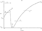
- FIG. 3 illustrates an axial thermal profile graph 300 of a parallel passage adsorbent contactor at the start of an adsorption step according to an embodiment of the present invention, showing a plot 320 of the temperature of an adsorbent material in the adsorbent contactor along the axial dimension 302 of the parallel passage adsorbent contactor from the inlet end 304 to the outlet end 306, against the temperature scale 308 of the adsorbent contactor from a lower temperature bound T1 310 to an upper temperature bound T2 312.
- the feed fluid mixture is admitted in a first axial direction 314 flowing from the inlet end 304 towards the outlet end 306 of the parallel passage adsorbent contactor.
- the temperature of the parallel passage adsorbent contactor at the start of adsorption has begun to rise at the inlet end 304 to reach temperature 322, due to the heat of adsorption released as a first fluid component begins to be adsorbed on the adsorbent material at the leading edge of the thermal front (which together with the mass transfer front comprise the adsorptive front) during the adsorption step of the present TSA method according to an embodiment of the invention. Accordingly, the lowest temperature of the contactor is shown at 328 which is slightly upstream of the inlet end 304.
- heat from the heat of adsorption of the first fluid component on at least one adsorbent material in or on the cell walls of the contactor creates a thermal spike in the parallel passage adsorbent contactor which may undesirably tend to raise the temperature of the adsorbent material and may reduce the adsorptive capacity and hence the effectiveness of the adsorbent material for removing the first fluid component from the feed fluid mixture.
- a portion of the heat from the heat of adsorption of the first fluid component may be transferred along the contactor towards the outlet end 306 by the effect of convection 316 within the contactor due to the movement of the fluid mixture admitted to the contactor and moving towards the outlet end 306.
- this convection effect 316 may only be effective to transfer heat in the same first axial direction of fluid flow 314 and therefore may act only to increase the temperature of the contactor and adsorbent material towards the outlet end 306.
- an embodiment of the present TSA method provides for the transfer of heat from the heat of adsorption of the first fluid component on the adsorbent material in the parallel passage adsorbent contactor along at least a portion of the thermally conductive filaments in the contactor in a second axial direction 318 towards the inlet end 304 of the contactor and opposite to the first axial direction of flow of the feed fluid 314 and corresponding convective heat movement 316 through the adsorbent contactor.
- Such transfer of heat in the second axial direction 318 by conduction along at least a portion of the thermally conductive filaments in the contactor, and opposite or countercurrent to the flow of feed fluid through the contactor may advantageously reduce the thermal spike in the temperature of the contactor and adsorbent material created by the heat of adsorption as the adsorptive front moves in the first axial direction 314 from the inlet end 304 towards the outlet end 306 of the adsorbent contactor, thereby desirably increasing the adsorptive capacity and hence the effectiveness of the adsorbent material.
- such countercurrent heat transfer 318 by conduction along at least a portion of thermally conductive filaments in the parallel passage adsorbent contactor may also desirably reduce the amount of thermal energy or heat which may be swept along by convection 316 with the flow of the feed fluid 314 through the contactor and removed from the contactor when the first product fluid leaves the outlet end 306 of the contactor, which would otherwise undesirably increase the required thermal energy or heat required for desorption (including heat of desorption and /or kinetic activation) of the first fluid component from the adsorbent material during a desorption or regeneration step.
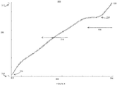
- FIG. 4 illustrates an axial thermal profile graph 400 of a parallel passage adsorbent contactor during an adsorption step according to an embodiment of the present invention showing a plot 420 of the temperature of an adsorbent material in the adsorbent contactor along the axial dimension 302 of the parallel passage adsorbent contactor from the inlet end 304 to the outlet end 306, against the temperature scale 308 of the adsorbent contactor from a lower temperature bound T1 310 to an upper temperature bound T2 312.
- the feed fluid mixture is being admitted to the contactor in a first axial direction 414 flowing from the inlet end 304 towards the outlet end 306 of the parallel passage adsorbent contactor to be recovered as the first product fluid depleted in the first fluid component, and the leading edge of the adsorptive front 422 has moved axially along the contactor during the adsorption step.
- the temperature of the parallel passage adsorbent contactor at the leading edge of the thermal front 422 (which along with the mass transfer front comprise the adsorptive front moving through the contactor during adsorption) is higher than at the inlet end of the parallel passage adsorbent contactor 426 as a portion of the heat of adsorption has moved under convection 416 in the first axial direction co-current with the flow of feed fluid mixture 414.
- heat from the heat of adsorption of the first fluid component on the adsorbent material is transferred in the second axial direction 424 countercurrent to the flow 414 of feed fluid mixture by conduction along at least a portion of the thermally conductive filaments of the parallel passage adsorbent contactor structure.
- the mass transfer front component of the adsorptive front may typically lag behind the thermal front as adsorption proceeds through the contactor, such countercurrent conduction of heat 418 along at least a portion of the thermally conductive filaments of the contactor may also advantageously allow for progression of the mass transfer front further through the adsorbent contactor towards the outlet end 306 while substantially retaining heat from the thermal front (originating from the heat of adsorption) within the adsorbent contactor, and may therefore desirably increase utilization of the adsorptive capacity of the adsorbent contactor during adsorption, increasing efficiency of the TSA method.
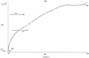
- FIG. 5 illustrates an axial thermal profile graph 500 of a parallel passage adsorbent contactor at the conclusion of an adsorption step according to an embodiment of the present invention and the beginning of a desorption step, showing a plot 520 of the temperature of an adsorbent material in the adsorbent contactor along the axial dimension 302 of the parallel passage adsorbent contactor from the inlet end 304 to the outlet end 306, against the temperature scale 308 of the adsorbent contactor from a lower temperature bound T1 310 to an upper temperature bound T2 312.
- the feed fluid mixture is no longer being admitted to the contactor
- the first product fluid depleted in the first fluid component is no longer being recovered from the outlet end 306
- a desorption or purge fluid flow 530 is now admitted to the contactor flowing from the outlet end 306 towards the inlet end 304 of the parallel passage adsorbent contactor in the second axial direction.
- the leading edge of the desorption front 528 is just entering the outlet end 306 of the contactor and will be moving axially along the contactor towards the inlet end 304 during the desorption step.
- the highest temperature 520 of the parallel passage adsorbent contactor is at the outlet end and decreases towards the edge of the desorption front 528 due to the heat of desorption required to desorb the first fluid component from the adsorbent material during the desorption step.
- an embodiment of the present TSA method provides for transfer of heat by conduction along at least a portion of the axial thermally conductive filaments in the parallel passage adsorbent contactor to provide at least a portion of the heat of desorption and/or kinetic activation required to desorb the first fluid component from the adsorbent material.
- Such transfer of heat 518 by conduction along the conductive filaments of the contactor is shown in FIG.
- the conductive transfer of heat along at least a portion of the thermally conductive filaments of the contactor may be provided in either the first or second axial directions, i.e. co-current or countercurrent to the flow of desorption or purge fluid 530, in order to provide at least a portion of the heat of desorption required to desorb the first fluid component from the adsorbent material.
- Such heat transfer may also desirably reduce any thermal dip or spike in the temperature of the adsorbent material in the contactor due to the heat of desorption, thereby increasing the effectiveness of the desorption from the adsorbent material and correspondingly increase the capacity of the adsorbent material for subsequent adsorption cycles.
- at least a portion of the heat of desorption and/or kinetic activation for an undesired adsorbed second or diluent fluid component adsorbed on the adsorbent material during such pre-regeneration step may also be provided by conductive heat transfer along the thermally conductive filaments of the contactor, for example.
- FIG. 6 illustrates an axial thermal profile graph of a parallel passage adsorbent contactor at the conclusion of a desorption or regeneration step according to an embodiment of the present invention showing a plot 620 of the temperature of an adsorbent material in the adsorbent contactor along at least a portion of the axial dimension 302 of the parallel passage adsorbent contactor from the inlet end 304 to the outlet end 306, against the temperature scale 308 of the adsorbent contactor from a lower temperature bound T1 310 to an upper temperature bound T2 312.
- the desorption or purge fluid is no longer being admitted to the contactor and the desorbed product fluid enriched in the first fluid component is no longer being recovered from the inlet end 304, and in one embodiment the contactor may be ready to begin admitting the feed fluid mixture and resuming the adsorption step of the present TSA method.
- a conditioning fluid flow 614 may be admitted to the contactor flowing from the inlet end 304 towards the outlet end 306 of the parallel passage adsorbent contactor in the first axial direction, such as to change the temperature of the adsorbent material in the contactor, or to desorb or sweep other fluid components from the contactor prior to beginning the adsorption step of the present TSA method.
- the conditioning fluid flow 614 may be admitted to the contactor to lower the temperature of the adsorbent material prior to adsorption, or to dehumidify or otherwise condition the adsorbent material.
- one embodiment of the present TSA method may provide for heat transfer 616 in the first axial direction along the parallel passage adsorbent contactor by means of convection co-current with the flow of conditioning fluid 614.
- heat transfer by conduction along at least a portion of the thermally conductive filaments of the contactor may also be provided, which may transfer heat in either the first or second axial direction such as to desirably reduce variations in the temperature of the adsorbent material in the contactor prior to adsorption.
- the highest temperature 620 of the parallel passage adsorbent contactor is at the outlet end and decreases towards the lowest temperature 628 nearest the inlet end 304 of the contactor, in preparation for resumption of the adsorption step of the present TSA method.
- adsorption of the first fluid component on the at least one adsorbent material may take place at a first adsorbent material temperature, or a first range of adsorbent material temperatures over the thermal profile of the parallel passage adsorbent contactor, which differs from a second adsorbent material temperature or range of adsorbent material temperatures at which desorption of the first fluid component takes place during a desorbing step.
- the adsorbent material may typically be heated to desorb the first fluid component, and therefore the second temperature at which desorption takes place may typically be higher than the first temperature at which adsorption of the first fluid component is performed.
- the pre-regeneration step may comprise desorbing and/or displacing at least a portion of undesirably adsorbed second or diluent fluid component from the adsorbent material, which may be conducted at another intermediate temperature or temperature range, which may preferably be between the first adsorbent material temperature during adsorption, and the second adsorbent material temperature during regeneration or desorption of the first fluid component during a desorbing step.
- the conditioning step may comprise conditioning the at least one adsorbent material to a desired pre-adsorption temperature prior to admitting the feed fluid mixture into the contactor for adsorption.
- the conditioning step may comprise admitting at least one conditioning fluid which may comprise a heat transfer fluid into the parallel passage adsorbent contactor to transfer heat to and/or from the adsorbent contactor by direct contact of the conditioning and/or heat transfer fluid with the contactor so as to condition the adsorbent material in the contactor to the desired pre-adsorption temperature.
- any suitable known conditioning and/or heat transfer fluids may be used in such a pre-conditioning step, such as but not limited to air, steam, water, coolants, condensable solvents, vapors, etc.
- the desired pre-adsorption temperature may typically be lower than the first temperature at which adsorption takes place, however, in an alternative embodiment, the pre-adsorption temperature may be higher than the first adsorption temperature, but lower than the second desorption temperature, for example.
- such a conditioning step may desirably comprise providing a secondary purge of the adsorbent material in the parallel passage adsorbent contactor, so that following a first purge during the desorption step, a secondary purge fluid stream is passed through the contactor and thereby in contact with the at least one adsorbent material to condition the adsorbent material to a desired pre-adsorption temperature and/or to further desorb or sweep one or more fluid components from the adsorbent material prior to resumption of the next adsorption step in the present TSA method, for example.
- the parallel passage adsorbent contactor may comprise at least first and second adsorbent materials, wherein at least a portion of the first fluid component is adsorbed on at least the first adsorbent material during the adsorption step.
- the first and second adsorbent materials may be comprised in separate first and second axial segments of the adsorbent contactor with one segment upstream of the other segment in the adsorbent contactor structure.
- the desorption step of the present TSA method may provide for desorbing at least a portion of the adsorbed first fluid component from the first adsorbent material by heating the first adsorbent material, separate from and substantially without heating the second adsorbent material.
- the thermally conductive filaments in the adsorbent contactor may desirably also be electrically conductive, and such separate heating of the first adsorbent material during the desorption step may be accomplished by applying an electrical current only to the filaments in contact with the first adsorbent material in order to heat the first adsorbent material and desorb the first fluid component therefrom without substantially heating the second adsorbent material.
- the desorption step of the present TSA method may additionally comprise supplying a suitable purge fluid into the parallel passage adsorbent contactor during desorption, and recovering an adsorbed product fluid comprising both the first fluid component and the purge fluid from the contactor.
- the purge fluid may be supplied to at least one of the inlet and outlet ends of the adsorbent contactor during the desorption step and may pass through the parallel passage flow channels in the adsorbent contactor in at least one of the first and second axial directions as part of the desorption of the first fluid component from the at least one adsorbent material.
- the purge fluid may also be used to provide at least a portion of the heat required to heat the adsorbent material during the desorption step (or an intermediate pre-regeneration step in an alternative embodiment) of the present TSA method.
- the adsorbent material may be heated during the desorption step by supplying at least one purge or heat transfer fluid at an elevated temperature into the parallel passage fluid contactor.
- the desorption step may comprise directly heating at least one adsorbent material to desorb the first fluid component by means of heating the thermally conductive filaments of the contactor and thereby directly heating the cell walls of the parallel passage contactor which comprise the adsorbent material.
- the thermally conductive filaments may be heated by a source of sensible heat, or alternatively in an embodiment where the thermally conductive filaments are also electrically conductive, the filaments, and thereby the adsorbent material in the cell walls of the contactor may be directly heated by passing an electrical current through the filaments such as by electrical resistance or joule heating of the filaments.
- the use of electrical resistance or joule heating of the conductive filaments in the contactor to directly and precisely heat the adsorbent material(s) during desorption may desirably provide for reduced cycle times for the TSA methods of the invention, and may allow for reduction of the conventionally long (typically hours or more) cycle durations to significantly shorter cycle durations such as TSA steps (such as adsorption, desorption, etc.) of less than two minutes, and preferably less than 90 seconds in duration, for example.
- the desorption step may comprise desorbing at least a portion of the adsorbed first fluid component from the first adsorbent material by electrically heating the conductive filaments in the first axial segment of the contactor separately from the second adsorbent material in the second axial segment.
- the first and second axial segments may be sequentially heated such as by electrical resistance heating of the first and second segments individually during the desorption step of the present TSA method.
- first axial segment may be located nearest to the outlet end of the contactor and the second axial segment may be located towards the inlet end of the contactor from the first segment, and corresponding to the sequential desorption of the first and second axial segments first and second desorbed product fluids enriched in the first fluid component and another fluid component desorbed from the second adsorbent material may be recovered from the inlet or outlet end (depending upon the direction of fluid flow through the contactor during desorption) during the recovery step of the present TSA method.
- any suitable known adsorbent material such as those which may be used to adsorb a desired fluid component of the feed fluid mixture may be used in conjunction with the TSA method as the adsorbent material(s) comprised in and/or on the cell walls of the parallel passage adsorbent contactor(s).
- adsorbent material may desirably provide a sufficiently high dynamic selectivity (such as comprising equilibrium and/or kinetic selectivity) of a first fluid component relative to the remaining components of the feed fluid, over the TSA cycle.
- any suitable known adsorbent materials may be comprised in each of the contactor segments so as to provide for desired adsorption of one or more fluid components from the feed fluid mixture.
- the adsorbent contactor may comprise multiple separate segments or sections comprising the same adsorbent material or combination of adsorbent materials, and in another embodiment, the adsorbent contactor may comprise a different adsorbent material (or combination of adsorbent materials) comprised in each of the contactor segments or sections, such as to selectively adsorb different fluid components of the feed fluid mixture during an adsorption step of the present TSA method.
- the adsorbent materials may be selected so as to be compatible with each other for adsorption of the particular feed fluid components and at the intended adsorption and desorption conditions, for example.
- Exemplary known adsorbent materials which may be suitable for use in selected embodiments of the present TSA method may comprise, but are not limited to: desiccant, activated carbon, carbon adsorbent, graphite, carbon molecular sieve, activated alumina, molecular sieve, aluminophosphate, silicoaluminophosphate, zeolite adsorbent, ion exchanged zeolite, hydrophilic zeolite, hydrophobic zeolite, modified zeolite, natural zeolites, faujasite, clinoptilolite, mordenite, metal-exchanged silico-aluminophosphate, uni-polar resin, bi-polar resin, aromatic cross-linked polystyrenic matrix, brominated aromatic matrix, methacrylic ester copolymer, graphitic adsorbent, carbon fiber, carbon nanotube, nano-materials, metal salt adsorbent, perchlorate, oxalate, alka
- the steps of the TSA method may be desirably conducted under substantially constant or isobaric pressure conditions.
- the admission of feed fluid to the adsorbent contactor, adsorption of a fluid component, recovery of a first product fluid, desorption of an adsorbed component, and recovery of a desorbed second product fluid may all be conducted under substantially atmospheric pressure, for example.
- steps of the TSA method may be conducted at a substantially constant elevated pressure, such as under isobaric super-atmospheric conditions, for example.
- the admitting, adsorbing and recovering a first product fluid steps of the present TSA method may be conducted under a first substantially constant pressure condition, such as under atmospheric pressure, for example, while the desorbing and recovering a desorbed second product fluid steps may be conducted at an elevated pressure, such as an elevated super-atmospheric pressure.
- the adsorbent contactor may be substantially sealed prior to the desorbing step, and the heating of the adsorbent contactor conducted during the adsorbing step may result in increased pressure within the contactor as the adsorbed fluid component desorbs from the adsorbent material, thereby raising the pressure of the contactor to a super-atmospheric level, for example.
- the desorbed second product fluid may optionally be recovered at a desirably elevated pressure above the pressure at which the adsorbing steps were conducted, so as to provide a pressurized second product fluid which may be desirable in certain applications.
- a temperature swing adsorption (TSA) process particularly directed to separating carbon dioxide gas from a flue gas feed mixture comprising at least carbon dioxide and nitrogen components.
- TSA temperature swing adsorption
- Such a TSA process for separating carbon dioxide may be particularly adapted for removing at least a portion of carbon dioxide from the flue gas or exhaust of a thermal power plant, such as a coal or natural gas power plant for example.
- a temperature swing adsorption (TSA) process is provided for separating at least a carbon dioxide component from the flue gas feed fluid mixture comprising at least carbon dioxide and nitrogen.
- the TSA process may comprise an initial step of admitting the flue gas feed mixture into an adsorptive separation system which comprises at least one parallel passage adsorbent contactor.
- suitable such parallel passage adsorbent contactors may comprise a plurality of substantially parallel fluid flow passages oriented in a first axial direction between and inlet and outlet end of the contactor in order to permit fluid to flow through the contactor, and cell walls which comprise at least one carbon dioxide adsorbent material situated between and separating the fluid flow passages.
- the parallel passage adsorbent contactor may also desirably comprise a plurality of axially continuous thermally conductive filaments oriented in the axial direction of the contactor and in direct contact with the at least one carbon dioxide adsorbent material comprised in or on the cell walls of the contactor.
- the flue gas may then be admitted into the inlet end of the parallel passage adsorbent contactor to flow in a first axial direction through the contactor towards the outlet end, and at least a portion of the carbon dioxide component may be adsorbed on the at least one carbon dioxide adsorbent material, which may preferably be selective for adsorbing carbon dioxide over nitrogen and/or other components of the flue gas mixture.
- heat released from the heat of adsorption of the carbon dioxide component on the at least one carbon dioxide adsorbent material is then transferred along at least a portion of the thermally conductive filaments in the adsorbent contactor in a second axial direction (opposite in direction to the first axial direction) back along the contactor towards the inlet end of the contactor during the adsorption of carbon dioxide on the carbon dioxide adsorbent material.
- Such transfer of heat in the second axial direction may desirably reduce a spike in the temperature of the at least one carbon dioxide adsorbent as adsorption of carbon dioxide occurs, and optionally also desirably retain at least a significant portion of the heat energy from the heat of adsorption within the adsorbent contactor to allow recovery of such thermal energy during later regeneration of the carbon dioxide adsorbent material.
- a flue gas product stream depleted in carbon dioxide relative to the flue gas feed mixture is then recovered from the outlet end of the adsorbent contactor.
- such first product fluid may desirably comprise a substantially carbon dioxide-free flue gas product stream, which may then be vented to atmosphere or otherwise treated or processed prior to release and which may therefore be expected to have a significantly lessened impact on carbon emissions due to the removal of carbon dioxide, as may be desirable for reducing impact on atmospheric carbon dioxide levels for example.
- At least a portion of the carbon dioxide adsorbed on the at least one carbon dioxide adsorbent material is then desorbed by heating the at least one adsorbent material, and heat is transferred in either of the first or second axial directions along at least a portion of the thermally conductive filaments of the adsorbent contactor to provide at least a portion of the heat of desorption of the carbon dioxide from the adsorbent material which is required during the desorption step.
- a desorbed carbon dioxide product enriched in carbon dioxide is recovered from at least one of the inlet and outlet ends of the parallel passage adsorbent contactor.
- an adsorptive separation system for operation according to the present TSA carbon dioxide separation process may desirably comprise two or more such parallel passage adsorbent contactors, so as to provide for staggered operation of the present TSA separation process and allow continuous and/or semi-continuous adsorptive separation from a source of flue gas such as a thermal power plant, for example.
- any suitable known adsorptive separation system using mechanical/pneumatic or other types of valves or other flow control devices for example may be used to implement the gas flows of the steps of the present TSA process, as are known in the art for systems comprising one, two, or three or more adsorbers containing adsorbent material.
- an adsorptive separation system suitable for implementing the carbon dioxide separation process comprises at least one parallel passage adsorbent contactor which each comprise a plurality of substantially parallel fluid flow passages oriented in a first axial direction between and inlet and outlet end of the contactor in order to permit gas to flow through the contactor, and cell walls which comprise at least one carbon dioxide selective adsorbent material situated between and separating the fluid flow passages.
- Each suitable such parallel passage adsorbent contactor further comprises a plurality of axially continuous thermally conductive filaments oriented in the axial direction of the contactor and in direct contact with the at least one carbon dioxide adsorbent material comprised in the cell walls of the contactor.
- the TSA carbon dioxide separation process may also comprise a conditioning step to condition at least one carbon dioxide adsorbent in the adsorbent contactor(s) to a desired pre-adsorption temperature prior to admitting the flue gas feed mixture and adsorption of carbon dioxide.
- a conditioning step may comprise conditioning at least one carbon dioxide adsorbent material to any desired or suitable pre-adsorption temperature, such as a temperature lower than an adsorption temperature of the carbon dioxide adsorbent during an adsorption step of the TSA process, or higher than the adsorption temperature but lower than a desorption temperature of the adsorbent during a desorption step of the TSA process, for example.
- the adsorption temperature of the carbon dioxide adsorbent may desirably be lower than the desorption temperature during a desorption step, such that the desorption of carbon dioxide from the adsorbent may be accomplished by heating the adsorbent material, such as by direct heating of the thermally conductive filaments in the adsorbent contactor, for example.
- the TSA carbon dioxide separation process may be applied to separate carbon dioxide from the flue gas from a thermal power plant such as a coal fired boiler flue gas, so as to desirably substantially remove the carbon dioxide from the flue gas to allow capture of the carbon dioxide and thereby significantly decrease carbon emissions of the power plant.
- a thermal power plant such as a coal fired boiler flue gas
- the coal fired boiler flue gas feed mixture may comprise approximately 12% carbon dioxide, 84% nitrogen and oxygen, and 4% water vapor, and may be supplied at approximately atmospheric pressure (101.3kPa) and at a temperature of about 40 C, for example.
- a suitable carbon dioxide adsorbent material may be used in the parallel passage adsorbent contactor(s) of the adsorptive separation system to adsorb substantially all of the carbon dioxide from the flue gas during the adsorption step of the TSA process, and to recover a substantially carbon dioxide-free flue gas product stream.
- At least one carbon dioxide selective adsorbent material comprised in the parallel passage adsorbent contactor may desirably be dynamically selective for adsorption of carbon dioxide over nitrogen or other diluent components of the flue gas mixture, such that a dynamic selectivity for carbon dioxide is sufficiently high to usably provide substantially complete carbon dioxide separation.
- Such dynamic selectivity over the cycle of the TSA separation method may comprise at least one of an equilibrium selectivity of the at least one adsorbent material for carbon dioxide, and a kinetic selectivity of the at least one adsorbent material for carbon dioxide.
- the flue gas mixture may be admitted to the adsorbent contactor at a space velocity (Vgas/Vads/t) less than the mass transfer rate (1/s) of carbon dioxide, but greater than the mass transfer rate (1/s) of nitrogen or other diluent components, such that the adsorption step may comprise at least a kinetic selectivity based on the mass transfer rates of carbon dioxide and nitrogen on the adsorbent material at the adsorbent temperature during the adsorption step.
- Vgas/Vads/t space velocity less than the mass transfer rate (1/s) of carbon dioxide, but greater than the mass transfer rate (1/s) of nitrogen or other diluent components
- a steam purge gas may be supplied to the adsorbent contactor such as from the outlet end at a temperature of about 130 C and pressure of about 105 kPa to assist in desorption along with the heating of the adsorbent with the thermally conductive filaments in the contactor.
- a portion of the steam purge gas may be adsorbed by the adsorbent material which may release heat due to the heat of adsorption of the steam, which heat may also be transferred axially along the contactor by the thermally conductive filaments, which may desirably further provide a portion of the heat of desorption necessary for continued desorption of carbon dioxide.
- the recovered carbon dioxide product from the adsorbent contactor may desirably be highly concentrated in carbon dioxide such as to allow for compression, storage, sequestration, or alternative industrial use (such as for injection use in enhanced oil recovery for example) of the carbon dioxide removed from the flue gas.
- the steam component of the recovered carbon dioxide product stream may desirably be condensed in order to remove it from the product stream, thereby resulting in increased purity of the carbon dioxide product.
- the purge gas may also comprise at least one of ambient air, steam, and a flue gas product stream depleted of carbon dioxide.
- a heat transfer fluid may also be admitted to the contactor during the desorption step, such as at an elevated temperature to heat the adsorbent material, and may be used in addition to or in place of a purge gas.
- Such heat transfer fluid may comprise at least one of ambient air, steam, a carbon dioxide enriched product gas, or a flue gas product stream depleted of carbon dioxide, for example.
- the carbon dioxide adsorbent material may also be directly heated by heating the thermally conductive filaments in the adsorbent contactor, such as by applying sensible heat to the filaments, or in the case of electrically conductive filaments, applying an electrical current to directly heat the filaments by electrical resistance or joule heating.
- the TSA process may additionally comprise an intermediate recycle or pre-regeneration step in which a limited amount of heat is provided to the adsorbent material to heat the contactor to an intermediate temperature sufficient to desorb at least a portion of an undesired nitrogen (or other diluent) component co-adsorbed on the adsorbent material.
- the adsorbent material may be heated using any suitable means, such as one or more of: providing a heated purge gas, heated recycle gas or heated carbon dioxide product gas to the adsorbent contactor, and/or direct or electrically heating the conductive filaments in the adsorbent contactor, for example.
- the resulting recycle stream leaving the adsorbent contactor during such step may then be recycled within the TSA process such as to provide heat for another desorption or pre-regeneration step and/or recycled to the feed stream for re-admission during subsequent adsorption or feed steps.
- the present TSA process may also comprise a conditioning step where ambient air at less than about 40 C and at substantially atmospheric pressure (101.3kPa) may be admitted at the inlet end of the contactor, to condition the adsorbent material prior to resuming the adsorption step on the next cycle.
- the conditioning step may desirably cool the adsorbent material by removal of sensible heat from the adsorbent material by the ambient air, and also to remove at least a portion of the water adsorbed on the adsorbent material from the steam purge gas, thereby drying the adsorbent material prior to the next adsorption step, and also further cooling the adsorbent material due to the heat removed by desorption of the water from the adsorbent material during drying.
- such cooling step using air as a cooling fluid may result in adsorption of at least a portion of nitrogen or other diluents on the adsorbent material, thereby necessitating the above-described pre-regeneration or recycle step in order to preserve high purity in the desorbed carbon dioxide product recovered during the regeneration of the adsorbent contactor, as may be desirable for carbon sequestration, compression and/or enhanced oil recovery injection of carbon dioxide applications.
- any suitable known carbon dioxide adsorbent material may be used in the parallel passage adsorbent contactor(s) of the adsorptive separation system to adsorb carbon dioxide during the adsorption step of the process.
- Such carbon dioxide adsorbents may comprise, but are not limited to: activated carbon adsorbent, amine impregnated adsorbent supports (comprising silica, activated carbon, carbon molecular sieve, alumina, zeolite, polymer and ceramic supports), metal salt, metal hydroxide, metal oxide, zeolite, hydrotalcite, silicalite, metal organic framework and zeolitic imadazolate framework adsorbent materials, and combinations thereof.
- a suitable carbon dioxide adsorbent material may be selected that may also desirably be selective for the adsorption of carbon dioxide over any other gas components of the flue gas feed mixture, for example.
- such suitable carbon dioxide selective adsorbent material may desirably be tailored for high dynamic selectivity of carbon dioxide over nitrogen.
- Such desirable high dynamic selectivity carbon dioxide adsorbent may thereby be chosen so as to maximize equilibrium and kinetic selectivity for carbon dioxide over nitrogen (and/or other diluents fluid species) in a cyclic TSA process by either selecting an adsorbent with such characteristics or tailoring the properties of the parallel passage contactor and/or modifying the surface characteristics of adsorbent material comprised in the parallel passage contactor such as by modifying the adsorbent material pore size, pore throat, pocket size, etc., to improve equilibrium and/or kinetic selectivity of carbon dioxide, for example.
- the adsorbent contactor may comprise at least one first carbon dioxide adsorbent and also at least one second adsorbent material.
- first and second adsorbent materials may comprise similar or different adsorbent materials and may be comprised in first and second segments of the adsorbent contactor, such as first and second axial segments for example.
- the desorption step of the TSA carbon dioxide separation process may comprise desorbing at least a portion of the adsorbed carbon dioxide from the first adsorbent material by electrically heating the conductive filaments in the first axial segment of the contactor separately from the second adsorbent material in the second axial segment.
- first and second axial segments may be sequentially heated such as by electrical resistance heating of the first and second segments individually during the desorption step of the present TSA method, so as to produce a separate first carbon dioxide rich product gas, and a second product gas enriched in another flue gas component desorbed from the second adsorbent material.
- first axial segment may be located nearest to the outlet end of the contactor and the second axial segment may be located towards the inlet end of the contactor from the first segment, and corresponding to the sequential desorption of the first and second axial segments first and second desorbed product fluids enriched in carbon dioxide and another flue gas component desorbed from the second adsorbent material may be recovered from the inlet or outlet end (depending upon the direction of fluid flow through the contactor during desorption) during the recovery step of the present TSA method.
- three or more axial segments and corresponding adsorbent materials may be implemented including the first carbon dioxide adsorbent, and may thereby be sequentially and individually desorbed in order to produce a separate carbon dioxide enriched product streams and corresponding other product streams which may be recovered separately from the adsorbent contactor.
- a second adsorbent material selective for at least one of water, nitrogen oxides, sulfur oxides and heavy metals over carbon dioxide, respectively, and optionally also a third adsorbent material selective for at least one of water, nitrogen oxides, sulfur oxides and heavy metals over carbon dioxide may be implemented in separate second and third axial segments in addition to the carbon dioxide adsorbent in a first axial segment of the contactor, such that the second axial segment is located upstream of said first axial segment nearer to the inlet end of said contactor, and wherein said third axial segment is located upstream of said first axial segment and downstream of said second axial segment.
- Such second and third adsorbent materials may thereby be used to desirably separate other contaminants from the flue gas stream which may be separately desorbed and recovered such as for containment and/or disposal separate from the carbon dioxide product.
- the steps of the TSA process may be desirably conducted under substantially constant or isobaric pressure conditions.
- the admission of the flue gas feed mixture to the adsorbent contactor, adsorption of carbon dioxide, recovery of a flue gas product stream, desorption of carbon dioxide, and recovery of a desorbed carbon dioxide stream may all be conducted under substantially atmospheric pressure, for example.
- steps of the present TSA process may be conducted at a substantially constant elevated pressure, such as under isobaric super-atmospheric conditions, for example.
- the admitting, adsorbing and recovering a flue gas product stream steps of the present TSA process may be conducted under a first substantially constant pressure condition, such as under atmospheric pressure, for example, while the desorbing and recovering a desorbed carbon dioxide product steps may be conducted at an elevated pressure, such as an elevated super-atmospheric pressure.
- the adsorbent contactor may be substantially sealed prior to the desorbing step, and the heating of the adsorbent contactor conducted during the adsorbing step may result in increased pressure within the contactor as the adsorbed carbon dioxide desorbs from the adsorbent material, thereby raising the pressure of the contactor to a super-atmospheric level, for example.
- the desorbed carbon dioxide product fluid may optionally be recovered at a desirably elevated pressure above the pressure at which the adsorbing steps were conducted, so as to provide a pressurized carbon dioxide product stream which may be desirable in certain applications, such as where further compression of the carbon dioxide may be required for transport, storage, sequestration or industrial use.
- the temperature swing adsorption (TSA) carbon dioxide separation process may be particularly directed to separating carbon dioxide gas from a natural gas feed mixture in place of a flue gas feed mixture.
- the natural gas feed mixture may comprise at least methane and carbon dioxide components, and may also comprise hydrogen sulfide or other contaminants.
- TSA process for separating carbon dioxide from natural gas may be particularly adapted for removing at least a portion of the carbon dioxide and/or hydrogen sulfide from a contaminated natural gas feed mixture, as may be encountered in applications such as shale gas, low concentration natural gas fields or end of well life natural gas sources, for example.
- the TSA carbon dioxide separation process may be relatively similar to that for flue gas separation, substituting the natural gas feed stream for the flue gas.
- Any suitable adsorbent material may be comprised in the adsorbent contactor(s) of the adsorptive separation system which are desirably selective for carbon dioxide and/or hydrogen sulfide over other natural gas components, and preferably desirably dynamically selective (comprising equilibrium and/or kinetic selectivity) for carbon dioxide and/or hydrogen sulfide (or other undesirable diluent components) over methane over the cyclic TSA process.
- such suitable carbon dioxide selective adsorbent material may desirably be tailored for high dynamic selectivity of carbon dioxide over methane.
- Such desirable high dynamic selectivity carbon dioxide adsorbent may thereby be chosen so as to maximize equilibrium and kinetic selectivity for carbon dioxide over methane in a cyclic TSA process by either selecting an adsorbent with such characteristics or tailoring the properties of the parallel passage contactor and/or modifying the surface characteristics of adsorbent material comprised in the parallel passage contactor such as by modifying the adsorbent material pore size, pore throat, pocket size, etc., to improve equilibrium and/or kinetic selectivity of carbon dioxide, for example.
- such natural gas carbon dioxide separation processes may typically be conducted at isobaric super-atmospheric pressures associated with pressurized natural gas feed mixture sources such as wells and/or pipelines, for example.
Applications Claiming Priority (2)
| Application Number | Priority Date | Filing Date | Title |
|---|---|---|---|
| US37787510P | 2010-08-27 | 2010-08-27 | |
| EP11819258.2A EP2608867B8 (de) | 2010-08-27 | 2011-08-26 | Verfahren für adsorptive gastrennung mit einer wärmeleitenden schützstruktur |
Related Parent Applications (2)
| Application Number | Title | Priority Date | Filing Date |
|---|---|---|---|
| EP11819258.2A Division EP2608867B8 (de) | 2010-08-27 | 2011-08-26 | Verfahren für adsorptive gastrennung mit einer wärmeleitenden schützstruktur |
| EP11819258.2A Division-Into EP2608867B8 (de) | 2010-08-27 | 2011-08-26 | Verfahren für adsorptive gastrennung mit einer wärmeleitenden schützstruktur |
Publications (1)
| Publication Number | Publication Date |
|---|---|
| EP3153223A1 true EP3153223A1 (de) | 2017-04-12 |
Family
ID=45722797
Family Applications (2)
| Application Number | Title | Priority Date | Filing Date |
|---|---|---|---|
| EP16198431.5A Withdrawn EP3153223A1 (de) | 2010-08-27 | 2011-08-26 | Adsorptive gastrennung mit einer wärmeleitenden struktur |
| EP11819258.2A Active EP2608867B8 (de) | 2010-08-27 | 2011-08-26 | Verfahren für adsorptive gastrennung mit einer wärmeleitenden schützstruktur |
Family Applications After (1)
| Application Number | Title | Priority Date | Filing Date |
|---|---|---|---|
| EP11819258.2A Active EP2608867B8 (de) | 2010-08-27 | 2011-08-26 | Verfahren für adsorptive gastrennung mit einer wärmeleitenden schützstruktur |
Country Status (7)
| Country | Link |
|---|---|
| US (2) | US8900347B2 (de) |
| EP (2) | EP3153223A1 (de) |
| JP (1) | JP5904420B2 (de) |
| CN (1) | CN103180028B (de) |
| AU (1) | AU2011293018B2 (de) |
| CA (4) | CA3045687A1 (de) |
| WO (1) | WO2012024804A1 (de) |
Families Citing this family (72)
| Publication number | Priority date | Publication date | Assignee | Title |
|---|---|---|---|---|
| AU2011293018B2 (en) | 2010-08-27 | 2015-11-12 | Inventys Thermal Technologies Inc. | Method of adsorptive gas separation using thermally conductive contactor structure |
| US10315159B2 (en) | 2010-08-27 | 2019-06-11 | Inventys Thermal Technoogies Inc. | Method of adsorptive gas separation using thermally conductive contactor structure |
| CA2964550C (en) | 2011-07-02 | 2019-07-23 | Inventys Thermal Technologies Inc. | System and method for integrated adsorptive gas separation of combustion gases |
| US8686083B2 (en) * | 2011-11-08 | 2014-04-01 | Battelle Energy Alliance, Llc | Composite media for fluid stream processing, a method of forming the composite media, and a related method of processing a fluid stream |
| JP6328098B2 (ja) * | 2012-03-29 | 2018-05-23 | フィリップス ライティング ホールディング ビー ヴィ | 暖房デバイス及び暖房方法 |
| CN103566625B (zh) * | 2012-08-07 | 2015-10-28 | 香港城市大学 | 化合物的分离方法 |
| US9604889B2 (en) | 2012-11-08 | 2017-03-28 | Energy Recovery, Inc. | Isobaric pressure exchanger in amine gas processing |
| US9440895B2 (en) | 2012-11-08 | 2016-09-13 | Energy Recovery, Inc. | Isobaric pressure exchanger controls in amine gas processing |
| EP2938425A4 (de) | 2012-12-31 | 2016-11-23 | Inventys Thermal Technologies Inc | System und verfahren zur integrierten kohlendioxidabscheidung aus verbrennungsgasen |
| AR096132A1 (es) | 2013-05-09 | 2015-12-09 | Exxonmobil Upstream Res Co | Separar dióxido de carbono y sulfuro de hidrógeno de un flujo de gas natural con sistemas de co-corriente en contacto |
| US9308486B2 (en) | 2013-11-20 | 2016-04-12 | L'Air Liquide, Société Anonyme pour l'Etude et l'Exploitation des Procédés Georges Claude | Method of using a structured adsorbent bed for capture of CO2 from low pressure and low pressure concentration sources |
| US9314731B2 (en) | 2013-11-20 | 2016-04-19 | L'Air Liquide, Société Anonyme pour l'Etude et l'Exploitation des Procédés Georges Claude | RTSA method using adsorbent structure for CO2 capture from low pressure and low concentration sources |
| JP6107695B2 (ja) * | 2014-02-10 | 2017-04-05 | 日立化成株式会社 | 二酸化炭素回収装置及び二酸化炭素回収方法 |
| US9675925B2 (en) | 2014-07-25 | 2017-06-13 | Exxonmobil Upstream Research Company | Apparatus and system having a valve assembly and swing adsorption processes related thereto |
| JP6776233B2 (ja) | 2014-11-11 | 2020-10-28 | エクソンモービル アップストリーム リサーチ カンパニー | ペーストインプリンティングによる高容量の構造体及びモノリス |
| EP3229938A1 (de) | 2014-12-10 | 2017-10-18 | ExxonMobil Research and Engineering Company | Polymerfasern mit integriertem adsorbens in gepacktem bett und gewebeschütz sowie verfahren und vorrichtungen mit verwendung davon |
| RU2666849C1 (ru) | 2014-12-23 | 2018-09-12 | Эксонмобил Апстрим Рисерч Компани | Структурированный слой адсорбента, способы его получения и его применение |
| EP3037473B1 (de) | 2014-12-24 | 2017-11-08 | Solvay SA | Zusammensetzungen mit Vinylidenfluoridpolymeren und adsorbierenden Kohlenstoffmaterialien |
| MX2017007708A (es) | 2015-01-09 | 2017-10-27 | Exxonmobil Upstream Res Co | Separando impurezas de una corriente de fluido usando contactores multiples de corrientes en igual sentido. |
| DE102015200679A1 (de) * | 2015-01-16 | 2016-07-21 | Areva Gmbh | Belüftungssystem und zugehöriges Betriebsverfahren zum Einsatz während eines schweren Störfalls in einer kerntechnischen Anlage |
| WO2016133647A1 (en) | 2015-02-17 | 2016-08-25 | Exxonmobil Upstream Research Company | Inner surface featurees for co-current contactors |
| CA2978899C (en) | 2015-03-13 | 2019-09-17 | Exxonmobil Upstream Research Company | Coalescer for co-current contactors |
| US10080991B2 (en) | 2015-09-02 | 2018-09-25 | Exxonmobil Upstream Research Company | Apparatus and system for swing adsorption processes related thereto |
| CN107847851B (zh) | 2015-09-02 | 2021-05-18 | 埃克森美孚上游研究公司 | 使用脱甲烷塔顶部流作为清扫气体的变化吸附方法和系统 |
| US10029205B2 (en) | 2015-09-25 | 2018-07-24 | Exxonmobil Research And Engineering Company | Two stage adsorbent and process cycle for fluid separations |
| US10016716B2 (en) | 2015-09-25 | 2018-07-10 | Exxonmobil Research And Engineering Company | Swing adsorber and process cycle for fluid separations |
| CN106556211A (zh) * | 2015-09-30 | 2017-04-05 | 青岛海尔智能技术研发有限公司 | 一种压力平衡装置及具有该压力平衡装置的冷藏设备 |
| WO2017074657A1 (en) | 2015-10-27 | 2017-05-04 | Exxonmobil Upstream Research Company | Apparatus and system for swing adsorption processes related thereto having actively-controlled feed poppet valves and passively controlled product valves |
| JP6616011B2 (ja) | 2015-10-27 | 2019-12-04 | エクソンモービル アップストリーム リサーチ カンパニー | 複数の弁を有するスイング吸着プロセス用の装置及びシステム |
| AU2016344415B2 (en) | 2015-10-27 | 2019-08-22 | Exxonmobil Upstream Research Company | Apparatus and system for swing adsorption processes related thereto having a plurality of valves |
| CN106669636B (zh) * | 2015-11-11 | 2019-08-27 | 中国科学院大连化学物理研究所 | 一种规整结构吸附剂及其应用 |
| RU2018121824A (ru) | 2015-11-16 | 2019-12-20 | Эксонмобил Апстрим Рисерч Компани | Адсорбирующие материалы и способы адсорбции диоксида углерода |
| US10788406B2 (en) | 2015-12-14 | 2020-09-29 | Panasonic Corporation | Chemical substance concentrator and chemical substance detector |
| US10413858B2 (en) * | 2015-12-28 | 2019-09-17 | Arizona Board Of Regents On Behalf Of Arizona State University | Metal-organic framework-based sorbents and methods of synthesis thereof |
| CN106931730A (zh) * | 2015-12-30 | 2017-07-07 | 青岛海尔智能技术研发有限公司 | 转轮式干燥器及制冷设备 |
| EP3216511A1 (de) * | 2016-03-08 | 2017-09-13 | Casale SA | Temperaturwechseladsorptionsverfahren |
| EP3216512A1 (de) * | 2016-03-08 | 2017-09-13 | Casale SA | Temperaturwechseladsorptionsverfahren |
| EP3429727A1 (de) | 2016-03-18 | 2019-01-23 | Exxonmobil Upstream Research Company | Vorrichtung und system für wechseladsorptionsprozesse im zusammenhang damit |
| JP6671204B2 (ja) * | 2016-03-24 | 2020-03-25 | 大阪瓦斯株式会社 | ガス分離装置 |
| CN107754759A (zh) * | 2016-03-31 | 2018-03-06 | 烟台智本知识产权运营管理有限公司 | 一种变压吸附分离甲烷氮气用的复合吸附剂的制备方法 |
| CN109416176B (zh) * | 2016-03-31 | 2021-08-31 | 英万茨热科技有限公司 | 包括温度摇摆吸附气体分离的燃烧系统 |
| JP6980686B2 (ja) * | 2016-03-31 | 2021-12-15 | スヴァンテ インコーポレイテッド | 低熱導電率吸着ガス分離器 |
| RU2716686C1 (ru) | 2016-05-31 | 2020-03-13 | Эксонмобил Апстрим Рисерч Компани | Устройство и система для осуществления процессов короткоцикловой адсорбции |
| CN109219476A (zh) | 2016-05-31 | 2019-01-15 | 埃克森美孚上游研究公司 | 用于变吸附方法的装置和系统 |
| US10434458B2 (en) | 2016-08-31 | 2019-10-08 | Exxonmobil Upstream Research Company | Apparatus and system for swing adsorption processes related thereto |
| WO2018044501A1 (en) | 2016-09-01 | 2018-03-08 | Exxonmobil Upstream Research Company | Swing adsorption processes for removing water using 3a zeolite structures |
| US10328382B2 (en) | 2016-09-29 | 2019-06-25 | Exxonmobil Upstream Research Company | Apparatus and system for testing swing adsorption processes |
| EP3528941A1 (de) | 2016-10-21 | 2019-08-28 | Corning Incorporated | Sorptionsstrukturen mit widerstandsheizungsfähigkeit und verfahren zur herstellung davon |
| US11766634B2 (en) | 2016-11-08 | 2023-09-26 | Svante Inc. | Parallel passage contactor and method of adsorptive gas separation |
| US10549230B2 (en) | 2016-12-21 | 2020-02-04 | Exxonmobil Upstream Research Company | Self-supporting structures having active materials |
| CA3045034C (en) | 2016-12-21 | 2021-06-29 | Exxonmobil Upstream Research Company | Self-supporting structures having active materials |
| AU2018286407B2 (en) | 2017-06-15 | 2021-07-01 | Exxonmobil Upstream Research Company | Fractionation system using compact co-current contacting systems |
| US11260342B2 (en) | 2017-06-15 | 2022-03-01 | Exxonmobil Upstream Research Company | Fractionation system using bundled compact co-current contacting systems |
| CA3067524C (en) | 2017-06-20 | 2023-05-09 | Exxonmobil Upstream Research Company | Compact contacting systems and methods for scavenging sulfur-containing compounds |
| SG11201911582UA (en) * | 2017-07-19 | 2020-02-27 | Exxonmobil Res & Eng Co | Use of type v adsorbent and gas concentration for c02 adsorption and capture |
| BR112020002885A2 (pt) | 2017-08-21 | 2020-07-28 | Exxonmobil Upstream Research Company | integração de solvente frio e remoção de gás ácido |
| EP3449996A1 (de) * | 2017-08-28 | 2019-03-06 | Casale Sa | Temperaturwechseladsorptionsverfahren |
| EP3449997A1 (de) * | 2017-08-28 | 2019-03-06 | Casale Sa | Temperaturwechseladsorptionsverfahren |
| US10563555B2 (en) | 2017-10-19 | 2020-02-18 | Saudi Arabian Oil Company | Rotary contactor for vehicle carbon dioxide capture |
| US11331620B2 (en) | 2018-01-24 | 2022-05-17 | Exxonmobil Upstream Research Company | Apparatus and system for swing adsorption processes |
| EP3758828A1 (de) | 2018-02-28 | 2021-01-06 | ExxonMobil Upstream Research Company | Vorrichtung und system für wechseladsorptionsprozesse |
| CN110871014A (zh) * | 2018-08-30 | 2020-03-10 | 开利公司 | 具有移动床结构的co2洗涤器 |
| CN109354137B (zh) * | 2018-11-27 | 2021-07-30 | 浙江工业大学 | 碳纳米管/mof衍生多孔碳复合电极材料的制备及应用 |
| US11318410B2 (en) | 2018-12-21 | 2022-05-03 | Exxonmobil Upstream Research Company | Flow modulation systems, apparatus, and methods for cyclical swing adsorption |
| WO2020222932A1 (en) | 2019-04-30 | 2020-11-05 | Exxonmobil Upstream Research Company | Rapid cycle adsorbent bed |
| WO2021071755A1 (en) | 2019-10-07 | 2021-04-15 | Exxonmobil Upstream Research Company | Adsorption processes and systems utilizing step lift control of hydraulically actuated poppet valves |
| WO2021076594A1 (en) | 2019-10-16 | 2021-04-22 | Exxonmobil Upstream Research Company | Dehydration processes utilizing cationic zeolite rho |
| US20220082042A1 (en) * | 2020-09-17 | 2022-03-17 | Advanced Technology Emission Solutions Inc. | Apparatus and method for gaseous emissions treatment with resistive heating |
| US11717784B1 (en) | 2020-11-10 | 2023-08-08 | Solid State Separation Holdings, LLC | Natural gas adsorptive separation system and method |
| CN113398686A (zh) * | 2021-07-29 | 2021-09-17 | 瑞燃(上海)环境工程技术有限公司 | 一种电子元件及电子专用材料生产废气过滤及吸附材料 |
| KR102546112B1 (ko) * | 2021-10-22 | 2023-06-22 | 한국과학기술원 | 전기화된 파이버 흡착제의 제조방법 및 전기 및 전자기 스윙 흡착 공정 |
| WO2023215973A1 (en) * | 2022-05-10 | 2023-11-16 | Hydron Energy Inc. | System and process for gas upgrading |
Citations (2)
| Publication number | Priority date | Publication date | Assignee | Title |
|---|---|---|---|---|
| US6652627B1 (en) * | 2002-10-30 | 2003-11-25 | Velocys, Inc. | Process for separating a fluid component from a fluid mixture using microchannel process technology |
| WO2010096916A1 (en) * | 2009-02-27 | 2010-09-02 | Andre Boulet | Parallel passage fluid contactor structure |
Family Cites Families (69)
| Publication number | Priority date | Publication date | Assignee | Title |
|---|---|---|---|---|
| US2989383A (en) * | 1958-02-14 | 1961-06-20 | Fluor Corp | Solid adsorber |
| US3713281A (en) * | 1971-11-02 | 1973-01-30 | G Asker | Heat and moisture exchange packing |
| JPS6261614A (ja) * | 1985-09-10 | 1987-03-18 | Aoki Kensetsu:Kk | 滅菌フイルタ− |
| DE3712333A1 (de) | 1987-04-11 | 1988-10-20 | Fev Motorentech Gmbh & Co Kg | Regenerierbare filteranordnung zum entfernen von russpartikeln aus abgasen |
| US5232882A (en) | 1989-05-19 | 1993-08-03 | Sakai Chemical Industry Co., Ltd. | Ozone decomposing reactor regeneration |
| US4971605A (en) * | 1989-09-18 | 1990-11-20 | Institute Of Gas Technology | Isothermal thermo-cyclic processing |
| JPH04197441A (ja) * | 1990-11-28 | 1992-07-17 | Osaka Gas Co Ltd | 吸着体 |
| US5259190A (en) | 1991-08-01 | 1993-11-09 | Corning Incorporated | Heated cellular structures |
| DE4132439A1 (de) | 1991-09-28 | 1993-04-01 | Behr Gmbh & Co | Abgaskatalysator |
| JPH05137936A (ja) * | 1991-11-21 | 1993-06-01 | Mitsubishi Heavy Ind Ltd | ガス吸着剤とその製造方法 |
| JP3282676B2 (ja) * | 1992-02-26 | 2002-05-20 | 東洋紡績株式会社 | 溶剤等の回収方法 |
| JP2950453B2 (ja) * | 1992-06-07 | 1999-09-20 | 株式会社西部技研 | 発熱体を有するシート状収着体、発熱体を有する収着用積層体および発熱体を有する収着用積層体を用いた除湿装置 |
| KR100252818B1 (en) | 1992-06-07 | 2000-04-15 | Seibu Giken Kk | Sorbing sheets and laminates having reactivating and invigorating functions |
| US5569455A (en) | 1992-06-10 | 1996-10-29 | Shimadzu Corporation | Exhaust gas catalytic purifier construction |
| US5388637A (en) | 1992-10-02 | 1995-02-14 | California Institute Of Technology | Activated carbon absorbent with integral heat transfer device |
| US5393586A (en) | 1992-10-27 | 1995-02-28 | Corning Incorporated | Localized electrical heating of honeycomb structures |
| US5338700A (en) * | 1993-04-14 | 1994-08-16 | Micron Semiconductor, Inc. | Method of forming a bit line over capacitor array of memory cells |
| US5338450A (en) * | 1993-06-28 | 1994-08-16 | Uop | Spiral-wound adsorber module |
| CA2147112A1 (en) * | 1994-05-26 | 1995-11-27 | Kishor Purushottam Gadkaree | Electrically heatable activated carbon bodies for adsorption and desorption applications |
| US5505825A (en) | 1994-09-20 | 1996-04-09 | Foster Miller Inc. | Electrically conductive sorption system and method |
| GB9422833D0 (en) | 1994-11-11 | 1995-01-04 | Secr Defence | Pressure and temperature swing absorbtion |
| EP0745416B1 (de) | 1995-06-02 | 2003-09-17 | Corning Incorporated | Vorrichtung zur Entfernung von Kontaminationen aus Fluidströmen |
| US5628819A (en) | 1995-09-28 | 1997-05-13 | Calgon Carbon Corporation | Method and apparatus for continuous adsorption of adsorbable contaminates and adsorber regeneration |
| US5972077A (en) | 1996-02-15 | 1999-10-26 | Lockheed Martin Energy Research Corporation | Gas separation device based on electrical swing adsorption |
| JP3841479B2 (ja) * | 1996-05-20 | 2006-11-01 | 東邦化工建設株式会社 | 有機溶剤回収システム及び有機溶剤回収方法 |
| US5827355A (en) | 1997-01-31 | 1998-10-27 | Lockheed Martin Energy Research Corporation | Carbon fiber composite molecular sieve electrically regenerable air filter media |
| DE19816482C2 (de) | 1998-04-14 | 2001-11-29 | Siemens Ag | Plattenkatalysator |
| DE19823611B4 (de) * | 1998-05-27 | 2005-06-09 | Eads Deutschland Gmbh | Vorrichtung zur Reinigung eines dem Personeninnenraum eines Fahrzeuges zuzuführenden Luftstroms |
| JP2000005545A (ja) * | 1998-06-25 | 2000-01-11 | Matsushita Electric Ind Co Ltd | 吸着素子 |
| FR2798075B1 (fr) | 1999-09-03 | 2001-11-09 | Air Liquide | Conduite d'un systeme de purification d'air a regeneration thermique |
| JP4413334B2 (ja) | 1999-10-20 | 2010-02-10 | アルストム株式会社 | 再生式二酸化炭素分離装置及び二酸化炭素分離システム |
| US6364936B1 (en) | 2000-05-15 | 2002-04-02 | The Board Of Trustees Of The University Of Illinois | Selective sorption and desorption of gases with electrically heated activated carbon fiber cloth element |
| US6375716B1 (en) | 2000-12-13 | 2002-04-23 | Ut-Battelle, Llc | Device for separating CO2 from fossil-fueled power plant emissions |
| GB0106082D0 (en) | 2001-03-13 | 2001-05-02 | Mat & Separations Tech Int Ltd | Method and equipment for removing volatile compounds from air |
| US20050092176A1 (en) * | 2001-06-08 | 2005-05-05 | Lefei Ding | Adsorptive filter element and methods |
| KR100691789B1 (ko) | 2002-02-15 | 2007-03-12 | 아이씨티 코., 엘티디. | 내연기관 배기가스정화용 촉매, 그 제조방법 및 내연기관배기가스의 정화방법 |
| US20030209149A1 (en) * | 2002-05-09 | 2003-11-13 | Vitaliy Myasnikov | Honeycomb hydrogen storage structure |
| DE10229340A1 (de) | 2002-06-29 | 2004-01-29 | Robert Bosch Gmbh | Plasmareaktor, Verfahren zu dessen Herstellung und Einrichtung zur Behandlung von Abgasen in Verbrennungsmotoren mit dem Plasmareaktor |
| JP2004202393A (ja) * | 2002-12-25 | 2004-07-22 | Tokyo Electric Power Co Inc:The | 二酸化炭素の脱着方法 |
| JP4322542B2 (ja) | 2003-04-21 | 2009-09-02 | 日本碍子株式会社 | ハニカム構造体、その製造方法及び成形用口金並びに排出流体浄化システム |
| ATE397369T1 (de) | 2003-05-21 | 2008-06-15 | Mast Carbon Internat Ltd | Flüssigkeitserhitzer, der ein elektrisch leitendes poröses monolith enthält |
| US7083663B2 (en) | 2003-10-30 | 2006-08-01 | The Regents Of The University Of Michigan | Active filtration of airborne contaminants employing heated porous resistance-heated filters |
| US7128776B2 (en) * | 2004-03-10 | 2006-10-31 | Air Products And Chemicals, Inc. | Periodic high temperature regeneration of thermal swing adsorption systems |
| US7141092B1 (en) | 2004-05-10 | 2006-11-28 | Subir Roychoudhury | Regenerable adsorption system |
| DE102006056196A1 (de) | 2006-11-27 | 2008-05-29 | Mann + Hummel Gmbh | Dieselpartikelfilter mit einem keramischen Filterkörper |
| JP4975970B2 (ja) * | 2005-01-21 | 2012-07-11 | 日本エクスラン工業株式会社 | 収着式熱交換モジュールおよびその製法 |
| US7413595B2 (en) | 2005-04-08 | 2008-08-19 | Air Products And Chemicals, Inc. | Control scheme for hybrid PSA/TSA systems |
| WO2006127889A2 (en) | 2005-05-25 | 2006-11-30 | Velocys Inc. | Support for use in microchannel processing |
| NL1030149C1 (nl) | 2005-10-10 | 2007-04-11 | Eurocore Trading & Consultancy | Werkwijze en inrichting voor het regenereren van een sorptiedroger of -reiniger. |
| ITMI20061231A1 (it) * | 2006-06-26 | 2007-12-27 | Eni Spa | Proxcesso e materiali zeolitici per la separazione di gas |
| US8052783B2 (en) | 2006-08-25 | 2011-11-08 | Ut-Battelle Llc | Rotary adsorbers for continuous bulk separations |
| US7621981B2 (en) | 2006-12-29 | 2009-11-24 | Cummins Filtration Ip, Inc | Apparatus, system, and method for dispersing heat within a particulate filter |
| GB0704934D0 (en) | 2007-03-14 | 2007-04-25 | Univ Bath | Regenarable adsorption unit |
| US7740690B2 (en) | 2007-03-29 | 2010-06-22 | Praxair Technology, Inc. | Methods and systems for purifying gases |
| US8545602B2 (en) | 2007-05-18 | 2013-10-01 | Exxonmobil Research And Engineering Company | Removal of CO2, N2, and H2S from gas mixtures containing same |
| US8529663B2 (en) * | 2007-05-18 | 2013-09-10 | Exxonmobil Research And Engineering Company | Process for removing a target gas from a mixture of gases by swing adsorption |
| AU2008254512B2 (en) | 2007-05-18 | 2012-03-01 | Exxonmobil Upstream Research Company | Process for removing a target gas from a mixture of gases by thermal swing adsorption |
| US8444750B2 (en) | 2007-05-18 | 2013-05-21 | Exxonmobil Research And Engineering Company | Removal of CO2, N2, or H2S from gas mixtures by swing adsorption with low mesoporosity adsorbent contactors |
| CA2688636C (en) | 2007-05-18 | 2013-08-20 | Exxonmobil Research And Engineering Company | Temperature swing adsorption of co2 from flue gas using a parallel channel contactor |
| US7959720B2 (en) | 2007-05-18 | 2011-06-14 | Exxonmobil Research And Engineering Company | Low mesopore adsorbent contactors for use in swing adsorption processes |
| WO2008147676A1 (en) | 2007-05-23 | 2008-12-04 | University Of Wyoming | Carbon-rich sorbent filters |
| EP2223730B1 (de) | 2007-09-12 | 2017-02-15 | Munters Corporation | Vorrichtung und Verfahren zur in situ Regenerierung bei hoher Temperatur eines Sorptionsrotors |
| ITMI20080115A1 (it) | 2008-01-25 | 2009-07-26 | Polaris Srl | Apparecchio e metodo per distribuire una pluralita' di correnti di fluido attraverso una pluralita' di camere, in particolare per attuare processi di adsorbimento. |
| US8496734B2 (en) | 2009-02-26 | 2013-07-30 | Corning Incorporated | Sorbent structure applicable for carbon dioxide capture |
| AU2011293018B2 (en) | 2010-08-27 | 2015-11-12 | Inventys Thermal Technologies Inc. | Method of adsorptive gas separation using thermally conductive contactor structure |
| US8715394B2 (en) | 2010-11-24 | 2014-05-06 | Lehigh University | Autothermal cycle for CO2 capture |
| US8858683B2 (en) | 2011-03-01 | 2014-10-14 | Exxonmobil Research And Engineering Company | Swing adsorption processes utilizing controlled adsorption fronts |
| US9011583B2 (en) * | 2011-04-29 | 2015-04-21 | Corning Incorporated | Article for CO2 capture having heat exchange capability |
| TW201311336A (zh) * | 2011-09-09 | 2013-03-16 | Ind Tech Res Inst | 吸附元件、吸附裝置及其再生方法 |
-
2011
- 2011-08-26 AU AU2011293018A patent/AU2011293018B2/en not_active Ceased
- 2011-08-26 US US13/819,319 patent/US8900347B2/en active Active
- 2011-08-26 CA CA3045687A patent/CA3045687A1/en not_active Abandoned
- 2011-08-26 CN CN201180041478.3A patent/CN103180028B/zh active Active
- 2011-08-26 EP EP16198431.5A patent/EP3153223A1/de not_active Withdrawn
- 2011-08-26 CA CA2981718A patent/CA2981718C/en active Active
- 2011-08-26 CA CA2809502A patent/CA2809502C/en active Active
- 2011-08-26 JP JP2013525100A patent/JP5904420B2/ja active Active
- 2011-08-26 CA CA2925140A patent/CA2925140C/en active Active
- 2011-08-26 WO PCT/CA2011/050521 patent/WO2012024804A1/en active Application Filing
- 2011-08-26 EP EP11819258.2A patent/EP2608867B8/de active Active
-
2014
- 2014-11-17 US US14/543,765 patent/US9533252B2/en active Active
Patent Citations (2)
| Publication number | Priority date | Publication date | Assignee | Title |
|---|---|---|---|---|
| US6652627B1 (en) * | 2002-10-30 | 2003-11-25 | Velocys, Inc. | Process for separating a fluid component from a fluid mixture using microchannel process technology |
| WO2010096916A1 (en) * | 2009-02-27 | 2010-09-02 | Andre Boulet | Parallel passage fluid contactor structure |
Non-Patent Citations (2)
| Title |
|---|
| MENARD D ET AL: "Activated carbon monolith of high thermal conductivity for adsorption processes improvement", CHEMICAL ENGINEERING AND PROCESSING, ELSEVIER SEQUOIA, LAUSANNE, CH, vol. 44, no. 9, 1 September 2005 (2005-09-01), pages 1029 - 1038, XP027608229, ISSN: 0255-2701, [retrieved on 20050901] * |
| MENARD ET AL: "Activated carbon monolith of high thermal conductivity for adsorption processes improvement", CHEMICAL ENGINEERING AND PROCESSING, ELSEVIER SEQUOIA, LAUSANNE, CH, vol. 46, no. 6, 2 March 2007 (2007-03-02), pages 565 - 572, XP005911058, ISSN: 0255-2701, DOI: 10.1016/J.CEP.2006.07.013 * |
Also Published As
| Publication number | Publication date |
|---|---|
| EP2608867A1 (de) | 2013-07-03 |
| CA2925140C (en) | 2017-11-21 |
| CA3045687A1 (en) | 2012-03-01 |
| JP5904420B2 (ja) | 2016-04-13 |
| US20150068397A1 (en) | 2015-03-12 |
| EP2608867B8 (de) | 2017-04-05 |
| WO2012024804A1 (en) | 2012-03-01 |
| CA2809502A1 (en) | 2012-03-01 |
| EP2608867B1 (de) | 2016-11-16 |
| US20130152787A1 (en) | 2013-06-20 |
| CN103180028A (zh) | 2013-06-26 |
| CN103180028B (zh) | 2016-07-06 |
| US8900347B2 (en) | 2014-12-02 |
| CA2809502C (en) | 2016-05-17 |
| AU2011293018A1 (en) | 2013-04-11 |
| CA2925140A1 (en) | 2012-03-01 |
| JP2013540573A (ja) | 2013-11-07 |
| CA2981718C (en) | 2019-07-23 |
| AU2011293018B2 (en) | 2015-11-12 |
| US9533252B2 (en) | 2017-01-03 |
| CA2981718A1 (en) | 2012-03-01 |
| EP2608867A4 (de) | 2014-02-19 |
Similar Documents
| Publication | Publication Date | Title |
|---|---|---|
| US9533252B2 (en) | Method of adsorptive gas separation using thermally conductive contactor structure | |
| AU2008254535B2 (en) | Temperature swing adsorption of CO2 from flue gas using a parallel channel contactor | |
| JP2013540573A5 (de) | ||
| TWI552957B (zh) | 二氧化碳吸附與回收系統及方法 | |
| US10315159B2 (en) | Method of adsorptive gas separation using thermally conductive contactor structure | |
| US8226746B2 (en) | Indirectly heated temperature controlled adsorber for sorbate recovery | |
| US10617992B2 (en) | Method of adsorptive gas separation using thermally conductive contactor structure | |
| KR20200030507A (ko) | Co₂흡착 및 포획을 위한 유형 v 흡착제 및 기체 농축의 용도 | |
| JP2023531665A (ja) | 水分スイング再生を用いたガス分離のためのブレンド収着剤 |
Legal Events
| Date | Code | Title | Description |
|---|---|---|---|
| PUAI | Public reference made under article 153(3) epc to a published international application that has entered the european phase |
Free format text: ORIGINAL CODE: 0009012 |
|
| STAA | Information on the status of an ep patent application or granted ep patent |
Free format text: STATUS: THE APPLICATION HAS BEEN PUBLISHED |
|
| AC | Divisional application: reference to earlier application |
Ref document number: 2608867 Country of ref document: EP Kind code of ref document: P |
|
| AK | Designated contracting states |
Kind code of ref document: A1 Designated state(s): AL AT BE BG CH CY CZ DE DK EE ES FI FR GB GR HR HU IE IS IT LI LT LU LV MC MK MT NL NO PL PT RO RS SE SI SK SM TR |
|
| STAA | Information on the status of an ep patent application or granted ep patent |
Free format text: STATUS: REQUEST FOR EXAMINATION WAS MADE |
|
| 17P | Request for examination filed |
Effective date: 20171012 |
|
| RBV | Designated contracting states (corrected) |
Designated state(s): AL AT BE BG CH CY CZ DE DK EE ES FI FR GB GR HR HU IE IS IT LI LT LU LV MC MK MT NL NO PL PT RO RS SE SI SK SM TR |
|
| STAA | Information on the status of an ep patent application or granted ep patent |
Free format text: STATUS: EXAMINATION IS IN PROGRESS |
|
| 17Q | First examination report despatched |
Effective date: 20180321 |
|
| STAA | Information on the status of an ep patent application or granted ep patent |
Free format text: STATUS: EXAMINATION IS IN PROGRESS |
|
| STAA | Information on the status of an ep patent application or granted ep patent |
Free format text: STATUS: THE APPLICATION IS DEEMED TO BE WITHDRAWN |
|
| 18D | Application deemed to be withdrawn |
Effective date: 20201208 |