EP3150428A1 - Transport vehicle for motor vehicles with variable transport surface and method for loading such a transport vehicle - Google Patents
Transport vehicle for motor vehicles with variable transport surface and method for loading such a transport vehicle Download PDFInfo
- Publication number
- EP3150428A1 EP3150428A1 EP16189043.9A EP16189043A EP3150428A1 EP 3150428 A1 EP3150428 A1 EP 3150428A1 EP 16189043 A EP16189043 A EP 16189043A EP 3150428 A1 EP3150428 A1 EP 3150428A1
- Authority
- EP
- European Patent Office
- Prior art keywords
- transport vehicle
- transport
- support surface
- chassis
- rear axle
- Prior art date
- Legal status (The legal status is an assumption and is not a legal conclusion. Google has not performed a legal analysis and makes no representation as to the accuracy of the status listed.)
- Granted
Links
Images


Classifications
-
- B—PERFORMING OPERATIONS; TRANSPORTING
- B60—VEHICLES IN GENERAL
- B60P—VEHICLES ADAPTED FOR LOAD TRANSPORTATION OR TO TRANSPORT, TO CARRY, OR TO COMPRISE SPECIAL LOADS OR OBJECTS
- B60P3/00—Vehicles adapted to transport, to carry or to comprise special loads or objects
- B60P3/06—Vehicles adapted to transport, to carry or to comprise special loads or objects for carrying vehicles
- B60P3/07—Vehicles adapted to transport, to carry or to comprise special loads or objects for carrying vehicles for carrying road vehicles
-
- B—PERFORMING OPERATIONS; TRANSPORTING
- B60—VEHICLES IN GENERAL
- B60P—VEHICLES ADAPTED FOR LOAD TRANSPORTATION OR TO TRANSPORT, TO CARRY, OR TO COMPRISE SPECIAL LOADS OR OBJECTS
- B60P3/00—Vehicles adapted to transport, to carry or to comprise special loads or objects
- B60P3/12—Vehicles adapted to transport, to carry or to comprise special loads or objects for salvaging damaged vehicles
- B60P3/122—Vehicles adapted to transport, to carry or to comprise special loads or objects for salvaging damaged vehicles by supporting the whole vehicle
-
- B—PERFORMING OPERATIONS; TRANSPORTING
- B62—LAND VEHICLES FOR TRAVELLING OTHERWISE THAN ON RAILS
- B62D—MOTOR VEHICLES; TRAILERS
- B62D21/00—Understructures, i.e. chassis frame on which a vehicle body may be mounted
- B62D21/14—Understructures, i.e. chassis frame on which a vehicle body may be mounted of adjustable length or width
Definitions
- the present invention relates to a transport vehicle for transporting rolling goods or vehicles, in particular motor vehicles, passenger cars or the like, according to the features of independent claim 1.
- the invention also relates to a method for loading such a transport vehicle having the features of independent method claim 14 ,
- Transport vehicles which are provided and suitable for the transport of individual or multiple passenger vehicles, are known in different design variants and are generally referred to as a car transporter.
- a typical variant of such transport vehicles has two or three axles, a driver's cab arranged at the front above a steerable front axle and a transport area arranged behind it with a platform for accommodating at least one vehicle.
- transport vehicles are used, which are designed specifically for transport of a vehicle or two vehicles.
- accident vehicles which are, for example, on motorways, highways or other roads crashed
- such smaller car transporter are used with low loading capacity to get easier and faster in cramped traffic situations to the accident site, or a swift To allow removal of the accident vehicles.
- transport vehicles in which the bearing surface of the transport area can be telescopically enlarged and / or swung out to create a loading ramp for loading the transport vehicle.
- the bearing surface can be extended in such a way that even vehicles with a low ground clearance can be transported to the transport vehicle.
- a transport vehicle is, for example, by the DE 689 05 892 T2 described.
- transport vehicles are known, which are suitable for receiving a motor vehicle on a transport surface, and in addition comprise a transport device, by means of which another vehicle for removal can be tied to the rear of the transport vehicle, as in the US Pat. No. 6,402,459 B1 or in the US Pat. No. 4,795,303 is disclosed.
- a vehicle which has only minor damage, can often still be rangeable despite the damage, so that a removal on the support surface of a vehicle transporter is not absolutely necessary.
- the accident vehicle can be connected to a transport device at the rear of the transport vehicle in order to be able to follow behind the transport vehicle.
- Another accident vehicle which may have greater damage, leading to a Rangieruniety the accident vehicle can, for example, be transported to the support surface of the vehicle transporter.
- the vehicle transporter has an integrated crane mountains, which means that no additional recovery vehicle is needed to implement the accident vehicle from the scene of the accident on the vehicle transporter.
- the primary object of the present invention is therefore to provide a transport vehicle for rolling stock or vehicles, in particular motor vehicles, passenger cars or the like., which has a flexible loading capacity for one to two motor vehicles, which are rangieruncast or also roadworthy but can not exceed certain maximum dimensions and overall weights. Furthermore, the transport vehicle should have easy maneuverability and have a tight turning circle, whereby a flexible use of the transport vehicle should be made possible.
- the invention proposes to achieve the above object, a transport vehicle for transporting rolling goods or vehicles, in particular of motor vehicles, passenger cars or the like, with at least three arranged on a chassis of a towing vehicle axles with the features of independent claim 1 before.
- the transport vehicle according to the invention has a driver's cab arranged at the front above a steerable front axle as well as a transport area which is usually rigidly arranged at least partially on the chassis of the transport vehicle.
- the transport area comprises a receiving area for transporting a vehicle to be transported, for example a motor vehicle.
- At the rear at least one rear axle for load support is assigned to the transport area.
- the transport vehicle is equipped with a preferably driven central axis.
- the front and center axles are spaced closer than the center and rear axles to provide an ideal axle load distribution in a loaded condition of the transport vehicle.
- the chassis of the transport vehicle also has adjustment means for changing the distance between the center axis and the rear axle.
- the adjusting means for changing the distance between the central axis and the rear axle may, for example, be a telescopic adjusting means.
- telescopic frame sections of the trans-post vehicle are provided for adjustment.
- the adjusting means for adjusting the chassis can be constructed relatively compact and space-saving. It is also conceivable use of superimposed Adjusting means. In a completely collapsed state of the adjustment of the chassis, the central axis and rear axle at a minimum distance from each other. In this case, the transport vehicle is capable of accommodating only a motor vehicle. In a completely disengaged state of the adjustment means of the chassis, the central axis and rear axle at a maximum distance from each other.
- the central axis and the rear axle can also be adjusted to a mean distance from each other.
- an adjustment of the support surface of the transport area can be made.
- the adjustment of the support surface of the transport area is carried out, for example, also by means of telescoping adjustment means.
- the arranged on the chassis support surface can form a minimum support surface for receiving a single motor vehicle in a fully collapsed state. When setting a maximum size of the support surface up to two vehicles can be transported.
- the support surface can also be set to a medium size, for example, to allow the inclusion of a large motor vehicle or a small Tanzsportbusses.
- the transport vehicle in a completely pushed apart condition of the chassis or the support surface a maximum length of up to 10 meters or more, which already possesses the European driving license class C1, or the former class 3 of the German regulation until 1998, a Driving license for such a transport vehicle is present.
- the transport vehicle may also have a maximum length of more than 12 meters. In this case, however, a higher driving license class for a license of the transport vehicle is necessary.
- the adjustment of the bearing surface of the transport region can be coupled to an adjustment of the distance between the central axis and the rear axle by means of the telescopic adjusting means, in particular by means of the telescopic frame sections.
- the surface of the support surface automatically and in accordance with the adjustment of the chassis adjustable.
- manual adjustment may be advantageous in a case where there is a change in the distance between the central axis and the rear axle is not necessary, but the size of the transport area for loading the transport vehicle with a larger motor vehicle is not sufficient.
- the bearing surface of the transport region relative to the chassis adjustable and / or displaceable and / or pivotally form.
- the support surface of the transport area can be arranged displaceably on a support frame, which is attached via a pivot axis to the chassis.
- the support surface can be moved backwards or pivoted upwards so that the rear side of the transport vehicle, a passable loading ramp is created.
- the support surface can be increased or pivoted such that the inclination angle of the loading ramp is reduced and the loading ramp is also passable for motor vehicles with low ground clearance.
- the transport vehicle according to the invention may also comprise a crane mountains.
- transport vehicles according to the invention which have an approval of up to 7.5 tons, include a crane.
- transport vehicles which have, for example, only an approval of up to 3.5 tons, a waiver of a rescue crane is conceivable.
- the crane usually has a large weight, which limits the weight of the permitted load.
- An advantage of such a configuration of a transport vehicle is the situation-dependent adjustability of the vehicle length or the distance between the central axis and the rear axle, as well as the size of the transport area. Since, in particular in accidents on motorways or other roads, for example. With two or more crashed vehicles, due to backward following vehicles a cramped approach area arises and often cramped and limited maneuvering opportunities occur at the scene, the transport vehicle for the approach or maneuvering the accident site are moved in a pushed together to a minimum vehicle length state. At the Accident site, the transport vehicle can be adapted to the circumstances of the accident motor vehicles. Within a short time, the chassis or the support surface of the transport vehicle is adjustable so that a loading of the transport area can be made possible with two vehicles. The chassis or the support surface can be pushed apart to a maximum length or area or to a mediocrity. By the transport or loading possibility of up to two vehicles, a speedy clearance of the highway can be made to give the road quickly for subsequent traffic free.
- the transport area is rigidly connected to the chassis of the towing vehicle.
- the drive of the transport vehicle can be done via the drivable central axis.
- the tires of the driven central axis which is typically designed as a center-differential rigid axle, and the tires of the rear axle may have a smaller diameter than the tires of the front axle, in order to keep the transporting height of the transport vehicle as low as possible.
- the rear axle of the transport vehicle can also be designed as a rigid axle.
- An embodiment of the rear axle as a twin axle is also conceivable, whereby the use of smaller tires is simplified.
- a higher axle load can be made possible due to the twin axle.
- a twin axis a double axis can also be present.
- there is a greater driving stability of the transport vehicle which is particularly advantageous for a loaded transport vehicle.
- the rear axle may also be a steerable axle.
- a steerable rear axle may optionally have an active steering, which is coupled to the steerable front axle in a manner that an opposite direction steering is given, with the help of an effective reduction of the turning circle of the transport vehicle and a simple maneuverability of the transport vehicle can be realized.
- opposing steering of the rear wheels to avoid strains is almost indispensable since the rear axle, at least at a maximum distance between the central axis and the rear axle, is relatively far from the central axis. With a non-steerable central axis and a steered rear axle cornering would be greatly complicated.
- a central axis co-steering in the same direction as the front axle would be almost indispensable, so that cornering would be possible without heavy material loads.
- the rear axle for example.
- a passive rear axle steering which can be realized by means of a suitable axle geometry in a manner that is generated by the lateral forces occurring during cornering an opposing steering angle of the rear wheels to the steered front wheels. It is also conceivable to couple the steerability of the rear axle to a minimum distance between the central axle and the rear axle in order to allow suitable steering of the transport vehicle depending on the operating situation.
- a coupling of the increase in the distance between the central axis and the rear axle by means of the telescopic adjusting means and the increase of the support surface of the transport area can be used by means of telescoping adjustment means, so that the enlargement of the chassis is associated with the increase of the support surface.
- the Fig. 1 shows a schematic side view of an embodiment of a transport vehicle according to the invention 10.
- the transport vehicle 10 is a vehicle that is for a transport of motor vehicles 12 (see. Fig. 2 ff.) is provided and equipped. Front side and at least partially above the front axle 20, a driver's cab 14 is arranged, from which the transport vehicle 10 and possibly more of the transport vehicle 10 associated facilities can be operated. Due to this characteristic arrangement of the driver's cab 14, a so-called front-wheel-type construction of the transport vehicle 10 is defined. Behind or below the cab 14, the transport vehicle 10 on a chassis 16. Behind the cab 14 is located on the chassis 16, a transport area 18, which comprises a support surface 26 for receiving at least one motor vehicle 12.
- a center axis 22 arranged in the direction of travel behind the front axle 20 and a rear axle 24 located in the rear area are arranged at least partially in the region of the transport area 18 below the chassis 16.
- the tires of the central axis 22 and rear axle 24 usually have a smaller diameter than the tires of the front axle 20, whereby the transport area 18 can be set slightly lower, which causes a vehicle dynamic advantageous lower center of gravity, especially when loaded transport vehicle 10.
- a crane 28 for the recovery of motor vehicles 12 is arranged in the area between the front axle 20 and the central axis 22, behind the cab 14 and in front of the support surface 26, a crane 28 for the recovery of motor vehicles 12 is arranged.
- the distance 30 between a bottom of the chassis 16 and the floor 32 and thus the ground clearance in this area is between 250 and 300 millimeters.
- the chassis 16 in the region between the central axis 22 and the rear axle 24 a telekopierbaren frame portion 34.
- the telescopic frame portion 34 is shown completely pushed together, so that the central axis 22 and the rear axle 24 have a minimum distance 36 to each other.
- the support surface 26 of the transport area 18 also has a telescopic support portion 38, by means of which the support surface 26 can be increased if necessary.
- the transport vehicle 10 is shown in a loading phase in which the support surface 26 of the transport area 18 forms a loading ramp 40 which is pushed backwards and tilts backwards and thus simultaneously serves as a loading ramp for a vehicle 12.
- the support surface 26 of the transport area 18 can be pivoted in such a way that a loading ramp 40 is created for driving onto the transport area 18.
- the support surface 26 is slidably mounted on a support frame 42.
- the support frame 42 is mounted at the rear on a pivot axis 46 and can be pivoted in the front region by means of a lifting cylinder 44 upwards.
- the support surface 26 Due to the displaceable mounting of the support surface 26 on the support frame 42, the support surface 26 can be pushed in the pivoted state in the direction of the bottom 32, whereby a loading ramp 40 is formed, which forms an inclination angle ⁇ .
- the support surface 26 can be extended by means of the telescopic support section 38.
- the lifting cylinder 44 may include a lower stroke, so that a loading ramp 40 may arise, which has an inclination angle ⁇ ⁇ (smaller angle ⁇ not shown here).
- FIG. 3 In the further schematic side view of Fig. 3 is a loaded with a motor vehicle 12 'alternative variant of the transport vehicle 10 shown.
- This variant of the transport vehicle 10 has a rear or rear-side twin axle 24 ', 24 ".
- the twin axle 24', 24" offers the advantage that a higher axle load on the rear axle 24 can be provided with respect to a single axle.
- the transport vehicle 10 is given greater driving stability by the twin axle 24 ', 24 "
- Fig. 3 the telescopic frame section 34 is shown completely pushed together, so that the central axis 22 and the rear axle 24 "of the twin axle 24 ', 24" have a minimum distance 36 (so-called wheelbase or center distance) from each other.
- the telescopic support portion 38 of the support surface 26 of the transport area 18 is also pushed together on a minimal area to accommodate a single motor vehicle 12 can. Since it is in the illustrated embodiment in the motor vehicle 12 is a rangierunThates motor vehicle 12 ', the adjustment of the support surface 26 to a loading dock 40 is unnecessary.
- FIG. 4 The schematic side view of Fig. 4 shows the transport vehicle 10 according to Fig. 3 with twin rear axle 24 ', 24 ", which is loaded with two motor vehicles 12, 12' and in which therefore the telescoped chassis 16 is brought to maximum length Fig. 3 illustrated transport vehicle 10, the transport vehicle 10 according to Fig. 4 a rear axle 24 designed as a twin axle 24 ', 24 ", since the transport vehicle is provided in this case for transporting two vehicles 12, 12', the chassis 16 is extended by means of the telescopic frame section 34 in such a way that the central axle 22 and the rear axle 24 have a maximum distance 50 and a maximum center distance (between the central axis 22 and the rear axle 24 "of the twin axle) to each other.
- the rear axle 24 can usefully be designed as a steerable axle, which is coupled to the steerable front axle 20 or the steering commands of the steerable front axle 20.
- Such a design of the steerable rear axle 24 allows opposing steering movements of the rear axle 24 to the steering movements of the front axle 20, thereby avoiding tension when cornering and generally facilitates cornering and the turning circle can be reduced.
- the support surface 26 is pushed apart by means of the telescopic support section 38 to a maximum area.
- a loading of the loading area 18 with the rangierunEnten motor vehicle 12 ' can be carried out with the help of the crane 28.
- Via a loading ramp 40 which corresponds in accordance with Fig. 2 is pictured, the roadworthy motor vehicle 12 can be added to the loading area.
- FIG. 5 illustrated transport vehicle 10 includes one of Fig. 4 corresponding structure. Only the transport vehicle 10 has a transport area 18 designed in low-floor construction.
- the rear wheels of the central axis 22 and the rear twin axis 24 'and 24 are here chosen smaller in diameter than in the variants shown above, whereby the transport area 18 can be set lower.
- a transport vehicle 10 which has a van 12 "loaded in. Since the van 12" has larger dimensions than a conventional motor vehicle 12 or an ordinary passenger car, the chassis 16 is by means of the extendable telescopic chassis section 34 to a mean distance 52 between the central axis 22 and the rear axle 24. The support surface 26 is also extended by means of the telescopic support portion 38 to a median corresponding therewith medium size.
- the driven central axis 22 requires the rear axle 24 or the twin axle 24 ', 24 "no final drive, which due to a necessarily telescopic propshaft or drive shaft to the rear axle 24 and the rear twin axle 24', 24th "would lead to a significant additional design effort.
- the rear axle 24 or the rear twin axle 24 ', 24 "in the transport vehicle 10 according to the invention can be a passive, non-driven axle, which only has to assume tracking and load-bearing tasks Maneuverability can be improved by the wheels of the rear axle 24 or twin axle 24 'and 24 "are passively or actively directed, usefully with opposing steering angle to the front axle 20.
- the telescoping frame sections 34 can be adjusted in length, for example, by means of linearly displaceable frame sections, which hydraulic adjusting means o. The like. Are assigned, it being ensured that the frame 16 in this case no deflections or torsions, except for the desired elasticities , which are indispensable for such vehicles in ladder frame construction to avoid material fractures and unduly high loads, especially when overcoming large bumps.
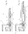
- FIG. 7a to 7f the individual steps of the method according to the invention for loading the transport vehicle will be described. So shows Fig. 7a a transport vehicle 10 in a state in which the central axis 22 and the rear axle 24 have a minimum possible distance 36 to each other (see, for example Fig. 1 ).
- the telekopierbare frame portion 34 and the telekopierbare support portion 38 are not extended. This condition is ideal, for example, for getting to a job site.
- the telekopierbare frame portion 34 and the telekopierbare support portion 38 can first be extended so that both the distance 52 between the central axis 22 and the rear axle 24 can increase, as well as the Support surface 26 of the transport area 18. This state is in the transport vehicle 10 of Fig. 7b shown.
- the reference numerals 34 'and 38' symbolize the extension of the telekopierbaren frame portion 34 and the telekopierbaren support portion 38.
- the telekopierbare frame portion 34 and the telekopierbare support portion 38 may be coupled together so that an extension of the two sections 34 and 38 can be carried out simultaneously and automatically.
- Fig. 7c is shown by extending (see 44 ') of the lifting cylinder 44 of the support frame 42, and thus the support surface 26 is raised so that it is at an intended angle ⁇ to the chassis 16 of the transport vehicle 10.
- the support surface 26 can be pushed backwards on the support frame 42 due to the displaceable mounting (compare 26 '), so that the support surface 26 approaches the bottom 32 and a passable loading ramp 40 is formed.
- the sequence of steps from the Fig. 7c and 7d can optionally be swapped. Motor vehicles 12 can then be driven or moved onto the support surface via the loading ramp 40 (see FIG Fig. 7e shows.
- the bearing surface 26 of the transport region 18 is to be returned to the horizontal starting position by retraction of the lifting cylinder 44.
- the bearing surface 26 can then be moved back on the support frame 42 to the original storage position via the displaceable mounting, as in FIG Arrow 26 "clarifies. After completing the step of Fig. 7e can the motor vehicle 12 be transported away.
Abstract
Mit der Erfindung wird ein Transportfahrzeug (10) zur Beförderung von rollbaren Gütern oder Fahrzeugen, insbesondere von Kraftfahrzeugen (12), Personenkraftwagen o.dgl., mit mindestens drei an einem Fahrgestell eines Zugfahrzeugs angeordneten Achsen (20, 22, 24) offenbart. Das Transportfahrzeug (10) weist ein frontseitig oberhalb einer lenkbaren Vorderachse (20) angeordnetes Führerhaus (14) sowie einen zumindest teilweise dem Fahrgestell (16) des Transportfahrzeugs (10) zugeordneten Transportbereich (18) auf. Der Transportbereich (18) umfasst eine Aufnahmefläche (26) zum Transport eines zu transportierenden Fahrzeugs, bspw. eines Kraftfahrzeugs (12). Dem Transportbereich (18) ist heckseitig wenigstens eine Hinterachse (24) zur Lastabstützung zugeordnet. Außerdem ist das Transportfahrzeug (10) mit einer Mittelachse (22) ausgestattet. Das Fahrgestell (16) des Transportfahrzeugs (10) weist außerdem Verstellmittel (34) für eine Veränderung der Distanz (36) zwischen der Mittelachse (22) und der Hinterachse (24) auf.The invention discloses a transport vehicle (10) for transporting rolling goods or vehicles, in particular motor vehicles (12), passenger vehicles or the like, having at least three axles (20, 22, 24) arranged on a chassis of a towing vehicle. The transport vehicle (10) has a driver's cab (14) arranged at the front above a steerable front axle (20) and a transport region (18) which is at least partially associated with the chassis (16) of the transport vehicle (10). The transport area (18) comprises a receiving surface (26) for transporting a vehicle to be transported, for example a motor vehicle (12). At least one rear axle (24) for load support is assigned to the transport area (18) on the rear side. In addition, the transport vehicle (10) is equipped with a central axis (22). The chassis (16) of the transport vehicle (10) also has adjusting means (34) for changing the distance (36) between the central axis (22) and the rear axle (24).
Description
Die vorliegende Erfindung betrifft ein Transportfahrzeug zur Beförderung von rollbaren Gütern oder Fahrzeugen, insbesondere von Kraftfahrzeugen, Personenkraftwagen o.dgl., gemäß den Merkmalen des unabhängigen Anspruches 1. Die Erfindung betrifft zudem ein Verfahren zum Beladen eines solchen Transportfahrzeuges mit den Merkmalen des unabhängigen Verfahrensanspruchs 14.The present invention relates to a transport vehicle for transporting rolling goods or vehicles, in particular motor vehicles, passenger cars or the like, according to the features of independent claim 1. The invention also relates to a method for loading such a transport vehicle having the features of
Transportfahrzeuge, die für den Transport einzelner oder mehrerer Personenkraftfahrzeuge vorgesehen und geeignet sind, sind in unterschiedlichen Ausführungsvarianten bekannt und werden meist pauschal als Autotransporter bezeichnet. Eine typische Variante solcher Transportfahrzeuge weist zwei oder drei Achsen, ein frontseitig oberhalb einer lenkbaren Vorderachse angeordnetes Führerhaus sowie einen dahinter angeordneten Transportbereich mit einer Plattform zur Aufnahme mindestens eines Fahrzeuges auf. Für einen Transport von einem Kraftfahrzeug oder auch von zwei Kraftfahrzeugen werden meist Transportfahrzeuge genutzt, welche speziell für einen Transport von einem Fahrzeug oder von zwei Kraftfahrzeugen ausgelegt sind. Insbesondere für die Bergung und den Transport von Unfallfahrzeugen, welche bspw. auf Schnellstraßen, Autobahnen oder sonstigen Straßen verunglückt sind, werden derartige kleinere Autotransporter mit geringer Ladekapazität eingesetzt, um in beengten Verkehrssituationen einfacher und schneller zur Unfallstelle gelangen zu können, bzw. um einen zügigen Abtransport der Unfallfahrzeuge zu ermöglichen.Transport vehicles, which are provided and suitable for the transport of individual or multiple passenger vehicles, are known in different design variants and are generally referred to as a car transporter. A typical variant of such transport vehicles has two or three axles, a driver's cab arranged at the front above a steerable front axle and a transport area arranged behind it with a platform for accommodating at least one vehicle. For a transport of a motor vehicle or two vehicles usually transport vehicles are used, which are designed specifically for transport of a vehicle or two vehicles. In particular, for the recovery and transport of accident vehicles, which are, for example, on motorways, highways or other roads crashed, such smaller car transporter are used with low loading capacity to get easier and faster in cramped traffic situations to the accident site, or a swift To allow removal of the accident vehicles.
Es sind bereits Transportfahrzeuge bekannt, bei welchen die Auflagefläche des Transportbereichs teleskopisch vergrößert und/oder ausgeschwenkt werden kann, um eine Laderampe zur Beladung des Transportfahrzeugs zu erschaffen. Die Auflagefläche kann dabei in einer Weise erweitert werden, dass auch Fahrzeuge mit einer geringen Bodenfreiheit auf das Transportfahrzeug befördert werden können. Ein derartiges Transportfahrzeug wird bspw. durch die
Weiterhin sind Transportfahrzeuge bekannt, welche zur Aufnahme eines Kraftfahrzeugs auf einer Transportfläche geeignet sind, und zusätzlich eine Transporteinrichtung umfassen, mittels welcher ein weiteres Fahrzeug zum Abtransport am Heck des Transportfahrzeugs angebunden werden kann, wie dies etwa in der
Aus Folge eines Unfalls mit zwei oder mehreren Fahrzeugen resultieren oftmals mehr oder weniger beschädigte und damit meist nicht mehr fahrbereite Fahrzeuge. Ein Fahrzeug, welches nur geringere Beschädigungen aufweist, kann oftmals trotz des Schadens weiterhin rangierfähig sein, so dass ein Abtransport auf der Auflagefläche eines Fahrzeugtransporters nicht zwingend notwendig ist. In solchen Fällen kann das Unfallfahrzeug an einer Transporteinrichtung am Heck des Transportfahrzeugs angebunden werden, um es hinter dem Transportfahrzeug nachziehen zu können. Ein weiteres Unfallfahrzeug, welches möglicherweise größere Schäden aufweist, die zu einer Rangierunfähigkeit des Unfallfahrzeugs führen, kann bspw. auf der Auflagefläche des Fahrzeugtransporters abtransportiert werden. Zur Positionierung eines bewegungsuntüchtigen Unfallfahrzeugs ist es oftmals vorteilhaft, wenn der Fahrzeugtransporter über einen integrierten Bergekran verfügt, was dazu führt, dass zur Umsetzung des Unfallfahrzeugs von der Unfallstelle auf den Fahrzeugtransporter kein zusätzliches Bergefahrzeug benötigt wird.As a result of an accident with two or more vehicles often result in more or less damaged and thus usually no longer roadworthy vehicles. A vehicle, which has only minor damage, can often still be rangeable despite the damage, so that a removal on the support surface of a vehicle transporter is not absolutely necessary. In such cases, the accident vehicle can be connected to a transport device at the rear of the transport vehicle in order to be able to follow behind the transport vehicle. Another accident vehicle, which may have greater damage, leading to a Rangierunfähigkeit the accident vehicle can, for example, be transported to the support surface of the vehicle transporter. For positioning a motionless accident vehicle, it is often advantageous if the vehicle transporter has an integrated crane mountains, which means that no additional recovery vehicle is needed to implement the accident vehicle from the scene of the accident on the vehicle transporter.
In solchen Fällen allerdings, bei welchen aus einer Unfallsituation zwei Unfallfahrzeuge resultieren, die nach dem Unfall rangierunfähig sind, kann ein Fahrzeugtransporter, welcher lediglich über eine Ladefläche zum Transport eines Fahrzeugs verfügt, oder im gegebenen Fall nur eine zusätzliche heckseitige Abschleppvorrichtung umfasst, die beiden rangierunfähigen Kraftfahrzeuge nicht alleine abtransportieren. Es muss ein zusätzliches Transportfahrzeug angefordert werden, wodurch sich die Zeitspanne bis zu einer kompletten Räumung der Unfallstelle und die erwünschte Wiederfreigabe der Straße/Fahrbahn verlängert, da wiederum Anforderungs-, Anfahrts- und Positionierungszeiten für das zweite Transportfahrzeug anfallen.In such cases, however, in which result from an accident situation two accident vehicles that are rangierunfähig after the accident, a vehicle transporter, which only has a cargo area for transporting a vehicle, or in the given case only includes an additional rear towing device, the two rangierunfähigen Do not transport motor vehicles alone. It must be requested an additional transport vehicle, which extends the time to complete clearance of the accident site and the desired re-release of the road / lane, as in turn arise request, arrival and positioning times for the second transport vehicle.
Auch der Einsatz eines Fahrzeugtransporters, welcher über eine Ladefläche zum Transport zweier Unfallfahrzeuge verfügt, bereitet oftmals Schwierigkeiten. Derartige Transportfahrzeuge sind gewöhnlich sehr unflexibel, besitzen einen großen Wendekreis und benötigen viel Platz, um rangieren zu können. Da in vielen Fällen die Autobahn oder eine sonstige Straße nach einem Unfall beengte Zustände aufweist, oder auch ein dichter Stau aufgrund nachfolgender weiterer Fahrzeuge entsteht, welcher die Anfahrt des Fahrzeugtransporters behindert, ist ein derartiges Transportfahrzeug oftmals nicht sinnvoll einsetzbar.The use of a vehicle transporter, which has a loading area for the transport of two accident vehicles, often causes difficulties. Such transport vehicles are usually very inflexible, have a large turning circle and need a lot of space to be able to rank. Since in many cases, the highway or other road after an accident has cramped conditions, or even a dense congestion due to subsequent other vehicles arises, which hinders the approach of the vehicle transporter, such a transport vehicle is often not useful.
Das vorrangige Ziel der vorliegenden Erfindung wird daher darin gesehen, ein Transportfahrzeug für rollbare Güter oder Fahrzeuge, insbesondere Kraftfahrzeuge, Personenkraftwagen o.dgl., zur Verfügung zu stellen, welches eine flexible Ladekapazität für ein bis zwei Kraftfahrzeuge aufweist, welche rangierunfähig oder auch fahrtüchtig sein können, dabei aber bestimmte Maximalabmessungen und Gesamtgewichte nicht überschreitet. Weiterhin soll das Transportfahrzeug eine einfache Rangierbarkeit aufweisen und einen engen Wendekreis besitzen, wodurch ein flexibler Einsatz des Transportfahrzeugs ermöglicht werden soll.The primary object of the present invention is therefore to provide a transport vehicle for rolling stock or vehicles, in particular motor vehicles, passenger cars or the like., Which has a flexible loading capacity for one to two motor vehicles, which are rangierunfähig or also roadworthy but can not exceed certain maximum dimensions and overall weights. Furthermore, the transport vehicle should have easy maneuverability and have a tight turning circle, whereby a flexible use of the transport vehicle should be made possible.
Die genannten Ziele der Erfindung werden mit dem Gegenstand des unabhängigen Anspruchs erreicht. Merkmale vorteilhafter Ausgestaltungen und Weiterbildungen der Erfindung werden durch die Unteransprüche beschrieben und finden sich in der nachfolgenden Beschreibung sowie den zugehörigen Zeichnungen.The stated objects of the invention are achieved with the subject matter of the independent claim. Features of advantageous embodiments and modifications of the invention are described by the subclaims and can be found in the following description and the accompanying drawings.
Die Erfindung schlägt zur Erreichung des genannten Ziels ein Transportfahrzeug zur Beförderung von rollbaren Gütern oder Fahrzeugen, insbesondere von Kraftfahrzeugen, Personenkraftwagen o.dgl., mit mindestens drei an einem Fahrgestell eines Zugfahrzeugs angeordneten Achsen mit den Merkmalen des unabhängigen Anspruchs 1 vor. Das erfindungsgemäße Transportfahrzeug weist ein frontseitig oberhalb einer lenkbaren Vorderachse angeordnetes Führerhaus sowie einen zumindest teilweise auf dem Fahrgestell des Transportfahrzeugs üblicherweise starr angeordneten Transportbereich auf. Der Transportbereich umfasst eine Aufnahmefläche zum Transport eines zu transportierenden Fahrzeugs, bspw. eines Kraftfahrzeugs. Dem Transportbereich ist heckseitig wenigstens eine Hinterachse zur Lastabstützung zugeordnet. Außerdem ist das Transportfahrzeug mit einer vorzugsweise angetriebenen Mittelachse ausgestattet. Üblicherweise weisen die Vorderachse und Mittelachse eine geringere Distanz auf als die Mittelachse und Hinterachse, um eine ideale Achslastverteilung in einem beladenen Zustand des Transportfahrzeugs zu erhalten. Das Fahrgestell des Transportfahrzeugs weist außerdem Verstellmittel für eine Veränderung der Distanz zwischen der Mittelachse und der Hinterachse auf.The invention proposes to achieve the above object, a transport vehicle for transporting rolling goods or vehicles, in particular of motor vehicles, passenger cars or the like, with at least three arranged on a chassis of a towing vehicle axles with the features of independent claim 1 before. The transport vehicle according to the invention has a driver's cab arranged at the front above a steerable front axle as well as a transport area which is usually rigidly arranged at least partially on the chassis of the transport vehicle. The transport area comprises a receiving area for transporting a vehicle to be transported, for example a motor vehicle. At the rear, at least one rear axle for load support is assigned to the transport area. In addition, the transport vehicle is equipped with a preferably driven central axis. Typically, the front and center axles are spaced closer than the center and rear axles to provide an ideal axle load distribution in a loaded condition of the transport vehicle. The chassis of the transport vehicle also has adjustment means for changing the distance between the center axis and the rear axle.
Bei dem Verstellmittel zur Veränderung der Distanz zwischen der Mittelachse und der Hinterachse kann es sich bspw. um ein teleskopierbares Verstellmittel handeln. Vorzugsweise sind zur Verstellung teleskopierbare Rahmenabschnitte des Transpostfahrzeugs vorgesehen. Durch eine teleskopierbare Ausgestaltung können die Verstellmittel zur Verstellung des Fahrgestells relativ kompakt und platzsparend aufgebaut werden. Denkbar ist auch eine Verwendung von übereinander schiebbaren Verstellmitteln. In einem komplett zusammengeschobenen Zustand der Verstellmittel des Fahrgestells weisen die Mittelachse und Hinterachse eine minimale Distanz zueinander auf. In diesem Fall ist das Transportfahrzeug zur Aufnahme von lediglich einem Kraftfahrzeug in der Lage. In einem komplett auseinandergeschobenen Zustand der Verstellmittel des Fahrgestells weisen die Mittelachse und Hinterachse eine maximale Distanz zueinander auf. Weiterhin können die Mittelachse und die Hinterachse auch auf eine mittlere Distanz zueinander eingestellt werden. Einhergehend mit einer Verstellung der Distanz zwischen der Mittelachse und Hinterachse kann eine Verstellung der Auflagefläche des Transportbereichs vorgenommen werden. Die Verstellung der Auflagefläche des Transportbereichs erfolgt bspw. ebenfalls mittels teleskopierbarer Verstellmittel. Weiterhin ist denkbar, die Auflagefläche aus mehreren übereinander verschiebbaren Einzelplatten auszubilden, um eine Verstellbarkeit der Auflagefläche zu realisieren. Die auf dem Fahrgestell angeordnete Auflagefläche kann in einem komplett zusammengeschobenen Zustand eine minimale Auflagefläche zur Aufnahme eines einzelnen Kraftfahrzeuges bilden. Bei einer Einstellung einer maximalen Größe der Auflagefläche können bis zu zwei Kraftfahrzeuge transportiert werden. Die Auflagefläche kann auch auf eine mittlere Größe eingestellt werden, um bspw. die Aufnahme eines großen Kraftfahrzeugs oder eines kleinen Tansportbusses zu ermöglichen. Üblicherweise umfasst das Transportfahrzeug in einem komplett auseinandergeschobenen Zustand des Fahrgestells bzw. der Auflagefläche eine maximale Länge von bis zu 10 Metern oder mehr, wodurch bereits mit Besitz der europäischen Fahrerlaubnisklasse C1, bzw. der ehemaligen Klasse 3 der deutschen Regelung bis zum Jahr 1998, eine Fahrerlaubnis für ein derartiges Transportfahrzeug vorliegt. Das Transportfahrzeug kann auch eine maximale Länge von mehr als 12 Metern aufweisen. In diesem Fall ist allerdings eine höhere Fahrerlaubnisklasse für eine Fahrerlaubnis des Transportfahrzeugs notwendig.The adjusting means for changing the distance between the central axis and the rear axle may, for example, be a telescopic adjusting means. Preferably, telescopic frame sections of the trans-post vehicle are provided for adjustment. By a telescopic design, the adjusting means for adjusting the chassis can be constructed relatively compact and space-saving. It is also conceivable use of superimposed Adjusting means. In a completely collapsed state of the adjustment of the chassis, the central axis and rear axle at a minimum distance from each other. In this case, the transport vehicle is capable of accommodating only a motor vehicle. In a completely disengaged state of the adjustment means of the chassis, the central axis and rear axle at a maximum distance from each other. Furthermore, the central axis and the rear axle can also be adjusted to a mean distance from each other. Along with an adjustment of the distance between the central axis and the rear axle, an adjustment of the support surface of the transport area can be made. The adjustment of the support surface of the transport area is carried out, for example, also by means of telescoping adjustment means. Furthermore, it is conceivable to form the support surface of a plurality of individual plates which can be displaced one above the other in order to realize an adjustability of the support surface. The arranged on the chassis support surface can form a minimum support surface for receiving a single motor vehicle in a fully collapsed state. When setting a maximum size of the support surface up to two vehicles can be transported. The support surface can also be set to a medium size, for example, to allow the inclusion of a large motor vehicle or a small Tanzsportbusses. Usually, the transport vehicle in a completely pushed apart condition of the chassis or the support surface a maximum length of up to 10 meters or more, which already possesses the European driving license class C1, or the former class 3 of the German regulation until 1998, a Driving license for such a transport vehicle is present. The transport vehicle may also have a maximum length of more than 12 meters. In this case, however, a higher driving license class for a license of the transport vehicle is necessary.
Die Verstellung der Auflagefläche des Transportbereichs kann an eine Verstellung der Distanz zwischen der Mittelachse und der Hinterachse mittels der teleskopischen Verstellmittel, insbesondere mittels der teleskopierbaren Rahmenabschnitte, gekoppelt sein. Auf diese Weise ist bei einer Koppelung des Verstellmittels des Fahrgestells mit dem Verstellmittel der Auflagefläche des Transportbereichs die Fläche der Auflagefläche automatisch und einhergehend mit der Verstellung des Fahrgestells einstellbar. Neben einer automatischen Anpassung der Auflagefläche ist auch denkbar, eine unabhängige und manuelle Verstellung zu ermöglichen. Eine manuelle Verstellung kann bspw. in einem Fall vorteilhaft sein, in welchem eine Veränderung der Distanz zwischen der Mittelachse und der Hinterachse nicht notwendig ist, aber die Größe des Transportbereichs zur Beladung des Transportfahrzeugs mit einem größeren Kraftfahrzeug noch nicht ausreicht.The adjustment of the bearing surface of the transport region can be coupled to an adjustment of the distance between the central axis and the rear axle by means of the telescopic adjusting means, in particular by means of the telescopic frame sections. In this way, with a coupling of the adjusting means of the chassis with the adjusting means of the support surface of the transport area, the surface of the support surface automatically and in accordance with the adjustment of the chassis adjustable. In addition to an automatic adjustment of the support surface is also conceivable to allow an independent and manual adjustment. For example, manual adjustment may be advantageous in a case where there is a change in the distance between the central axis and the rear axle is not necessary, but the size of the transport area for loading the transport vehicle with a larger motor vehicle is not sufficient.
Weiterhin ist denkbar, die Auflagefläche des Transportbereichs gegenüber dem Fahrgestell verstellbar und/oder verschiebbar und/oder verschwenkbar auszubilden. Hierbei besteht die Möglichkeit, die Auflagefläche des Transportbereichs derartig zu verstellen und/oder zu verschieben und/oder zu verschwenken, dass eine Laderampe zur Befahrung des Transportbereichs entsteht, um den Transportbereich des Transportfahrzeugs mit fahrtauglichen Kraftfahrzeugen beladen zu können. Zu diesem Zweck kann die Auflagefläche des Transportbereichs verschiebbar auf einem Tragrahmen angeordnet sein, welcher über eine Schwenkachse an dem Fahrgestell befestigt ist. Mit Hilfe des Tragrahmens kann die Auflagefläche derartig nach hinten verschoben bzw. nach oben verschwenkt werden, sodass Heckseitig am Transportfahrzeug eine befahrbare Laderampe entsteht. Um den Neigungswinkel zwischen der Laderampe und der Straße oder dem Boden zu verändern, kann die Auflagefläche derartig vergrößert bzw. verschwenkt werden, dass sich der Neigungswinkel der Laderampe verringert und die Laderampe auch für Kraftfahrzeuge mit niedriger Bodenfreiheit befahrbar ist.Furthermore, it is conceivable that the bearing surface of the transport region relative to the chassis adjustable and / or displaceable and / or pivotally form. In this case, it is possible to adjust the support surface of the transport area in such a way and / or to move and / or pivot that a loading ramp for driving the transport area is created in order to load the transport area of the transport vehicle with roadworthy motor vehicles. For this purpose, the support surface of the transport region can be arranged displaceably on a support frame, which is attached via a pivot axis to the chassis. With the help of the support frame, the support surface can be moved backwards or pivoted upwards so that the rear side of the transport vehicle, a passable loading ramp is created. In order to change the angle of inclination between the loading ramp and the road or the ground, the support surface can be increased or pivoted such that the inclination angle of the loading ramp is reduced and the loading ramp is also passable for motor vehicles with low ground clearance.
Für eine Beladung des Transportfahrzeugs mit einem Kraftfahrzeug kann das Transportfahrzeug erfindungsgemäß zudem einen Bergekran umfassen. Üblicherweise umfassen erfindungsgemäße Transportfahrzeuge, welche eine Zulassung von bis zu 7,5 Tonnen aufweisen, einen Bergekran. Für Transportfahrzeuge, die bspw. lediglich eine Zulassung von bis zu 3,5 Tonnen besitzen, ist auch ein Verzicht auf einen Bergekran denkbar. Der Bergekran weist für gewöhnlich ein großes Gewicht auf, wodurch sich das Gewicht der zulässigen Beladung einschränkt. Mittels des Bergekrans können insbesondere rangierunfähige Kraftfahrzeuge auf den Transportbereich des Transportfahrzeugs gehoben werden.For a loading of the transport vehicle with a motor vehicle, the transport vehicle according to the invention may also comprise a crane mountains. Usually transport vehicles according to the invention, which have an approval of up to 7.5 tons, include a crane. For transport vehicles, which have, for example, only an approval of up to 3.5 tons, a waiver of a rescue crane is conceivable. The crane usually has a large weight, which limits the weight of the permitted load. By means of the cranes crane, in particular, unfoldable motor vehicles can be lifted onto the transport area of the transport vehicle.
Vorteilhaft an einer derartigen Ausgestaltung eines Transportfahrzeugs ist die situationsbedingte Verstellbarkeit der Fahrzeuglänge bzw. der Distanz zwischen der Mittelachse und der Hinterachse, sowie der Größe des Transportbereichs. Da insbesondere bei Unglücksfällen auf Autobahnen oder sonstigen Straßen, bspw. mit zwei oder mehr verunglückten Kraftfahrzeugen, aufgrund von sich zurückstauenden folgenden Fahrzeugen ein beengter Anfahrtsbereich entsteht und oftmals beengte und eingeschränkte Rangiermöglichkeiten an der Unfallstelle auftreten, kann das Transportfahrzeug für die Anfahrt oder das Rangieren an der Unfallstelle in einem auf eine minimale Fahrzeuglänge zusammengeschobenen Zustand bewegt werden. An der Unfallstelle kann das Transportfahrzeug an die Gegebenheiten der verunglückten Kraftfahrzeuge angepasst werden. Innerhalb kurzer Zeit ist das Fahrgestell bzw. die Auflagefläche des Transportfahrzeugs derartig einstellbar, dass eine Beladung des Transportbereichs mit zwei Kraftfahrzeugen ermöglicht werden kann. Das Fahrgestell bzw. die Auflagefläche kann dabei auf eine maximale Länge bzw. Fläche oder auf ein Mittelmaß auseinander geschoben werden. Durch die Transport- bzw. Belademöglichkeit von bis zu zwei Kraftfahrzeugen kann eine zügige Räumung der Autobahn ermöglicht werden, um die Straße schnell für den nachfolgenden Verkehr frei geben zu können.An advantage of such a configuration of a transport vehicle is the situation-dependent adjustability of the vehicle length or the distance between the central axis and the rear axle, as well as the size of the transport area. Since, in particular in accidents on motorways or other roads, for example. With two or more crashed vehicles, due to backward following vehicles a cramped approach area arises and often cramped and limited maneuvering opportunities occur at the scene, the transport vehicle for the approach or maneuvering the accident site are moved in a pushed together to a minimum vehicle length state. At the Accident site, the transport vehicle can be adapted to the circumstances of the accident motor vehicles. Within a short time, the chassis or the support surface of the transport vehicle is adjustable so that a loading of the transport area can be made possible with two vehicles. The chassis or the support surface can be pushed apart to a maximum length or area or to a mediocrity. By the transport or loading possibility of up to two vehicles, a speedy clearance of the highway can be made to give the road quickly for subsequent traffic free.
Erfindungsgemäß ist der Transportbereich starr mit dem Fahrgestell des Zugfahrzeugs verbunden. Der Antrieb des Transportfahrzeugs kann über die antreibbare Mittelachse erfolgen. Sinnvollerweise können die Reifen der angetriebenen Mittelachse, welche typischerweise als Starrachse mit Mitteldifferenzial ausgebildet ist, sowie die Reifen der Hinterachse einen kleineren Durchmesser als die Reifen der Vorderachse besitzen, um die Transporthöhe des Transportfahrzeugs möglichst niedrig zu halten. Die Hinterachse des Transportfahrzeugs kann ebenfalls als Starrachse ausgebildet sein. Eine Ausgestaltung der Hinterachse als eine Zwillingsachse ist ebenfalls denkbar, wodurch der Einsatz kleinerer Reifen vereinfacht wird. Zudem kann aufgrund der Zwillingsachse eine höhere Achslast ermöglicht werden. Statt einer Zwillingsachse kann auch eine Doppelachse vorhanden sein. Weiterhin ergibt sich eine größere Fahrstabilität des Transportfahrzeugs, was insbesondere bei einem beladenen Transportfahrzeug vorteilhaft ist.According to the invention, the transport area is rigidly connected to the chassis of the towing vehicle. The drive of the transport vehicle can be done via the drivable central axis. It is expedient that the tires of the driven central axis, which is typically designed as a center-differential rigid axle, and the tires of the rear axle may have a smaller diameter than the tires of the front axle, in order to keep the transporting height of the transport vehicle as low as possible. The rear axle of the transport vehicle can also be designed as a rigid axle. An embodiment of the rear axle as a twin axle is also conceivable, whereby the use of smaller tires is simplified. In addition, a higher axle load can be made possible due to the twin axle. Instead of a twin axis, a double axis can also be present. Furthermore, there is a greater driving stability of the transport vehicle, which is particularly advantageous for a loaded transport vehicle.
Idealerweise kann es sich bei der Hinterachse auch um eine lenkbare Achse handeln. Eine derartig lenkbare Hinterachse kann wahlweise eine aktive Lenkung aufweisen, die mit der lenkbaren Vorderachse in einer Weise gekoppelt ist, dass ein gegensinniger Lenkeinschlag gegeben ist, mit dessen Hilfe eine effektive Reduzierung des Wendekreises des Transportfahrzeugs und eine einfache Rangierfähigkeit des Transportfahrzeugs realisiert werden kann. Es ist leicht ersichtlich, dass eine gegensinnige Lenkung der Hinterräder zur Vermeidung von straken Verspannungen fast unverzichtbar ist, da die Hinterachse, zumindest bei einer maximalen Distanz zwischen der Mittelachse und der Hinterachse, relativ weit von der Mittelachse beabstandet ist. Bei einer nicht lenkbaren Mittelachse und einer ungelenkten Hinterachse würde eine Kurvenfahrt stark erschwert. Bei einer ungelenkten Hinterachse wäre eine gleichsinnig zur Vorderachse mitlenkende Mittelachse fast unverzichtbar, damit Kurvenfahrten ohne starke Materialbelastungen ermöglicht würden. Wahlweise kann die Hinterachse bspw. eine hydraulische oder elektromotorisch betriebene Lenkung aufweisen, die mit der gelenkten Vorderachse gekoppelt ist. Ebenso möglich ist jedoch auch eine passive Hinterachslenkung, die mittels einer geeigneten Achsgeometrie in einer Weise realisierbar ist, dass durch die bei der Kurvenfahrt auftretenden Querkräfte ein gegensinniger Lenkeinschlag der Hinterräder zu den gelenkten Vorderrädern erzeugt wird. Es ist auch denkbar, die Lenkbarkeit der Hinterachse an eine Mindestdistanz zwischen der Mittelachse und der Hinterachse zu koppeln, um je nach Betriebssituation eine geeignete Lenkung des Transportfahrzeugs zu ermöglichen.Ideally, the rear axle may also be a steerable axle. Such a steerable rear axle may optionally have an active steering, which is coupled to the steerable front axle in a manner that an opposite direction steering is given, with the help of an effective reduction of the turning circle of the transport vehicle and a simple maneuverability of the transport vehicle can be realized. It is readily apparent that opposing steering of the rear wheels to avoid strains is almost indispensable since the rear axle, at least at a maximum distance between the central axis and the rear axle, is relatively far from the central axis. With a non-steerable central axis and a steered rear axle cornering would be greatly complicated. In the case of an unguided rear axle, a central axis co-steering in the same direction as the front axle would be almost indispensable, so that cornering would be possible without heavy material loads. Optionally, the rear axle, for example. Have a hydraulic or electric motor operated steering, with the steered Front axle is coupled. However, also possible is a passive rear axle steering, which can be realized by means of a suitable axle geometry in a manner that is generated by the lateral forces occurring during cornering an opposing steering angle of the rear wheels to the steered front wheels. It is also conceivable to couple the steerability of the rear axle to a minimum distance between the central axle and the rear axle in order to allow suitable steering of the transport vehicle depending on the operating situation.
Weiterhin schlägt die vorliegende Erfindung zur Erreichung der oben genannten Ziele ein Verfahren zum Beladen eines Transportfahrzeugs mit den Merkmalen des unabhängigen Verfahrensanspruchs vor. Das Verfahren bezieht sich dabei auf ein Transportfahrzeug, welches zur Beförderung von rollbaren Gütern oder Fahrzeugen, insbesondere Kraftfahrzeugen, Personenkraftwagen oder dgl. vorgesehen ist. Das Transportfahrzeug weist mindestens drei an einem Fahrgestell angeordnete Achsen auf, ein frontseitig oberhalb einer lenkbaren Vorderachse angeordnetes Führerhaus sowie einem zumindest teilweise dem Fahrgestell zugeordneten Transportbereich mit einer Auflagefläche für die zu transportierenden rollbaren Güter oder Fahrzeuge. Das Fahrgestell weist Verstellmittel zur Verstellung einer Distanz zwischen einer Mittelachse des Transportfahrzeugs und wenigstens einer Hinterachse auf. Das erfindungsgemäße Beladeverfahren umfasst zumindest die nachfolgend genannten Schritte:
- Vergrößern der Distanz zwischen der Mittelachse und der wenigstens einen Hinterachse des Transportfahrzeugs mittels Ausfahren teleskopierbarer Verstellmittel des Fahrgestells,
- Vergrößern der Auflagefläche des Transportbereichs mittels Ausfahren teleskopierbarer Verstellmittel,
- Verschieben der Auflagefläche des Transportbereichs nach hinten sowie nach hinten Kippen der Auflagefläche zur Bildung einer Laderampe,
- Auffahren zu transportierender rollbarer Güter oder Fahrzeuge auf die Laderampe,
- Zurückschwenken der Auflagefläche des Transportbereichs in eine horizontale Ausgangsposition und Zurückbewegen der Auflagefläche in eine ursprüngliche Lagerposition.
- Increasing the distance between the central axis and the at least one rear axle of the transport vehicle by extending telescopic adjustment means of the chassis,
- Increase the contact surface of the transport area by extending telescopic adjustment means,
- Moving the support surface of the transport area to the rear and to the rear tilting the support surface to form a loading ramp,
- Ascending transportable rolling stock or vehicles onto the loading ramp,
- Swiveling back the bearing surface of the transport area in a horizontal starting position and moving back the bearing surface in an original storage position.
Weiterhin kann das genannte Verfahren eine Koppelung der Vergrößerung der Distanz zwischen der Mittelachse und der Hinterachse mittels der teleskopierbaren Verstellmittel und der Vergrößerung der Auflagefläche des Transportbereichs mittels teleskopierbarer Verstellmittel genutzt werden, sodass die Vergrößerung des Fahrgestells mit der Vergrößerung der Auflagefläche einhergeht.Furthermore, said method, a coupling of the increase in the distance between the central axis and the rear axle by means of the telescopic adjusting means and the increase of the support surface of the transport area can be used by means of telescoping adjustment means, so that the enlargement of the chassis is associated with the increase of the support surface.
Die im Zusammenhang mit dem erfindungsgemäßen Transportfahrzeug genannten Ausführungsvarianten des Transportfahrzeugs können selbstverständlich auch für das Transportfahrzeug des erfindungsgemäßen Beladeverfahrens gelten. Daher wird auf eine erneute Darlegung der Ausführungsformen verzichtet und auf die bereits beschriebenen Ausführungen verwiesen.The embodiments of the transport vehicle mentioned in connection with the transport vehicle according to the invention may of course also apply to the transport vehicle of the loading method according to the invention. Therefore, it is dispensed with a renewed presentation of the embodiments and referred to the embodiments already described.
Im Folgenden sollen Ausführungsbeispiele die Erfindung und ihre Vorteile anhand der beigefügten Figuren näher erläutern. Die Größenverhältnisse der einzelnen Elemente zueinander in den Figuren entsprechen nicht immer den realen Größenverhältnissen, da einige Formen vereinfacht und andere Formen zur besseren Veranschaulichung vergrößert im Verhältnis zu anderen Elementen dargestellt sind.
-
Fig. 1 zeigt eine schematische Seitenansicht einer Ausführungsvariante eines erfindungsgemäßen Transportfahrzeugs. -
Fig. 2 zeigt eine schematische Ansicht des eine Laderampe bildenden Transportfahrzeugs. -
Fig. 3 zeigt eine schematische Seitenansicht des beladenen Transportfahrzeugs mit Zwillingsachse. -
Fig. 4 zeigt eine schematische Ansicht des Transportfahrzeugs mit teleskopiertem Fahrgestell. -
Fig. 5 zeigt eine schematische Ansicht eines Transportfahrzeugs mit tiefer Ladeebene. -
Fig. 6 zeigt eine schematische Ansicht eines mit einem Kleintransporter beladenen Transportfahrzeugs. -
Fig. 7a bis 7f zeigen die einzelnen Schritte eines erfindungsgemäßen Beladeverfahrens.
-
Fig. 1 shows a schematic side view of an embodiment of a transport vehicle according to the invention. -
Fig. 2 shows a schematic view of a loading ramp forming a transport vehicle. -
Fig. 3 shows a schematic side view of the loaded transport vehicle with twin axis. -
Fig. 4 shows a schematic view of the transport vehicle with telescoped chassis. -
Fig. 5 shows a schematic view of a transport vehicle with low loading level. -
Fig. 6 shows a schematic view of a loaded with a vans transport vehicle. -
Fig. 7a to 7f show the individual steps of a loading method according to the invention.
Für gleiche oder gleich wirkende Elemente der Erfindung werden identische Bezugszeichen verwendet. Ferner werden der Übersicht halber nur Bezugszeichen in den einzelnen Figuren dargestellt, die für die Beschreibung der jeweiligen Figur erforderlich sind. Die dargestellten Ausführungsformen stellen lediglich Beispiele dar, wie die erfindungsgemäße Vorrichtung ausgestaltet sein kann und stellen keine abschließende Begrenzung dar.For identical or equivalent elements of the invention, identical reference numerals are used. Furthermore, for the sake of clarity, only reference symbols are shown in the individual figures, which are required for the description of the respective figure. The illustrated embodiments are only examples of how the device according to the invention can be designed and do not represent a final limitation.
Die
Idealerweise beträgt der Abstand 30 zwischen einer Unterseite des Fahrgestells 16 und dem Boden 32 und damit die Bodenfreiheit in diesem Bereich zwischen 250 und 300 Millimeter. Zur Vergrößerung der horizontalen Distanz zwischen der Mittelachse 22 und der Hinterachse 24 weist das Fahrgestell 16 im Bereich zwischen der Mittelachse 22 und der Hinterachse 24 einen telekopierbaren Rahmenabschnitt 34 auf. In der Darstellung der
In der weiteren schematischen Seitenansicht der
In der weiteren schematischen Seitenansicht der
Die schematische Seitenansicht der
Das in
In
Ergänzend zu erwähnen ist, dass alle Ausführungsvarianten des Transportfahrzeuges 10 gemäß den
Die teleskopierbaren Rahmenabschnitte 34 können bspw. mit Hilfe von linear verschiebbaren Rahmenabschnitten, denen hydraulische Verstellmittel o. dgl. zugeordnet sind, in der Länge verstellt werden, wobei sicherzustellen ist, dass der Rahmen 16 hierbei keinen Durchbiegungen oder Torsionen unterliegt, abgesehen von den erwünschten Elastizitäten, die für solche Fahrzeuge in Leiterrahmenbauweise zur Vermeidung von Materialbrüchen und unzulässig hohen Belastungen, insbesondere beim Überwinden größerer Bodenunebenheiten unverzichtbar sind.The
Durch die
Im folgenden Schritt, welcher in
Die Erfindung wurde unter Bezugnahme auf die in den
- 1010
- Transportfahrzeugtransport vehicle
- 1212
- fahrtüchtiges Kraftfahrzeugroadworthy motor vehicle
- 12'12 '
- rangierunfähiges Kraftfahrzeugmentally disabled motor vehicle
- 12"12 "
- Kraftfahrzeug, KleintransporterMotor vehicle, pickup truck
- 12*12 *
- Bewegen des Kraftfahrzeugs auf die AuflageflächeMoving the motor vehicle on the support surface
- 1414
- Führerhauscabin
- 1616
- Fahrgestellchassis
- 1818
- Transportbereichtransport sector
- 2020
- VorderachseFront
- 2222
- Mittelachsecentral axis
- 2424
- Hinterachserear axle
- 24',24"24 ', 24 "
- Zwillingsachsetwin axis
- 2626
- Auflageflächebearing surface
- 26'26 '
- Nach hinten Schieben der AuflageflächePush back the support surface
- 26"26 "
- Zurückschieben der AuflageflächePushing back the support surface
- 2828
- BergekranBergekran
- 3030
- Abstand zwischen Fahrgestellunterseite und Boden, BodenfreiheitDistance between underbody and ground, ground clearance
- 3232
- Bodenground
- 3434
- teleskopierbarer Rahmenabschnitttelescopic frame section
- 34'34 '
- Ausfahren des teleskopierbaren RahmenabschnittsExtending the telescopic frame section
- 3636
- minimale Distanz, Radstand, Achsabstandminimum distance, wheelbase, center distance
- 3838
- teleskopierbarer Auflageabschnitttelescopic support section
- 38'38 '
- Ausfahren des teleskopierbaren AuflageabschnittsExtending the telescopic support section
- 4040
- Laderampeloading ramp
- 4242
- Tragrahmensupporting frame
- 4444
- Hubzylinderlifting cylinder
- 44'44 '
- Ausfahren des HubzylindersExtension of the lifting cylinder
- 44"44 "
- Einfahren des HubzylindersRetraction of the lifting cylinder
- 4646
- Schwenkachseswivel axis
- 4848
- Bodenfreiheitground clearance
- 5050
- maximale Distanzmaximum distance
- 5252
- mittlere Distanzaverage distance
Claims (15)
Applications Claiming Priority (1)
| Application Number | Priority Date | Filing Date | Title |
|---|---|---|---|
| DE202015105169 | 2015-09-30 |
Publications (2)
| Publication Number | Publication Date |
|---|---|
| EP3150428A1 true EP3150428A1 (en) | 2017-04-05 |
| EP3150428B1 EP3150428B1 (en) | 2019-12-11 |
Family
ID=56943373
Family Applications (1)
| Application Number | Title | Priority Date | Filing Date |
|---|---|---|---|
| EP16189043.9A Active EP3150428B1 (en) | 2015-09-30 | 2016-09-15 | Transport vehicle for motor vehicles with variable transport surface and method for loading such a transport vehicle |
Country Status (1)
| Country | Link |
|---|---|
| EP (1) | EP3150428B1 (en) |
Cited By (1)
| Publication number | Priority date | Publication date | Assignee | Title |
|---|---|---|---|---|
| EP3851168A1 (en) * | 2020-01-20 | 2021-07-21 | Helmut Fliegl | Vehicle trailer for motor vehicles that have been in an accident |
Citations (8)
| Publication number | Priority date | Publication date | Assignee | Title |
|---|---|---|---|---|
| WO1987001341A1 (en) * | 1985-09-10 | 1987-03-12 | Per Lind | Arrangement for a recovery vehicle |
| US4795303A (en) | 1987-05-29 | 1989-01-03 | Vulcan Equipment Company | Vehicle transporting apparatus |
| DE68905892T2 (en) | 1988-09-28 | 1993-10-14 | Jige Lohr Wreckers Sa | Vehicle transporter with a telescopic loading area. |
| US6402459B1 (en) | 1998-03-13 | 2002-06-11 | Mikael Pauli | Device comprising an elongated tubular body arranged to be located in water |
| GB2463897A (en) * | 2008-09-27 | 2010-03-31 | Geoffrey Spence | Extendible truck |
| WO2012071885A1 (en) * | 2010-12-02 | 2012-06-07 | 湖南三一智能控制设备有限公司 | Engineering vehicle and chassis thereof |
| US20130149084A1 (en) * | 2008-05-30 | 2013-06-13 | Miller Industries Towing Equipment Inc. | Low center of gravity carrier |
| EP2689957A1 (en) * | 2012-07-24 | 2014-01-29 | Francesco Luciano Tebaldi | Trailer |
-
2016
- 2016-09-15 EP EP16189043.9A patent/EP3150428B1/en active Active
Patent Citations (8)
| Publication number | Priority date | Publication date | Assignee | Title |
|---|---|---|---|---|
| WO1987001341A1 (en) * | 1985-09-10 | 1987-03-12 | Per Lind | Arrangement for a recovery vehicle |
| US4795303A (en) | 1987-05-29 | 1989-01-03 | Vulcan Equipment Company | Vehicle transporting apparatus |
| DE68905892T2 (en) | 1988-09-28 | 1993-10-14 | Jige Lohr Wreckers Sa | Vehicle transporter with a telescopic loading area. |
| US6402459B1 (en) | 1998-03-13 | 2002-06-11 | Mikael Pauli | Device comprising an elongated tubular body arranged to be located in water |
| US20130149084A1 (en) * | 2008-05-30 | 2013-06-13 | Miller Industries Towing Equipment Inc. | Low center of gravity carrier |
| GB2463897A (en) * | 2008-09-27 | 2010-03-31 | Geoffrey Spence | Extendible truck |
| WO2012071885A1 (en) * | 2010-12-02 | 2012-06-07 | 湖南三一智能控制设备有限公司 | Engineering vehicle and chassis thereof |
| EP2689957A1 (en) * | 2012-07-24 | 2014-01-29 | Francesco Luciano Tebaldi | Trailer |
Cited By (1)
| Publication number | Priority date | Publication date | Assignee | Title |
|---|---|---|---|---|
| EP3851168A1 (en) * | 2020-01-20 | 2021-07-21 | Helmut Fliegl | Vehicle trailer for motor vehicles that have been in an accident |
Also Published As
| Publication number | Publication date |
|---|---|
| EP3150428B1 (en) | 2019-12-11 |
Similar Documents
| Publication | Publication Date | Title |
|---|---|---|
| EP1661756B1 (en) | Cars transporting vehicle and such a vehicle combined with a trailer | |
| DE202012010545U1 (en) | Heavy-duty transport vehicle for transporting an elongate object | |
| DE202018106492U1 (en) | Vehicle for transporting a long cargo | |
| EP2917070B1 (en) | Heavy-load transport vehicle for transporting an elongated object | |
| EP1486375B1 (en) | Length-adjustable container-chassis | |
| DE102012021613B4 (en) | Heavy-duty transport vehicle for transporting an elongate object | |
| WO2004041621A1 (en) | Device and method for moving a motor vehicle sideways | |
| EP3326892A1 (en) | Transport trailer with running gear and at least one floor platform | |
| EP3150428B1 (en) | Transport vehicle for motor vehicles with variable transport surface and method for loading such a transport vehicle | |
| EP1927505A2 (en) | Truck for transporting vehicle, towing vehicle and trailer therefor and method for loading the trailer | |
| EP1122151B1 (en) | Vehicle with low-level extensible loading platform | |
| DE3405259C2 (en) | Road low loaders, in particular low loader trailers for tractor units | |
| EP3293048B1 (en) | Loading platform | |
| DE2423322B2 (en) | RAILWAY GOODS FOR THE TRANSPORT OF VEHICLES, CARAVANS AND BOATS | |
| DE3332227C2 (en) | Bridge viewing device | |
| EP3927563B1 (en) | Device for lowering and raising the rear-side part of the chassis of a vehicle | |
| DE102010046084B4 (en) | Commercial vehicle for transporting containers | |
| DE10223612C1 (en) | Tractor vehicle for articulated lorry has saddle plate for hitch arm actuated by lifting jack | |
| EP3098142A1 (en) | Low-loader for transporting circular ring segment shaped loads | |
| DE102012108527B4 (en) | Truck with a protective frame | |
| EP2878485B1 (en) | Transport vehicle for motor vehicles and method for loading them | |
| EP2878484B1 (en) | Transport vehicle for motor vehicles and method for loading them | |
| DE3144164A1 (en) | Wheel support trolley | |
| DE202013105403U1 (en) | Transport vehicle for motor vehicles | |
| EP3785988B1 (en) | Vehicle transporter |
Legal Events
| Date | Code | Title | Description |
|---|---|---|---|
| PUAI | Public reference made under article 153(3) epc to a published international application that has entered the european phase |
Free format text: ORIGINAL CODE: 0009012 |
|
| STAA | Information on the status of an ep patent application or granted ep patent |
Free format text: STATUS: THE APPLICATION HAS BEEN PUBLISHED |
|
| AK | Designated contracting states |
Kind code of ref document: A1 Designated state(s): AL AT BE BG CH CY CZ DE DK EE ES FI FR GB GR HR HU IE IS IT LI LT LU LV MC MK MT NL NO PL PT RO RS SE SI SK SM TR |
|
| AX | Request for extension of the european patent |
Extension state: BA ME |
|
| STAA | Information on the status of an ep patent application or granted ep patent |
Free format text: STATUS: REQUEST FOR EXAMINATION WAS MADE |
|
| 17P | Request for examination filed |
Effective date: 20171005 |
|
| RBV | Designated contracting states (corrected) |
Designated state(s): AL AT BE BG CH CY CZ DE DK EE ES FI FR GB GR HR HU IE IS IT LI LT LU LV MC MK MT NL NO PL PT RO RS SE SI SK SM TR |
|
| GRAP | Despatch of communication of intention to grant a patent |
Free format text: ORIGINAL CODE: EPIDOSNIGR1 |
|
| STAA | Information on the status of an ep patent application or granted ep patent |
Free format text: STATUS: GRANT OF PATENT IS INTENDED |
|
| INTG | Intention to grant announced |
Effective date: 20190423 |
|
| GRAS | Grant fee paid |
Free format text: ORIGINAL CODE: EPIDOSNIGR3 |
|
| GRAA | (expected) grant |
Free format text: ORIGINAL CODE: 0009210 |
|
| STAA | Information on the status of an ep patent application or granted ep patent |
Free format text: STATUS: THE PATENT HAS BEEN GRANTED |
|
| AK | Designated contracting states |
Kind code of ref document: B1 Designated state(s): AL AT BE BG CH CY CZ DE DK EE ES FI FR GB GR HR HU IE IS IT LI LT LU LV MC MK MT NL NO PL PT RO RS SE SI SK SM TR |
|
| REG | Reference to a national code |
Ref country code: GB Ref legal event code: FG4D Free format text: NOT ENGLISH |
|
| REG | Reference to a national code |
Ref country code: CH Ref legal event code: EP |
|
| REG | Reference to a national code |
Ref country code: AT Ref legal event code: REF Ref document number: 1211863 Country of ref document: AT Kind code of ref document: T Effective date: 20191215 |
|
| REG | Reference to a national code |
Ref country code: DE Ref legal event code: R096 Ref document number: 502016007957 Country of ref document: DE |
|
| REG | Reference to a national code |
Ref country code: IE Ref legal event code: FG4D Free format text: LANGUAGE OF EP DOCUMENT: GERMAN |
|
| REG | Reference to a national code |
Ref country code: NL Ref legal event code: MP Effective date: 20191211 |
|
| REG | Reference to a national code |
Ref country code: LT Ref legal event code: MG4D |
|
| PG25 | Lapsed in a contracting state [announced via postgrant information from national office to epo] |
Ref country code: LT Free format text: LAPSE BECAUSE OF FAILURE TO SUBMIT A TRANSLATION OF THE DESCRIPTION OR TO PAY THE FEE WITHIN THE PRESCRIBED TIME-LIMIT Effective date: 20191211 Ref country code: NO Free format text: LAPSE BECAUSE OF FAILURE TO SUBMIT A TRANSLATION OF THE DESCRIPTION OR TO PAY THE FEE WITHIN THE PRESCRIBED TIME-LIMIT Effective date: 20200311 Ref country code: LV Free format text: LAPSE BECAUSE OF FAILURE TO SUBMIT A TRANSLATION OF THE DESCRIPTION OR TO PAY THE FEE WITHIN THE PRESCRIBED TIME-LIMIT Effective date: 20191211 Ref country code: SE Free format text: LAPSE BECAUSE OF FAILURE TO SUBMIT A TRANSLATION OF THE DESCRIPTION OR TO PAY THE FEE WITHIN THE PRESCRIBED TIME-LIMIT Effective date: 20191211 Ref country code: GR Free format text: LAPSE BECAUSE OF FAILURE TO SUBMIT A TRANSLATION OF THE DESCRIPTION OR TO PAY THE FEE WITHIN THE PRESCRIBED TIME-LIMIT Effective date: 20200312 Ref country code: FI Free format text: LAPSE BECAUSE OF FAILURE TO SUBMIT A TRANSLATION OF THE DESCRIPTION OR TO PAY THE FEE WITHIN THE PRESCRIBED TIME-LIMIT Effective date: 20191211 Ref country code: BG Free format text: LAPSE BECAUSE OF FAILURE TO SUBMIT A TRANSLATION OF THE DESCRIPTION OR TO PAY THE FEE WITHIN THE PRESCRIBED TIME-LIMIT Effective date: 20200311 |
|
| PG25 | Lapsed in a contracting state [announced via postgrant information from national office to epo] |
Ref country code: RS Free format text: LAPSE BECAUSE OF FAILURE TO SUBMIT A TRANSLATION OF THE DESCRIPTION OR TO PAY THE FEE WITHIN THE PRESCRIBED TIME-LIMIT Effective date: 20191211 Ref country code: HR Free format text: LAPSE BECAUSE OF FAILURE TO SUBMIT A TRANSLATION OF THE DESCRIPTION OR TO PAY THE FEE WITHIN THE PRESCRIBED TIME-LIMIT Effective date: 20191211 |
|
| PG25 | Lapsed in a contracting state [announced via postgrant information from national office to epo] |
Ref country code: AL Free format text: LAPSE BECAUSE OF FAILURE TO SUBMIT A TRANSLATION OF THE DESCRIPTION OR TO PAY THE FEE WITHIN THE PRESCRIBED TIME-LIMIT Effective date: 20191211 |
|
| PG25 | Lapsed in a contracting state [announced via postgrant information from national office to epo] |
Ref country code: PT Free format text: LAPSE BECAUSE OF FAILURE TO SUBMIT A TRANSLATION OF THE DESCRIPTION OR TO PAY THE FEE WITHIN THE PRESCRIBED TIME-LIMIT Effective date: 20200506 Ref country code: EE Free format text: LAPSE BECAUSE OF FAILURE TO SUBMIT A TRANSLATION OF THE DESCRIPTION OR TO PAY THE FEE WITHIN THE PRESCRIBED TIME-LIMIT Effective date: 20191211 Ref country code: RO Free format text: LAPSE BECAUSE OF FAILURE TO SUBMIT A TRANSLATION OF THE DESCRIPTION OR TO PAY THE FEE WITHIN THE PRESCRIBED TIME-LIMIT Effective date: 20191211 Ref country code: NL Free format text: LAPSE BECAUSE OF FAILURE TO SUBMIT A TRANSLATION OF THE DESCRIPTION OR TO PAY THE FEE WITHIN THE PRESCRIBED TIME-LIMIT Effective date: 20191211 Ref country code: ES Free format text: LAPSE BECAUSE OF FAILURE TO SUBMIT A TRANSLATION OF THE DESCRIPTION OR TO PAY THE FEE WITHIN THE PRESCRIBED TIME-LIMIT Effective date: 20191211 Ref country code: CZ Free format text: LAPSE BECAUSE OF FAILURE TO SUBMIT A TRANSLATION OF THE DESCRIPTION OR TO PAY THE FEE WITHIN THE PRESCRIBED TIME-LIMIT Effective date: 20191211 |
|
| PG25 | Lapsed in a contracting state [announced via postgrant information from national office to epo] |
Ref country code: IS Free format text: LAPSE BECAUSE OF FAILURE TO SUBMIT A TRANSLATION OF THE DESCRIPTION OR TO PAY THE FEE WITHIN THE PRESCRIBED TIME-LIMIT Effective date: 20200411 Ref country code: SK Free format text: LAPSE BECAUSE OF FAILURE TO SUBMIT A TRANSLATION OF THE DESCRIPTION OR TO PAY THE FEE WITHIN THE PRESCRIBED TIME-LIMIT Effective date: 20191211 Ref country code: SM Free format text: LAPSE BECAUSE OF FAILURE TO SUBMIT A TRANSLATION OF THE DESCRIPTION OR TO PAY THE FEE WITHIN THE PRESCRIBED TIME-LIMIT Effective date: 20191211 |
|
| REG | Reference to a national code |
Ref country code: DE Ref legal event code: R097 Ref document number: 502016007957 Country of ref document: DE |
|
| PLBE | No opposition filed within time limit |
Free format text: ORIGINAL CODE: 0009261 |
|
| STAA | Information on the status of an ep patent application or granted ep patent |
Free format text: STATUS: NO OPPOSITION FILED WITHIN TIME LIMIT |
|
| PG25 | Lapsed in a contracting state [announced via postgrant information from national office to epo] |
Ref country code: DK Free format text: LAPSE BECAUSE OF FAILURE TO SUBMIT A TRANSLATION OF THE DESCRIPTION OR TO PAY THE FEE WITHIN THE PRESCRIBED TIME-LIMIT Effective date: 20191211 |
|
| 26N | No opposition filed |
Effective date: 20200914 |
|
| PG25 | Lapsed in a contracting state [announced via postgrant information from national office to epo] |
Ref country code: SI Free format text: LAPSE BECAUSE OF FAILURE TO SUBMIT A TRANSLATION OF THE DESCRIPTION OR TO PAY THE FEE WITHIN THE PRESCRIBED TIME-LIMIT Effective date: 20191211 |
|
| PG25 | Lapsed in a contracting state [announced via postgrant information from national office to epo] |
Ref country code: IT Free format text: LAPSE BECAUSE OF FAILURE TO SUBMIT A TRANSLATION OF THE DESCRIPTION OR TO PAY THE FEE WITHIN THE PRESCRIBED TIME-LIMIT Effective date: 20191211 |
|
| PG25 | Lapsed in a contracting state [announced via postgrant information from national office to epo] |
Ref country code: PL Free format text: LAPSE BECAUSE OF FAILURE TO SUBMIT A TRANSLATION OF THE DESCRIPTION OR TO PAY THE FEE WITHIN THE PRESCRIBED TIME-LIMIT Effective date: 20191211 |
|
| REG | Reference to a national code |
Ref country code: DE Ref legal event code: R119 Ref document number: 502016007957 Country of ref document: DE |
|
| PG25 | Lapsed in a contracting state [announced via postgrant information from national office to epo] |
Ref country code: MC Free format text: LAPSE BECAUSE OF FAILURE TO SUBMIT A TRANSLATION OF THE DESCRIPTION OR TO PAY THE FEE WITHIN THE PRESCRIBED TIME-LIMIT Effective date: 20191211 |
|
| REG | Reference to a national code |
Ref country code: CH Ref legal event code: PL |
|
| GBPC | Gb: european patent ceased through non-payment of renewal fee |
Effective date: 20200915 |
|
| REG | Reference to a national code |
Ref country code: BE Ref legal event code: MM Effective date: 20200930 |
|
| PG25 | Lapsed in a contracting state [announced via postgrant information from national office to epo] |
Ref country code: LU Free format text: LAPSE BECAUSE OF NON-PAYMENT OF DUE FEES Effective date: 20200915 |
|
| PG25 | Lapsed in a contracting state [announced via postgrant information from national office to epo] |
Ref country code: FR Free format text: LAPSE BECAUSE OF NON-PAYMENT OF DUE FEES Effective date: 20200930 Ref country code: DE Free format text: LAPSE BECAUSE OF NON-PAYMENT OF DUE FEES Effective date: 20210401 |
|
| PG25 | Lapsed in a contracting state [announced via postgrant information from national office to epo] |
Ref country code: BE Free format text: LAPSE BECAUSE OF NON-PAYMENT OF DUE FEES Effective date: 20200930 Ref country code: CH Free format text: LAPSE BECAUSE OF NON-PAYMENT OF DUE FEES Effective date: 20200930 Ref country code: LI Free format text: LAPSE BECAUSE OF NON-PAYMENT OF DUE FEES Effective date: 20200930 Ref country code: GB Free format text: LAPSE BECAUSE OF NON-PAYMENT OF DUE FEES Effective date: 20200915 Ref country code: IE Free format text: LAPSE BECAUSE OF NON-PAYMENT OF DUE FEES Effective date: 20200915 |
|
| PG25 | Lapsed in a contracting state [announced via postgrant information from national office to epo] |
Ref country code: TR Free format text: LAPSE BECAUSE OF FAILURE TO SUBMIT A TRANSLATION OF THE DESCRIPTION OR TO PAY THE FEE WITHIN THE PRESCRIBED TIME-LIMIT Effective date: 20191211 Ref country code: MT Free format text: LAPSE BECAUSE OF FAILURE TO SUBMIT A TRANSLATION OF THE DESCRIPTION OR TO PAY THE FEE WITHIN THE PRESCRIBED TIME-LIMIT Effective date: 20191211 Ref country code: CY Free format text: LAPSE BECAUSE OF FAILURE TO SUBMIT A TRANSLATION OF THE DESCRIPTION OR TO PAY THE FEE WITHIN THE PRESCRIBED TIME-LIMIT Effective date: 20191211 |
|
| PG25 | Lapsed in a contracting state [announced via postgrant information from national office to epo] |
Ref country code: MK Free format text: LAPSE BECAUSE OF FAILURE TO SUBMIT A TRANSLATION OF THE DESCRIPTION OR TO PAY THE FEE WITHIN THE PRESCRIBED TIME-LIMIT Effective date: 20191211 |
|
| REG | Reference to a national code |
Ref country code: AT Ref legal event code: MM01 Ref document number: 1211863 Country of ref document: AT Kind code of ref document: T Effective date: 20210915 |
|
| PG25 | Lapsed in a contracting state [announced via postgrant information from national office to epo] |
Ref country code: AT Free format text: LAPSE BECAUSE OF NON-PAYMENT OF DUE FEES Effective date: 20210915 |