EP1486375B1 - Length-adjustable container-chassis - Google Patents
Length-adjustable container-chassis Download PDFInfo
- Publication number
- EP1486375B1 EP1486375B1 EP04010747A EP04010747A EP1486375B1 EP 1486375 B1 EP1486375 B1 EP 1486375B1 EP 04010747 A EP04010747 A EP 04010747A EP 04010747 A EP04010747 A EP 04010747A EP 1486375 B1 EP1486375 B1 EP 1486375B1
- Authority
- EP
- European Patent Office
- Prior art keywords
- chassis
- frame
- height
- container
- upper loading
- Prior art date
- Legal status (The legal status is an assumption and is not a legal conclusion. Google has not performed a legal analysis and makes no representation as to the accuracy of the status listed.)
- Not-in-force
Links
Images

Classifications
-
- B—PERFORMING OPERATIONS; TRANSPORTING
- B60—VEHICLES IN GENERAL
- B60P—VEHICLES ADAPTED FOR LOAD TRANSPORTATION OR TO TRANSPORT, TO CARRY, OR TO COMPRISE SPECIAL LOADS OR OBJECTS
- B60P1/00—Vehicles predominantly for transporting loads and modified to facilitate loading, consolidating the load, or unloading
- B60P1/64—Vehicles predominantly for transporting loads and modified to facilitate loading, consolidating the load, or unloading the load supporting or containing element being readily removable
- B60P1/6418—Vehicles predominantly for transporting loads and modified to facilitate loading, consolidating the load, or unloading the load supporting or containing element being readily removable the load-transporting element being a container or similar
- B60P1/6481—Specially adapted for carrying different numbers of container or containers of different sizes
-
- B—PERFORMING OPERATIONS; TRANSPORTING
- B62—LAND VEHICLES FOR TRAVELLING OTHERWISE THAN ON RAILS
- B62D—MOTOR VEHICLES; TRAILERS
- B62D21/00—Understructures, i.e. chassis frame on which a vehicle body may be mounted
- B62D21/14—Understructures, i.e. chassis frame on which a vehicle body may be mounted of adjustable length or width
-
- B—PERFORMING OPERATIONS; TRANSPORTING
- B62—LAND VEHICLES FOR TRAVELLING OTHERWISE THAN ON RAILS
- B62D—MOTOR VEHICLES; TRAILERS
- B62D53/00—Tractor-trailer combinations; Road trains
- B62D53/04—Tractor-trailer combinations; Road trains comprising a vehicle carrying an essential part of the other vehicle's load by having supporting means for the front or rear part of the other vehicle
- B62D53/06—Semi-trailers
- B62D53/067—Multi-purpose, convertible or extendable load surface semi-trailers
Definitions
- saddle container chassis are commonly used, which have on cross members in different longitudinal positions locks for engagement in container corner fittings.
- the containers used are in particular ISO containers with a standardized height of 2776 mm and HighCube (HC) containers with a height of 2896 mm.
- a road tractor for container transport is known in which on the rear portion of the container container chassis additionally an upper frame is provided, which is displaceable between a rear-flush position for loading and unloading and a staggered position in the direction of travel to better load distribution when driving to achieve.
- the fixedly resting on the chassis upper frame has for this purpose on its underside on the wheels of the chassis extending rails with continuous support surfaces in the longitudinal direction.
- the upper frame rests with the bearing surfaces on the wheels and is at the same time lifted from the chassis.
- the resting on the wheels upper frame is moved relative to the chassis.
- the upper frame rests on the chassis again and is lifted off the wheels.
- adjustable-length container chassis as a carriage chassis telescopic chassis known, which are divided into a chassis frame (bogie) and with respect to this longitudinally displaceable and lockable in various operating positions in the longitudinal direction loading upper frame.
- Such adjustable-length chassis allow in a completely inserted position of the chassis frame and upper cargo frame the rear-flush arrangement of a container for loading and unloading on the superstructure upper frame and by its displacement in the direction of travel, the positioning of the container with sufficient load on the saddle couplings.
- a retractable chassis Renders the fenders on the wheels of the rearmost axle are pneumatically lowered to the tires, so as not to interfere with a change in length of the chassis while the wheels while sweeping the rear cross member.
- a comparable variable-length chassis is from the DE 89 10 645 U1 known.
- extendable flatbed trailer can be raised in a front section, which is lower than the rear, connected to the chassis frame loading level, a front loading level by pneumatic lifting means to produce a continuously variable passable loading level.
- a front loading level By pneumatic lifting means to produce a continuously variable passable loading level.
- Similar pendants are from the EP 0 809 577 B1 and the EP 0 998 403 B1 known.
- a displacement of a rear-flush container in the longitudinal direction forward is not possible with these trailers.
- these trailers also show the aforementioned problems with container transport while maintaining height restrictions.
- the EP 1 057 719 A2 describes a length-adjustable container chassis with a chassis frame and a relative to this longitudinally displaceable between at least two operating positions loading upper frame. Twist-lock latches are provided at the rear end of the chassis frame and at the front end of the cargo upper frame, respectively, for locking a container on the chassis. Overall, several cross member with twist lock at different distances to the chassis are provided.
- the present invention has for its object to provide a length-adjustable container chassis, which shows a great deal of flexibility in terms of the safe transport of containers in compliance with height restrictions.
- the invention allows by the height adjustment of the upper loading frame in the second operating position relative to the standing on a standing surface gear set at least one wheel axle on the one hand to a ride height, in which the transport of high HC container in compliance with the height restrictions is possible, and on the other an increase of the loading frame to a displacement height, in which parts of the loading upper frame on the one hand, in particular its rear cross member, and chassis on the other hand, in particular its rear wheel set with fenders, in the longitudinal displacement can be moved over each other.
- a chassis is understood the assembly with a chassis frame and wheels connected to this on one or more axles.
- the upper frame and chassis frame are in constant relative altitude and the height adjustment of the upper loading frame is done together with the chassis frame, for which advantageously a typically existing pneumatic suspension of the chassis frame can be used.
- a height adjustment of a chassis by means of the pneumatic suspension for example, the aforementioned EP 0 394 548 B1 removable.
- a relative vertical adjustability between the chassis frame and Ladoberrahmen be provided and raised for the horizontal displacement of the upper cargo frame against the chassis frame.
- the superelevated superstructure frame can be displaced longitudinally to a minimum overall length of the chassis with the rear cross member to the rear of the vehicle or chassis by telescoping the superstructure frame and chassis frame so that one held on the rear cross member and at least one further cross member of the upper deck frame Container occupies a rear-flush position as the first operating position for loading and unloading on a ramp.
- the rear cross member lies in this first operating position in the longitudinal direction behind the rear axle position of the chassis.
- the rear cross member of the loading upper frame is longitudinally in front of the rear axle position of the chassis, in a preferably multi-axle chassis advantageously between two axial positions, preferably spaced from each axle position by at least 50%, in particular at least 80% of a Radraummessers the wheelset in the longitudinal direction.
- further operating positions in longitudinal directions are provided as driving positions with loading upper frame located at the ride height, these features apply analogously.
- exactly two different longitudinal operating positions are provided.
- the lower edges of the cross member of the loading upper frame can be lower than the upper edges (or apex) of the wheels or the fenders covering them.
- Pneumatic chassis suspensions typically have a vertical range of adjustment within which driving is permitted.
- the ride height in the sense of the present invention is in the lower, the displacement height in the upper third of such an adjustment.
- the ride height can advantageously be characterized in that, when the loading level of the loading upper frame is at ride height, the loading level runs parallel to a flat footprint of the chassis connected to a towing vehicle. When located on the height of displacement loading level this is then inclined by the unchanged height of the saddle slightly sloping forward. The height of the loading level is considered to be the highest point when tilted.
- the chassis may load when loaded with an ISO container u. U. occupy a permissible driving position even at befindlichem on displacement height loading level, but which is not regarded as a ride height in the context of the present invention.
- a container chassis in the form of a saddle chassis is shown schematically in side view.
- the chassis consists essentially of a chassis frame FR with three wheel axles RA1, RA2, RA3 at three longitudinally spaced LR axle positions A1, A2, A3 and a loading upper frame LO, which is slidably guided in the longitudinal direction relative to the chassis frame on this.
- the height of the chassis frame and the upper cargo frame are firmly coupled.
- z. B Twist-lock locks arranged for engagement in corner fittings of containers.
- the container supporting the upper surfaces of the cross member or the locks determine a loading level, z. B. for a 20 'ISO container 120.
- the wheelsets RS are suspended from the chassis frame with pneumatic suspension. The pneumatic suspension allows limited adjustment of the height of the chassis frame and thus the loading level on a road surface FB.
- loading upper frame LO and chassis frame FR are pushed into each other in a first operating position in the longitudinal direction so far that the rear cross member QT1 of the loading upper frame, which is typically the rearmost cross member of the chassis in the longitudinal direction, is arranged substantially rear-flush on the chassis in a longitudinal position P11 ,
- a rear telescopic extendable rear extension can be provided with other locks.
- a 20 'ISO container I20 which is held with corner fittings on locks of the cross member QT1, QT4, is in a rear-flush position and is on a ramp to which the chassis is driven backwards, loading and unloading.
- the chassis is in a raised state by means of the pneumatic suspension with a loading level LE located on an upper loading height LH designated as a displacement height.
- Loading upper frame and chassis frame are preferably releasably locked in the first operating position against unintentional longitudinal displacement relative to each other, for. B. via a bolt lock.
- the lower edges of the cross members, in particular of the rear cross member QT1 are at a height HQ which is greater than the height HR of the vertices / upper edges of the wheel sets RS and, as in the example of the fender sets KA1 covering the wheel sets, KA2, KA3, in particular the fender arrangement KA1 above the wheelset of the rear wheel axle RA1.
- the weight of the short 20 'container I 20 held on the upper cargo frame LO is substantially supported by the wheels of the chassis frame and insufficiently loads a towing vehicle connected by a fifth wheel at the front end of the upper cargo frame.
- the sketched in Fig. 1 first operating position of the upper loading frame in the longitudinal direction relative to the chassis frame is therefore unfavorable for driving at the given load.
- the upper loading frame can be pulled out relative to the chassis frame by the wheels of the chassis frame are blocked by the brake system and by means of the towing vehicle of the loading upper frame is displaced in the longitudinal direction in a sketched in Fig. 2 second operating position of the loading upper frame in the longitudinal direction relative to the chassis frame , If necessary, a given in the first operating position shown in FIG. 1 locking between superstructure frame and chassis frame to solve previously.
- a lock, z. B. via a spring-loaded bolt or hook, advantageously moves automatically in the longitudinal displacement of the upper loading frame relative to the chassis frame upon reaching the sketched in Fig. 2 second operating position and prevents further displacement in the longitudinal direction. With only two operating positions, the longitudinal displacement can also be limited by an end stop.
- the shift height LH of the loading plane is maintained so far that the lower edge of the first cross member QT1 reliably remains above the fender arrangement KA1.
- the height of the loading plane may remain substantially constant at the displacement height LH.
- the weight of the container 120 advantageously also loads the towing vehicle to a considerable extent via the fifth wheel coupling and thus improves the driving characteristics in comparison to the first operating position outlined in FIG.
- the length of the chassis is greater in the second operating position than in the first operating position.
- the rear (first) cross member QT1 is located longitudinally in front of the axle position A1 of the rear wheel axle RA1, in the given example with the multi-axle chassis frame between the first axle position A1 and that of this axially adjacent axis position A2.
- the longitudinal position P21 is spaced apart from the rear (first) and second axis positions by a distance DA which is preferably at least 50%, in particular at least 80%, of the wheel radius RR the wheels is.
- the longitudinal position P22 of the second cross member QT2 is in the second operating position in front of the axis position A3 of the third, foremost wheel axle RA3.
- the chassis frame with the loading upper frame in each other Locked position can be lowered by means of the pneumatic suspension of the chassis to a sketched in Fig. 3 lower position with a reduced compared to LH lower level LL of the loading level of the loading upper frame LO.
- the lower edge UK1 of the rear cross member QT1 can be at a height LQ which is lower than the height HR of the upper edge of the wheels or possibly the fender arrangement KA1 which is substantially unchanged during the lowering.
- the lowered position for the driving operation according to FIG. 3 is therefore assumed to be the driving position and the bottom loading height assumed by the loading plane as the driving height.
- the raised position according to FIG. 1 and FIG. 2 is referred to as a displacement position with a loading plane lying at a displacement height. A displacement of the loading upper frame between the first and the second operating position is possible only in the raised position to the displacement.
- the chassis may have an additional extension to the length change at the front of the fifth wheel and / or a gooseneck structure, which dips into central tunnels at the bottom of HC containers, exhibit.
- a further locking HV is provided in a conventional manner at the rear of the chassis frame, which is drawn folded down in Fig. 1.
- a rearward sliding rear extension can be provided.
- the principle of the lowered driving position of FIG. 3 allows compliance with the height limit during transport while maintaining proven and common, the minimum loading height during the displacement process influencing components.
- an advantageous height of the cross members and latches of typically 80-140 mm can be maintained.
- the invention allows the maintenance of common tire sizes.
- Fender assemblies may not be as conventional rigidly connected to the chassis frame but vertically connected to the spring-mounted wheels, in particular attached to the wheel axles.
- the ride height of the air suspension is advantageously adapted to the compared to conventional variable-length chassis deeper position of the chassis frame in the driving position of FIG. 3, in particular with regard to ensuring a sufficient travel when driving.
- Within a vertical adjustment range of the height of the loading plane by means of the pneumatic suspension is advantageously the displacement height in the upper third and the ride height in the lower third of such an adjustment.
- the loading level runs when lifting or lowering the upper cargo frame unchanged height of the support of a towing vehicle in the front of the chassis only in a vertical position, preferably the ride height, parallel to a flat footing FB and in another height position slightly against a such flat floor space shown.
- the height variation then occurs essentially in the rear of the chassis in appearance.
- the height of the loading level in the front region of the chassis is then equal to the ride height for all height positions of the loading upper frame relative to the wheel axles and lower than the displacement height of the loading plane which is present in the rear area during the shifting process.
- the container I20 with ISO standard size ZI 2776 mm, which may be located in the raised position of Fig. 2 still within the height limit HB, advantageously carried to transport a lowering of the loading level of the displacement height LH on the lower position of the ride height LL of FIG. 3 or an intermediate position.
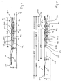
- FIG. 4 and Fig. 5 another example of a chassis is sketched, in which a loading upper frame LG front shows a gooseneck structure GS.
- longitudinally staggered transverse beams QT2, QT3 are longitudinally staggered relative to the rear cross member QT1 so as to be fully collapsed in the first operating position shown in Figure 1 in which the chassis is fully collapsed and the rear cross member QT1 is at the rear of the chassis Chassis is located between axle positions A2, A3 and spaced therefrom.
- This is also possible in the inserted first operating position as shown in Fig. 4, a lowering of the upper loading frame on ride height LL of the loading level possible.
- the loading frame on the pneumatic suspension on height LH lifted, with blocked wheels and dissolved longitudinal locking of the superstructure superstructure relative to the chassis frame pulled out to the front, again locked against unintentional displacement in the longitudinal direction and lowered back to driving height LL.
- the longitudinal transport positions are plotted as distance dimensions for various container types and with M20 for a single 20 'ISO container, M30 for a 30' ISO container, M20-1 and M20-2 for loading with two 20s 'ISO containers and M40 for a 40' ISO or HC container.
- a 40 'ISO container lies opposite the ride height LL of the loading level of the upper cargo frame increases at the height HG of the Gooseneck structure on the chassis, but remains with its upper edge still below the given height limit. This also applies when the chassis is loaded with two 20 'ISO containers for the forward M20-2 container in the direction of travel.
- a front-side extension FA additionally allows the extension of the chassis to the front to hold 45 'containers. HC containers are held at the front in the usual way by horizontally engaging in fittings of the container socket pin.
- Fig. 5 on the other hand, wherein in particular in the second operating position according to Fig. 3 and Fig. 5, the rear cross member QT1 longitudinally spaced between two wheel axles and the upper loading frame for driving is lowered.
- the control device may comprise components including sensors and actuators in electrical / electronic and / or mechanical and / or pneumatic design.
- the components as such are known and familiar to the expert.
- individual steps can be monitored by sensors for successful completion.
- message signals can be generated in each case.
Abstract
Description
Zum Transport von Containern sind Sattelcontainerfahrgestelle gebräuchlich, welche an Querträgern in unterschiedlichen Längspositionen Verriegelungen zum Eingriff in Container-Eckbeschläge aufweisen. Als Container sind insbesondere ISO-Container mit einer standardisierten Höhe von 2776 mm und HighCube (HC)-Container mit einer Höhe von 2896 mm gebräuchlich.For the transport of containers saddle container chassis are commonly used, which have on cross members in different longitudinal positions locks for engagement in container corner fittings. The containers used are in particular ISO containers with a standardized height of 2776 mm and HighCube (HC) containers with a height of 2896 mm.
Häufig werden die Container an Rampen entladen, wofür sie heckbündig auf dem Fahrgestell liegen müssen. Insbesondere bei Beladung eines Fahrgestells mit einem kurzen (20', in verringertem Maß auch 30') Container in heckbündiger Position ergibt sich eine ungünstige Lastverteilung mit zu geringer Lasteinwirkung auf die Sattelkupplung und die Antriebsräder des Zugfahrzeugs, was zu erheblichen Problemen im Fahrbetrieb führen kann.Often the containers are unloaded on ramps, for which they must lie flush-mounted on the chassis. In particular, when loading a chassis with a short (20 ', to a lesser extent 30') container in rear flush position results in an unfavorable load distribution with too little load on the fifth wheel and the drive wheels of the towing vehicle, which can lead to significant problems when driving.
Aus der
Es sind ferner längenverstellbare Containerchassis als Schlittenchassis teleskopierbare Chassis bekannt, welche in einen Fahrgestellrahmen (Bogie) und einen gegenüber diesem in Längsrichtung verschiebbaren und in verschiedenen Betriebspositionen in Längsrichtung arretierbaren Ladeoberrahmen unterteilt sind. Solche längenverstellbare Chassis ermöglichen in einer ganz eingeschobenen Position von Fahrgestellrahmen und Ladeoberrahmen die heckbündige Anordnung eines Containers zur Be- und Entladung auf dem Ladeoberrahmen und durch dessen Verschiebung in Fahrtrichtung die Positionierung des Containers mit ausreichender Belastung der Sattelkuppeln. Bei einem derartig ausziehbaren Chassis der Firma Renders sind die Kotflügel über den Rädern der hintersten Achse pneumatisch auf die Reifen absenkbar, um bei einer Längenänderung des Chassis den die Räder dabei überstreichenden hinteren Querträger nicht zu behindern. Ein vergleichbares längenveränderliches Chassis ist aus der
Bei einem aus der
Die
Der vorliegenden Erfindung liegt die Aufgabe zugrunde, ein längenverstellbares Containerchassis anzugeben, welches eine große Flexibilität hinsichtlich des sicheren Transports von Containern unter Einhaltung von Höhenbeschränkungen zeigt.The present invention has for its object to provide a length-adjustable container chassis, which shows a great deal of flexibility in terms of the safe transport of containers in compliance with height restrictions.
Die Erfindung ist im Patentanspruch 1 beschrieben. Die abhängigen Ansprüche enthalten vorteilhafte Ausgestaltungen und Weiterbildungen der Erfindung.The invention is described in claim 1. The dependent claims contain advantageous refinements and developments of the invention.
Die Erfindung ermöglicht durch die Höhenverstellbarkeit des Ladeoberrahmens in der zweiten Betriebsposition relativ zu dem auf einer Standfläche aufstehenden Rädersatz wenigstens einer Radachse zum einen eine Absenkung auf eine Fahrhöhe, bei welcher auch der Transport hoher HC-Container unter Einhaltung der Höhenbeschränkungen möglich ist, und zum anderen eine Anhebung des Laderahmens auf eine Verschiebehöhe, in welcher Teile von Ladeoberrahmen einerseits, insbesondere dessen hinterer Querträger, und Fahrgestell andererseits, insbesondere dessen hinterer Rädersatz mit Kotflügeln, bei der Längsverschiebung übereinander hinweg bewegt werden können. Als Fahrgestell sei hierbei die Baugruppe mit einem Fahrgestellrahmen und mit diesem verbundenen Rädern auf einer oder mehreren Radachsen verstanden. Als Bezugspunkt für Fahrhöhe und Verschiebehöhe sei die durch Querträger des Ladeoberrahmens bestimmte Ladeebene als Auflageebene für Container angenommen. Vorzugsweise stehen Ladeoberrahmen und Fahrgestellrahmen in gleichbleibender relativer Höhenlage und die Höhenverstellung des Ladeoberrahmens erfolgt gemeinsam mit dem Fahrgestellrahmen, wofür vorteilhafterweise eine typischerweise vorhandene pneumatische Federung des Fahrgestellrahmens eingesetzt werden kann. Ein Beispiel für eine Höhenverstellung eines Fahrgestells mittels der pneumatischen Federung ist beispielsweise der bereits genannten
Der auf Verschiebehöhe befindliche Ladeoberrahmen kann durch maximales Ineinanderschieben von Ladeoberrahmen und Fahrgestellrahmen in Längsrichtung zu einer minimalen Gesamtlänge des Chassis mit dem hinteren Querträger zum Heck des Fahrzeugs bzw. Fahrgestells verschoben werden, so dass ein auf dem hinteren Querträger und wenigstens einem weiteren Querträger des Ladeoberrahmens gehaltener Container eine heckbündige Position als erste Betriebsposition zum Be- und Entladen an einer Rampe einnimmt. Der hintere Querträger liegt in dieser ersten Betriebsposition in Längsrichtung hinter der hinteren Achsposition des Fahrgestells. Nach Abschluss des Be- oder Entladevorgangs wird der auf Verschiebehöhe befindliche Ladeoberrahmen mit dem darauf befindlichen Container relativ zum Fahrgestellrahmen nach vorne in die zweite Betriebsposition verschoben, typischerweise mittels des Zugfahrzeugs bei blockierten Rädern des Fahrgestells.The superelevated superstructure frame can be displaced longitudinally to a minimum overall length of the chassis with the rear cross member to the rear of the vehicle or chassis by telescoping the superstructure frame and chassis frame so that one held on the rear cross member and at least one further cross member of the upper deck frame Container occupies a rear-flush position as the first operating position for loading and unloading on a ramp. The rear cross member lies in this first operating position in the longitudinal direction behind the rear axle position of the chassis. After completion of the loading or unloading the superelevation loading upper frame is moved with the container thereon relative to the chassis frame forward to the second operating position, typically by means of the towing vehicle with locked wheels of the chassis.
In der zweiten Betriebsposition liegt der hintere Querträger des Ladeoberrahmens in Längsrichtung vor der hinteren Achsposition des Fahrgestells, bei einem bevorzugterweise mehrachsigen Fahrgestell vorteilhafterweise zwischen zwei Achspositionen, vorzugsweise von jeder Achsposition um wenigstens 50 %, insbesondere wenigstens 80 % eines Radhalbmessers des Rädersatzes in Längsrichtung beabstandet. Sofern weitere Betriebspositionen in Längsrichtungen als Fahrpositionen mit in Fahrhöhe befindlichem Ladeoberrahmen vorgesehen sind, gelten diese Merkmale analog. Bevorzugt sind genau zwei in Längsrichtung unterschiedliche Betriebspositionen vorgesehen.In the second operating position, the rear cross member of the loading upper frame is longitudinally in front of the rear axle position of the chassis, in a preferably multi-axle chassis advantageously between two axial positions, preferably spaced from each axle position by at least 50%, in particular at least 80% of a Radhalbmessers the wheelset in the longitudinal direction. If further operating positions in longitudinal directions are provided as driving positions with loading upper frame located at the ride height, these features apply analogously. Preferably, exactly two different longitudinal operating positions are provided.
In der zweiten Betriebsposition in Längsrichtung können Ladeoberrahmen und Fahrgestellrahmen in an sich bekannter Weise gegen Längsverschiebung lösbar arretiert werden. Nach Absenken des Ladeoberrahmens in der zweiten Betriebsposition auf die Fahrhöhe liegt die durch die Querträger bestimmte Ladeebene des Ladeoberrahmens so tief, insbesondere bei maximal 1150 mm, vorzugsweise maximal 1104 mm, dass auch HC-Container von dieser Höhe der Ladeebene aus die maximal zulässige Gesamthöhe, welche in den meisten europäischen Staaten auf 4000 mm (mit teilweiser Tolerierung bis 4060 mm) festgelegt ist, nicht überschreiten.In the second operating position in the longitudinal direction of loading upper frame and chassis frame in a conventional manner against longitudinal displacement solvable be arrested. After lowering the upper loading frame in the second operating position to the ride height determined by the crossbar loading level of the upper loading frame is so deep, especially at a maximum of 1150 mm, preferably at most 1104 mm, that HC container from this height of the loading level of the maximum total height, which in most European countries is set to 4000 mm (with partial tolerance up to 4060 mm).
In der Fahrhöhenposition des Oberrahmens können insbesondere die Unterkanten der Querträger des Ladeoberrahmens tiefer liegen als die Oberkanten (oder Scheitel) der Räder oder der diese überdeckenden Kotflügel. Pneumatische Fahrgestell-Federungen weisen typischerweise einen vertikalen Verstellbereich auf, innerhalb dessen ein Fahrbetrieb zulässig ist. Vorteilhafterweise liegt die Fahrhöhe im Sinne der vorliegenden Erfindung im unteren, die Verschiebehöhe im oberen Drittel eines solchen Verstellbereichs. Die Fahrhöhe kann vorteilhafterweise dadurch charakterisiert sein, dass bei auf Fahrhöhe befindlicher Ladeebene des Ladeoberrahmens die Ladeebene parallel zu einer ebenen Standfläche des mit einem Zugfahrzeug verbundenen Chassis verläuft. Bei auf Verschiebehöhe befindlicher Ladeebene ist diese dann durch die unveränderte Höhe der Sattelauflage leicht nach vorne fallend geneigt. Als Höhe der Ladeebene sei bei geneigter Ausrichtung jeweils deren höchster Punkt angesehen. Das Chassis kann bei Beladung mit einem ISO-Container u. U. auch bei auf Verschiebehöhe befindlicher Ladeebene eine zulässige Fahrposition einnehmen, welche aber nicht als Fahrhöhe im Sinne der vorliegenden Erfindung angesehen sei.In the ride height position of the upper frame, in particular, the lower edges of the cross member of the loading upper frame can be lower than the upper edges (or apex) of the wheels or the fenders covering them. Pneumatic chassis suspensions typically have a vertical range of adjustment within which driving is permitted. Advantageously, the ride height in the sense of the present invention is in the lower, the displacement height in the upper third of such an adjustment. The ride height can advantageously be characterized in that, when the loading level of the loading upper frame is at ride height, the loading level runs parallel to a flat footprint of the chassis connected to a towing vehicle. When located on the height of displacement loading level this is then inclined by the unchanged height of the saddle slightly sloping forward. The height of the loading level is considered to be the highest point when tilted. The chassis may load when loaded with an ISO container u. U. occupy a permissible driving position even at befindlichem on displacement height loading level, but which is not regarded as a ride height in the context of the present invention.
Die Bedingung, dass der hintere Querträger (und gegebenenfalls weitere Querträger des Ladeoberrahmens) in der zweiten Betriebsposition vor der hinteren Achsposition bzw. bei mehrachsigem Fahrgestellrahmen zwischen in Längsrichtung benachbarten Achspositionen liegt, beschränkt zwar die Wahl der Betriebspositionen für Fahrbetriebe in Längsrichtung, ermöglicht aber auf besonders vorteilhafte Weise den sicheren Fahrbetrieb unter Einhaltung von Höhenbegrenzungen für alle gebräuchlichen Containertypen und -größen. Vorteilhafterweise können insbesondere auch die im Markt bevorzugten großen Reifengrößen mit Durchmessern von 960-1060 mm eingesetzt und die Räder mit Kotflügelanordnungen überdeckt sein.The condition that the rear cross member (and optionally further cross member of the loading upper frame) in the second operating position in front of the rear axle position or in multiaxial chassis frame between in Longitudinal adjacent axle positions, although limited the choice of operating positions for driving companies in the longitudinal direction, but allows in a particularly advantageous manner safe driving while maintaining height limits for all common container types and sizes. Advantageously, in particular, the market in the preferred large tire sizes with diameters of 960-1060 mm used and the wheels are covered with fender arrangements.
Die Erfindung ist nachfolgend anhand bevorzugter Ausführungsbeispiele unter Bezugnahme auf die Abbildungen noch eingehend veranschaulicht. Dabei zeigt
- Fig. 1 ein eingefahrenes Chassis mit heckbündigem Container,
- Fig. 2 das Chassis in ausgezogener angehobener Position,
- Fig. 3 das Chassis in abgesenkter Position,
- Fig. 4 ein Gooseneck-Chassis in eingeschobener Position,
- Fig. 5 das Chassis nach Fig. 4 in ausgezogener Position.
- 1 is a retracted chassis with rear-flush container,
- 2 shows the chassis in the extended raised position,
- 3 shows the chassis in lowered position,
- 4 a gooseneck chassis in the inserted position,
- Fig. 5 shows the chassis of FIG. 4 in the extended position.
In Fig. 1 bis Fig. 3 ist schematisch ein Containerchassis in Form eines Sattelfahrgestells in Seitenansicht dargestellt. Das Chassis besteht im wesentlichen aus einem Fahrgestellrahmen FR mit drei Radachsen RA1, RA2, RA3 an drei in Längsrichtung LR beabstandeten Achspositionen A1, A2, A3 und einem Ladeoberrahmen LO, welcher in Längsrichtung relativ zu dem Fahrgestellrahmen verschiebbar an diesem geführt ist. In der Höhe sind Fahrgestellrahmen und Ladeoberrahmen fest gekoppelt.In Fig. 1 to Fig. 3, a container chassis in the form of a saddle chassis is shown schematically in side view. The chassis consists essentially of a chassis frame FR with three wheel axles RA1, RA2, RA3 at three longitudinally spaced LR axle positions A1, A2, A3 and a loading upper frame LO, which is slidably guided in the longitudinal direction relative to the chassis frame on this. The height of the chassis frame and the upper cargo frame are firmly coupled.
Auf dem Ladeoberrahmen LO sind an sich senkrecht zur Zeichenebene erstreckenden Querträgern QT1 bis QT5 Verriegelungen, z. B. Twist-Lock-Verriegelungen zum Eingriff in Eckbeschläge von Containern angeordnet. Die die Container abstützenden oberen Flächen der Querträger oder der Verriegelungen bestimmen eine Ladeebene, z. B. für einen 20'-ISO-Container 120. Die Rädersätze RS sind an dem Fahrgestellrahmen mit pneumatischer Federung aufgehängt. Die pneumatische Federung erlaubt in begrenztem Umfang eine Verstellung der Höhe des Fahrgestellrahmens und damit auch der Ladeebene über einer Fahrbahnfläche FB.On the upper loading frame LO are perpendicular to the plane extending cross members QT1 to QT5 latches, z. B. Twist-lock locks arranged for engagement in corner fittings of containers. The container supporting the upper surfaces of the cross member or the locks determine a loading level, z. B. for a 20 '
In den Abbildungen sind Situationen mit unterschiedlichen Betriebspositionen des Ladeoberrahmens in Längsrichtung relativ zum Fahrgestellrahmen und mit unterschiedlichen Höhen der Ladeebene dargestellt.In the figures, situations are shown with different operating positions of the loading upper frame in the longitudinal direction relative to the chassis frame and with different heights of the loading level.
In Fig. 1 sind Ladeoberrahmen LO und Fahrgestellrahmen FR in einer ersten Betriebsposition in Längsrichtung soweit ineinander geschoben, dass der hintere Querträger QT1 des Ladeoberrahmens, welcher typischerweise der hinterste Querträger des Chassis in Längsrichtung ist, im wesentlichen heckbündig am Chassis in einer Längsposition P11 angeordnet ist. Zusätzlich kann auch ein nach hinten teleskopisch ausfahrbarer Heckauszug mit weiteren Verriegelungen vorgesehen sein. Ein 20'-ISO-Container I20, welcher mit Eckbeschlägen an Verriegelungen der Querträger QT1, QT4 gehalten ist, befindet sich in heckbündiger Position und ist über eine Rampe, an welche das Chassis rückwärts gefahren wird, be- und entladbar. Das Chassis befindet sich in einem mittels der pneumatischen Federung angehobenen Zustand mit einer auf einer als Verschiebehöhe bezeichneten oberen Ladehöhe LH befindlichen Ladeebene LE. Ladeoberrahmen und Fahrgestellrahmen sind vorzugsweise in der ersten Betriebsposition gegen unbeabsichtigte Längsverschiebung relativ zueinander lösbar arretiert, z. B. über eine Bolzenverriegelung.In Fig. 1, loading upper frame LO and chassis frame FR are pushed into each other in a first operating position in the longitudinal direction so far that the rear cross member QT1 of the loading upper frame, which is typically the rearmost cross member of the chassis in the longitudinal direction, is arranged substantially rear-flush on the chassis in a longitudinal position P11 , In addition, a rear telescopic extendable rear extension can be provided with other locks. A 20 'ISO container I20, which is held with corner fittings on locks of the cross member QT1, QT4, is in a rear-flush position and is on a ramp to which the chassis is driven backwards, loading and unloading. The chassis is in a raised state by means of the pneumatic suspension with a loading level LE located on an upper loading height LH designated as a displacement height. Loading upper frame and chassis frame are preferably releasably locked in the first operating position against unintentional longitudinal displacement relative to each other, for. B. via a bolt lock.
In der in Fig. 1 skizzierten Situation befinden sich die Unterkanten der Querträger, insbesondere des hinteren Querträgers QT1 in einer Höhe HQ, welche größer ist als die Höhe HR der Scheitelpunkte/Oberkanten der Rädersätze RS und wie im Beispielsfall der die Rädersätze überdeckenden Kotflügelanordnungen KA1, KA2, KA3, insbesondere der Kotflügelanordnung KA1 über dem Rädersatz der hinteren Radachse RA1.In the situation outlined in FIG. 1, the lower edges of the cross members, in particular of the rear cross member QT1, are at a height HQ which is greater than the height HR of the vertices / upper edges of the wheel sets RS and, as in the example of the fender sets KA1 covering the wheel sets, KA2, KA3, in particular the fender arrangement KA1 above the wheelset of the rear wheel axle RA1.
Das Gewicht des auf dem Ladeoberrahmen LO gehaltenen kurzen 20'-Containers I20 ist im wesentlichen durch die Räder des Fahrgestellrahmens getragen und belastet unzureichend ein Zugfahrzeug, welches über eine am frontseitigen Ende des Ladeoberrahmens befindliche Sattelkupplung verbunden ist. Die in Fig. 1 skizzierte erste Betriebsposition des Ladeoberrahmens in Längsrichtung relativ zum Fahrgestellrahmen ist deshalb für den Fahrbetrieb bei der gegebenen Beladung ungünstig.The weight of the short 20 'container I 20 held on the upper cargo frame LO is substantially supported by the wheels of the chassis frame and insufficiently loads a towing vehicle connected by a fifth wheel at the front end of the upper cargo frame. The sketched in Fig. 1 first operating position of the upper loading frame in the longitudinal direction relative to the chassis frame is therefore unfavorable for driving at the given load.
In an sich bekannter Weise kann der Ladeoberrahmen relativ zum Fahrgestellrahmen ausgezogen werden, indem die Räder des Fahrgestellrahmens über dessen Bremsanlage blockiert werden und mittels des Zugfahrzeugs der Ladeoberrahmen in Längsrichtung verschoben wird in eine in Fig. 2 skizzierte zweite Betriebsposition des Ladeoberrahmens in Längsrichtung relativ zum Fahrgestellrahmen. Erforderlichenfalls ist eine in der ersten Betriebsposition nach Fig. 1 gegebene Arretierung zwischen Ladeoberrahmen und Fahrgestellrahmen zuvor zu lösen. Eine solche Arretierung, z. B. über einen federbelasteten Bolzen oder Haken, rückt vorteilhafterweise bei der Längsverschiebung des Ladeoberrahmens relativ zum Fahrgestellrahmen bei Erreichen der in Fig. 2 skizzierten zweiten Betriebsposition selbsttätig ein und verhindert eine weitere Verschiebung in Längsrichtung. Bei nur zwei Betriebspositionen kann die Längsverschiebung auch durch einen Endanschlag begrenzt sein.In a manner known per se, the upper loading frame can be pulled out relative to the chassis frame by the wheels of the chassis frame are blocked by the brake system and by means of the towing vehicle of the loading upper frame is displaced in the longitudinal direction in a sketched in Fig. 2 second operating position of the loading upper frame in the longitudinal direction relative to the chassis frame , If necessary, a given in the first operating position shown in FIG. 1 locking between superstructure frame and chassis frame to solve previously. Such a lock, z. B. via a spring-loaded bolt or hook, advantageously moves automatically in the longitudinal displacement of the upper loading frame relative to the chassis frame upon reaching the sketched in Fig. 2 second operating position and prevents further displacement in the longitudinal direction. With only two operating positions, the longitudinal displacement can also be limited by an end stop.
Während der Verschiebung bleibt die Verschiebehöhe LH der Ladeebene so weit erhalten, dass die Unterkante des ersten Querträgers QT1 zuverlässig oberhalb der Kotflügelanordnung KA1 bleibt. Insbesondere kann während der Verschiebung von der ersten Betriebsposition in die zweite Betriebsposition die Höhe der Ladeebene im wesentlichen konstant auf der Verschiebehöhe LH bleiben.During the displacement, the shift height LH of the loading plane is maintained so far that the lower edge of the first cross member QT1 reliably remains above the fender arrangement KA1. In particular, during the shift from the first operating position to the second operating position, the height of the loading plane may remain substantially constant at the displacement height LH.
In der in Fig. 2 dargestellten zweiten Betriebsposition belastet das Gewicht des Containers 120 günstigerweise auch in nennenswertem Ausmaß über die Sattelkupplung das Zugfahrzeug und verbessert damit die Fahreigenschaften gegenüber der in Fig. 1 skizzierten ersten Betriebsposition. Die Länge des Chassis ist in der zweiten Betriebsposition größer als in der ersten Betriebsposition. In der in Fig. 2 skizzierten zweiten Betriebsposition des Ladeoberrahmens in Längsrichtung relativ zum Fahrgestellrahmen befindet sich der hintere (erste) Querträger QT1 in Längsrichtung vor der Achsposition A1 der hinteren Radachse RA1, bei dem gegebenen Beispiel mit dem mehrachsigen Fahrgestellrahmen zwischen der ersten Achsposition A1 und der dieser in Längsrichtung benachbarten Achsposition A2. Vorteilhafterweise liegt die Längsposition P21 in der in Fig. 2 skizzierten zweiten Betriebsposition in einem Zwischenbereich ZB sowohl von der hinteren (ersten) als auch von der zweiten Achsposition um ein Maß DA beabstandet, welches vorzugsweise wenigstens 50 %, insbesondere wenigstens 80 % des Radhalbmessers RR der Räder beträgt. Die Längsposition P22 des zweiten Querträgers QT2 liegt in der zweiten Betriebsposition vor der Achsposition A3 der dritten, vordersten Radachse RA3.In the second operating position shown in FIG. 2, the weight of the
In der zweiten Betriebsposition des Ladeoberrahmens relativ zum Fahrgestellrahmen kann der Fahrgestellrahmen mit dem Ladeoberrahmen in gegenseitig arretierter Position mittels der pneumatischen Federung des Fahrgestells abgesenkt werden auf eine in Fig. 3 skizzierte tiefere Position mit einer gegenüber LH reduzierten unteren Höhe LL der Ladeebene des Ladeoberrahmens LO. In dieser abgesenkten Position kann insbesondere die Unterkante UK1 des hinteren Querträgers QT1 auf einer Höhe LQ liegen, welche niedriger ist als die bei der Absenkung im wesentlichen unveränderte Höhe HR der Oberkante der Räder oder gegebenenfalls der Kotflügelanordnung KA1. Wesentlich an der abgesenkten Position nach Fig. 3 ist, dass ein auf die Ladeebene in der unteren Ladehöhe LL aufgesetzter Container H40 mit einer standardisierten Containerhöhe, insbesondere ein Highcube-Container, eine Gesamthöhe HH des beladenen Chassis zeigt, welche eine gesetzlich vorgegebene Höhenbegrenzung HB für den Containertransport nicht überschreitet. Die für den Fahrbetrieb abgesenkte Position nach Fig. 3 sei daher als Fahrposition und die dabei von der Ladeebene eingenommene untere Ladehöhe als Fahrhöhe angenommen. Im Gegensatz dazu sei die angehobene Position nach Fig. 1 und Fig. 2 als Verschiebeposition mit auf Verschiebehöhe liegender Ladeebene bezeichnet. Eine Verschiebung des Ladeoberrahmens zwischen der ersten und der zweiten Betriebsposition ist nur in der auf Verschiebehöhe angehobenen Position möglich.In the second operating position of the loading upper frame relative to the chassis frame, the chassis frame with the loading upper frame in each other Locked position can be lowered by means of the pneumatic suspension of the chassis to a sketched in Fig. 3 lower position with a reduced compared to LH lower level LL of the loading level of the loading upper frame LO. In this lowered position, in particular the lower edge UK1 of the rear cross member QT1 can be at a height LQ which is lower than the height HR of the upper edge of the wheels or possibly the fender arrangement KA1 which is substantially unchanged during the lowering. Essential to the lowered position of FIG. 3 is that a placed on the loading level in the lower loading height LL container H40 with a standardized container height, in particular a high-cube container, a total height HH of the loaded chassis shows a legally prescribed height limit HB for does not exceed the container transport. The lowered position for the driving operation according to FIG. 3 is therefore assumed to be the driving position and the bottom loading height assumed by the loading plane as the driving height. In contrast, the raised position according to FIG. 1 and FIG. 2 is referred to as a displacement position with a loading plane lying at a displacement height. A displacement of the loading upper frame between the first and the second operating position is possible only in the raised position to the displacement.
Insbesondere kann der Container H40, welcher in Fig. 3 zusätzlich zu dem in Fig. 1 und Fig. 2 angenommenen kurzen Container I20 eingezeichnet ist, ein HC-Container mit z. B. 40' Containerlänge und mit einer Containerhöhe ZH=2896 mm sein, für dessen Transport bei einer gegebenen Höhenbegrenzung von 4000 mm die Fahrhöhe LL maximal 1104 mm beträgt. Durch gezeichnete Unterbrechung des Chassis und des Containers H40 in Fig. 3 sei angedeutet, dass die absolute Länge des Chassis für die vorliegende Erfindung nachrangig ist. Das Chassis kann frontseitig bei der Sattelkupplung einen zusätzlichen Auszug zur Längenveränderung besitzen und/oder eine Gooseneck-Struktur, welche in mittige Tunnel an der Unterseite von HC-Containern eintaucht, aufweisen. Zur Halterung längerer Container ist in an sich bekannter Art am Heck des Fahrgestellrahmens eine weitere Verriegelung HV vorgesehen, welche in Fig. 1 nach unten weggeklappt gezeichnet ist. Außerdem kann ein nach hinten verschiebbarer Heckauszug vorgesehen sein.In particular, the container H40, which is shown in Fig. 3 in addition to the assumed in Fig. 1 and Fig. 2 short container I20, an HC container with z. B. 40 'container length and with a container height ZH = 2896 mm, for the transport at a given height limit of 4000 mm, the ride height LL is a maximum of 1104 mm. By drawn interruption of the chassis and the container H40 in Fig. 3 is indicated that the absolute length of the chassis for the present invention is subordinate. The chassis may have an additional extension to the length change at the front of the fifth wheel and / or a gooseneck structure, which dips into central tunnels at the bottom of HC containers, exhibit. For holding longer container a further locking HV is provided in a conventional manner at the rear of the chassis frame, which is drawn folded down in Fig. 1. In addition, a rearward sliding rear extension can be provided.
Das Prinzip der abgesenkten Fahrposition nach Fig. 3 ermöglicht die Einhaltung der Höhenbegrenzung beim Transport unter Beibehaltung bewährter und gebräuchlicher, die minimale Ladehöhe beim Verschiebevorgang beeinflussender Komponenten. Insbesondere kann eine vorteilhafte Höhe der Querträger und Verriegelungen von typischerweise 80-140 mm beibehalten werden. Auch hinsichtlich des Räderdurchmessers, bei welchem für die Höhe HR gegebenenfalls noch Federweg sowie Abstand und Eigenhöhe von die Räder abdekkenden Kotflügelanordnungen zu berücksichtigen sind, ermöglicht die Erfindung die Beibehaltung gebräuchlicher Reifengrößen. Kotflügelanordnungen sind gegebenenfalls nicht wie herkömmlich starr mit dem Fahrgestellrahmen verbunden sondern vertikal mit den federnd aufgehängten Rädern verbunden, insbesondere an den Radachsen befestigt. Die Fahrhöhe der Luftfederung ist vorteilhafterweise an die gegenüber herkömmlichen längenveränderbaren Chassis tiefere Lage des Fahrgestellrahmens in der Fahrposition nach Fig. 3, insbesondere hinsichtlich der Sicherstellung eines ausreichenden Federwegs im Fahrbetrieb, angepasst. Innerhalb eines vertikalen Verstellbereichs der Höhe der Ladeebene mittels der pneumatischen Federung liegt vorteilhafterweise die Verschiebehöhe im oberen Drittel und die Fahrhöhe im unteren Drittel eines solchen Verstellbereichs.The principle of the lowered driving position of FIG. 3 allows compliance with the height limit during transport while maintaining proven and common, the minimum loading height during the displacement process influencing components. In particular, an advantageous height of the cross members and latches of typically 80-140 mm can be maintained. Also with regard to the wheel diameter, in which for the height HR optionally still spring travel and distance and altitude of the wheels cover off the fender arrangements are to be considered, the invention allows the maintenance of common tire sizes. Fender assemblies may not be as conventional rigidly connected to the chassis frame but vertically connected to the spring-mounted wheels, in particular attached to the wheel axles. The ride height of the air suspension is advantageously adapted to the compared to conventional variable-length chassis deeper position of the chassis frame in the driving position of FIG. 3, in particular with regard to ensuring a sufficient travel when driving. Within a vertical adjustment range of the height of the loading plane by means of the pneumatic suspension is advantageously the displacement height in the upper third and the ride height in the lower third of such an adjustment.
Die Ladeebene verläuft bei bei Anheben oder Absenken des Ladeoberrahmens unveränderter Höhe des Auflagers eines Zugfahrzeugs im Frontbereich des Chassis nur in einer Höhenposition, vorzugsweise der Fahrhöhe, parallel zu einer ebenen Standfläche FB und in anderer Höhenposition leicht gegen eine solche ebene Standfläche gezeigt. Die Höhenvariation tritt dann im wesentlichen im Heckbereich des Chassis in Erscheinung. Die Höhe der Ladeebene im Frontbereich des Chassis ist dann für alle Höhenpositionen des Ladeoberrahmens relativ zu den Radachsen gleich der Fahrhöhe und während des Verschiebevorgangs niedriger als die Verschiebehöhe der Ladeebene, welche im Heckbereich vorliegt.The loading level runs when lifting or lowering the upper cargo frame unchanged height of the support of a towing vehicle in the front of the chassis only in a vertical position, preferably the ride height, parallel to a flat footing FB and in another height position slightly against a such flat floor space shown. The height variation then occurs essentially in the rear of the chassis in appearance. The height of the loading level in the front region of the chassis is then equal to the ride height for all height positions of the loading upper frame relative to the wheel axles and lower than the displacement height of the loading plane which is present in the rear area during the shifting process.
Auch für einen Container geringerer Containerhöhe wie z. B. in Fig. 3 den Container I20 mit ISO-Standardmaß ZI=2776 mm, welcher eventuell in der angehobenen Position nach Fig. 2 noch innerhalb der Höhenbegrenzung HB liegen kann, erfolgt zum Transport vorteilhafterweise eine Absenkung der Ladeebene von der Verschiebehöhe LH auf die niedrigere Position der Fahrhöhe LL nach Fig. 3 oder eine Zwischenposition.Also for a container lower container height such. B. in Fig. 3, the container I20 with ISO standard size ZI = 2776 mm, which may be located in the raised position of Fig. 2 still within the height limit HB, advantageously carried to transport a lowering of the loading level of the displacement height LH on the lower position of the ride height LL of FIG. 3 or an intermediate position.
In Fig. 4 und Fig. 5 ist ein weiteres Beispiel eines Chassis skizziert, bei welchem ein Ladeoberrahmen LG frontseitig eine Gooseneck-Struktur GS zeigt. Bei diesem Beispiel sind gegen den hinteren Querträger QT1 in Längsrichtung versetzt angeordnete Querträger QT2, QT3 so in Längsrichtung positioniert, dass sie in der in Fig. 1 skizzierten ersten Betriebsposition, in welcher das Chassis ganz zusammengeschoben ist und der hintere Querträger QT1 sich am Heck des Chassis befindet, zwischen Achspositionen A2, A3 und von diesen beabstandet liegen. Damit ist auch in der eingeschobenen ersten Betriebsposition wie in Fig. 4 skizziert eine Absenkung des Ladeoberrahmens auf Fahrhöhe LL der Ladeebene möglich.In Fig. 4 and Fig. 5, another example of a chassis is sketched, in which a loading upper frame LG front shows a gooseneck structure GS. In this example, longitudinally staggered transverse beams QT2, QT3 are longitudinally staggered relative to the rear cross member QT1 so as to be fully collapsed in the first operating position shown in Figure 1 in which the chassis is fully collapsed and the rear cross member QT1 is at the rear of the chassis Chassis is located between axle positions A2, A3 and spaced therefrom. This is also possible in the inserted first operating position as shown in Fig. 4, a lowering of the upper loading frame on ride height LL of the loading level possible.
Zum Ausziehen des Chassis in die in Fig. 5 skizzierte zweite Betriebsposition wird, wie durch Pfeile B1, B2 angedeutet, der Laderahmen über die pneumatische Federung auf Verschiebehöhe LH angehoben, bei blockierten Rädern und gelöster Längsarretierung der Ladeoberrahmen gegenüber dem Fahrgestellrahmen nach vorne ausgezogen, erneut gegen unbeabsichtigtes Verschieben in Längsrichtung arretiert und wieder auf Fahrhöhe LL abgesenkt. In Fig. 5 sind die Transportpositionen in Längsrichtung für verschiedene Containertypen als Abstandsmaße eingetragen und mit M20 für einen einzelnen 20'-ISO-Container, M30 für einen 30'-ISO-Container, M20-1 und M20-2 für Beladung mit zwei 20'-ISO-Containern sowie M40 für einen 40'ISO- oder HC-Container bezeichnet. Ein 40'-ISO-Container liegt dabei gegenüber der Fahrhöhe LL der Ladeebene des Ladeoberrahmens erhöht auf der Höhe HG der Gooseneck-Struktur auf dem Chassis auf, bleibt aber mit seiner Oberkante noch unter der vorgegebenen Höhenbeschränkung. Dies gilt entsprechend auch bei Beladung des Chassis mit zwei 20'-ISO-Containern für den in Fahrtrichtung vorne liegenden Container M20-2. Ein frontseitiger Auszug FA erlaubt zusätzlich die Verlängerung des Chassis nach vorne zur Halterung von 45'-Containern. HC-Container werden frontseitig in üblicher Weise durch horizontal in Beschläge des Containers eingreifende Steckbolzen gehalten.To pull out the chassis in the sketched in Fig. 5 second operating position, as indicated by arrows B1, B2, the loading frame on the pneumatic suspension on height LH lifted, with blocked wheels and dissolved longitudinal locking of the superstructure superstructure relative to the chassis frame pulled out to the front, again locked against unintentional displacement in the longitudinal direction and lowered back to driving height LL. In Fig. 5, the longitudinal transport positions are plotted as distance dimensions for various container types and with M20 for a single 20 'ISO container, M30 for a 30' ISO container, M20-1 and M20-2 for loading with two 20s 'ISO containers and M40 for a 40' ISO or HC container. A 40 'ISO container lies opposite the ride height LL of the loading level of the upper cargo frame increases at the height HG of the Gooseneck structure on the chassis, but remains with its upper edge still below the given height limit. This also applies when the chassis is loaded with two 20 'ISO containers for the forward M20-2 container in the direction of travel. A front-side extension FA additionally allows the extension of the chassis to the front to hold 45 'containers. HC containers are held at the front in the usual way by horizontally engaging in fittings of the container socket pin.
Wenn der einzelne 20'-Container an M20 oder der 30'-Container an M30 auch bei auf Verschiebehöhe liegender Ladeebene noch innerhalb der Höhenbeschränkung HG liegt, kann bei solcher Beladung auch mit auf Verschiebehöhe befindlicher Ladeebene gefahren werden, so dass die Längsposition des ersten Querträgers QT1 für solche Beladungssituationen unkritisch ist und von der zweiten Betriebsposition verschieden sein kann und nur bei HC-Containern und bei auf der Gooseneck-Struktur aufliegenden ISO-Containern für Fahrbetrieb eine Absenkung der Ladeebene erforderlich ist und der erste Querträger bei auf Fahrhöhe LL abgesenkter Ladeebene in Längsrichtung zwischen zwei Achspositionen liegt und zwischen benachbarte Räder R1, R2 bzw. Kotflügelanordnungen KA1, KA2 eintaucht. Entsprechendes gilt auch für das in Fig. 1 bis Fig. 3 skizzierte Chassis. Bevorzugt sind aber Ausführungsformen mit genau zwei Betriebspositionen nach Fig. 1 bzw. Fig. 4 einerseits und Fig. 3 bzw.If the individual 20 'container on M20 or the 30' container on M30 is still within the height limit HG even with the loading level lying at a height of displacement, it is also possible to travel with the loading level at a displacement height such that the longitudinal position of the first cross member QT1 is not critical for such loading situations and may be different from the second operating position and only for HC containers and resting on the gooseneck structure ISO containers for driving a lowering of the loading level is required and the first cross member with lowered to driving height LL loading level in Lying longitudinally between two axle positions and between adjacent wheels R1, R2 or fender arrangements KA1, KA2 dips. The same applies to the chassis sketched in FIGS. 1 to 3. However, embodiments with exactly two operating positions according to FIG. 1 or FIG. 4 on the one hand and FIG. 3 or
Fig. 5 andererseits, wobei insbesondere in der zweiten Betriebsposition nach Fig. 3 bzw. Fig. 5 der hintere Querträger QT1 in Längsrichtung beabstandet zwischen zwei Radachsen liegt und der Ladeoberrahmen für Fahrbetrieb absenkbar ist.Fig. 5 on the other hand, wherein in particular in the second operating position according to Fig. 3 and Fig. 5, the rear cross member QT1 longitudinally spaced between two wheel axles and the upper loading frame for driving is lowered.
Für die Verschiebung des Ladeoberrahmens mit dem Container aus der ersten Betriebsposition nach Fig. 1 in die Fahrposition nach Fig. 3 können die einzelnen Vorgänge nacheinander manuell oder teilautomatisiert abgewickelt werden. Bei rein manueller Abwicklung wird beispielsweise
- a) soweit nicht bereits gegeben, über eine Ventilanordnung der pneumatischen Federung des Fahrgestells der Fahrgestellrahmen und der Ladeoberrahmen mit Container auf die Verschiebehöhe LH angehoben,
- b) die Bremsanlage des Fahrgestells, soweit nicht bereits gegeben, auf Rangierbetrieb mit Blockade der Räder gestellt,
- c) die Arretierung, z. B. Verriegelungsbolzen zwischen Ladeoberrahmen und Fahrgestellrahmen gelöst,
- d) durch kurzes Vorfahren des Zugfahrzeugs der Ladeoberrahmen so weit ausgezogen, dass der Verriegelungsbolzen von seiner Arretierungsposition der ersten Betriebsposition beabstandet ist,
- e) der Verriegelungsbolzen unter Vorspannung an eine Gleitfläche des Fahrgestellrahmens oder des Ladeoberrahmens angelegt,
- f) durch erneutes Vorfahren des Zugfahrzeugs der Ladeoberrahmen gegen den Fahrgestellrahmen weiter ausgezogen, bis der Verriegelungsbolzen unter der Vorspannung in die nächste Arretierungsposition entsprechend der zweiten Betriebsposition nach Fig. 2 einrastet,
- g) über die Ventilanordnung der Fahrgestellrahmen mit Ladeoberrahmen und Container in die tiefere Fahrposition mit der Ladeebene auf Fahrhöhe nach Fig. 3 abgesenkt,
- h) die Bremsanlage auf Fahrbetrieb umgestellt,
- i) der Transport gestartet.
- a) if not already given, raised via a valve arrangement of the pneumatic suspension of the chassis of the chassis frame and the upper cargo frame with container on the displacement height LH,
- b) the brake system of the chassis, if not already given, put on shunting with blockage of the wheels,
- c) the lock, z. B. locking bolt between superstructure upper frame and chassis frame,
- d) extended by briefly ancestor of the towing vehicle of the loading upper frame so far that the locking bolt is spaced from its locking position of the first operating position,
- e) the locking bolt is biased against a sliding surface of the chassis frame or the upper loading frame,
- f) by further ancestors of the towing vehicle of the superstructure upper frame against the chassis frame further pulled out until the locking pin engages under the bias in the next locking position corresponding to the second operating position of FIG. 2,
- g) lowered over the valve assembly of the chassis frame with superstructure upper frame and container in the lower driving position with the loading level at ride height of Fig. 3,
- h) the brake system switched to driving,
- i) the transport started.
Die manuelle Vorgehensweise kann insbesondere durch den mehrfachen Wechsel zwischen Anhänger und Zugfahrzeug als umständlich und zeitraubend empfunden werden, so dass gemäß einer vorteilhaften Weiterentwicklung mehrere oder vorzugsweise alle der herkömmlicherweise durch handbetätigte Bedienelemente am Chassis ausgelösten vorgenannten Vorgänge leitungsgebunden oder drahtlos ferngesteuert vom Zugfahrzeug aus veranlasst werden können, wofür dann vorteilhafterweise am Chassis entsprechende Sensoren z. B. für die Längsverschiebung und/oder die Höhenverstellung und/oder die Arretierung und/oder die Bremsanlage und im Zugfahrzeug entsprechende Anzeige- oder Meldeeinrichtungen vorgesehen sind. Gemäß einer bevorzugten Ausführungsform kann eine Steuereinrichtung eine Folge von ansonsten manuell ausgelösten Vorgängen automatisch abwickeln und dabei jeweils den Vollzug vorangegangener Schritte überwachen. Insbesondere kann vorteilhafterweise vorgesehen sein, dass der Fahrer ausgehend von der ersten Betriebsposition über entsprechende Bedieneinrichtungen pauschal einen Verschiebevorgang von der ersten Betriebsposition nach Fig. 1 in die abgesenkte Fahrposition nach Fig. 3 startet und daraufhin die Steuereinrichtung nacheinander die Schritte
- A1) soweit sich die Ladeebene nicht bereits auf Verschiebehöhe befindet, Anhebung von Fahrgestellrahmen und Laderahmen mittels der pneumatischen Federung,
- A2) überwachen der Höhe des Fahrgestellrahmens oder Ladeoberrahmens, bzw. der Ladeebene,
- A3) bei auf Verschiebehöhe befindlicher Ladeebene Beenden des Anhebens,
- A4) überprüfen der Blockierung der Räder und erforderlichenfalls Betätigen der Bremsanlage,
- A5) Lösen der Verriegelung zwischen Ladeoberrahmen und Fahrgestellrahmen,
- A6) Ausziehsignal an den Fahrer
- A1) as far as the loading level is not already at a height of displacement, raising of the chassis frame and loading frame by means of the pneumatic suspension,
- A2) monitor the height of the chassis frame or upper loading frame, or the loading level,
- A3) when the loading level is at the height of displacement, stop the lifting,
- A4) check the locking of the wheels and, if necessary, actuate the brake system,
- A5) release the interlock between the upper frame and the chassis frame,
- A6) Pull-out signal to the driver
Der Fahrer zieht durch Vorfahren des Zugfahrzeugs den Ladeoberrahmen gegenüber dem Fahrgestellrahmen aus bis in die zweite Betriebsposition. Vorteilhafterweise nimmt die Verriegelungseinrichtung nach Beginn des Ausziehvorgangs eine in dem Sinne vorgespannte Stellung ein, dass sie bei Erreichen der zweiten Betriebsposition automatisch Ladeoberrahmen und Fahrgestellrahmen wieder gegen Längsverschiebung verriegelt. Bei vorzugsweise genau zwei unterschiedlichen Betriebspositionen kann der Ausziehvorgang durch einen Anschlag begrenzt sein. Das Erreichen der zweiten Betriebsposition mit Sperren eines weiteren Ausziehens erkennt der Fahrer im Prinzip am Verhalten des Zugfahrzeugs, die Steuereinrichtung kann aber auch en Signal hierzu erzeugen, insbesondere optisch oder akustisch. Alternativ oder zusätzlich kann die Steuereinrichtung in der zweiten Betriebsposition eine Schriftfolge mit
- B1) Überprüfen der Verriegelung und eventuell zusätzliches Sichern gegen Entriegeln,
- B2) Absenken von Fahrgestellrahmen und Ladeoberrahmen mittels der pneumatischen Federung,
- B3) Überwachen der Höhe des Fahrgestellrahmens oder Laderahmens,
- B4) bei auf Fahrhöhe befindlicher Ladeebene Beenden des Absenkens,
- B5) Aufheben der Blockierung der Räder,
- B6) Fahrfreigabesignal an den Fahrer
- B1) Check the locking and possibly additional securing against unlocking,
- B2) Lowering of chassis frame and loading upper frame by means of the pneumatic suspension,
- B3) monitoring the height of the chassis frame or loading frame,
- B4) when the loading level is at ride height, ending the lowering,
- B5) Unblocking the wheels,
- B6) Drive release signal to the driver
Die Steuereinrichtung kann Bauelemente einschließlich Sensoren und Aktuatoren in elektrischer/elektronischer und/oder mechanischer und/oder pneumatischer Bauform umfassen. Die Bauelemente als solche sind bekannt und dem Fachmann geläufig. Vorteilhafterweise können einzelne Schritte durch Sensoren auf erfolgreichen Abschluss überwacht werden. Für einzelne abgeschlossene Schritte können jeweils Meldesignale erzeugt werden.The control device may comprise components including sensors and actuators in electrical / electronic and / or mechanical and / or pneumatic design. The components as such are known and familiar to the expert. Advantageously, individual steps can be monitored by sensors for successful completion. For individual completed steps, message signals can be generated in each case.
Die vorstehend und die in den Ansprüchen angegebenen sowie die den Abbildungen entnehmbaren Merkmale sind sowohl einzeln als auch in verschiedener Kombination vorteilhaft realisierbar. Die Erfindung ist nicht auf die beschriebenen Ausführungsbeispiele beschränkt, sondern im Rahmen fachmännischen Könnens in mancherlei Weise abwandelbar.The features indicated above and in the claims, as well as the features which can be seen in the figures, can be implemented advantageously both individually and in various combinations. The invention is not limited to the exemplary embodiments described, but can be modified in many ways within the scope of expert knowledge.
Claims (12)
- Length-adjustable container chassis having a chassis frame and an upper loading frame which can be displaced longitudinally relative to this chassis frame between at least two operating positions, it being the case that- the chassis frame (FR) has at least one rear set of wheels on a rear wheel axle (RA1) at a rear axial position (A1),- the upper loading frame (LO) has, in a rear region, a rear crossmember (QT1),- in a first operating position of the upper loading frame, with a short chassis length, the rear crossmember (QT1) is located behind the rear axial position (A1), as seen in the longitudinal direction (P11),- in a second operating position of the upper loading frame, with a longer chassis length, the rear crossmember (QT1) is located in front of the rear axial position (A1), as seen in the longitudinal direction (P21),characterized in that- the upper loading frame, in the second operating position, can be vertically adjusted between a travelling height (LL) and a displacement height (LH) of a loading plane,- displacement of the upper loading frame between the first and the second operating positions is possible only at the displacement height (LH).
- Container chassis according to Claim 1, characterized in that the chassis frame has a plurality of longitudinally offset wheel axles, and in that the rear crossmember (QT1), in the second operating position, is located between two axial positions (A1, A2), as seen in the longitudinal direction (P21).
- Container chassis according to Claim 1 or 2, characterized in that the rear crossmember (QT1), in the second operating position, is spaced apart (DA) from axial positions (A1, A2) of the chassis frame by at least 50%, in particular at least 80%, of a wheel radius (RR), as seen in the longitudinal direction.
- Container chassis according to one of Claims 1 to 3, characterized in that the difference between the travelling height (LL) and displacement height (LH) is at least 80 mm, in particular at least 120 mm.
- Container chassis according to one of Claims 1 to 4, characterized in that the travelling height (LL) of the loading plane of the upper loading frame is not more than 1150 mm, in particular not more than 1104 mm.
- Container chassis according to one of Claims 1 to 5, characterized in that the wheels on the rear wheel axle (RA1) are covered over by mudguard arrangements (KA1) and, with the chassis frame at the travelling height, the bottom edge of the rear crossmember is located at a lower level (HQ) than the top edge (HR) of the mudguard arrangements (KA1).
- Container chassis according to one of Claims 1 to 6, characterized in that the vertical adjustment of the upper loading frame takes place via pneumatic elements of the pneumatic chassis suspension.
- Container chassis according to one of Claims 1 to 7, characterized in that it is not possible to alter the relative vertical position of the upper loading frame (LO) and chassis frame (FR), and the vertical adjustment of the upper loading frame takes place by virtue of the chassis frame being vertically adjusted relative to the rear set of wheels.
- Container chassis according to one of Claims 1 to 8, characterized in that the upper loading frame (LO) has a gooseneck structure (GS) at its front end.
- Container chassis according to one of Claims 1 to 9, characterized in that a control arrangement coordinates the displacement of the upper loading frame and the vertical adjustment of the chassis frame.
- Container chassis according to Claim 10, characterized in that the control arrangement contains an input means for a start signal for displacement of the upper loading frame and, if a start signal is given,a) checks and, if necessary, provides for a blocking action of the brakes of the chassis,b) checks and, if necessary, provides for raising of the chassis frame from the travelling height to the displacement height,c) once the displacement height has been reached, with the brakes blocked, releases an arresting action between the chassis frame and upper loading frame,d) emits a release signal to the driver of a towing vehicle.
- Container chassis according to Claim 10 or 11, characterized in that the control arrangement monitors an arresting action between the chassis frame and upper loading frame when the next operating position is reached and, when the second operating position is reached, causes the chassis frame to be lowered to the travelling height and emits a termination signal to the driver of a towing vehicle.
Priority Applications (2)
| Application Number | Priority Date | Filing Date | Title |
|---|---|---|---|
| SI200430553T SI1486375T1 (en) | 2003-06-13 | 2004-05-06 | Length-adjustable container-chassis |
| PL04010747T PL1486375T3 (en) | 2003-06-13 | 2004-05-06 | Length-adjustable container-chassis |
Applications Claiming Priority (2)
| Application Number | Priority Date | Filing Date | Title |
|---|---|---|---|
| DE10327075 | 2003-06-13 | ||
| DE10327075A DE10327075A1 (en) | 2003-06-13 | 2003-06-13 | Length adjustable container chassis |
Publications (3)
| Publication Number | Publication Date |
|---|---|
| EP1486375A2 EP1486375A2 (en) | 2004-12-15 |
| EP1486375A3 EP1486375A3 (en) | 2006-08-02 |
| EP1486375B1 true EP1486375B1 (en) | 2007-11-14 |
Family
ID=33185803
Family Applications (1)
| Application Number | Title | Priority Date | Filing Date |
|---|---|---|---|
| EP04010747A Not-in-force EP1486375B1 (en) | 2003-06-13 | 2004-05-06 | Length-adjustable container-chassis |
Country Status (7)
| Country | Link |
|---|---|
| EP (1) | EP1486375B1 (en) |
| AT (1) | ATE378214T1 (en) |
| DE (2) | DE10327075A1 (en) |
| DK (1) | DK1486375T3 (en) |
| ES (1) | ES2294393T3 (en) |
| PL (1) | PL1486375T3 (en) |
| SI (1) | SI1486375T1 (en) |
Cited By (7)
| Publication number | Priority date | Publication date | Assignee | Title |
|---|---|---|---|---|
| EP2090462A2 (en) | 2008-02-18 | 2009-08-19 | Fahrzeugwerk Bernard Krone GmbH | Container chassis with adjustable length |
| US10670479B2 (en) | 2018-02-27 | 2020-06-02 | Methode Electronics, Inc. | Towing systems and methods using magnetic field sensing |
| US10696109B2 (en) | 2017-03-22 | 2020-06-30 | Methode Electronics Malta Ltd. | Magnetolastic based sensor assembly |
| US11084342B2 (en) | 2018-02-27 | 2021-08-10 | Methode Electronics, Inc. | Towing systems and methods using magnetic field sensing |
| US11135882B2 (en) | 2018-02-27 | 2021-10-05 | Methode Electronics, Inc. | Towing systems and methods using magnetic field sensing |
| US11221262B2 (en) | 2018-02-27 | 2022-01-11 | Methode Electronics, Inc. | Towing systems and methods using magnetic field sensing |
| US11491832B2 (en) | 2018-02-27 | 2022-11-08 | Methode Electronics, Inc. | Towing systems and methods using magnetic field sensing |
Families Citing this family (11)
| Publication number | Priority date | Publication date | Assignee | Title |
|---|---|---|---|---|
| DE102006040314A1 (en) * | 2006-08-29 | 2008-03-13 | Fliegl Fahrzeugbau Gmbh | Method and device for the ready-to-load loading of a trailer for exchangeable loading carriers |
| DE102008021795B4 (en) * | 2008-04-30 | 2015-10-08 | Fahrzeugwerk Bernard Krone Gmbh | Vehicle chassis for in particular containers, superstructures and the like cargo container |
| GB2462919A (en) * | 2008-08-26 | 2010-03-03 | James Kelly | An extendable load carrying vehicle |
| DE102010046083B4 (en) | 2010-09-20 | 2018-05-30 | Kögel Trailer GmbH & Co. KG | Commercial vehicle for transporting containers |
| DE102010046084B4 (en) | 2010-09-20 | 2014-08-28 | Kögel Trailer GmbH & Co. KG | Commercial vehicle for transporting containers |
| DE102013108765B4 (en) | 2013-08-13 | 2023-03-16 | Kögel Trailer GmbH | Commercial vehicle trailer and use of an outer frame of a commercial vehicle trailer as a side splash guard |
| GB2523809A (en) * | 2014-03-06 | 2015-09-09 | Sdc Trailers Ltd | Trailer |
| SI3141422T1 (en) * | 2015-09-09 | 2019-04-30 | Dennison Trailers Limited | A sliding bogie trailer |
| DE102016001275B4 (en) * | 2016-02-04 | 2019-10-10 | Fahrzeugwerk Krone Beteiligungs-Gmbh | Length adjustable utility vehicle chassis |
| DE102019205166A1 (en) * | 2019-04-10 | 2020-10-15 | Audi Ag | System and method for outputting height information for a vehicle |
| DE102023100305B3 (en) | 2023-01-09 | 2024-02-01 | Fahrzeugwerk Bernard Krone GmbH & Co. KG | Commercial vehicle with movable rear extension |
Family Cites Families (10)
| Publication number | Priority date | Publication date | Assignee | Title |
|---|---|---|---|---|
| US2058891A (en) * | 1935-02-28 | 1936-10-27 | Kellett William Platts | Truck equipment for transporting goods containers |
| DE2942081A1 (en) * | 1979-10-18 | 1981-05-14 | Wabco Fahrzeugbremsen Gmbh, 3000 Hannover | Vehicle superstructure pneumatic lifting mechanism - has selector valve outlet connected to control unions of relay valve |
| US4783093A (en) * | 1986-09-19 | 1988-11-08 | K. C. Mfg., Inc. | Trailer bed lift |
| DE3707566A1 (en) * | 1987-03-10 | 1988-10-13 | Berthold Gerdes | Changeable container chassis for a semitrailer of a semitrailer train |
| DK198289A (en) * | 1989-04-24 | 1990-10-25 | Hfr Roedekro As | CONTAINER TRANSPORT |
| DE8910645U1 (en) * | 1989-09-07 | 1989-10-19 | Maschinenfabriken Bernard Krone Gmbh, 4441 Spelle, De | |
| AU702483B2 (en) | 1995-02-17 | 1999-02-25 | Raven, Carole May | Sliding bogie trailers |
| GB2316659B (en) | 1996-08-23 | 2000-06-28 | Paul Anthony Raven | Extendible flatbed trailers |
| GB9715606D0 (en) | 1997-07-24 | 1997-10-01 | Raven Kevin W | Sliding bogie trailers |
| ATE251065T1 (en) * | 1999-06-04 | 2003-10-15 | Robert Dennison | SEMI-TRAILER TRAILER |
-
2003
- 2003-06-13 DE DE10327075A patent/DE10327075A1/en not_active Withdrawn
-
2004
- 2004-05-06 DK DK04010747T patent/DK1486375T3/en active
- 2004-05-06 DE DE502004005467T patent/DE502004005467D1/en active Active
- 2004-05-06 EP EP04010747A patent/EP1486375B1/en not_active Not-in-force
- 2004-05-06 AT AT04010747T patent/ATE378214T1/en active
- 2004-05-06 SI SI200430553T patent/SI1486375T1/en unknown
- 2004-05-06 PL PL04010747T patent/PL1486375T3/en unknown
- 2004-05-06 ES ES04010747T patent/ES2294393T3/en active Active
Cited By (9)
| Publication number | Priority date | Publication date | Assignee | Title |
|---|---|---|---|---|
| EP2090462A2 (en) | 2008-02-18 | 2009-08-19 | Fahrzeugwerk Bernard Krone GmbH | Container chassis with adjustable length |
| DE102008009796A1 (en) | 2008-02-18 | 2009-08-27 | Fahrzeugwerk Bernard Krone Gmbh | Length adjustable container chassis |
| US10696109B2 (en) | 2017-03-22 | 2020-06-30 | Methode Electronics Malta Ltd. | Magnetolastic based sensor assembly |
| US10940726B2 (en) | 2017-03-22 | 2021-03-09 | Methode Electronics Malta Ltd. | Magnetoelastic based sensor assembly |
| US10670479B2 (en) | 2018-02-27 | 2020-06-02 | Methode Electronics, Inc. | Towing systems and methods using magnetic field sensing |
| US11084342B2 (en) | 2018-02-27 | 2021-08-10 | Methode Electronics, Inc. | Towing systems and methods using magnetic field sensing |
| US11135882B2 (en) | 2018-02-27 | 2021-10-05 | Methode Electronics, Inc. | Towing systems and methods using magnetic field sensing |
| US11221262B2 (en) | 2018-02-27 | 2022-01-11 | Methode Electronics, Inc. | Towing systems and methods using magnetic field sensing |
| US11491832B2 (en) | 2018-02-27 | 2022-11-08 | Methode Electronics, Inc. | Towing systems and methods using magnetic field sensing |
Also Published As
| Publication number | Publication date |
|---|---|
| DE10327075A1 (en) | 2004-12-30 |
| ES2294393T3 (en) | 2008-04-01 |
| PL1486375T3 (en) | 2008-04-30 |
| EP1486375A2 (en) | 2004-12-15 |
| DK1486375T3 (en) | 2008-01-28 |
| DE502004005467D1 (en) | 2007-12-27 |
| EP1486375A3 (en) | 2006-08-02 |
| ATE378214T1 (en) | 2007-11-15 |
| SI1486375T1 (en) | 2008-04-30 |
Similar Documents
| Publication | Publication Date | Title |
|---|---|---|
| EP1486375B1 (en) | Length-adjustable container-chassis | |
| DE602006000206T2 (en) | Mobile bucket for the transport of a semi-trailer, equipped with such a tub wagon and loading method of the semi-trailer | |
| DE1913576A1 (en) | Container undercarriage | |
| EP3326892B1 (en) | Transport trailer with running gear and at least one floor platform | |
| DE19823380C2 (en) | Device for reducing the axle load of a multi-axle mobile telescopic crane | |
| EP1177971B1 (en) | Mobile apparatus for transporting goods | |
| DE102019002569A1 (en) | Chassis for a vehicle and method of attaching a structure to a chassis | |
| DE102013202839A1 (en) | Quick change frame for changing bodywork of transport vehicle to e.g. dump truck bodywork, has locking points arranged to form connection with vehicle frame, where frame converts bodyworks of transport vehicle for transportation purposes | |
| EP3150428B1 (en) | Transport vehicle for motor vehicles with variable transport surface and method for loading such a transport vehicle | |
| DE10223612C1 (en) | Tractor vehicle for articulated lorry has saddle plate for hitch arm actuated by lifting jack | |
| DE2521547A1 (en) | Rail road trailer for quarry work - with pneumatic wheels on pivoted axles to swing clear of rails | |
| EP0538648B1 (en) | Carrying wagon for combined road-rail transport | |
| DE4134903A1 (en) | Flat waggons for combined goods traffic - has carrier for semi-trailers, mounted on two bogies, carrier is removed from one bogie, and carrier end is lowered, for trailer | |
| AT16224U1 (en) | Saddle Tiefladeanhänger | |
| DE102004039552B4 (en) | Carriage for rail-bound transport of semi-trailers | |
| DE3438679C2 (en) | ||
| DE102009060700B4 (en) | Device for exchanging swap bodies in conjunction with a truck with rear axle air suspension | |
| DE102016001275B4 (en) | Length adjustable utility vehicle chassis | |
| DE102019004100B4 (en) | Vehicle Transport Trailer | |
| DE102021104173B4 (en) | Railway carriage with a swing bridge | |
| DE102018001588B4 (en) | Lorry with a cranked frame at the back and an attachable cranked frame part for retrofitting a lorry | |
| DE4328822C2 (en) | Truck with trailer axle that can be moved in the longitudinal direction | |
| DE102022135003A1 (en) | Interchangeable platform for railway wagons, railway wagon, and system with a railway wagon and an interchangeable platform | |
| DE2450282A1 (en) | Self loading container lorry - with lifting load frame on parallelogram lever support with single ram | |
| DE202018003750U1 (en) | Trailer with interchangeable body |
Legal Events
| Date | Code | Title | Description |
|---|---|---|---|
| PUAI | Public reference made under article 153(3) epc to a published international application that has entered the european phase |
Free format text: ORIGINAL CODE: 0009012 |
|
| AK | Designated contracting states |
Kind code of ref document: A2 Designated state(s): AT BE BG CH CY CZ DE DK EE ES FI FR GB GR HU IE IT LI LU MC NL PL PT RO SE SI SK TR |
|
| AX | Request for extension of the european patent |
Extension state: AL HR LT LV MK |
|
| PUAL | Search report despatched |
Free format text: ORIGINAL CODE: 0009013 |
|
| AK | Designated contracting states |
Kind code of ref document: A3 Designated state(s): AT BE BG CH CY CZ DE DK EE ES FI FR GB GR HU IE IT LI LU MC NL PL PT RO SE SI SK TR |
|
| AX | Request for extension of the european patent |
Extension state: AL HR LT LV MK |
|
| RIC1 | Information provided on ipc code assigned before grant |
Ipc: B62D 21/14 20060101ALI20060627BHEP Ipc: B60P 1/64 20060101AFI20040903BHEP |
|
| 17P | Request for examination filed |
Effective date: 20061103 |
|
| 17Q | First examination report despatched |
Effective date: 20070118 |
|
| AKX | Designation fees paid |
Designated state(s): AT BE BG CH CY CZ DE DK EE ES FI FR GB GR HU IE IT LI LU MC NL PL PT RO SE SI SK TR |
|
| GRAP | Despatch of communication of intention to grant a patent |
Free format text: ORIGINAL CODE: EPIDOSNIGR1 |
|
| GRAS | Grant fee paid |
Free format text: ORIGINAL CODE: EPIDOSNIGR3 |
|
| GRAA | (expected) grant |
Free format text: ORIGINAL CODE: 0009210 |
|
| AK | Designated contracting states |
Kind code of ref document: B1 Designated state(s): AT BE BG CH CY CZ DE DK EE ES FI FR GB GR HU IE IT LI LU MC NL PL PT RO SE SI SK TR |
|
| REG | Reference to a national code |
Ref country code: GB Ref legal event code: FG4D Free format text: NOT ENGLISH |
|
| REG | Reference to a national code |
Ref country code: CH Ref legal event code: EP |
|
| REG | Reference to a national code |
Ref country code: IE Ref legal event code: FG4D Free format text: LANGUAGE OF EP DOCUMENT: GERMAN |
|
| REG | Reference to a national code |
Ref country code: RO Ref legal event code: EPE |
|
| REF | Corresponds to: |
Ref document number: 502004005467 Country of ref document: DE Date of ref document: 20071227 Kind code of ref document: P |
|
| REG | Reference to a national code |
Ref country code: DK Ref legal event code: T3 |
|
| REG | Reference to a national code |
Ref country code: GR Ref legal event code: EP Ref document number: 20080400448 Country of ref document: GR |
|
| REG | Reference to a national code |
Ref country code: ES Ref legal event code: FG2A Ref document number: 2294393 Country of ref document: ES Kind code of ref document: T3 |
|
| PG25 | Lapsed in a contracting state [announced via postgrant information from national office to epo] |
Ref country code: SE Free format text: LAPSE BECAUSE OF FAILURE TO SUBMIT A TRANSLATION OF THE DESCRIPTION OR TO PAY THE FEE WITHIN THE PRESCRIBED TIME-LIMIT Effective date: 20080214 |
|
| REG | Reference to a national code |
Ref country code: PL Ref legal event code: T3 |
|
| PG25 | Lapsed in a contracting state [announced via postgrant information from national office to epo] |
Ref country code: FI Free format text: LAPSE BECAUSE OF FAILURE TO SUBMIT A TRANSLATION OF THE DESCRIPTION OR TO PAY THE FEE WITHIN THE PRESCRIBED TIME-LIMIT Effective date: 20071114 Ref country code: BG Free format text: LAPSE BECAUSE OF FAILURE TO SUBMIT A TRANSLATION OF THE DESCRIPTION OR TO PAY THE FEE WITHIN THE PRESCRIBED TIME-LIMIT Effective date: 20080214 |
|
| GBV | Gb: ep patent (uk) treated as always having been void in accordance with gb section 77(7)/1977 [no translation filed] | ||
| ET | Fr: translation filed | ||
| PG25 | Lapsed in a contracting state [announced via postgrant information from national office to epo] |
Ref country code: CZ Free format text: LAPSE BECAUSE OF FAILURE TO SUBMIT A TRANSLATION OF THE DESCRIPTION OR TO PAY THE FEE WITHIN THE PRESCRIBED TIME-LIMIT Effective date: 20071114 |
|
| REG | Reference to a national code |
Ref country code: HU Ref legal event code: AG4A Ref document number: E003298 Country of ref document: HU |
|
| PLBE | No opposition filed within time limit |
Free format text: ORIGINAL CODE: 0009261 |
|
| STAA | Information on the status of an ep patent application or granted ep patent |
Free format text: STATUS: NO OPPOSITION FILED WITHIN TIME LIMIT |
|
| PG25 | Lapsed in a contracting state [announced via postgrant information from national office to epo] |
Ref country code: PT Free format text: LAPSE BECAUSE OF FAILURE TO SUBMIT A TRANSLATION OF THE DESCRIPTION OR TO PAY THE FEE WITHIN THE PRESCRIBED TIME-LIMIT Effective date: 20080414 |
|
| REG | Reference to a national code |
Ref country code: IE Ref legal event code: FD4D |
|
| 26N | No opposition filed |
Effective date: 20080815 |
|
| PG25 | Lapsed in a contracting state [announced via postgrant information from national office to epo] |
Ref country code: IE Free format text: LAPSE BECAUSE OF FAILURE TO SUBMIT A TRANSLATION OF THE DESCRIPTION OR TO PAY THE FEE WITHIN THE PRESCRIBED TIME-LIMIT Effective date: 20071114 |
|
| PG25 | Lapsed in a contracting state [announced via postgrant information from national office to epo] |
Ref country code: GB Free format text: LAPSE BECAUSE OF FAILURE TO SUBMIT A TRANSLATION OF THE DESCRIPTION OR TO PAY THE FEE WITHIN THE PRESCRIBED TIME-LIMIT Effective date: 20071114 |
|
| BERE | Be: lapsed |
Owner name: SCHMITZ GOTHA FAHRZEUGWERKE G.M.B.H. Effective date: 20080531 |
|
| PG25 | Lapsed in a contracting state [announced via postgrant information from national office to epo] |
Ref country code: MC Free format text: LAPSE BECAUSE OF NON-PAYMENT OF DUE FEES Effective date: 20080531 |
|
| REG | Reference to a national code |
Ref country code: CH Ref legal event code: PL |
|
| PG25 | Lapsed in a contracting state [announced via postgrant information from national office to epo] |
Ref country code: CH Free format text: LAPSE BECAUSE OF NON-PAYMENT OF DUE FEES Effective date: 20080531 Ref country code: EE Free format text: LAPSE BECAUSE OF FAILURE TO SUBMIT A TRANSLATION OF THE DESCRIPTION OR TO PAY THE FEE WITHIN THE PRESCRIBED TIME-LIMIT Effective date: 20071114 Ref country code: LI Free format text: LAPSE BECAUSE OF NON-PAYMENT OF DUE FEES Effective date: 20080531 |
|
| PG25 | Lapsed in a contracting state [announced via postgrant information from national office to epo] |
Ref country code: BE Free format text: LAPSE BECAUSE OF NON-PAYMENT OF DUE FEES Effective date: 20080531 |
|
| PG25 | Lapsed in a contracting state [announced via postgrant information from national office to epo] |
Ref country code: CY Free format text: LAPSE BECAUSE OF FAILURE TO SUBMIT A TRANSLATION OF THE DESCRIPTION OR TO PAY THE FEE WITHIN THE PRESCRIBED TIME-LIMIT Effective date: 20071114 |
|
| PG25 | Lapsed in a contracting state [announced via postgrant information from national office to epo] |
Ref country code: LU Free format text: LAPSE BECAUSE OF NON-PAYMENT OF DUE FEES Effective date: 20080506 |
|
| PG25 | Lapsed in a contracting state [announced via postgrant information from national office to epo] |
Ref country code: TR Free format text: LAPSE BECAUSE OF FAILURE TO SUBMIT A TRANSLATION OF THE DESCRIPTION OR TO PAY THE FEE WITHIN THE PRESCRIBED TIME-LIMIT Effective date: 20071114 |
|
| REG | Reference to a national code |
Ref country code: DE Ref legal event code: R082 Ref document number: 502004005467 Country of ref document: DE Representative=s name: GERHARD WEBER, DE |
|
| REG | Reference to a national code |
Ref country code: DE Ref legal event code: R082 Ref document number: 502004005467 Country of ref document: DE Representative=s name: BAUR & WEBER PATENTANWAELTE PARTG MBB, DE Effective date: 20120402 Ref country code: DE Ref legal event code: R081 Ref document number: 502004005467 Country of ref document: DE Owner name: SCHMITZ CARGOBULL GOTHA GMBH, DE Free format text: FORMER OWNER: SCHMITZ GOTHA FAHRZEUGWERKE GMBH, 99867 GOTHA, DE Effective date: 20120402 Ref country code: DE Ref legal event code: R082 Ref document number: 502004005467 Country of ref document: DE Representative=s name: BAUR & WEBER PATENTANWAELTE, DE Effective date: 20120402 |
|
| REG | Reference to a national code |
Ref country code: DE Ref legal event code: R082 Ref document number: 502004005467 Country of ref document: DE Representative=s name: BAUR & WEBER PATENTANWAELTE PARTG MBB, DE Ref country code: DE Ref legal event code: R082 Ref document number: 502004005467 Country of ref document: DE Representative=s name: BAUR & WEBER PATENTANWAELTE, DE |
|
| REG | Reference to a national code |
Ref country code: FR Ref legal event code: PLFP Year of fee payment: 13 |
|
| PGFP | Annual fee paid to national office [announced via postgrant information from national office to epo] |
Ref country code: GR Payment date: 20160523 Year of fee payment: 13 Ref country code: ES Payment date: 20160523 Year of fee payment: 13 |
|
| PGFP | Annual fee paid to national office [announced via postgrant information from national office to epo] |
Ref country code: RO Payment date: 20160428 Year of fee payment: 13 Ref country code: SK Payment date: 20160429 Year of fee payment: 13 Ref country code: IT Payment date: 20160524 Year of fee payment: 13 Ref country code: SI Payment date: 20160429 Year of fee payment: 13 Ref country code: DK Payment date: 20160523 Year of fee payment: 13 Ref country code: HU Payment date: 20160427 Year of fee payment: 13 |
|
| REG | Reference to a national code |
Ref country code: FR Ref legal event code: PLFP Year of fee payment: 14 |
|
| REG | Reference to a national code |
Ref country code: DK Ref legal event code: EBP Effective date: 20170531 |
|
| PG25 | Lapsed in a contracting state [announced via postgrant information from national office to epo] |
Ref country code: RO Free format text: LAPSE BECAUSE OF NON-PAYMENT OF DUE FEES Effective date: 20170506 Ref country code: SK Free format text: LAPSE BECAUSE OF NON-PAYMENT OF DUE FEES Effective date: 20170506 Ref country code: HU Free format text: LAPSE BECAUSE OF NON-PAYMENT OF DUE FEES Effective date: 20170507 |
|
| REG | Reference to a national code |
Ref country code: SK Ref legal event code: MM4A Ref document number: E 3034 Country of ref document: SK Effective date: 20170506 |
|
| PG25 | Lapsed in a contracting state [announced via postgrant information from national office to epo] |
Ref country code: SI Free format text: LAPSE BECAUSE OF NON-PAYMENT OF DUE FEES Effective date: 20170507 Ref country code: GR Free format text: LAPSE BECAUSE OF NON-PAYMENT OF DUE FEES Effective date: 20171206 |
|
| REG | Reference to a national code |
Ref country code: SI Ref legal event code: KO00 Effective date: 20180111 |
|
| PG25 | Lapsed in a contracting state [announced via postgrant information from national office to epo] |
Ref country code: DK Free format text: LAPSE BECAUSE OF NON-PAYMENT OF DUE FEES Effective date: 20170531 |
|
| REG | Reference to a national code |
Ref country code: FR Ref legal event code: PLFP Year of fee payment: 15 |
|
| PG25 | Lapsed in a contracting state [announced via postgrant information from national office to epo] |
Ref country code: IT Free format text: LAPSE BECAUSE OF NON-PAYMENT OF DUE FEES Effective date: 20170506 |
|
| REG | Reference to a national code |
Ref country code: ES Ref legal event code: FD2A Effective date: 20180628 |
|
| PG25 | Lapsed in a contracting state [announced via postgrant information from national office to epo] |
Ref country code: ES Free format text: LAPSE BECAUSE OF NON-PAYMENT OF DUE FEES Effective date: 20170507 |
|
| PGFP | Annual fee paid to national office [announced via postgrant information from national office to epo] |
Ref country code: DE Payment date: 20180531 Year of fee payment: 15 |
|
| PGFP | Annual fee paid to national office [announced via postgrant information from national office to epo] |
Ref country code: NL Payment date: 20180523 Year of fee payment: 15 Ref country code: AT Payment date: 20180517 Year of fee payment: 15 Ref country code: PL Payment date: 20180425 Year of fee payment: 15 Ref country code: FR Payment date: 20180523 Year of fee payment: 15 |
|
| REG | Reference to a national code |
Ref country code: DE Ref legal event code: R119 Ref document number: 502004005467 Country of ref document: DE |
|
| REG | Reference to a national code |
Ref country code: NL Ref legal event code: MM Effective date: 20190601 |
|
| REG | Reference to a national code |
Ref country code: AT Ref legal event code: MM01 Ref document number: 378214 Country of ref document: AT Kind code of ref document: T Effective date: 20190506 |
|
| PG25 | Lapsed in a contracting state [announced via postgrant information from national office to epo] |
Ref country code: AT Free format text: LAPSE BECAUSE OF NON-PAYMENT OF DUE FEES Effective date: 20190506 |
|
| PG25 | Lapsed in a contracting state [announced via postgrant information from national office to epo] |
Ref country code: DE Free format text: LAPSE BECAUSE OF NON-PAYMENT OF DUE FEES Effective date: 20191203 Ref country code: NL Free format text: LAPSE BECAUSE OF NON-PAYMENT OF DUE FEES Effective date: 20190601 |
|
| PG25 | Lapsed in a contracting state [announced via postgrant information from national office to epo] |
Ref country code: FR Free format text: LAPSE BECAUSE OF NON-PAYMENT OF DUE FEES Effective date: 20190531 |
|
| PG25 | Lapsed in a contracting state [announced via postgrant information from national office to epo] |
Ref country code: PL Free format text: LAPSE BECAUSE OF NON-PAYMENT OF DUE FEES Effective date: 20190506 |