EP1661756B1 - Cars transporting vehicle and such a vehicle combined with a trailer - Google Patents
Cars transporting vehicle and such a vehicle combined with a trailer Download PDFInfo
- Publication number
- EP1661756B1 EP1661756B1 EP05111090A EP05111090A EP1661756B1 EP 1661756 B1 EP1661756 B1 EP 1661756B1 EP 05111090 A EP05111090 A EP 05111090A EP 05111090 A EP05111090 A EP 05111090A EP 1661756 B1 EP1661756 B1 EP 1661756B1
- Authority
- EP
- European Patent Office
- Prior art keywords
- stage
- haulaway
- platform
- rear axle
- axle
- Prior art date
- Legal status (The legal status is an assumption and is not a legal conclusion. Google has not performed a legal analysis and makes no representation as to the accuracy of the status listed.)
- Not-in-force
Links
Images


Classifications
-
- B—PERFORMING OPERATIONS; TRANSPORTING
- B60—VEHICLES IN GENERAL
- B60P—VEHICLES ADAPTED FOR LOAD TRANSPORTATION OR TO TRANSPORT, TO CARRY, OR TO COMPRISE SPECIAL LOADS OR OBJECTS
- B60P3/00—Vehicles adapted to transport, to carry or to comprise special loads or objects
- B60P3/06—Vehicles adapted to transport, to carry or to comprise special loads or objects for carrying vehicles
- B60P3/08—Multilevel-deck construction carrying vehicles
Definitions
- the invention relates to a car transporter with a cab and with a supported by a front and a rear axle frame on which a stage for vehicles is arranged, which is arranged between the front axle and the rear axle and pivotally mounted at its end facing the cab and with her Rear axle facing the end is lowered.
- a transporter of this kind is from the FR 2377904 known.
- Another car transporter this type is from the AT 243 628 known.
- this car transporter has another stage behind the rear axle on the lower deck level.
- the front stage can be easily tilted upward, so that the mutually facing ends of the front and rear stage are at the same level. It is now possible to drive a transportable car to the front stage via the rear stage. Then, the front stage is pivoted in a horizontal (parallel to the vehicle frame) plane.
- a car transporter in which a vehicle is transported on a pivotable platform behind the rear axle on the lower loading level.
- the stage is mounted with its seen in the direction of travel of the car transporter rear end pivotally mounted on the frame.
- the front end is pivoted upwardly so that the hood of a vehicle loaded between the cab and the rear axle on the lower deck is located under the stage.
- a very similar car transporter shows the FR 24 55 527 A3 ,
- Car transporter shows the US Pat. No. 2,750,225 , Behind the rear axle in turn a pivoting stage is arranged, in which the front end is pivoted upwards. On this stage, a vehicle is transported in a very steep position, so that two vehicles can be stacked in front of each other.
- the semi-trailer has an upper loading level for the vehicles, which is designed as a pivotable, extending over the entire length of the semitrailer stage.
- the rear, remote from the tractor end can be pivoted to load or upper loading level on the lower deck level.
- the maximum length, maximum width and maximum height of the articulated train is limited due to road traffic regulations. Likewise the maximum weight.
- the aim of every designer of articulated trains for the transport of motor vehicles is to accommodate as many motor vehicles as possible within the statutory dimensions.
- the autotransport train should be as flexible as possible with different vehicles (passenger cars of the upper classes, middle class, small cars, vans, etc.) can be berien.
- How many vehicles can be loaded depends on the size of the vehicles.
- another design criterion is the load distribution to the axles. It is often a problem, the center of gravity of loaded on the motor vehicle vehicles far enough to get to the rear, so not overload the front axle.
- a relatively short motor vehicle with a correspondingly extended trailer is used. It will be up to three Middle class car on the towing vehicle and transported up to six middle class cars on the trailer.
- a relatively long motor vehicle with tandem trailer is used. The motor car holds five and the tandem trailer four middle class cars. This results in both variants a total of nine load.
- the threefold or five-load on the towing vehicle is achieved for the European continent within the legal requirements only by transporting a vehicle over the driver's cab of the towing vehicle. The cab can therefore be trained only very flat. This is at the expense of comfort for the driver.
- the invention is based on the problem to provide a car transporter (towing vehicle) and a articulated train on the one hand many (passenger) cars can be transported and on the other hand to create a spacious as possible cab, possibly with a driver's bed. It can be adapted to the load capacity of the cab and, conversely, in trucks and articulated trains for long distances, the spaciousness of the cab at the expense of loading capacity in car transporters and articulated trains for short distances.
- the car transporter according to the invention is characterized in that the frame has a front piece arranged above a front axle and a rear piece arranged above a rear axle and a center piece arranged lower than the front piece and rear piece, wherein the stage at its end facing the driver's compartment in the Level of the front piece pivotally mounted and with its the rear axle facing the end can be lowered to a level below the rear piece.
- the rear axle facing the end of the stage even to a level below the plane of the front and rear axles, in particular down to a plane corresponding to the underside of the lowered center piece, lowered.
- the lowered center piece of the vehicle frame of the car transporter between the cab and rear axle is lowered relative to the frame of standard trucks.
- the stage can be lowered even below this level, so that additional loading volume is free.
- At least the vehicle transported on this stage can be transported on a lowered level, so that it is possible to nest more vehicles accordingly better over this vehicle. It can be transported within the maximum loading height more vehicles. This can be used to transport an additional vehicle or to provide a larger cab for the driver to increase comfort.
- Another effect of the invention is that although no vehicle needs to be transported over the cab to achieve the usual nine-load, the overall center of gravity of the loaded vehicles on the towing vehicle continues to come back so that the front axle is not overloaded.
- a further stage is provided behind the stage.
- the mutually facing ends of these two stages are movable to a common level.
- a car transporter On a car transporter different attachments, such as tank, battery box or storage compartments are arranged.
- different attachments such as tank, battery box or storage compartments are arranged.
- the invention is intended to divide the front stage on the lower deck level by a hinge in a cab-side and a rear-axle-side section.
- the cab-side section is pivoted during transport of a vehicle in an approximately horizontal position, while the rear-axle-side section is pivoted downward. Under the driver's cab side section so sufficient space for the attachments.
- the joint can be arranged so far back that it just does not touch the bottom of a vehicle to be loaded.
- the space for attachments can also be created by the fact that the stage at its the cab facing, pivotally mounted end can be raised and lowered. This can also be used in addition to the joint divided into two sections stage to further increase the free space for attachments.
- the abovementioned jointed platform can be advantageously used for a further weight and cost reduction of the car transporter according to the invention.
- a gap can thus be provided in a rail for a vehicle to be transported onto this loading level.
- rail material and thus ultimately weight and cost savings. While a vehicle is being loaded onto the upper deck, this gap is closed by the rear deck section of the lower stage so that a vehicle can be easily loaded onto the upper deck.
- transversely extending rods are provided, between which these wheels are stored during transport. Even with the rods is compared to continuous rails, a weight reduction. Transverse rods can also be provided in any other suitable loading positions for vehicles to be transported, which further reduces the weight of the car carrier.
- the stage at its the cab, facing pivotable end can be raised and lowered.
- An object of the invention underlying problem-releasing articulated has an auto transporter with the invention features.
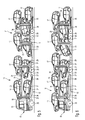
- the articulated trains shown in FIGS. 1 to 8 consists of a motor vehicle (car transporter) 10 and a trailer 11.
- the motor vehicle 10 and trailer 11 each have a lower loading level, each through the frame 12 of the motor vehicle 10 and the frame 13th the trailer 11 are formed.
- a second, upper loading level 14 or 15 is respectively arranged vertically adjustable on upright supports 16.
- a load of passenger cars 17 and in Fig. 8 a load with (small) truck 18 is shown.
- the shown articulated trains have in common that the motor vehicle 10 is behind a cab 19, possibly with driver's cab 20, arranged centerpiece 21 of the frame 12 of the motor vehicle 10 is lowered relative to the normal vehicle frame of a conventional truck.
- Fig. 1 is a front piece 22 above the front axle 23 and a rear piece 24 above the rear axle 25 and thus on the plane normal vehicle frame of a conventional truck.
- the frame 12 is bent downwards (offsets 26, 27) so that the center piece 21 is arranged lower than the front piece 22 and the rear piece 24.
- FIGS. 1 to 8 further show that the motor vehicle 10 is longer and the trailer 11 is correspondingly shorter than a motor vehicle otherwise used as a motor vehicle in car transport articulated trains. This is an additional measure that facilitates the achievement of the cheaper load. This measure is not mandatory. Rather, the selection of a suitable ratio of lengths between the towing vehicle 10 and trailer 11 will depend essentially on whether small cars, mid-range cars or cars of the upper class are to be transported on the articulated train.
- the center piece 21 can also be designed as a slope sloping down to the front axle or the rear axle with only one bend.
- the stage 28 can be pivoted downwardly, as shown in Figs. 3 to 7.
- the rear (the rear axle 25 facing) can be pivoted down to a level below the actual frame plane.
- the rear end is pivoted even below the plane of the axes 23, 25 down to a plane corresponding to the underside of the lowered center piece 21, down.
- the front stage 30 in the upper deck 14 on the towing vehicle 10 is pivotally mounted at its rear end. Likewise, the rear stage 31st
- the towing vehicle 10 facing stage 32 at its rear end to a spindle on the front support 16 of the trailer 11 can be raised and lowered mounted and by means of a hydraulic cylinder (not shown) in a vertical plane.
- the further stage 33 is pivotally mounted with its front end to a wheel arch 39 for a tandem axle 40 of the trailer and the still underlying stage 34 at its rear end on the frame 13, with its front end behind the wheel arch 39 can be pivoted downwards.
- the front end does not protrude forward beyond the rear end of the wheel arch 39.
- two stages 35 and 36 are arranged one behind the other pivotally, namely the front stage 35 at its front end and the rear stage 36 approximately in its center.
- FIGS. 1 to 5, 7 and 8 respectively show the same articulated cable, namely with a motor vehicle 10 with driver's sleeping compartment 20, in different loading variants.
- Fig. 6 shows a articulated train with a towing vehicle 10 without driver's cab, which is loaded with the same vehicles as shown in Fig. 5.
- Fig. 1 shows concretely a so-called six-load, so loaded with six passenger cars 17 articulated train.
- the passenger cars 17 are minivans.
- the stage 28 is pivoted to its lowest position.
- Fig. 2 shows the articulated cable during loading or unloading.
- the stage 28 is pivoted to horizontal position.
- the arranged behind the stage 29 is pivoted so and the sliding element 38 moved backwards that results from the stage 32 on the stage 29, a "roadway" to the stage 29.
- Fig. 3 shows an eight-way with Kombipersonenwagen 17 middle class, being transported on the motor vehicle four passenger cars 17.
- two sedans are transported instead of a station wagon on the lower frame 14 of the trailer, so that there is a Neunerbeladung here.
- loaded on stage 28 passenger car 17 is loaded backward than with the Rear to the cab 19.
- the stage 28 is pivoted down to its lowest position.
- the passenger car loaded behind the platform 29 is loaded forward and the sliding element 38 is moved forward when the platforms 29 are pivoted upwards.
- the front of the transported on the stage 29 passenger car 17 is thereby arranged partially over the front of the passenger car 17 on the stage 28.
- Fig. 5 shows a nine-load with passenger cars 17 the size of an Opel Corsa®.
- four passenger cars 17 are loaded on the motor vehicle 10 (four-load) and five passenger cars 17 on the trailer 11 (five-load).
- the stage 28 is pivoted down to its lowest position. Compared to a conventional load so only nine passenger cars 17 are transported in the embodiments of FIG. 3 to 5, however, an additional vehicle on the towing vehicle 10th
- Fig. 7 shows a figure eight with Kombipersonenwagen 17 of the upper class.
- the stage 28 is again pivoted to its lowermost position, the loaded on her car 17 back and loaded on the stage 29 behind passenger cars 17 is loaded forward. Their front cars overlap again (see also the loading variants according to FIGS. 3 and 4).
- Fig. 8 shows the sake of completeness still a load of four pickup trucks 18th
- FIGS. 9 to 10 show how an articulated cable according to the invention can advantageously be loaded:
- the stage 32 on the frame of the trailer 11 serves as a ramp, so that a separate charging rail is not required.
- the upper loading level 14 of the motor vehicle is now moved up to its desired position for transport.
- two, passenger cars 17 can be loaded onto the frame 12 or its platforms 28 and 29 (FIG. 10).
- the stage 28 is lowered with its rear end, as described above, wherein in Fig. 10 to 12 also serving for this pressure cylinder 41 can be seen.
- the upper deck 15 of the trailer 11 is lowered and loaded on the frame 13 (FIG. 11).
- the passenger cars 17 are lashed again at lowered upper deck level 15.
- the towing vehicle 10 of the embodiment of FIGS. 13 and 14 differs from the towing vehicle 10 of the embodiments described above in that the stage 28 is divided by a hinge 42 into a cab-side section 43 and a rear-axle-side section 44. At the upper loading level 14, the stage 30 has a gap 45. Rails 46 are provided only in the front, the cab 19 facing area. To accommodate the rear wheels of the vehicle 30 to be loaded on the vehicle to be used transversely extending and longitudinally of the stage 30 slidably arranged rods 47th
- the rear-axle-side portion 44 of the lower stage 28 closes the gap 45.
- the cab side section 43 is pivoted upwards and at the same time the hinterachs workede Section 44 brought into a horizontal position.
- a vehicle 17 can now be driven onto the platform 30 until the front wheels reach the rails 46.
- the rear wheels are received between the rods 47, which may have previously been adjusted to the appropriate position. Alternatively, it is also possible to bring the rods 47 now in their required for the transport of the vehicle 17 position.
- FIG. 14 shows the already loaded motor vehicle 10.
- the stage 28 is here pivoted to a position in which the cab side section 43 of the stage 28 is arranged approximately horizontally.
- the rear axle-side section 44 bends downwards, wherein the rear-axle-side end of the rear axle-side section 44 is arranged approximately at the level of the lower edge of the lowered center piece 21.
Abstract
Description
Die Erfindung betrifft einen Autotransporter mit einem Führerhaus und mit einem von einer Vorderachse und einer Hinterachse getragenen Rahmen, an welchem eine Bühne für Fahrzeuge angeordnet ist, welche zwischen der Vorderachse und der Hinterachse angeordnet sowie an ihrem dem Führerhaus zugewandten Ende schwenkbar gelagert und mit ihrem der Hinterachse zugewandten Ende absenkbar ist. Ein Transporter dieser Art ist aus der
Ein weiterer Autotransporter diese Art ist aus der
Aus der
Einen in der Praxis wohl kaum zu realisierenden Autotransporter zeigt die
Aus der
Schließlich zeigt die
Die maximale Länge, maximale Breite und maximale Höhe des Gelenkzuges ist aufgrund straßenverkehrsrechtlicher Bestimmungen begrenzt. Ebenso das maximale Gewicht. Ziel jeden Konstrukteurs für Gelenkzüge zum Transport von Kraftfahrzeugen (Autotransportzug) ist es, innerhalb der gesetzlichen Abmessungen möglichst viele Kraftfahrzeuge unterzubringen. Dabei soll der Autotransportzug möglichst noch flexible mit unterschiedlichen Kraftfahrzeugen (Personenwagen der Oberklassen, der Mittelklasse, Kleinwagen, Vans u.s.w.) belanden werden können. Wie viele Fahrzeuge geladen werden können, hängt selbstverständlich immer von der Größe der Fahrzeuge ab. Es ist aber gebräuchlich, Autotransportzüge anhand von zu ladenden Mittelklassewagen auszulegen. Neben der Zahl der transportierbaren Fahrzeuge ist ein weiteres Auslegungskriterium die Lastverteilung auf die Achsen. Dabei ist es oft ein Problem, den Gesamtschwerpunkt der auf dem Motorwagen geladenen Fahrzeuge weit genug nach hinten zu bekommen, also die Vorderachse nicht zu überladen.The maximum length, maximum width and maximum height of the articulated train is limited due to road traffic regulations. Likewise the maximum weight. The aim of every designer of articulated trains for the transport of motor vehicles (car transport train) is to accommodate as many motor vehicles as possible within the statutory dimensions. The autotransport train should be as flexible as possible with different vehicles (passenger cars of the upper classes, middle class, small cars, vans, etc.) can be belanden. Of course, how many vehicles can be loaded depends on the size of the vehicles. However, it is common to design car transport trains on the basis of loading middle class cars. In addition to the number of vehicles that can be transported, another design criterion is the load distribution to the axles. It is often a problem, the center of gravity of loaded on the motor vehicle vehicles far enough to get to the rear, so not overload the front axle.
Auf dem europäischen Kontinent war es bisher nur möglich eine Beladung mit neun Mittelklassewagen zu erreichen. Dieses wird im Wesentlichen durch zwei Varianten erreicht. Nach der ersten Variante wird ein relativ kurzer Motorwagen mit einem entsprechend verlängerten Anhänger eingesetzt. Dabei werden bis zu drei Mittelklassewagen auf dem Motorwagen und bis zu sechs Mittelklassewagen auf dem Anhänger transportiert. Bei der zweiten Variante wird ein relativ langer Motorwagen mit Tandemanhänger verwendet. Der Motorwagen faßt fünf und der Tandemanhänger vier Mittelklassewagen. Es ergibt sich also bei beiden Varianten insgesamt eine Neunerbeladung. Die Dreier bzw. Fünferbeladung auf dem Motorwagen wird für den europäischen Kontinent innerhalb der gesetzlichen Vorgaben nur dadurch erreicht, daß ein Fahrzeug über dem Fahrerhaus des Motorwagens transportiert wird. Das Fahrerhaus kann deshalb nur sehr flach ausgebildet werden. Dieses geht zu Lasten des Komforts für den Fahrer. So bleibt beispielsweise kein Platz für eine Fahrerschlafkabine. Eine solche Fahrerschlafkabine ist aber oft gewünscht, insbesondere auf längeren Fahrten, um den Fahrer die erforderlichen Ruhepausen bequem verbringen zu lassen. Ein geräumiges Führerhaus ist oft auch eine Motivation für den jeweiligen Fahrer und ein gutes Argument bei der Suche nach guten Fahrern, welche schwer zu bekommen und vergleichsweise teuer sind.So far, it has only been possible to reach a load of nine mid-range cars on the European continent. This is achieved essentially by two variants. According to the first variant, a relatively short motor vehicle with a correspondingly extended trailer is used. It will be up to three Middle class car on the towing vehicle and transported up to six middle class cars on the trailer. In the second variant, a relatively long motor vehicle with tandem trailer is used. The motor car holds five and the tandem trailer four middle class cars. This results in both variants a total of nine load. The threefold or five-load on the towing vehicle is achieved for the European continent within the legal requirements only by transporting a vehicle over the driver's cab of the towing vehicle. The cab can therefore be trained only very flat. This is at the expense of comfort for the driver. For example, there is no room for a driver's sleeping cabin. However, such a driver's bed is often desired, especially on longer trips, to let the driver spend the necessary rest periods comfortably. A spacious cab is often also a motivation for the driver and a good argument in the search for good drivers, which are difficult to get and comparatively expensive.
Der Erfindung liegt das Problem zugrunde, einen Autotransporter (Motorwagen) und einen Gelenkzug zu schaffen, auf dem einerseits viele (Personen-)Kraftwagen transportiert werden können und andererseits ein möglichst geräumiges Fahrerhaus, möglichst mit Fahrerschlafkabine, zu schaffen. Dabei kann bei Autotransportern und Gelenkzügen für kurze Strecken die Ladekapazität zu Lasten des Fahrerhauses und, umgekehrt, bei Lastkraftwagen und Gelenkzügen für lange Strecken die Geräumigkeit des Fahrerhaus zu Lasten der Ladekapazität angepaßt sein.The invention is based on the problem to provide a car transporter (towing vehicle) and a articulated train on the one hand many (passenger) cars can be transported and on the other hand to create a spacious as possible cab, possibly with a driver's bed. It can be adapted to the load capacity of the cab and, conversely, in trucks and articulated trains for long distances, the spaciousness of the cab at the expense of loading capacity in car transporters and articulated trains for short distances.
Zur Lösung dieses Problems ist der erfindungsgemäße Autotransporter dadurch gekennzeichnet, daß der Rahmen ein oberhalb einer Vorderachse angeordnetes Vorderstück und ein oberhalb einer Hinterachse angeordnetes Hinterstück sowie ein tiefer als das Vorderstück und Hinterstück angeordnetes Mittelstück aufweist, wobei die Bühne an ihrem dem Führerhaus zugewandten Ende in der Ebene des Vorderstücks schwenkbar gelagert und mit ihrem der Hinterachse zugewandten Ende auf ein Niveau unterhalb des Hinterstücks absenkbar ist. Vorzugsweise ist das der Hinterachse zugewandte Ende der Bühne sogar auf ein Niveau unterhalb der Ebene der Vorder- und Hinterachse, insbesondere bis auf eine Ebene, welche der Unterseite des abgesenkten Mittelstücks entspricht, absenkbar.To solve this problem, the car transporter according to the invention is characterized in that the frame has a front piece arranged above a front axle and a rear piece arranged above a rear axle and a center piece arranged lower than the front piece and rear piece, wherein the stage at its end facing the driver's compartment in the Level of the front piece pivotally mounted and with its the rear axle facing the end can be lowered to a level below the rear piece. Preferably, the rear axle facing the end of the stage even to a level below the plane of the front and rear axles, in particular down to a plane corresponding to the underside of the lowered center piece, lowered.
Durch das abgesenkte Mittelstück ist der Bereich des Fahrzeugrahmens des Autotransporters zwischen Führerhaus und Hinterachse gegenüber dem Rahmen serienmäßiger Lkws abgesenkt. Schon hierdurch erhöht sich die Ladekapazität. Durch die schwenkbare Bühne läßt sich das der Hinterachse zugewandte Ende unterhalb der Ebene des Vorder- und Hinterstücks, also unterhalb des Niveaus des normalen Fahrzeugrahmens absenken, so daß diese Ladekapazität auch genutzt werden kann. Vorzugsweise läßt sich die Bühne noch unter dieses Niveau absenken, so daß zusätzliches Ladevolumen frei wird. Zumindest das auf dieser Bühne transportierte Fahrzeug kann auf einer abgesenkten Ebene transportiert werden, so daß sich über diesem Fahrzeug weitere Fahrzeuge entsprechend besser schachteln lassen. Es lassen sich so innerhalb der maximalen Ladehöhe mehr Fahrzeuge transportieren. Dieses kann dazu benutzt werden, ein zusätzliches Fahrzeug zu transportieren oder zur Steigerung des Komforts für den Fahrer ein größeres Fahrerhaus vorzusehen. Ein weiterer Effekt der Erfindung ist, daß, obwohl kein Fahrzeug mehr über dem Fahrerhaus transportiert werden muß, um die gebräuchliche Neunerbeladung zu erreichen, dennoch der Gesamtschwerpunkt der geladenen Fahrzeuge auf dem Motorwagen weiter nach hinten kommt, so daß die Vorderachse nicht überladen wird.The lowered center piece of the vehicle frame of the car transporter between the cab and rear axle is lowered relative to the frame of standard trucks. This already increases the loading capacity. Due to the pivoting stage, the rear axle facing the end below the level of the front and rear piece, ie below the level of the Lower normal vehicle frame, so that this load capacity can also be used. Preferably, the stage can be lowered even below this level, so that additional loading volume is free. At least the vehicle transported on this stage can be transported on a lowered level, so that it is possible to nest more vehicles accordingly better over this vehicle. It can be transported within the maximum loading height more vehicles. This can be used to transport an additional vehicle or to provide a larger cab for the driver to increase comfort. Another effect of the invention is that although no vehicle needs to be transported over the cab to achieve the usual nine-load, the overall center of gravity of the loaded vehicles on the towing vehicle continues to come back so that the front axle is not overloaded.
Nach einer Weiterbildung der Erfindung ist hinter der Bühne eine weitere Bühne vorgesehen. In diesem Fall ist es vorteilhaft, wenn die zueinander weisenden Enden dieser beiden Bühnen auf ein gemeinsames Niveau bewegbar sind. Hierdurch können beim Be- und Entladen die Fahrzeuge direkt von Bühne zu Bühne gefahren werden, ohne die sonst üblichen "Holperschwellen" über die Hinterachse des Motorwagens.According to a development of the invention, a further stage is provided behind the stage. In this case, it is advantageous if the mutually facing ends of these two stages are movable to a common level. As a result, when loading and unloading the vehicles can be driven directly from stage to stage, without the usual "bumpers" on the rear axle of the motor car.
An einem Autotransporter sind unterschiedliche Anbauteile, wie beispielsweise Tankanlage, Batteriekasten oder Staufächer, angeordnet. Um für diese Anbauteile einen ausreichenden Platz zu schaffen, ist nach einer Weiterbildung der Erfindung vorgesehen, die vordere Bühne auf der unteren Ladeebene durch ein Gelenk in einen führerhausseitigen und einen hinterachsseitigen Abschnitt zu unterteilen. Der führerhausseitige Abschnitt wird während des Transports eines Fahrzeuges in eine etwa horizontale Position geschwenkt, während der hinterachsseitige Abschnitt nach unten geschwenkt wird. Unter dem führerhausseitigen Abschnitt entsteht so ausreichend Platz für die Anbauteile. Das Gelenk kann dabei so weit hinten angeordnet sein, daß es den Boden eines zu ladenden Fahrzeuges gerade nicht berührt. Die in Transportrichtung gesehen vorderen Räder des zu ladenden Fahrzeugs stehen dabei auf dem führerhausseitigen Abschnitt, während die in Transportrichtung gesehen hinteren Räder des zu transportierenden Fahrzeugs auf dem hinterachsseitigen Abschnitt positioniert sind. Alternativ kann der Freiraum für Anbauteile auch dadurch geschaffen werden, daß die Bühne an ihrem dem Führerhaus zugewandten, schwenkbar gelagerten Ende anhebbar und absenkbar ist. Dieses kann auch zusätzlich zu der mittels Gelenk in zwei Abschnitte teilten Bühne eingesetzt werden, um den Freiraum für Anbauteile weiter zu vergrößern.On a car transporter different attachments, such as tank, battery box or storage compartments are arranged. In order to provide sufficient space for these attachments, according to a development of the invention is intended to divide the front stage on the lower deck level by a hinge in a cab-side and a rear-axle-side section. The cab-side section is pivoted during transport of a vehicle in an approximately horizontal position, while the rear-axle-side section is pivoted downward. Under the driver's cab side section so sufficient space for the attachments. The joint can be arranged so far back that it just does not touch the bottom of a vehicle to be loaded. The front wheels of the vehicle to be loaded, viewed in the transporting direction, stand on the driver's cab-side section, while the rear wheels of the vehicle to be transported, as viewed in the transporting direction, are positioned on the rear axle-side section. Alternatively, the space for attachments can also be created by the fact that the stage at its the cab facing, pivotally mounted end can be raised and lowered. This can also be used in addition to the joint divided into two sections stage to further increase the free space for attachments.
Die vorstehend genannte, mit dem Gelenk versehene Bühne läßt sich vorteilhaft für eine weitere Gewichts- und Kostenreduktion des erfindungsgemäßen Autotransporters einsetzen. An einer oberen Ladeebene kann so nämlich in einer Schiene für ein auf diese Ladeebene zu transportierendes Fahrzeug eine Lücke vorgesehen sein. Hierdurch wird Schienenmaterial und damit letztlich Gewicht und Kosten eingespart. Während ein Fahrzeug auf die obere Ladeebene geladen wird, wird diese Lücke durch den hinterachsseitigen Abschnitt der unteren Bühne geschlossen, so daß ein Fahrzeug problemlos auf die obere Ladeebene geladen werden kann.The abovementioned jointed platform can be advantageously used for a further weight and cost reduction of the car transporter according to the invention. At an upper loading level, a gap can thus be provided in a rail for a vehicle to be transported onto this loading level. As a result, rail material and thus ultimately weight and cost savings. While a vehicle is being loaded onto the upper deck, this gap is closed by the rear deck section of the lower stage so that a vehicle can be easily loaded onto the upper deck.
Für den Fall, daß in dem Bereich der Lücke Räder einer Achse des in diesem Bereich geladenen Fahrzeugs während des Transports positioniert sind, sind nach einer Weiterbildung quer verlaufende Stangen vorgesehen, zwischen welchen diese Räder während des Transports gelagert sind. Auch mit den Stangen ergibt sich gegenüber durchlaufenden Schienen eine Gewichtsreduktion. Quer verlaufende Stangen können auch beliebigen anderen, geeigneten Ladepositionen für zu transportierende Fahrzeuge vorgesehen sein, was das Gewicht des Autotransporters weiter reduziert.In the event that in the region of the gap wheels of an axle of the vehicle loaded in this area are positioned during transport, according to a further development transversely extending rods are provided, between which these wheels are stored during transport. Even with the rods is compared to continuous rails, a weight reduction. Transverse rods can also be provided in any other suitable loading positions for vehicles to be transported, which further reduces the weight of the car carrier.
Nach einer konstruktiven Ausgestaltung der Erfindung kann die Bühne an ihrem dem Führerhaus zugewandten, schwenkbaren Ende anhebbar und absenkbar sein.According to a structural embodiment of the invention, the stage at its the cab, facing pivotable end can be raised and lowered.
Ein das der Erfindung zugrunde liegende Problem lösender Gelenkzug weist einen Autotransporter mit den Erfindungsmerkmalen auf.An object of the invention underlying problem-releasing articulated has an auto transporter with the invention features.
Die Erfindung wird nachfolgend anhand eines in der Zeichnung dargestellten Ausführungsbeispiels näher erläutert. Es zeigt:
- Fig. 1
- ein erstes Ausführungsbeispiel für einen Gelenkzug mit den Erfindungsmerkmalen in Seitenansicht in einer erste Beladungsvariante,
- Fig. 2
- den Gelenkzug gemäß Fig. 1 in Seitenansicht während des Beladens,
- Fig. 3.
- den Gelenkzug gemäß Fig. 1 in Seitenansicht in einer zweiten Beladungsvariante,
- Fig. 4
- den Gelenkzug gemäß Fig. 1 in Seitenansicht in einer dritten Beladungsvariante,
- Fig. 5
- den Gelenkzug gemäß Fig. 1 in Seitenansicht in einer vierten Beladungsvariante,
- Fig. 6
- ein zweites Ausführungsbeispiel für einen Gelenkzug mit den Erfindungsmerkmalen in Seitenansicht in einer Beladungsvariante mit Fahrzeugen wie der Gelenkzug gemäß Fig. 5,
- Fig. 7
- den Gelenkzug gemäß Fig. 1 in Seitenansicht in einer fünften Beladungsvariante,
- Fig.8
- den Gelenkzug gemäß Fig. 1 in Seitenansicht in einer weiteren Beladungsvariante,
- Fig. 9
- einen ersten Belandungsschritt für einen Gelenkzug mit den Erfindungsmerkmalen,
- Fig. 10
- einen zweiten Beladungsschritt für den Gelenkzug gemäß Fig. 9,
- Fig. 11
- einen dritten Beladungsschritt für den Gelenkzug gemäß Fig. 9,
- Fig. 12
- einen weiteren Beladungsschritt für den Gelenkzug gemäß Fig. 9,
- Fig. 13
- ein weiteres Ausführungsbeispiel für einen Gelenkzug mit den Erfindungsmerkmalen in Seitenansicht in teilbeladenem Zustand,
- Fig. 14
- den Gelenkzug gemäß Fig. 13 mit vollständig beladenem Motorwagen,
- Fig. 15
- eine obere Ladeebene des Motorwagens des Gelenkzugs gemäß Fig. 13 in Draufsicht.
- Fig. 1
- A first embodiment of a articulated train with the features of the invention in side view in a first loading variant,
- Fig. 2
- the articulated cable according to FIG. 1 in side view during loading,
- Fig. 3.
- 1 in side view in a second loading variant,
- Fig. 4
- the articulated train according to FIG. 1 in a side view in a third loading variant,
- Fig. 5
- 1 in side view in a fourth loading variant,
- Fig. 6
- a second embodiment of a articulated train with the features of the invention in side view in a loading variant with vehicles such as the articulated according to FIG. 5,
- Fig. 7
- the articulated train according to FIG. 1 in a side view in a fifth loading variant,
- Figure 8
- 1 in side view in a further loading variant,
- Fig. 9
- a first loading step for a articulated train with the inventive features,
- Fig. 10
- a second loading step for the articulated cable according to FIG. 9,
- Fig. 11
- a third loading step for the articulated cable according to FIG. 9,
- Fig. 12
- a further loading step for the articulated cable according to FIG. 9,
- Fig. 13
- a further embodiment of a hinge with the features of the invention in side view in teilbeladenem condition,
- Fig. 14
- the articulated cable according to FIG. 13 with the motor vehicle completely loaded,
- Fig. 15
- an upper loading level of the motor vehicle of the articulated according to FIG. 13 in plan view.
Die in den Fig. 1 bis 8 gezeigten Gelenkzüge besteht aus einem Motorwagen (Autotransporter) 10 und einem Anhänger 11. Der Motorwagen 10 und Anhänger 11 weisen jeweils eine untere Ladeebene auf, die jeweils durch den Rahmen 12 des Motorwagens 10 bzw. den Rahmen 13 des Anhängers 11 gebildet sind. Oberhalb der Rahmen 12, 13 wird jeweils eine zweite, obere Ladeebene 14 bzw. 15 an aufrechten Stützen 16 höhenverstellbar angeordnet. In Fig. 1 bis 7 ist eine Beladung mit Personenwagen 17 und in Fig. 8 eine Beladung mit (Klein-)Lastwagen 18 gezeigt.The articulated trains shown in FIGS. 1 to 8 consists of a motor vehicle (car transporter) 10 and a
Den gezeigten Gelenkzügen ist gemeinsam, daß beim Motorwagen 10 ein hinter einem Führerhaus 19, ggf. mit Fahrerschlafkabine 20, angeordnetes Mittelstück 21 des Rahmens 12 des Motorwagens 10 gegenüber dem normalen Fahrzeugrahmen eines herkömmlichen Lastkraftwagens abgesenkt ist. Wie in Fig. 1 erkennbar befindet sich ein Vorderstück 22 oberhalb der Vorderachse 23 und ein Hinterstück 24 oberhalb der Hinterachse 25 und damit auf der Ebene normaler Fahrzeugrahmen eines herkömmlichen Lastkraftwagens. Hinter der Vorderachse 23 bzw. vor der Hinterachse 25 ist der Rahmen 12 jedoch nach unten abgekröpft (Abkröpfungen 26, 27), so daß das Mittelstück 21 tiefer angeordnet ist, als das Vorderstück 22 und das Hinterstück 24.The shown articulated trains have in common that the
Den Fig. 1 bis 8 ist weiterhin zu entnehmen, daß der Motorwagen 10 gegenüber einem sonst als Motorwagen in Autotransport-Gelenkzügen verwendeten Motorwagen länger und der Anhänger 11 entsprechend kürzer ausgebildet ist. Dieses ist eine zusätzliche Maßnahme, die das Erreichen der günstigeren Beladung erleichtert. Diese Maßnahme ist aber nicht zwingend. Vielmehr wird die Auswahl eines geeigneten Längenverhältnisses zwischen Motorwagen 10 und Anhänger 11 im wesentlichen davon abhängen, ob auf dem Gelenkzug Kleinwagen, Mittelklassewagen oder Wagen der Oberklasse transportiert werden sollen.FIGS. 1 to 8 further show that the
Alternativ zur oben beschriebenen Absenkung des Mittelstücks 21 durch die Abkröpfungen 26 und 27 kommt auch jede andere Absenkung in Betracht. So kann das Mittelstück beispielsweise auch als zur Vorderachse oder zur Hinterachse abfallende Schräge mit nur einer Abkröpfung ausgebildet sein.As an alternative to the above-described lowering of the
An den Rahmen 12, 13 und/oder an den oberen Ladeebenen 14, 15 sind schwenkbare Bühnen 28, 29, 30, 31, 32, 33, 34, 35, 36 angeordnet, durch die sich beladene Personenkraftwagen 17 zusätzlich verschwenken lassen, um so zu einer möglichst dichten Schachtelung von Personenkraftwagen 17 zu kommen. Die Bühne 28, welche auf am Motorwagen 10 auf der unteren Ladeebene zwischen der Vorderachse 23 und der Hinterachse 25 angeordnet ist, ist an ihrem vorderen (dem Führerhaus 19 zugewandten) Ende schwenkbar am Rahmen 12 angebracht. Die Bühne 28 kann nach unten geschwenkt werden, wie dieses in den Fig. 3 bis 7 gezeigt ist. Konkret kann das hintere (der Hinterachse 25 zugewandte) nach unten auf ein Niveau unterhalb der eigentliche Rahmeneben geschwenkt werden. Wie den Fig. 3 bis 7 zu entnehmen ist, wird das hintere Ende sogar noch unterhalb der Ebene der Achsen 23, 25 bis auf eine Ebene, die der Unterseite des abgesenkten Mittelstücks 21 entspricht, nach unten geschwenkt.On the
Die Bühne 29, welche am Motorwagen 10 auf der unteren Ladeebene hinter der Bühne 28, etwa oberhalb der Hinterachse 25 angeordnet ist, ist zweiteilig ausgebildet, nämlich mit einem Schwenkrahmen 37 und Schiebeelement 38, welches am Schwenkrahmen 37 in Längsrichtung des Gelenkzuges hin- und herfahrbar angeordnet ist.The
Die vordere Bühne 30 in der oberen Ladeebene 14 am Motorwagen 10 ist an ihrem hinteren Ende schwenkbar angebracht. Ebenso die hintere Bühne 31.The
Am Anhänger 11 ist eine vordere, dem Motorwagen 10 zugewandte Bühne 32 an ihrem hinteren Ende an einer Spindel an der vorderen Stütze 16 des Anhängers 11 heb- und senkbar angebracht und mittels eines Hydraulikzylinders (nicht dargestellt) in einer vertikalen Ebene schwenkbar. Die weitere Bühne 33 ist mit ihrem vorderen Ende an einem Radkasten 39 für eine Tandemachse 40 des Anhängers schwenkbar befestigt und die noch dahinter liegende Bühne 34 an ihrem hintern Ende am Rahmen 13, wobei ihr vorderes Ende hinter dem Radkasten 39 nach unten geschwenkt werden kann. Das vordere Ende ragt also nach vorn nicht über das hintere Ende des Radkastens 39 hinaus.On the
An der oberen Ladeebene 15 des Anhängers 11 sind zwei Bühnen 35 und 36 hintereinander schwenkbar angeordnet, und zwar die vordere Bühne 35 an ihrem vorderen Ende und die hintere Bühne 36 etwa in ihrer Mitte.At the
Es sind also insgesamt neun schwenkbare Bühnen 28..36 vorgesehen, also beim Gelenkzug gemäß Fig. 1 bis 5, 7 und 8 für jeden ladbaren Personenwagen 17 eine Bühne 28..36.So there are a total of nine swivel stages 28..36 provided, so in the articulated train of FIG. 1 to 5, 7 and 8 for each loadable passenger 17 a
In den Fig. 1 bis 5, 7 und 8 ist jeweils der selbe Gelenkzug, nämlich mit einem Motorwagen 10 mit Fahrerschlafkabine 20, in unterschiedlichen Beladungsvarianten gezeigt. Fig. 6 zeigt einen Gelenkzug mit einem Motorwagen 10 ohne Fahrerschlafkabine, der mit den selben Fahrzeugen wie in Fig. 5 gezeigt, beladen ist.FIGS. 1 to 5, 7 and 8 respectively show the same articulated cable, namely with a
Fig. 1 zeigt konkret eine sogenannte Sechserbeladung, also einen mit sechs Personenkraftwagen 17 beladenen Gelenkzug. Bei den Personenwagen 17 handelt es sich um Minivans. Die Bühne 28 ist auf ihre unterste Stellung geschwenkt.Fig. 1 shows concretely a so-called six-load, so loaded with six
Fig. 2 zeigt den Gelenkzug während des Be- bzw. Endladens. Die Bühne 28 ist in horizontale Stellung geschwenkt. Die dahinter angeordnete Bühne 29 ist so geschwenkt und das Schiebeelement 38 nach hinten gefahren, daß sich von der Bühne 32 über die Bühne 29 eine "Fahrbahn" zur Bühne 29 ergibt.Fig. 2 shows the articulated cable during loading or unloading. The
Fig. 3 zeigt eine Achterbeladung mit Kombipersonenwagen 17 der Mittelklasse, wobei auf dem Motorwagen vier Personenwagen 17 transportiert werden. In Fig. 4 werden auf dem unteren Rahmen 14 des Anhängers zwei Limousinen anstelle eines Kombis befördert, so daß sich hier eine Neunerbeladung ergibt. In beiden Fällen ist der auf der Bühne 28 geladen Personenwagen 17 rückwärts geladen, als mit dem Heck zum Führerhaus 19. die Bühne 28 ist auf ihre unterste Stellung nach unten geschwenkt. Der auf der Bühne 29 dahinter geladene Personenwagen ist vorwärts geladen und das Schiebeelement 38 bei nach oben geschwenkter Bühnen 29 nach vorn verfahren. Der Vorderwagen des auf der Bühne 29 transportierten Personenwagens 17 ist dadurch zum Teil über dem Vorderwagen des Personenwagens 17 auf der Bühne 28 angeordnet.Fig. 3 shows an eight-way with
Fig. 5 zeigt eine Neunerbeladung mit Personenwagen 17 der Größe eines Opel Corsa®. Dabei sind wieder vier Personenkraftwagen 17 auf dem Motorwagen 10 (Viererbeladung) und fünf Personenkraftwagen 17 auf dem Anhänger 11 (Fünferbeladung) geladen. Die Bühne 28 ist auf ihre unterste Stellung nach unten geschwenkt. Gegenüber einer herkömmlichen Beladung werden bei den Ausführungsbeispielen gemäß Fig. 3 bis 5 also auch nur neun Personenkraftwagen 17 befördert, jedoch ein zusätzliches Fahrzeug auf dem Motorwagen 10.Fig. 5 shows a nine-load with
Gegenüber einer herkömmlichen Beladung ist oberhalb eines Führerhauses 19 kein Fahrzeug 17 angeordnet, so daß das Führerhaus 19 erhöht und so mit der zusätzlichen Fahrerschlafkabine 20 ausgerüstet werden kann. Durch entsprechend andere Schachtelungen der Personenkraftwagen 17 läßt es sich bei entsprechend niedrigerem ("normalen") Führerhaus auch erreichen, daß fünf Personenwagen 17 auf dem Motorwagen 10 transportiert werden können, so daß sich insgesamt eine Zehnerbeladung ergibt (Fig. 6). Die Bühne 28 kann dabei in horizontaler Stellung bleiben.Compared to a conventional load, no
Fig. 7 zeigt eine Achterbeladung mit Kombipersonenwagen 17 der Oberklasse. Die Bühne 28 ist wieder in ihre unterste Stellung geschwenkt, wobei der auf ihr geladene Personenwagen 17 rückwärts und der auf der Bühne 29 dahinter geladene Personenwagen 17 vorwärts geladen ist. Ihre Vorderwagen überlappen sich wieder (vgl. auch die Beladungsvarianten gemäß Fig. 3 und 4).Fig. 7 shows a figure eight with
Fig. 8 zeigt der Vollständigkeit halber noch eine Beladung mit vier Kleinlastwagen 18.Fig. 8 shows the sake of completeness still a load of four pickup trucks 18th
Bei genauer Betrachtung der Fig. 1 bis 8 erkennt man, daß für ein optimales Verschachteln der Personenwagen 17 bzw. Kleinlastwagen 18 nicht nur die Bühnen 28..36 verschwenkt, sondern auch die oberen Ladeebenen 14, 15 in ihre Höhe eingestellt und teilweise auch schräg gestellt werden.Upon closer inspection of Figs. 1 to 8 it can be seen that for optimal nesting of the
In den Figuren 9 bis 10 ist gezeigt, wie ein erfindungsgemäßer Gelenkzug vorteilhaft beladen werden kann:FIGS. 9 to 10 show how an articulated cable according to the invention can advantageously be loaded:
Fig. 9 zeigt zunächst, wie die obere Ladeebene 14 des Motorwagens 10 beladen wird. Die obere Ladeebene 14 ist an den Stützen 16 soweit abgesenkt, daß sie auf dem Rahmen 12 aufliegt. Nun werden im vorliegenden Fall zwei Personenwagen 17 auf die obere Ladeebene 14 über den Anhänger 11 gefahren. Die Personenwagen 17 fahren dabei über den Rahmen 13 des Anhängers 11 unter dessen obere Ladeebene 15 hindurch. Die Bühne 32 am Rahmen des Anhängers 11 dient hier als Überfahrrampe, so daß eine gesonderte Ladeschiene nicht erforderlich ist.9 initially shows how the
Die so auf die obere Ladeebene 14 des Motorwagens 10 geladenen Personenwagen 17 können nun von einer Bedienperson bequem neben dem Motorwagen 10 stehend verzurrt werden. Die Bedienperson braucht nicht mehr auf dem Motorwagen "herumturnen", was die Sicherheit, insbesondere bei Regen, Eis und Schnee, erhöht. Da die Bedienperson auch nicht mehr auf dem Motorwagen 10 zwischen den geladenen Personenwagen 17 und einem oft vorhandenen Geländer auf der obere Ladeebene 14 entlanggehen muß, ist die Gefahr eines Verkratzen oder sonstigen Beschädigen der Personenwagen 17, beispielsweise durch (an sich verbotene) Uhren, Ringe oder dergleichen, vermieden.The loaded so on the
Die obere Ladeebene 14 des Motorwagens wird nun in ihre für den Transport gewünschte Position nach oben gefahren. Jetzt können in analoger Weise, im vorliegenden Fall zwei, Personenwagen 17 auf den Rahmen 12, bzw. dessen Bühnen 28 und 29 geladen werden (Fig. 10). Die Bühne 28 wird mit ihrem hinteren Ende, wie oben beschrieben, abgesenkt, wobei in Fig. 10 bis 12 auch der hierfür dienende Druckmittelzylinder 41 erkennbar ist.The
Nun wird die obere Ladeebene 15 des Anhängers 11 auf dessen Rahmen 13 abgesenkt und beladen (Fig. 11). Die Personenwagen 17 werden wieder bei abgesenkter oberer Ladeebene 15 verzurrt.Now, the
Schließlich wird die obere Ladeebene 15 des Anhängers 11 in die für den Transport gewünschte Stellung nach oben verfahren und die untere Ladeebene (Rahmen 13) des Anhängers beladen (Fig. 12).Finally, the
Bei dieser Art des Beladens des Gelenkzuges sind also keine zusätzlichen Ladeschienen erforderlich. Der Gelenkzug läßt sich vollständig unter Verwendung der vorhandenen Bühnen 28..36 beladen. Ein manuelles Ein- und Ausrichten zusätzlicher Schienen entfällt Es ergeben sich insgesamt flache Überfahrten für die Personenwagen 17, ohne das sonst oft vorhandene Holpern und Springen der Personenwagen 17, sowie flache Auf- und Überfahrtswinkel.In this type of loading the articulated train so no additional charging rails are required. The articulated cable can be fully loaded using the existing
Der Motorwagen 10 des Ausführungsbeispiels gemäß Fig. 13 und 14 unterscheidet sich vom Motorwagen 10 der vorstehend beschriebenen Ausführungsbeispiele dadurch, daß die Bühne 28 durch ein Gelenk 42 in einen führerhausseitigen Abschnitt 43 und einen hinterachsseitigen Abschnitt 44 unterteilt ist. An der oberen Ladeebene 14 weist die Bühne 30 eine Lücke 45 auf. Schienen 46 sind nur in dem vorderen, dem Führerhaus 19 zugewandten Bereich vorgesehen. Zur Aufnahme der Hinterräder des auf die Bühne 30 zu ladenden Fahrzeugs dienen quer verlaufende und in Längsrichtung der Bühne 30 verschieblich angeordnete Stangen 47.The towing
Um ein Fahrzeug 17 auf die Bühne 30 der oberen Ladeebene 40 laden zu können, schließt, wie in Fig. 13 gezeigt, der hinterachsseitige Abschnitt 44 der unteren Bühne 28 die Lücke 45. Hierzu wird der führerhausseitige Abschnitt 43 nach oben geschwenkt und gleichzeitig der hinterachsseitige Abschnitt 44 in eine horizontale Lage gebracht. Ein Fahrzeug 17 kann nun auf die Bühne 30 aufgefahren werden, bis die Vorderräder auf die Schienen 46 gelangen. Die Hinterräder werden zwischen den Stangen 47 aufgenommen, welche bereits vorher auf die entsprechende Position eingestellt worden sein können. Alternativ ist es auch möglich, die Stangen 47 jetzt in ihre zum Transport des Fahrzeugs 17 erforderliche Position zu bringen.To load a
Nachdem die obere Ladeebene 14 mit Fahrzeugen beladen ist, wird sie, wie bereits vorstehend beschrieben, in ihre obere, in Fig. 14 gezeigte Position gebracht. Nun kann die untere Ladeebene (Rahmen 12) beladen werden. Fig. 14 zeigt den bereits beladenen Motorwagen 10. Die Bühne 28 ist hier in eine Position geschwenkt, bei der der führerhausseitige Abschnitt 43 der Bühne 28 in etwa horizontal angeordnet ist. Am Gelenk 42 knickt der hinterachsseitige Abschnitt 44 nach unten ab, wobei das hinterachsseitige Ende des hinterachsseitigen Abschnitts 44 etwa auf der Ebene der Unterkante des abgesenkten Mittelstücks 21 angeordnet ist.After the
- 1010
- Motorwagenmotor car
- 1111
- Anhängerpendant
- 1212
- Rahmenframe
- 1313
- Rahmenframe
- 1414
- Ladeebeneload level
- 1515
- Ladeebeneload level
- 1616
- Stützesupport
- 1717
- PersonenkraftwagenPassenger cars
- 1818
- Lastwagentruck
- 1919
- Führerhauscabin
- 2020
- FahrerschlafkabineDriver's sleeping cabin
- 2121
- Mittelstückcenterpiece
- 2222
- Vorderstückfront piece
- 2323
- VorderachseFront
- 2424
- Hinterstückbehind piece
- 2525
- Hinterachserear axle
- 2626
- Abkröpfungbend
- 2727
- Abkröpfungbend
- 2828
- Bühnestage
- 2929
- Bühnestage
- 3030
- Bühnestage
- 3131
- Bühnestage
- 3232
- Bühnestage
- 3333
- Bühnestage
- 3434
- Bühnestage
- 3535
- Bühnestage
- 3636
- Bühnestage
- 3737
- Schwenkrahmenswing frame
- 3838
- Schiebeelementsliding element
- 3939
- Radkastenwheel well
- 4040
- Tandemachsetandem axle
- 4141
- DruckmittelzylinderPressure cylinder
- 4242
- Gelenkjoint
- 4343
- Abschnittsection
- 4444
- Abschnittsection
- 4545
- Lückegap
- 4646
- Schienerail
- 4747
- Stangepole
Claims (10)
- Haulaway comprising a truck cabin (19) and a frame (12) supported by a front axle (23) and a rear axle (25), on which a platform (28) for vehicles (17, 18) is disposed that is arranged between said front axle (23) and said rear axle (25) and supported for a pivoting movement at its end facing said truck cabin (19) and for being lowered at its end facing said rear axle (25), characterised in that said frame (12) comprises a front section (22) disposed above a front axle (23), a rear section (24) disposed above a rear axle (25) as well as a central section (21) disposed lower than said front section (22) and said rear section (24), with said platform (28) being supported for a pivoting movement in the plane of said front section (22) at its end facing said truck cabin (19) and being adapted for being lowered to a level below said rear section (24) at its end facing said rear axle (25).
- Haulaway according to Claim 1, characterised in that said platform (28) is adapted to be lowered, at its end facing said rear axle (25), to a level below the plane of said axles (23, 25).
- Haulaway according to Claim 2, characterised in that said platform (28) is adapted to be lowered, at its end facing said rear axle (25), to a plane corresponding to the bottom side of the lowered central section.
- Haulaway according to any of the Claims 1 to 3, characterised in that a further platform (29) is arranged behind said platform (28) for a further vehicle (17, 18), with the ends of said platforms (28, 29) directed to each other being adapted to be moved to a common level.
- Haulaway according to any of the Claims 1 to 4, characterised in that said platform (28) is subdivided by a hinge (42) into a truck cabin side segment (43) and a rear axle segment (44).
- Haulaway according to Claim 5, characterised in that a gap (45) without rails for vehicles to be loaded (17) is provided in an upper cargo plane (14), and that said gap (45) is closed by one of said segments (43, 44) of said platform (28) during the operation of loading onto said upper cargo plane (14).
- Haulaway according to any of the Claims 1 to 6, characterised in that wheels of a rear axle and/or front axle of at least one of the vehicles to be carried (17, 18) are supported in transport between transversely extending rods (47).
- Haulaway according to Claim 7, characterised in that said rods (47) are disposed for displacement along the longitudinal extension of the haulaway.
- Haulaway according to any of the Claims 1 to 8, characterised in that said platform (28) is adapted to be raised and lowered at its end supported for a pivoting movement and facing said truck cabin (19).
- Articulated train including a haulaway (10) according to any of the Claims 1 to 9 and a trailer (11).
Priority Applications (1)
| Application Number | Priority Date | Filing Date | Title |
|---|---|---|---|
| PL05111090T PL1661756T3 (en) | 2004-11-24 | 2005-11-22 | Cars transporting vehicle and such a vehicle combined with a trailer |
Applications Claiming Priority (1)
| Application Number | Priority Date | Filing Date | Title |
|---|---|---|---|
| DE102004056825A DE102004056825A1 (en) | 2004-11-24 | 2004-11-24 | Car transporter and articulated train with such a car transporter |
Publications (2)
| Publication Number | Publication Date |
|---|---|
| EP1661756A1 EP1661756A1 (en) | 2006-05-31 |
| EP1661756B1 true EP1661756B1 (en) | 2008-01-16 |
Family
ID=35709180
Family Applications (1)
| Application Number | Title | Priority Date | Filing Date |
|---|---|---|---|
| EP05111090A Not-in-force EP1661756B1 (en) | 2004-11-24 | 2005-11-22 | Cars transporting vehicle and such a vehicle combined with a trailer |
Country Status (5)
| Country | Link |
|---|---|
| EP (1) | EP1661756B1 (en) |
| AT (1) | ATE383969T1 (en) |
| DE (2) | DE102004056825A1 (en) |
| PL (1) | PL1661756T3 (en) |
| RU (1) | RU2350492C2 (en) |
Cited By (7)
| Publication number | Priority date | Publication date | Assignee | Title |
|---|---|---|---|---|
| CN102069743A (en) * | 2010-08-16 | 2011-05-25 | 河南理工大学 | Car carrier |
| CN102139656A (en) * | 2010-11-19 | 2011-08-03 | 靳北彪 | Land aircraft carrier traffic system |
| CN102490642A (en) * | 2011-12-28 | 2012-06-13 | 北京祥龙物流(集团)有限公司 | Vehicle special for road transportation of magnetic suspension train |
| DE202013105403U1 (en) | 2013-11-27 | 2014-12-16 | Sami Kuvvetli | Transport vehicle for motor vehicles |
| EP2878485A2 (en) | 2013-11-27 | 2015-06-03 | Sami Kuvvetli | Transport vehicle for motor vehicles and method for loading them |
| EP2878484A1 (en) | 2013-11-27 | 2015-06-03 | Sami Kuvvetli | Transport vehicle for motor vehicles and method for loading them |
| EP3785988A1 (en) | 2019-08-29 | 2021-03-03 | Kässbohrer Transport Technik GmbH | Vehicle transporter |
Families Citing this family (6)
| Publication number | Priority date | Publication date | Assignee | Title |
|---|---|---|---|---|
| DE102008048089B4 (en) | 2008-09-19 | 2016-03-24 | Allgemeiner Deutscher Automobil-Club (Adac) Niedersachsen/Sachsen-Anhalt E.V. | semitrailer |
| DE202010005277U1 (en) | 2010-04-22 | 2010-09-30 | Grädtke, Gudrun | Transport vehicle, in particular vehicle transporter for cars |
| CN102114801A (en) * | 2011-02-21 | 2011-07-06 | 新康电脑科技(苏州)有限公司 | Centralized service-car carrying system based on highway interval |
| ITAQ20110005A1 (en) * | 2011-05-04 | 2012-11-05 | Silver Car Srl | PIANALINO A RAMP NEGATIVA A THREE FUNCTIONS OR DEGREES OF FREEDOM |
| RS55039B1 (en) * | 2011-06-16 | 2016-12-30 | Rolfo Spa | Loading flatbed for transporting vehicles |
| CN106671857B (en) * | 2017-03-03 | 2023-05-02 | 安吉汽车物流有限公司 | Central axle train for vehicle transportation |
Family Cites Families (8)
| Publication number | Priority date | Publication date | Assignee | Title |
|---|---|---|---|---|
| US2750225A (en) * | 1950-07-06 | 1956-06-12 | Dealers Transit Inc | Automobile transporting vehicle |
| AT243628B (en) * | 1963-10-10 | 1965-11-25 | Rudolf Demelbauer | Car transport trucks |
| FR2187573A1 (en) * | 1972-06-06 | 1974-01-18 | Lohr Sa | |
| IT1078374B (en) * | 1977-01-20 | 1985-05-08 | Rolfo Spa | TRUCK FOR THE TRANSPORT OF MEDIUM AND HEAVY VEHICLES |
| DE8011609U1 (en) * | 1979-05-04 | 1980-07-31 | Farid S.P.A., Moncalieri, Turin (Italien) | VEHICLE FOR THE TRANSPORTATION OF PASSENGER CARS |
| GB2139968A (en) * | 1983-04-29 | 1984-11-21 | York Technical Services Limite | Car transporters |
| FR2635301B1 (en) * | 1988-08-05 | 1990-10-26 | Lohr Ind | ARTICULATED CONVEYOR CAR CARRIERS WITH MOBILE INDIVIDUAL CARRIERS IN COMPOUND MOVEMENTS |
| US6177868B1 (en) * | 2000-06-15 | 2001-01-23 | Daniel R. Hollingsworth | Retractable cargo height sensing system |
-
2004
- 2004-11-24 DE DE102004056825A patent/DE102004056825A1/en not_active Withdrawn
-
2005
- 2005-11-22 PL PL05111090T patent/PL1661756T3/en unknown
- 2005-11-22 EP EP05111090A patent/EP1661756B1/en not_active Not-in-force
- 2005-11-22 DE DE502005002556T patent/DE502005002556D1/en active Active
- 2005-11-22 AT AT05111090T patent/ATE383969T1/en active
- 2005-11-24 RU RU2005136478/11A patent/RU2350492C2/en not_active IP Right Cessation
Cited By (9)
| Publication number | Priority date | Publication date | Assignee | Title |
|---|---|---|---|---|
| CN102069743A (en) * | 2010-08-16 | 2011-05-25 | 河南理工大学 | Car carrier |
| CN102139656A (en) * | 2010-11-19 | 2011-08-03 | 靳北彪 | Land aircraft carrier traffic system |
| CN102490642A (en) * | 2011-12-28 | 2012-06-13 | 北京祥龙物流(集团)有限公司 | Vehicle special for road transportation of magnetic suspension train |
| DE202013105403U1 (en) | 2013-11-27 | 2014-12-16 | Sami Kuvvetli | Transport vehicle for motor vehicles |
| EP2878485A2 (en) | 2013-11-27 | 2015-06-03 | Sami Kuvvetli | Transport vehicle for motor vehicles and method for loading them |
| EP2878484A1 (en) | 2013-11-27 | 2015-06-03 | Sami Kuvvetli | Transport vehicle for motor vehicles and method for loading them |
| EP3785988A1 (en) | 2019-08-29 | 2021-03-03 | Kässbohrer Transport Technik GmbH | Vehicle transporter |
| DE102019123202A1 (en) * | 2019-08-29 | 2021-03-04 | Kässbohrer Transport Technik Gmbh | Vehicle transporters with such a platform |
| DE102019123202B4 (en) * | 2019-08-29 | 2021-05-27 | Kässbohrer Transport Technik Gmbh | Vehicle transporter |
Also Published As
| Publication number | Publication date |
|---|---|
| DE502005002556D1 (en) | 2008-03-06 |
| RU2005136478A (en) | 2007-06-27 |
| EP1661756A1 (en) | 2006-05-31 |
| RU2350492C2 (en) | 2009-03-27 |
| ATE383969T1 (en) | 2008-02-15 |
| DE102004056825A1 (en) | 2006-10-05 |
| PL1661756T3 (en) | 2008-10-31 |
Similar Documents
| Publication | Publication Date | Title |
|---|---|---|
| EP1661756B1 (en) | Cars transporting vehicle and such a vehicle combined with a trailer | |
| EP3268257B1 (en) | Raisable carrying device | |
| DE69910012T2 (en) | REAR BRACKET AND POSITIONING STRUCTURE FOR A VEHICLE FOR TRANSPORTING PASSENGER CARS | |
| EP1560730B1 (en) | Vehicle with loading boxes or loading surfaces | |
| CH703885A2 (en) | Vehicle, particularly two-axle truck, has rear axle that is either connected with hatch door or with swivel device, where hatch door or swivel device swivels around swivel axis | |
| EP1927505A2 (en) | Truck for transporting vehicle, towing vehicle and trailer therefor and method for loading the trailer | |
| DE10063652A1 (en) | Motor vehicle with loading ramp | |
| DE3114500A1 (en) | Breakdown and transportation vehicle | |
| DE60202890T2 (en) | Rail vehicle for alternate use for rail and road transport of road vehicles | |
| EP3296175B1 (en) | Method for transporting a semitrailer | |
| DE102019123202B4 (en) | Vehicle transporter | |
| DE102018001588B4 (en) | Lorry with a cranked frame at the back and an attachable cranked frame part for retrofitting a lorry | |
| DE4134903A1 (en) | Flat waggons for combined goods traffic - has carrier for semi-trailers, mounted on two bogies, carrier is removed from one bogie, and carrier end is lowered, for trailer | |
| DE1135782B (en) | Low loader vehicle for articulated lorries for the optional transport of loads or cars | |
| DE102020004065B4 (en) | motor vehicle cabin | |
| DE202017101901U1 (en) | Saddle Tiefladeanhänger | |
| DE102008048089A1 (en) | Semi-trailer, has saddle support section for supporting on semi-trailer towing vehicle, where main floor space above base area section is arranged convex to base area section and passes into saddle support section | |
| EP0611677B1 (en) | Transport device | |
| EP2878484B1 (en) | Transport vehicle for motor vehicles and method for loading them | |
| DE202016008550U1 (en) | Railway wagon with a semitrailer dropped on it | |
| EP2878485B1 (en) | Transport vehicle for motor vehicles and method for loading them | |
| DE202013105403U1 (en) | Transport vehicle for motor vehicles | |
| EP3604072A1 (en) | Liftable carrying device | |
| DE102022119612A1 (en) | VEHICLE TRAILER | |
| EP1634738B1 (en) | Operating unit of an automotive component |
Legal Events
| Date | Code | Title | Description |
|---|---|---|---|
| PUAI | Public reference made under article 153(3) epc to a published international application that has entered the european phase |
Free format text: ORIGINAL CODE: 0009012 |
|
| 17P | Request for examination filed |
Effective date: 20060330 |
|
| AK | Designated contracting states |
Kind code of ref document: A1 Designated state(s): AT BE BG CH CY CZ DE DK EE ES FI FR GB GR HU IE IS IT LI LT LU LV MC NL PL PT RO SE SI SK TR |
|
| AX | Request for extension of the european patent |
Extension state: AL BA HR MK YU |
|
| 17Q | First examination report despatched |
Effective date: 20060712 |
|
| AKX | Designation fees paid |
Designated state(s): AT BE BG CH CY CZ DE DK EE ES FI FR GB GR HU IE IS IT LI LT LU LV MC NL PL PT RO SE SI SK TR |
|
| GRAP | Despatch of communication of intention to grant a patent |
Free format text: ORIGINAL CODE: EPIDOSNIGR1 |
|
| GRAS | Grant fee paid |
Free format text: ORIGINAL CODE: EPIDOSNIGR3 |
|
| GRAA | (expected) grant |
Free format text: ORIGINAL CODE: 0009210 |
|
| AK | Designated contracting states |
Kind code of ref document: B1 Designated state(s): AT BE BG CH CY CZ DE DK EE ES FI FR GB GR HU IE IS IT LI LT LU LV MC NL PL PT RO SE SI SK TR |
|
| REG | Reference to a national code |
Ref country code: GB Ref legal event code: FG4D Free format text: NOT ENGLISH |
|
| REG | Reference to a national code |
Ref country code: CH Ref legal event code: EP |
|
| REG | Reference to a national code |
Ref country code: IE Ref legal event code: FG4D Free format text: LANGUAGE OF EP DOCUMENT: GERMAN |
|
| REF | Corresponds to: |
Ref document number: 502005002556 Country of ref document: DE Date of ref document: 20080306 Kind code of ref document: P |
|
| PG25 | Lapsed in a contracting state [announced via postgrant information from national office to epo] |
Ref country code: NL Free format text: LAPSE BECAUSE OF FAILURE TO SUBMIT A TRANSLATION OF THE DESCRIPTION OR TO PAY THE FEE WITHIN THE PRESCRIBED TIME-LIMIT Effective date: 20080116 |
|
| NLV1 | Nl: lapsed or annulled due to failure to fulfill the requirements of art. 29p and 29m of the patents act | ||
| PG25 | Lapsed in a contracting state [announced via postgrant information from national office to epo] |
Ref country code: IS Free format text: LAPSE BECAUSE OF FAILURE TO SUBMIT A TRANSLATION OF THE DESCRIPTION OR TO PAY THE FEE WITHIN THE PRESCRIBED TIME-LIMIT Effective date: 20080516 Ref country code: ES Free format text: LAPSE BECAUSE OF FAILURE TO SUBMIT A TRANSLATION OF THE DESCRIPTION OR TO PAY THE FEE WITHIN THE PRESCRIBED TIME-LIMIT Effective date: 20080427 Ref country code: FI Free format text: LAPSE BECAUSE OF FAILURE TO SUBMIT A TRANSLATION OF THE DESCRIPTION OR TO PAY THE FEE WITHIN THE PRESCRIBED TIME-LIMIT Effective date: 20080116 |
|
| GBV | Gb: ep patent (uk) treated as always having been void in accordance with gb section 77(7)/1977 [no translation filed] | ||
| PG25 | Lapsed in a contracting state [announced via postgrant information from national office to epo] |
Ref country code: BG Free format text: LAPSE BECAUSE OF FAILURE TO SUBMIT A TRANSLATION OF THE DESCRIPTION OR TO PAY THE FEE WITHIN THE PRESCRIBED TIME-LIMIT Effective date: 20080416 |
|
| ET | Fr: translation filed | ||
| PG25 | Lapsed in a contracting state [announced via postgrant information from national office to epo] |
Ref country code: PT Free format text: LAPSE BECAUSE OF FAILURE TO SUBMIT A TRANSLATION OF THE DESCRIPTION OR TO PAY THE FEE WITHIN THE PRESCRIBED TIME-LIMIT Effective date: 20080616 Ref country code: SI Free format text: LAPSE BECAUSE OF FAILURE TO SUBMIT A TRANSLATION OF THE DESCRIPTION OR TO PAY THE FEE WITHIN THE PRESCRIBED TIME-LIMIT Effective date: 20080116 Ref country code: LV Free format text: LAPSE BECAUSE OF FAILURE TO SUBMIT A TRANSLATION OF THE DESCRIPTION OR TO PAY THE FEE WITHIN THE PRESCRIBED TIME-LIMIT Effective date: 20080116 |
|
| REG | Reference to a national code |
Ref country code: IE Ref legal event code: FD4D |
|
| PLBI | Opposition filed |
Free format text: ORIGINAL CODE: 0009260 |
|
| PG25 | Lapsed in a contracting state [announced via postgrant information from national office to epo] |
Ref country code: CZ Free format text: LAPSE BECAUSE OF FAILURE TO SUBMIT A TRANSLATION OF THE DESCRIPTION OR TO PAY THE FEE WITHIN THE PRESCRIBED TIME-LIMIT Effective date: 20080116 Ref country code: DK Free format text: LAPSE BECAUSE OF FAILURE TO SUBMIT A TRANSLATION OF THE DESCRIPTION OR TO PAY THE FEE WITHIN THE PRESCRIBED TIME-LIMIT Effective date: 20080116 Ref country code: IE Free format text: LAPSE BECAUSE OF FAILURE TO SUBMIT A TRANSLATION OF THE DESCRIPTION OR TO PAY THE FEE WITHIN THE PRESCRIBED TIME-LIMIT Effective date: 20080116 Ref country code: SE Free format text: LAPSE BECAUSE OF FAILURE TO SUBMIT A TRANSLATION OF THE DESCRIPTION OR TO PAY THE FEE WITHIN THE PRESCRIBED TIME-LIMIT Effective date: 20080416 Ref country code: SK Free format text: LAPSE BECAUSE OF FAILURE TO SUBMIT A TRANSLATION OF THE DESCRIPTION OR TO PAY THE FEE WITHIN THE PRESCRIBED TIME-LIMIT Effective date: 20080116 |
|
| REG | Reference to a national code |
Ref country code: PL Ref legal event code: T3 |
|
| 26 | Opposition filed |
Opponent name: ROLFO S.P.A. Effective date: 20081014 |
|
| PG25 | Lapsed in a contracting state [announced via postgrant information from national office to epo] |
Ref country code: RO Free format text: LAPSE BECAUSE OF FAILURE TO SUBMIT A TRANSLATION OF THE DESCRIPTION OR TO PAY THE FEE WITHIN THE PRESCRIBED TIME-LIMIT Effective date: 20080116 |
|
| PLAX | Notice of opposition and request to file observation + time limit sent |
Free format text: ORIGINAL CODE: EPIDOSNOBS2 |
|
| PG25 | Lapsed in a contracting state [announced via postgrant information from national office to epo] |
Ref country code: GB Free format text: LAPSE BECAUSE OF FAILURE TO SUBMIT A TRANSLATION OF THE DESCRIPTION OR TO PAY THE FEE WITHIN THE PRESCRIBED TIME-LIMIT Effective date: 20080116 |
|
| PLAF | Information modified related to communication of a notice of opposition and request to file observations + time limit |
Free format text: ORIGINAL CODE: EPIDOSCOBS2 |
|
| PG25 | Lapsed in a contracting state [announced via postgrant information from national office to epo] |
Ref country code: EE Free format text: LAPSE BECAUSE OF FAILURE TO SUBMIT A TRANSLATION OF THE DESCRIPTION OR TO PAY THE FEE WITHIN THE PRESCRIBED TIME-LIMIT Effective date: 20080116 |
|
| BERE | Be: lapsed |
Owner name: SCHNEEBICHLER, MICHAEL HERMANN LEONARD Effective date: 20081130 |
|
| PLBB | Reply of patent proprietor to notice(s) of opposition received |
Free format text: ORIGINAL CODE: EPIDOSNOBS3 |
|
| PG25 | Lapsed in a contracting state [announced via postgrant information from national office to epo] |
Ref country code: MC Free format text: LAPSE BECAUSE OF NON-PAYMENT OF DUE FEES Effective date: 20081130 |
|
| PG25 | Lapsed in a contracting state [announced via postgrant information from national office to epo] |
Ref country code: CY Free format text: LAPSE BECAUSE OF FAILURE TO SUBMIT A TRANSLATION OF THE DESCRIPTION OR TO PAY THE FEE WITHIN THE PRESCRIBED TIME-LIMIT Effective date: 20080116 |
|
| PG25 | Lapsed in a contracting state [announced via postgrant information from national office to epo] |
Ref country code: BE Free format text: LAPSE BECAUSE OF NON-PAYMENT OF DUE FEES Effective date: 20081130 |
|
| PG25 | Lapsed in a contracting state [announced via postgrant information from national office to epo] |
Ref country code: LU Free format text: LAPSE BECAUSE OF NON-PAYMENT OF DUE FEES Effective date: 20081122 Ref country code: HU Free format text: LAPSE BECAUSE OF FAILURE TO SUBMIT A TRANSLATION OF THE DESCRIPTION OR TO PAY THE FEE WITHIN THE PRESCRIBED TIME-LIMIT Effective date: 20080717 |
|
| PG25 | Lapsed in a contracting state [announced via postgrant information from national office to epo] |
Ref country code: TR Free format text: LAPSE BECAUSE OF FAILURE TO SUBMIT A TRANSLATION OF THE DESCRIPTION OR TO PAY THE FEE WITHIN THE PRESCRIBED TIME-LIMIT Effective date: 20080116 |
|
| PG25 | Lapsed in a contracting state [announced via postgrant information from national office to epo] |
Ref country code: GR Free format text: LAPSE BECAUSE OF FAILURE TO SUBMIT A TRANSLATION OF THE DESCRIPTION OR TO PAY THE FEE WITHIN THE PRESCRIBED TIME-LIMIT Effective date: 20080417 |
|
| PGFP | Annual fee paid to national office [announced via postgrant information from national office to epo] |
Ref country code: CH Payment date: 20111118 Year of fee payment: 7 |
|
| PLCK | Communication despatched that opposition was rejected |
Free format text: ORIGINAL CODE: EPIDOSNREJ1 |
|
| PLBN | Opposition rejected |
Free format text: ORIGINAL CODE: 0009273 |
|
| STAA | Information on the status of an ep patent application or granted ep patent |
Free format text: STATUS: OPPOSITION REJECTED |
|
| 27O | Opposition rejected |
Effective date: 20120729 |
|
| REG | Reference to a national code |
Ref country code: DE Ref legal event code: R100 Ref document number: 502005002556 Country of ref document: DE Effective date: 20120729 |
|
| REG | Reference to a national code |
Ref country code: CH Ref legal event code: PL |
|
| PG25 | Lapsed in a contracting state [announced via postgrant information from national office to epo] |
Ref country code: LI Free format text: LAPSE BECAUSE OF NON-PAYMENT OF DUE FEES Effective date: 20121130 Ref country code: CH Free format text: LAPSE BECAUSE OF NON-PAYMENT OF DUE FEES Effective date: 20121130 |
|
| PGFP | Annual fee paid to national office [announced via postgrant information from national office to epo] |
Ref country code: AT Payment date: 20131128 Year of fee payment: 9 Ref country code: LT Payment date: 20131119 Year of fee payment: 9 |
|
| PGFP | Annual fee paid to national office [announced via postgrant information from national office to epo] |
Ref country code: PL Payment date: 20131115 Year of fee payment: 9 |
|
| REG | Reference to a national code |
Ref country code: LT Ref legal event code: MM4D Effective date: 20141122 |
|
| REG | Reference to a national code |
Ref country code: AT Ref legal event code: MM01 Ref document number: 383969 Country of ref document: AT Kind code of ref document: T Effective date: 20141122 |
|
| PG25 | Lapsed in a contracting state [announced via postgrant information from national office to epo] |
Ref country code: LT Free format text: LAPSE BECAUSE OF NON-PAYMENT OF DUE FEES Effective date: 20141122 |
|
| PG25 | Lapsed in a contracting state [announced via postgrant information from national office to epo] |
Ref country code: AT Free format text: LAPSE BECAUSE OF NON-PAYMENT OF DUE FEES Effective date: 20141122 |
|
| REG | Reference to a national code |
Ref country code: FR Ref legal event code: PLFP Year of fee payment: 11 |
|
| PGFP | Annual fee paid to national office [announced via postgrant information from national office to epo] |
Ref country code: IT Payment date: 20151105 Year of fee payment: 11 Ref country code: DE Payment date: 20151110 Year of fee payment: 11 |
|
| PG25 | Lapsed in a contracting state [announced via postgrant information from national office to epo] |
Ref country code: PL Free format text: LAPSE BECAUSE OF NON-PAYMENT OF DUE FEES Effective date: 20141122 |
|
| PGFP | Annual fee paid to national office [announced via postgrant information from national office to epo] |
Ref country code: FR Payment date: 20151126 Year of fee payment: 11 |
|
| REG | Reference to a national code |
Ref country code: DE Ref legal event code: R119 Ref document number: 502005002556 Country of ref document: DE |
|
| REG | Reference to a national code |
Ref country code: FR Ref legal event code: ST Effective date: 20170731 |
|
| PG25 | Lapsed in a contracting state [announced via postgrant information from national office to epo] |
Ref country code: IT Free format text: LAPSE BECAUSE OF NON-PAYMENT OF DUE FEES Effective date: 20161122 Ref country code: FR Free format text: LAPSE BECAUSE OF NON-PAYMENT OF DUE FEES Effective date: 20161130 |
|
| PG25 | Lapsed in a contracting state [announced via postgrant information from national office to epo] |
Ref country code: DE Free format text: LAPSE BECAUSE OF NON-PAYMENT OF DUE FEES Effective date: 20170601 |