EP3098142A1 - Low-loader for transporting circular ring segment shaped loads - Google Patents
Low-loader for transporting circular ring segment shaped loads Download PDFInfo
- Publication number
- EP3098142A1 EP3098142A1 EP16168692.8A EP16168692A EP3098142A1 EP 3098142 A1 EP3098142 A1 EP 3098142A1 EP 16168692 A EP16168692 A EP 16168692A EP 3098142 A1 EP3098142 A1 EP 3098142A1
- Authority
- EP
- European Patent Office
- Prior art keywords
- loader
- low
- rigid
- low loader
- axle
- Prior art date
- Legal status (The legal status is an assumption and is not a legal conclusion. Google has not performed a legal analysis and makes no representation as to the accuracy of the status listed.)
- Withdrawn
Links
Images


Classifications
-
- B—PERFORMING OPERATIONS; TRANSPORTING
- B60—VEHICLES IN GENERAL
- B60P—VEHICLES ADAPTED FOR LOAD TRANSPORTATION OR TO TRANSPORT, TO CARRY, OR TO COMPRISE SPECIAL LOADS OR OBJECTS
- B60P3/00—Vehicles adapted to transport, to carry or to comprise special loads or objects
- B60P3/40—Vehicles adapted to transport, to carry or to comprise special loads or objects for carrying long loads, e.g. with separate wheeled load supporting elements
-
- B—PERFORMING OPERATIONS; TRANSPORTING
- B60—VEHICLES IN GENERAL
- B60P—VEHICLES ADAPTED FOR LOAD TRANSPORTATION OR TO TRANSPORT, TO CARRY, OR TO COMPRISE SPECIAL LOADS OR OBJECTS
- B60P1/00—Vehicles predominantly for transporting loads and modified to facilitate loading, consolidating the load, or unloading
-
- B—PERFORMING OPERATIONS; TRANSPORTING
- B62—LAND VEHICLES FOR TRAVELLING OTHERWISE THAN ON RAILS
- B62D—MOTOR VEHICLES; TRAILERS
- B62D21/00—Understructures, i.e. chassis frame on which a vehicle body may be mounted
- B62D21/14—Understructures, i.e. chassis frame on which a vehicle body may be mounted of adjustable length or width
Definitions
- the invention relates to a low loader for standing transport circular ring segment-shaped, in particular semi-circular, loads, in particular semicircular precast concrete elements for the construction of a tower structure of a wind turbine, as for example in the German patent application DE 10 2011076 648 A1 (Max Bögl Wind AG) is described.
- the DE 10 2011 076 648 A1 deals with the construction of a wind turbine and proposes for this purpose from at least two sections existing tower structure, wherein at least one resting on a foundation lower section should be constructed of conical concrete rings.
- the DE 10 2011 076 648 A1 further informs that with hub heights of 100 to 150 m, the lowest conical concrete rings can reach, for example, a diameter of 12 m and weights of up to 100 tonnes.
- the large number of such annular or ring segment-shaped precast concrete parts has in recent years meant that for their transport relatively heavy and relatively complex constructed vehicles were designed and built.
- the prefabricated concrete parts to be transported usually have a height of 3600 mm to 3800 mm, a thickness of about 300 mm and an outer radius of 2500 mm to 4850 mm.
- the uppermost precast concrete wedges are regularly designed as rings (whole shells) and the lower precast concrete parts as ring segments, in particular as half rings (half shells).
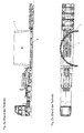
- the Fig. 1a and 1b show in a side view and plan view schematically an example of a prior art semitrailer for transporting a conical, semi-circular precast concrete element L (load), as it is used for the construction of a tower structure of a wind turbine.
- the semitrailer tractor shown comprises a semi-trailer 2 pulled by a semitrailer tractor 1 with a so-called gooseneck 3 (crank) in the front part on which the low-loader 2 is coupled to the tractor 1, an axle assembly 4 consisting of three steered axles in the rear part and one Lademaschine with a Tiefbett-loading area 5 between the gooseneck 3 and the axle assembly 4.
- the precast concrete L is on the low-bed cargo 5 - as in Fig.
- FIG. 1a shows that the low-bed loading area 5 is at a height which is smaller than the diameter of the wheels or tires of the Schuachsan accent 4.
- the precast concrete L claimed almost the entire length of the lowbed loading area. 5
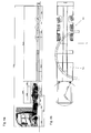
- a larger deep bed loading area is required.
- An example of such a tractor-trailer is in Fig. 2a, 2b shown.
- the larger low-bed loading area 5 'but means a greater overall length and a higher total weight of the trailer.
- a further steered axle may be required.
- the semi-trailer could deviate from the in Fig. 1a, 1b or Fig. 2a, 2b shown embodiment, a telescopic length adjustable (extendable) dock leveler, which allows adjustment of the length of the low-bed cargo area to different large precast concrete parts.
- a telescopic length adjustable (extendable) dock leveler which allows adjustment of the length of the low-bed cargo area to different large precast concrete parts.
- Such telescopic semi-trailers are well known to those skilled in the art and trade magazines. They are manufactured and sold, for example, by the applicant. However, any extension of the semi-trailer truck is subject to limits due to legal requirements as well as stability, weight and cost reasons.
- Raising the cargo bed to a height above the wheels of the rear axle assembly to thereby obtain an increased cargo area while maintaining the same overall length of the flat loader would result in an excessive increase in the overall height of the loaded semi-trailer which is required for road transport of the previously discussed precast concrete products 3800 mm is not practical.
- the present invention seeks to provide a low loader, in particular in the design as a semi-trailer, which provides a sufficiently large cargo area with a relatively simple and lightweight construction, the circular motion segmented, in particular semi-circular, loads, in the Special semicircular prefabricated concrete elements for the construction of a tower structure of a wind turbine allows.
- An inventive low loader for the vertical transport of loads having a circular segment-shaped, in particular semicircular, footprint has a loading surface, which contains an at least in curvature and width of the footprint of a load to be transported corresponding circular ring-shaped bearing surface, and an axle assembly, the at least two in A rigid axle arranged at a predetermined axial spacing, the wheels of which protrude beyond the loading height of the loading surface by wheel recesses spaced apart in the track width direction of the respective rigid axle.
- the annular segment-shaped bearing surface is intended to extend both between the wheels (i.e., the left and right wheels) of the frontward rigid axle in the direction of travel and between the front and rear rigid axles (i.e., the left and right wheels of the front and rear rigid axles).
- a low loader In a low loader according to the invention is a vehicle with a low bed for transporting heavy and / or bulky loads.
- the basic structure, the function and the various embodiments of a low loader are known in the art.
- the low loader according to the invention is designed for the vertical transport of loads with annular segment-shaped, in particular semicircular, footprint.
- the footprint of the load is the ground or underside surface with or on which the respective load is placed on the bed of the low loader, but the footprint does not have to rest on the cargo area.
- loads include in particular conical annular or annular segment-shaped precast concrete elements, such as those used for the construction of a wind turbine tower, with a height of 3600 mm to 3800 mm, a thickness of about 300 mm and, depending on the level at which the respective precast concrete part is installed , an outer radius of 2500 mm to 4850 mm. Due to the large outer diameter, the larger of the prefabricated concrete elements to be transported are designed as circular ring segments, in particular as semicircular rings (also called half shells).
- the bearing surface thus forms part of the loading surface.
- the bearing surface is part of the loading area in the loading area.
- the loading area must therefore cover at least the bearing surface.
- the arc length of the support surface may be smaller than the arc length of the footprint of the load to be transported.
- the load is at one or - as in the Fig. 1b sketched case - both bow ends on the support surface or loading area.
- the bearing surface thus results from the vertically projected onto the loading surface contact surface of the load.
- the loading area may be a continuous flat area or - for example, in the event that the low loader is telescopically - be a possibly composed of partial surfaces flat surface which carries the load to be transported or on which the load to be transported can be parked or arranged.
- a low-loader has in its rear region at least two axle arrangements (having a front and a rear) of the same design, having a predetermined axial spacing.
- the axle arrangement can have one or more further axles, eg rigid axle (s) and / or steered axle (s), in particular a so-called follower steering axle, which in the (forward) direction of travel of the low loader behind the two Rigid axles lies.
- the two rigid axles always form the front axles in (forward) driving direction.
- Such axle arrangements comprising several axles (rigid and / or steered axles) are generally known to the person skilled in the art.
- the spatial extent or space requirement of the two front rigid axles is determined by their tires (single / twin tires and tire size) and their track width.
- the tire size tailored to the weight of the load to be transported determines the size of the wheel recesses receiving the wheels.
- the at least two rigid axles having axle assembly is additionally defined by the axial distance between the two rigid axles. Knowing the tire size, the track width and the track width spacing between the wheels of the rigid axles can be determined by using an appropriate overall width of the flatbed. Alternatively, knowing the overall width of the low loader, the track width and track pitch between the wheels of the rigid axles can be determined by choosing a suitable tire. Analogous considerations apply to the determination of the center distance between the two rigid axles.
- the loading area expands into the region claimed by the two rigid axles, which is limited by the track width of the identical rigid axles, the tires and the center distance between the front and rear rigid axles and therefore calculable or is determinable.
- the circular ring segment-shaped support surface both by lying between the left and right wheels of the front in the direction of travel rigid axle gauge track width range and by lying between the left or right wheels of the front and rear rigid axle center distance range.
- the required track width and the required center distance depending on the dimensions of the load to be transported can be determined by the person skilled in the art such that the annular segment-shaped contact surface of the load (s ) into the limited by the two rigid axles loading area, ie "threading" between the wheels of the two rigid axles.
- the bed located in the area of the two rigid axles comprises a first loading area between the left and right wheels or wheel recesses for the left and right wheels of the front rigid axle and a second loading area between the wheels or wheel recesses for the wheels of the front rigid axle and the wheels or wheel recesses for the wheels of the rear rigid axle.
- the transportable (s) load (s) curvature or outer and inner diameter and thickness
- the inventively provided use of extending in the region of the two rigid axles loading surface as a support surface for the (n) load (s) to be transported over the known over- and Eisenfahrianaladern numerous advantages.
- a significant part of the load is displaced in the direction of the two rigid axles or distributed to the two rigid axles.
- the low loader according to the invention allows a reduction in the total length and thus the weight and the manufacturing or acquisition costs. Deviations from the maximum dimensions provided for in the Highway Code can therefore be kept as low as possible, making special permits easier to reach.
- the centroid of the annular segment-shaped support surface is advantageously at least substantially in the middle of the width of the low loader and the annular ring-shaped bearing surface is advantageous at least substantially symmetrically aligned with respect to a passing through the centroid transverse axis of the low loader.
- the location of the center of gravity of the bearing surface on the bed of the low loader coincides with the position of the projected on the bed volume of gravity of the load.
- the annular-segment-shaped bearing surface is advantageously aligned substantially symmetrically with respect to a passing through the centroid transverse axis of the flatbed trailer, the weight of the load to be transported in the width direction of the trailer is optimally distributed.
- the position of the center of gravity of the arranged in the region of the two rigid axles footprint of the load varies depending on the size of the load to be transported, ie from the outer / inner diameter or outer / inner radius of the load (see Fig. 5b ).
- the lying in (forward) direction of travel of the low loader in front of the two rigid axles or, for example, provided by telescopic extension loading area therefore has a sufficiently large length to order to be arranged before the two rigid axles part of the load can.
- the wheels of the rigid axles can, for example, have twin tires of size 235/75 R 17.55, 245/70 R 17.5, 255/60 R 19.5, 245/70 R 19, 5, 265/70 R 19.5 or 285/70 R 19.5.
- the overall width of the low loader can be extended to an excess width, ie in the range of greater than 2550 mm to a maximum of 3000 mm, advantageously in the range of 2750 mm to 3000 mm, for example at about 2750 mm.
- the width of the cargo bed between the wheels of the rigid axles as measured in the tread width direction may be in the range of 1610 mm to 1650 mm, ideally 1610 mm.
- the length of the loading surface between the wheels of the front rigid axle measured in the axial distance direction is advantageously less than or equal to 900 mm.
- the center distance between the two rigid axles can be greater than or equal to 1360 mm, ideally in the range of 1510 mm to 1650 mm.
- the track widths and center distances specified above take into account not only the space requirements of the wheels or the tires of the rigid axles a required lateral clearance between the wheels and the frame of the trailer and an optionally additionally required distance for attaching fenders or spray protection measures, etc ..
- a low loader according to the invention is advantageously designed as a low-loader semi-trailer with a lower loading surface lying opposite a higher-lying fifth wheel plate and advantageously has a longitudinal telescoping loading bridge.
- a telescopic dock leveler allows flexible adjustment of the length of the loading area to the size of the load to be arranged on the loading area.
- the low loader according to the invention advantageously has, in view of the high weight of the loads to be transported, a steered axle arranged behind the two rigid axles (so-called trailing steering axle).
- An independent invention not claimed in the present application, for which protection may be sought, for example by way of a later patent application claiming the priority of the present application, is a method of carrying a load upright, which an annular segment-shaped, in particular semicircular, footprint has, by means of a low loader according to one of claims 1 to 12.
- the method provides to arrange the load for standing transport on the bed of the low loader so that the footprint of the load between the wheels of in Direction of travel front rigid axle of the trailer and between the left or right wheels of the front and rear rigid axle extends.
- the load can be arranged in particular so that the projected on the bed of the flatbed center of gravity of the footprint of the load in the width center of the trailer.
- the load on the bed of the low loader may be oriented to be symmetrical with respect to a transverse axis of the flatbed passing through the centroid of the footprint of the load projected onto the bed.
- the Fig. 3a and 3b show a first embodiment of a low loader 10 according to the invention in the form of a pulled by a tractor semitrailer.
- the low loader 10 has in a conventional manner, following a higher-lying fifth wheel plate 11, a so-called gooseneck 12 (crank), a low-lying, doppelenzentieleskopierbare loading bridge with a loading area 13 and the rear of the trailer a three axes 15, 16, 17th having axle assembly 14.
- the three axles comprise a front and a rear rigid axle 15, 16 and a steered axle 17 arranged behind the two rigid axles 15, 16 (so-called trailing steering axle).
- the two rigid axles 15, 16 are identical and arranged with an axial distance of about 1650 mm.
- the Fig. 3a and 3b show that each twin-wheeled wheels of each of the three axles 15, 16, 17 each extend through a spaced in the track width direction wheel recess through the loading height of about 560 mm of the cargo area 13 addition.
- the low loader has a total width of 2750 mm.
- the track width of the three axles 15, 16, 17 is about 2190 mm for a tire size 235/75 R 17.55 or 245/70 R 17.5.
- the width of the (first) loading area in the track width direction between the wheels of the front rigid axle 15 is about 1610 mm, and in the axial direction is about 900 mm.
- the loading area 13 is composed of a plurality of partial surfaces, but all at the loading height of 560 mm, ie lie in a plane.
- the loading area 13 according to the invention continues into the areas between the left and right wheels of each of the three axles 15, 16, 17 and over the entire width of the low loader 10 in the Achsabstands Schemee between the three axes 15, 16, 17.
- the low loader 10 according to the invention thus already differs by the extent of the loading area 13 of the well-known over- and Eisenfahrianaladern.
- a standing with the low loader according to the invention in a standing arrangement (see Fig. 1a . 2a ) to be transported load L has a circular segment-shaped, in Fig. 3b semi-circular, footprint L '(bottom or bottom surface) with which the load L is on the bed 13. It should be noted that the footprint 13 does not have to rest on the loading area 13 over the entire area. In the in Fig. 3b sketched example, for example, the footprint L 'of the load L and thus also the load L protrudes at both ends of the bow on the left in (forward) driving direction on the back of the loader 13 of the trailer. In addition, the loading area 13 of several, in Fig. 3b composed of three partial surfaces.
- the loading surface 13 provides a circular-segment-segment-shaped support surface 13 'corresponding at least in curvature and width of the contact surface L' of the load L, which in Fig. 3b indicated by dashed lines.
- the bearing surface 13 ' corresponds to the footprint 13 projected footprint L' of the load.
- the support surface 13 ' is located as a partial surface of the loading area 13 in the loading area 13. It extends through both the track width range between the wheels of the front in the direction of travel rigid axle 15 and by the Achsabstands Scheme between the front and rear rigid axle 15, 16 therethrough Fig. 3b is shown.
- the Fig. 3b indicates that the loading area 13 may be larger than the bearing surface 13 'contained in the loading area 13.
- the footprint of the load L greater than the Support surface 13 '.
- the load L and thus the footprint L 'of the load L projects in the (forward) direction of travel of the flatbed truck 10 on the left side laterally beyond the loading area 13. Due to the laterally projecting footprint L ', the arc length of lying in the bed 13, circular-segment-shaped support surface 13' is smaller than the arc length of the semicircular footprint L '.
- the centroid FSP of the annular segment-shaped support surface 13 'in the width center of the flatbed 10 (on the in Fig. 3b dash-dotted registered longitudinal center axis of the flatbed 10) and is the annular segment-shaped support surface 13 'with respect to a passing through the centroid FSP (in Fig. 3b dash-dotted registered) transverse axis Q of the low loader 10 symmetrically aligned.
- the lateral projection is therefore the same at the two arc ends of the footprint L 'of the load L.
- the position of the center of gravity FSP of the support surface 13 'on the loading surface 13 of the low loader 10 coincides with the position of the projected on the bed 13 (not shown) volume of gravity of the load L.
- the inventively provided use of extending in the region of the two rigid axles 15, 16 loading area 13 as support surface 13 'for the load L to be transported arise over the known over- and Eisenfahrianaladern numerous advantages.
- a not inconsiderable part of the load L is displaced in the direction of the two rigid axles 15, 16 or distributed to the two rigid axles 15, 16.
- the low loader according to the invention allows a reduction in the total length and thus the weight and the manufacturing or acquisition costs. Deviations from the maximum dimensions provided for in the Highway Code can therefore be kept as low as possible, making special permits easier to reach.
- the Fig. 4a, 4b show the low loader 10 Fig. 3a, 3b in a state with a size of the L to be transported correspondingly extended loading area 13.
- Die Fig. 5a, 5b show the low loader 10 out Fig. 3a, 3b In a state with extended loading area 13, which provides space for different sized loads space.
- the telescopic design of the low loader therefore allows a flexible adjustment of the length of the bed 13 and the total length of the low loader 10 to the size of the load to be transported L.
- the Fig. 6a, 6b show a second embodiment of a low loader 100 according to the invention in the form of a pulled by a tractor semitrailer.
- the low loader 100 differs from that with the help of Fig. 3a to 5b presented low loader 10 of the first embodiment only in that it is designed to be simply telescopic lengthened. Apart from that, the low loader is similar to that of the first embodiment.
- the low loader according to the invention although designed for the vertical transport of loads that have a circular ring segment-shaped, in particular semicircular, footprint, but he can of course also use for the transport of annular loads, as in Fig. 6c, 6d is shown.
- the invention relates to a low loader for the vertical transport of a load having a circular segment-shaped, in particular semicircular, footprint, with a loading surface, which contains an at least in curvature and width of the footprint corresponding circular ring-shaped support surface, and an axle assembly, the two arranged at a predetermined center distance Rigid axles comprises, wherein the wheels of each rigid axle protrude through spaced in the track width direction of the respective rigid axle Radaussparieux beyond the loading height of the loading area.
- the invention extends or "meandering" the annular segment-shaped support surface both between the left and right wheels of the front in the direction of travel rigid axle and between the left and right wheels of the front and rear rigid axle.
- the center of gravity of the annular segment-shaped support surface is at least substantially in the middle of the width of the low loader and the annular segment-shaped support surface is aligned at least substantially symmetrically with respect to a passing through the centroid transverse axis of the trailer.
Abstract
Die Erfindung betrifft einen Tieflader (10) zum Stehendtransport einer Last, die eine kreisringsegmentförmige, im Besonderen halbkreisringförmige, Aufstandsfläche hat, mit einer Ladefläche (13), die eine wenigstens in Krümmung und Breite der Aufstandsfläche entsprechende kreisringsegmentförmige Auflagerfläche enthält, und einer Achsanordnung, die zwei in einem vorgegebenen Achsabstand angeordnete Starrachsen (15,16) umfasst, wobei die Räder jeder Starrachse durch in Spurbreitenrichtung der jeweiligen Starrachse beabstandete Radaussparungen hindurch über die Ladehöhe der Ladefläche hinaus ragen. Erfindungsgemäß erstreckt oder "schlängelt" sich die kreisringsegmentförmige Auflagerfläche sowohl zwischen den linken und rechten Rädern der in Fahrtrichtung vorderen Starrachse als auch zwischen den linken und rechten Rädern der vorderen und hinteren Starrachse hindurch. Vorteilhaft liegt der Flächenschwerpunkt der kreisringsegmentförmigen Auflagerfläche (13') zumindest im Wesentlichen in der Breitenmitte des Tiefladers und ist die kreisringsegmentförmige Auflagerfläche bezüglich einer durch den Flächenschwerpunkt gehenden Querachse des Tiefladers zumindest im Wesentlichen symmetrisch ausgerichtet.The invention relates to a low loader (10) for the vertical transport of a load, which has an annular segment-shaped, in particular semicircular, footprint, with a loading surface (13) containing a circular ring segment-shaped bearing surface corresponding at least in curvature and width of the footprint, and an axle assembly, the two arranged in a predetermined center distance rigid axles (15,16), wherein the wheels of each rigid axle protrude through spaced in the track width direction of the respective rigid axle Radaussparungen beyond the loading height of the loading area addition. According to the invention extends or "meandering" the annular segment-shaped support surface both between the left and right wheels of the front in the direction of travel rigid axle and between the left and right wheels of the front and rear rigid axle. Advantageously, the centroid of the annular segment-shaped bearing surface (13 ') is at least substantially in the width center of the trailer and the annular segment-shaped bearing surface is at least substantially symmetrical with respect to a passing through the centroid transverse axis of the low loader.
Description
Die Erfindung betrifft einen Tieflader zum Stehendtransport kreisringsegmentförmiger, im Besonderen halbkreisringförmiger, Lasten, im Besonderen halbkreisringförmiger Betonfertigteile zur Errichtung eines Turmbauwerks einer Windkraftanlage, wie es beispielsweise in der deutschen Patentanmeldung
Die
Die große Anzahl derartiger ring- oder ringsegmentförmiger Betonfertigteile hat in den letzten Jahren dazu geführt, dass für deren Transport relativ schwere und relativ komplex aufgebaute Fahrzeuge konstruiert und gebaut wurden. Die zu transportierenden Betonfertigteile haben üblicherweise eine Höhe von 3600 mm bis 3800 mm, eine Dicke von ca. 300 mm und einen Außenradius von 2500 mm bis zu 4850 mm. Wie es in der
Die
Um im Durchmesser bzw. in der Länge größere Betonfertigteile transportieren zu können, ist eine größere Tiefbett-Ladefläche erforderlich. Ein Beispiel für einen derartigen Sattelzug ist in
Alternativ dazu könnte der Satteltieflader abweichend von der in
Ein Anheben der Ladefläche auf eine Höhe über den Rädern der Hinterachsanordnung, um dadurch bei gleichbleibender Gesamtlänge des Tiefladers eine vergrößerte Ladefläche zu erhalten, würde zu einer übermäßigen Zunahme der Gesamthöhe des beladenen Satteltiefladers resultieren, welche für den Straßentransport der oben diskutierten Betonfertigteile mit einer Höhe von ca. 3800 mm nicht praxistauglich ist.Raising the cargo bed to a height above the wheels of the rear axle assembly to thereby obtain an increased cargo area while maintaining the same overall length of the flat loader would result in an excessive increase in the overall height of the loaded semi-trailer which is required for road transport of the previously discussed precast concrete products 3800 mm is not practical.
Von diesem Hintergrund liegt der Erfindung die Aufgabe zugrunde, einen Tieflader, im Besonderen in der Ausführung als Sattelauflieger, zu schaffen, der mit einer relativ einfachen und leichten Konstruktion eine ausreichend große Ladefläche bereitstellt, die einen Stehendtransport kreisringsegmentförmiger, im Besonderen halbkreisringförmiger, Lasten, im Besonderen halbkreisringförmiger Betonfertigteile zur Errichtung eines Turmbauwerks einer Windkraftanlage, ermöglicht.Against this background, the present invention seeks to provide a low loader, in particular in the design as a semi-trailer, which provides a sufficiently large cargo area with a relatively simple and lightweight construction, the circular motion segmented, in particular semi-circular, loads, in the Special semicircular prefabricated concrete elements for the construction of a tower structure of a wind turbine allows.
Gelöst wird diese Aufgabe durch einen Tieflader mit den Merkmalen des Anspruchs 1. Vorteilhafte Weiterbildungen sind Gegenstand abhängiger Ansprüche.This object is achieved by a low loader with the features of
Ein erfindungsgemäßer Tieflader zum Stehendtransport von Lasten, die eine kreisringsegmentförmige, im Besonderen halbkreisringförmige, Aufstandsfläche haben, weist eine Ladefläche, die eine wenigstens in Krümmung und Breite der Aufstandsfläche einer zu transportierenden Last entsprechende kreisringsegmentförmige Auflagerfläche enthält, und eine Achsanordnung auf, die wenigstens zwei in einem vorgegebenen Achsabstand angeordnete Starrachsen umfasst, deren Räder durch in Spurbreitenrichtung der jeweiligen Starrachse beabstandete Radaussparungen hindurch über die Ladehöhe der Ladefläche hinaus ragen. Erfindungsgemäß soll sich die kreisringsegmentförmige Auflagerfläche sowohl zwischen den Rädern (d.h. den linken und rechten Rädern) der in Fahrtrichtung vorderen Starrachse als auch zwischen der vorderen und hinteren Starrachse (d.h. den linken oder rechten Rädern der vorderen und hinteren Starrachse) hindurch erstrecken.An inventive low loader for the vertical transport of loads having a circular segment-shaped, in particular semicircular, footprint, has a loading surface, which contains an at least in curvature and width of the footprint of a load to be transported corresponding circular ring-shaped bearing surface, and an axle assembly, the at least two in A rigid axle arranged at a predetermined axial spacing, the wheels of which protrude beyond the loading height of the loading surface by wheel recesses spaced apart in the track width direction of the respective rigid axle. According to the invention, the annular segment-shaped bearing surface is intended to extend both between the wheels (i.e., the left and right wheels) of the frontward rigid axle in the direction of travel and between the front and rear rigid axles (i.e., the left and right wheels of the front and rear rigid axles).
Bei einem erfindungsgemäßen Tieflader handelt es sich um ein Fahrzeug mit tief liegender Ladefläche zum Transport schwerer und/oder sperriger Lasten. Der grundsätzliche Aufbau, die Funktion und die verschiedenen Ausführungsformen eines Tiefladers sind dem Fachmann bekannt.In a low loader according to the invention is a vehicle with a low bed for transporting heavy and / or bulky loads. The basic structure, the function and the various embodiments of a low loader are known in the art.
Der erfindungsgemäße Tieflader ist für den Stehendtransport von Lasten mit kreisringsegmentförmiger, im Besonderen halbkreisringförmiger, Aufstandsfläche konzipiert. Bei der Aufstandsfläche der Last handelt es sich um die boden- oder unterseitige Fläche, mit bzw. auf der die jeweilige Last auf der Ladefläche des Tiefladers steht, wobei die Aufstandsfläche jedoch nicht vollflächig auf der Ladefläche aufliegen muss. Derartige Lasten umfassen im Besonderen konische kreisring- oder kreisringsegmentförmige Betonfertigteile, wie sie für die Errichtung eines Windkraftanlagenturms eingesetzt werden, mit einer Höhe von 3600 mm bis 3800 mm, einer Dicke von etwa 300 mm und, je nachdem in welcher Höhe das jeweilige Betonfertigteil verbaut wird, einem Außenradius von 2500 mm bis 4850 mm. Aufgrund des großen Außendurchmessers sind die größeren der zu transportierenden Betonfertigteile als Kreisringsegmente, im Besonderen als Halbkreisringe (auch Halbschalen genannt), ausgeführt.The low loader according to the invention is designed for the vertical transport of loads with annular segment-shaped, in particular semicircular, footprint. The footprint of the load is the ground or underside surface with or on which the respective load is placed on the bed of the low loader, but the footprint does not have to rest on the cargo area. Such loads include in particular conical annular or annular segment-shaped precast concrete elements, such as those used for the construction of a wind turbine tower, with a height of 3600 mm to 3800 mm, a thickness of about 300 mm and, depending on the level at which the respective precast concrete part is installed , an outer radius of 2500 mm to 4850 mm. Due to the large outer diameter, the larger of the prefabricated concrete elements to be transported are designed as circular ring segments, in particular as semicircular rings (also called half shells).
Um derartige Lasten auf der Ladefläche des Tiefladers anordnen zu können, muss die Ladefläche eine wenigstens in Krümmung (bzw. im Außenradius und Innenradius) und Breite (= Dicke der Last) der Aufstandsfläche entsprechende kreisringsegmentförmige Auflagerfläche bereitstellen. Die Auflagerfläche stellt damit einen Teil der Ladefläche dar. Anders ausgedrückt liegt die Auflagerfläche als Teil der Ladefläche in der Ladefläche. Die Ladefläche muss daher wenigstens die Auflagerfläche überdecken. Die Auflagerfläche muss wenigstens in Krümmung (bzw. im Außenradius und Innenradius) und Breite (= Dicke der Last) mit der Aufstandsfläche übereinstimmen. Die Bogenlänge der Auflagerfläche kann dagegen kleiner sein als die Bogenlänge der Aufstandsfläche der zu transportierenden Last. Ist die Bogenlänge der Auflagerfläche kleiner als die Bogenlänge der Aufstandsfläche der zu transportierenden Last, steht die Last an einem oder - wie in dem in
Um die Transporthöhe des mit der Last beladenen Fahrzeugs möglichst gering zu halten, wird eine besonders tiefliegende Ladefläche angestrebt. Die Ladefläche kann eine durchgehende ebene Fläche oder - beispielsweise für den Fall, dass der Tieflader längenteleskopierbar ist - eine gegebenenfalls aus Teilflächen zusammengesetzte ebene Fläche sein, die die zu transportierende Last trägt bzw. auf der die zu transportierende Last abgestellt oder angeordnet werden kann.In order to keep the transport height of the vehicle loaded with the load as low as possible, a particularly low-lying cargo area is sought. The loading area may be a continuous flat area or - for example, in the event that the low loader is telescopically - be a possibly composed of partial surfaces flat surface which carries the load to be transported or on which the load to be transported can be parked or arranged.
Ein erfindungsgemäßer Tieflader weist in seinem Heckbereich eine wenigstens zwei (eine vordere und eine hintere) baugleiche, mit einem vorgegebenen Achsabstand angeordnete Starrachsen aufweisende Achsanordnung auf. Neben den beiden Starrachsen kann die Achsanordnung eine oder mehrere weitere Achsen, z.B. Starrachse(n) und/oder gelenkte Achse(n), im Besonderen eine sog. Nachlauf-Lenkachse, aufweisen, die in (Vorwärts-)Fahrtrichtung des Tiefladers hinter den beiden Starrachsen liegt. Für den Fall, dass mehr als zwei Achsen vorgesehen sind, bilden die beiden Starrachsen stets die in (Vorwärts-)Fahrtrichtung vorderen Achsen. Derartige, mehrere Achsen (Starr- und/oder gelenkter Achsen) umfassende Achsanordnungen sind dem Fachmann grundsätzlich bekannt. Die räumliche Ausdehnung bzw. der Platzbedarf der beiden vorderen Starrachsen ist durch deren Bereifung (Einfach-/Zwillingsbereifung und Reifengröße) sowie deren Spurbreite bestimmt. Die auf das Gewicht der zu transportierenden Last abgestimmte Reifengröße bestimmt die Größe der die Räder aufnehmenden Radaussparungen. Die die wenigstens zwei Starrachsen aufweisende Achsanordnung ist zusätzlich durch den Achsabstand zwischen den beiden Starrachsen definiert. In Kenntnis der Reifengröße können die Spurbreite und der Spurbreitenabstand zwischen den Rädern der Starrachsen durch Verwendung einer passenden Gesamtbreite des Tiefladers bestimmt werden. Alternativ dazu in Kenntnis der Gesamtbreite des Tiefladers können die Spurbreite und der Spurbreitenabstand zwischen den Rädern der Starrachsen durch Wahl einer geeigneten Bereifung bestimmt werden. Analoge Überlegungen gelten für die Bestimmung des Achsabstands zwischen den beiden Starrachsen.A low-loader according to the invention has in its rear region at least two axle arrangements (having a front and a rear) of the same design, having a predetermined axial spacing. In addition to the two rigid axles, the axle arrangement can have one or more further axles, eg rigid axle (s) and / or steered axle (s), in particular a so-called follower steering axle, which in the (forward) direction of travel of the low loader behind the two Rigid axles lies. In the event that more than two axles are provided, the two rigid axles always form the front axles in (forward) driving direction. Such axle arrangements comprising several axles (rigid and / or steered axles) are generally known to the person skilled in the art. The spatial extent or space requirement of the two front rigid axles is determined by their tires (single / twin tires and tire size) and their track width. The tire size tailored to the weight of the load to be transported determines the size of the wheel recesses receiving the wheels. The at least two rigid axles having axle assembly is additionally defined by the axial distance between the two rigid axles. Knowing the tire size, the track width and the track width spacing between the wheels of the rigid axles can be determined by using an appropriate overall width of the flatbed. Alternatively, knowing the overall width of the low loader, the track width and track pitch between the wheels of the rigid axles can be determined by choosing a suitable tire. Analogous considerations apply to the determination of the center distance between the two rigid axles.
Im Unterschied zu einem sog. Überfahrtieflader, bei dem alle Räder der Achsanordnung unter der Ladefläche liegen, ragen bei dem erfindungsgemäßen Tieflader die Räder der Achsanordnung durch in Spurbreitenrichtung der jeweiligen Starrachse beabstandete Radaussparungen hindurch über die Ladehöhe der Ladefläche hinaus. Der Raddurchmesser der Räder ist also größer als die von der Fahrbahn aus gemessene Ladehöhe der Ladefläche des Tiefladers. Im Unterschied zu einem sog. Zwischenfahrtieflader, bei dem sich die Ladefläche lediglich durch den zwischen den linken und rechten Rädern liegenden Bereich hindurch erstreckt, dehnt sich bei dem erfindungsgemäßen Tieflader die Ladefläche auch in den Achsabstandsbereich zwischen der vorderen und hinteren Starrachse über die Gesamtbreite des Tiefladers aus. Bei dem erfindungsgemäßen Tieflader dehnt sich die Ladefläche daher in den von der Hinterachsanordnung, im Besonderen den von den beiden Starrachse beanspruchten Bereich aus, der durch die Spurbreite der baugleichen Starrachsen, die Bereifung und den Achsabstand zwischen der vorderen und hinteren Starrachse begrenzt und daher berechenbar oder bestimmbar ist.In contrast to a so-called. Überfahrtieflader, in which all wheels of the axle assembly lie under the bed, protrude in the low loader according to the invention, the wheels of the axle assembly in spaced in the track width direction of the respective rigid axle Radaussparungen beyond the loading height of the loading area. The wheel diameter of the wheels is thus greater than the measured from the road surface loading height of the bed of the low loader. In contrast to a so-called. Zwischenfahrtieflader, in which the loading surface extends through only lying between the left and right wheels area extends in the low loader according to the invention, the cargo area in the Achsabstandsbereich between the front and rear rigid axle over the entire width of the trailer out. In the low loader according to the invention, therefore, the loading area expands into the region claimed by the two rigid axles, which is limited by the track width of the identical rigid axles, the tires and the center distance between the front and rear rigid axles and therefore calculable or is determinable.
Erfindungsgemäß erstreckt oder "schlängelt" sich die kreisringsegmentförmige Auflagerfläche sowohl durch den zwischen den linken und rechten Rädern der in Fahrtrichtung vorderen Starrachse liegenden Spurbreitenabstandsbereich als auch durch den zwischen den linken oder rechten Rädern der vorderen und hinteren Starrachse liegenden Achsabstandsbereich hindurch. In Kenntnis der Bereifung und der Gesamtbreite des Tiefladers lassen sich für den Fachmann die erforderliche Spurbreite und der erforderliche Achsabstand in Abhängigkeit von den Ausmaßen der zu transportierenden Last(en) rechnerisch und/oder zeichnerisch so ermitteln, dass sich die kreisringsegmentförmige Aufstandsfläche der Last(en) bis in den durch die beiden Starrachsen begrenzten Ladeflächenbereich hineinlegen, d.h. zwischen die Räder der beiden Starrachsen hindurch "einfädeln", lässt.According to the invention extends or "meanders" the circular ring segment-shaped support surface both by lying between the left and right wheels of the front in the direction of travel rigid axle gauge track width range and by lying between the left or right wheels of the front and rear rigid axle center distance range. With knowledge of the tires and the overall width of the low loader, the required track width and the required center distance depending on the dimensions of the load to be transported (computationally and / or graphically) can be determined by the person skilled in the art such that the annular segment-shaped contact surface of the load (s ) into the limited by the two rigid axles loading area, ie "threading" between the wheels of the two rigid axles.
Die im Bereich der beiden Starrachsen liegende Ladefläche umfasst einen ersten Ladeflächenbereich zwischen den linken und rechten Rädern oder Radaussparungen für die linken und rechten Räder der vorderen Starrachse und einen zweiten Ladeflächenbereich zwischen den Rädern oder Radaussparungen für die Räder der vorderen Starrachse und den Rädern oder Radaussparungen für die Räder der hinteren Starrachse. Erfindungsgemäß sind die in Spurbreitenrichtung der vorderen Starrachse gemessene Breite des ersten Ladeflächenbereichs (oder der Abstand der in Spurbreitenrichtung gegenüberliegenden Radaussparungen für die Räder der vorderen Starrachse) und die in Achsabstandsrichtung der beiden Starrachsen gemessene Länge des zweiten Ladeflächenbereichs (oder der Abstand der in Achsabstandsrichtung hintereinanderliegenden Radaussparungen für die Räder der vorderen Starrachse und hinteren Starrachse) im Besonderen also so auf die zu transportierende(n) Last(en) (Krümmung bzw. Außen- und Innendurchmesser und Dicke) abgestimmt, dass sich bei einer stehenden Anordnung auf der Ladefläche des Tiefladers die Aufstandsfläche jeder Last bzw. die ladeflächenseitige Auflagerfläche durch den ersten Ladeflächenbereich und zweiten Ladeflächenbereich hindurch erstreckt.The bed located in the area of the two rigid axles comprises a first loading area between the left and right wheels or wheel recesses for the left and right wheels of the front rigid axle and a second loading area between the wheels or wheel recesses for the wheels of the front rigid axle and the wheels or wheel recesses for the wheels of the rear rigid axle. According to the invention measured in the track width direction of the front rigid axle width of the first loading area (or the distance of the opposite in the track width direction Radaussparungen for the wheels of the front rigid axle) and in the axial spacing of the two rigid axles measured length of the second loading area (or the distance of the successive Radaussparungen in Achsabstandsrichtung for the wheels of the front rigid axle and rear rigid axle) in particular so on the transportable (s) load (s) (curvature or outer and inner diameter and thickness) matched that in a standing support arrangement on the bed of the low loader, the footprint of each load or the loading surface side bearing surface extends through the first loading area and the second loading area.
Durch die erfindungsgemäß vorgesehene Nutzung der sich in den Bereich der beiden Starrachsen erstreckenden Ladefläche als Auflagerfläche für die zu transportierende(n) Last(en) ergeben sich gegenüber den bekannten Über- und Zwischenfahrtiefladern zahlreiche Vorteile. Zunächst wird ein nicht unerheblicher Teil der Last in Richtung der beiden Starrachsen verlagert bzw. auf die beiden Starrachsen verteilt. Verglichen mit einem herkömmlichen Tieflader, bei dem die gesamte Last auf der Ladefläche vor der Achsanordnung ruht, ermöglicht der erfindungsgemäße Tieflader eine Verkürzung der Gesamtlänge und damit des Gewichts und der Herstell- bzw. Anschaffungskosten. Abweichungen von den in der Straßenverkehrsordnung vorgesehenen Maximalabmessungen lassen sich daher so gering als möglich halten, wodurch Sondergenehmigungen leichter erreichbar sind.The inventively provided use of extending in the region of the two rigid axles loading surface as a support surface for the (n) load (s) to be transported over the known over- and Zwischenfahrtiefladern numerous advantages. First, a significant part of the load is displaced in the direction of the two rigid axles or distributed to the two rigid axles. Compared with a conventional low loader, in which the entire load rests on the bed in front of the axle assembly, the low loader according to the invention allows a reduction in the total length and thus the weight and the manufacturing or acquisition costs. Deviations from the maximum dimensions provided for in the Highway Code can therefore be kept as low as possible, making special permits easier to reach.
Erfindungsgemäß liegt der Flächenschwerpunkt der kreisringsegmentförmigen Auflagerfläche vorteilhaft zumindest im Wesentlichen in der Breitenmitte des Tiefladers und ist die kreisringsegmentförmige Auflagerfläche vorteilhaft bezüglich einer durch den Flächenschwerpunkt gehenden Querachse des Tiefladers zumindest im Wesentlichen symmetrisch ausgerichtet. Die Lage des Flächenschwerpunkts der Auflagerfläche auf der Ladefläche des Tiefladers stimmt mit der Lage des auf die Ladefläche projizierten Volumenschwerpunkts der Last überein. Wenn die kreisringsegmentförmige Auflagerfläche so angeordnet ist, dass deren Flächenschwerpunkt im Wesentlichen in der Breitenmitte der Ladefläche des Tiefladers, d.h. auf einer Längsmittelachse des Tiefladers, liegt und die kreisringsegmentförmige Auflagerfläche vorteilhaft bezüglich einer durch den Flächenschwerpunkt gehenden Querachse des Tiefladers im Wesentlichen symmetrisch ausgerichtet ist, ist das Gewicht der zu transportierenden Last in Breitenrichtung des Tiefladers optimal verteilt.According to the invention, the centroid of the annular segment-shaped support surface is advantageously at least substantially in the middle of the width of the low loader and the annular ring-shaped bearing surface is advantageous at least substantially symmetrically aligned with respect to a passing through the centroid transverse axis of the low loader. The location of the center of gravity of the bearing surface on the bed of the low loader coincides with the position of the projected on the bed volume of gravity of the load. When the annular segment-shaped bearing surface is arranged so that its centroid is substantially in the middle of the width of the bed of the flatbed, i. on a longitudinal central axis of the low loader, and the annular-segment-shaped bearing surface is advantageously aligned substantially symmetrically with respect to a passing through the centroid transverse axis of the flatbed trailer, the weight of the load to be transported in the width direction of the trailer is optimally distributed.
In Längsrichtung des Tiefladers variiert die Lage des Flächenschwerpunkts der im Bereich der beiden Starrachsen angeordneten Aufstandsfläche der Last in Abhängigkeit von der Größe der zu transportierenden Last, d.h. vom Außen-/Innendurchmesser bzw. Außen-/Innenradius der Last (vgl. hierzu z.B.
Da die zu transportierenden Lasten oftmals überbreit sind, ist eine relativ große Spurbreite erwünscht, um eine vernünftige Auflagerfläche gewährleisten zu können. Im Vergleich zu herkömmlichen Tiefladern gelingt dies durch die Vergrößerung der Spurbreiten der beiden Starrachsen auf mindestens 2040 mm, idealerweise von 2140 mm bis 2230 mm. Die Spurbreite wird bestimmt durch die Bereifung und Reifengröße jeder Starrachse und die Gesamtbreite des Tiefladers. Im Hinblick auf das hohe Gewicht der zu transportierenden Lasten können die Räder der Starrachsen beispielsweise eine Zwillingsbereifung der Größe 235/75 R 17,5, 245/70 R 17,5, 255/60 R 19,5, 245/70 R 19,5, 265/70 R 19,5 oder 285/70 R 19,5 aufweisen. Im Hinblick auf eine vernünftige Auflagerfläche kann die Gesamtbreite des Tiefladers auf eine Überbreite ausgedehnt werden, d.h. im Bereich größer als 2550 mm bis maximal 3000 mm, vorteilhaft im Bereich von 2750 mm bis 3000 mm, z.B. in etwa bei 2750 mm, liegen.Since the loads to be transported are often over-wide, a relatively large track width is desired in order to ensure a reasonable support surface can. Compared to conventional Low loaders achieve this by increasing the track widths of the two rigid axles to at least 2040 mm, ideally from 2140 mm to 2230 mm. The track width is determined by the tires and tire size of each live axle and the total width of the trailer. In view of the high weight of the loads to be transported, the wheels of the rigid axles can, for example, have twin tires of size 235/75 R 17.55, 245/70 R 17.5, 255/60 R 19.5, 245/70
Je nach Bereifung, Reifengröße und Gesamtbreite kann die in Spurbreitenrichtung gemessene Breite der Ladefläche zwischen den Rädern der Starrachsen im Bereich von 1610 mm bis 1650 mm, idealerweise bei 1610 mm, liegen. Des Weiteren ist die in Achsabstandsrichtung gemessene Länge der Ladefläche zwischen den Rädern der vorderen Starrachse vorteilhaft kleiner-gleich 900 mm.Depending on tires, tire size and overall width, the width of the cargo bed between the wheels of the rigid axles as measured in the tread width direction may be in the range of 1610 mm to 1650 mm, ideally 1610 mm. Furthermore, the length of the loading surface between the wheels of the front rigid axle measured in the axial distance direction is advantageously less than or equal to 900 mm.
Je nach Reifengröße kann der Achsabstand zwischen den beiden Starrachsen größer-gleich 1360 mm sein, idealerweise im Bereich von 1510 mm bis 1650 mm liegen.Depending on the tire size, the center distance between the two rigid axles can be greater than or equal to 1360 mm, ideally in the range of 1510 mm to 1650 mm.
Die oben angegebenen Spurbreiten und Achsabstände berücksichtigen neben dem Platzbedarf der Räder bzw. der Bereifung der Starrachsen ein erforderliches seitliches Spiel zwischen den Rädern und dem Rahmen des Tiefladers sowie einen gegebenenfalls zusätzlich erforderlichen Abstand zur Anbringung von Kotflügeln bzw. Spritzschutzmaßnahmen, etc..The track widths and center distances specified above take into account not only the space requirements of the wheels or the tires of the rigid axles a required lateral clearance between the wheels and the frame of the trailer and an optionally additionally required distance for attaching fenders or spray protection measures, etc ..
Ein erfindungsgemäßer Tieflader ist vorteilhaft als ein Satteltieflader mit einer gegenüber einer höher liegenden Sattelplatte tiefer liegende Ladefläche ausgeführt und hat vorteilhaft eine längenteleskopierbare Ladebrücke. Eine längenteleskopierbare Ladebrücke ermöglicht eine flexible Anpassung der Länge der Ladefläche an die Größe der auf der Ladefläche anzuordnenden Last.A low loader according to the invention is advantageously designed as a low-loader semi-trailer with a lower loading surface lying opposite a higher-lying fifth wheel plate and advantageously has a longitudinal telescoping loading bridge. A telescopic dock leveler allows flexible adjustment of the length of the loading area to the size of the load to be arranged on the loading area.
Des Weiteren hat der erfindungsgemäße Tieflader im Hinblick auf das hohe Gewicht der zu transportierenden Lasten vorteilhaft eine hinter den beiden Starrachsen angeordnete gelenkte Achse (sog. Nachlauf-Lenkachse).Furthermore, the low loader according to the invention advantageously has, in view of the high weight of the loads to be transported, a steered axle arranged behind the two rigid axles (so-called trailing steering axle).
Eine in der vorliegenden Anmeldung nicht beanspruchte, unabhängige Erfindung, für die z.B. im Wege einer späteren Patentnachanmeldung, die die Priorität der vorliegenden Anmeldung in Anspruch nimmt, um Schutz nachgesucht werden kann, ist ein Verfahren zum Stehendtransport einer Last, die eine kreisringsegmentförmige, im Besonderen halbkreisringförmige, Aufstandsfläche hat, mit Hilfe eines Tiefladers nach einem der Ansprüche 1 bis 12. Das Verfahren sieht vor, die Last zum Stehendtransport auf der Ladefläche des Tiefladers so anzuordnen, dass sich die Aufstandsfläche der Last zwischen den Rädern der in Fahrtrichtung vorderen Starrachse des Tiefladers als auch zwischen die linken oder rechten Räder der vorderen und hinteren Starrachse hindurch erstreckt. Dabei kann die Last im Besonderen so angeordnet werden, dass der auf die Ladefläche des Tiefladers projizierte Flächenschwerpunkt der Aufstandsfläche der Last in der Breitenmitte des Tiefladers liegt. Des Weiteren kann die Last auf der Ladefläche des Tiefladers so ausgerichtet werden, dass sie bezüglich einer Querachse des Tiefladers, die durch den auf die Ladefläche projizierten Flächenschwerpunkt der Aufstandsfläche der Last geht, symmetrisch ist.An independent invention not claimed in the present application, for which protection may be sought, for example by way of a later patent application claiming the priority of the present application, is a method of carrying a load upright, which an annular segment-shaped, in particular semicircular, footprint has, by means of a low loader according to one of
Anhand der beigefügten Zeichnungen werden im Folgenden beispielhafte Ausführungsformen eines erfindungsgemäßen Tiefladers erläutert. In den Zeichnungen zeigt:
-
Fig. 1a eine Seitenansicht eines Beispiels für einen Sattelzug nach dem Stand der Technik mit einem von einer Sattelzugmaschine gezogenen Satteltieflader zum Stehendtransport eines halbringförmigen Betonfertigteils; -
Fig. 1b eine Draufsicht des Sattelzugs ausFig. 1a ; -
Fig. 2a eine Seitenansicht eines weiteren Beispiels für einen Sattelzug nach dem Stand der Technik mit einem von einer Sattelzugmaschine gezogenen Satteltieflader zum Stehendtransport eines halbringförmigen Betonfertigteils; -
Fig. 2b eine Draufsicht des Sattelzugs ausFig. 2a ; -
Fig. 3a eine Seitenansicht eines Sattelzugs mit einem von einer Sattelzugmaschine gezogenen, teleskopierbaren Satteltieflader gemäß einer ersten Ausführungsform der Erfindung; -
Fig. 3b eine Draufsicht des Satteltiefladers ausFig. 3a ; -
Fig. 4a eine Seitenansicht des Sattelzugs ausFig. 3a mit einer vergrößerten Ladefläche; -
Fig. 4b eine Draufsicht des Satteltiefladers ausFig. 3a ; -
Fig. 5a eine derFig. 3a entsprechende Seitenansicht; -
Fig. 5b eine derFig. 3b entsprechende Draufsicht zur Erläuterung der Längsrichtungslagen verschieden großer halbkreisringförmiger Lasten auf der Ladefläche; -
Fig. 6a eine Seitenansicht eines Sattelzugs mit einem von einer Sattelzugmaschine gezogenen, teleskopierbaren Satteltieflader gemäß einer zweiten Ausführungsform der Erfindung; und -
Fig. 6b eine Draufsicht des Satteltiefladers ausFig. 6a ; -
Fig. 6c eine Seitenansicht des Sattelzugs ausFig. 6a mit einer kreisringförmigen Last auf der Ladefläche; und -
Fig. 6d eine Draufsicht des Satteltiefladers ausFig. 6c .
-
Fig. 1a a side view of an example of a semitrailer tractor according to the prior art with a pulled by a tractor semitrailer for standing transport of a semi-annular precast concrete part; -
Fig. 1b a top view of the tractorFig. 1a ; -
Fig. 2a a side view of another example of a tractor-trailer according to the prior art with a pulled by a tractor semitrailer for standing transport of a semi-annular precast concrete part; -
Fig. 2b a top view of the tractorFig. 2a ; -
Fig. 3a a side view of a tractor-trailer with a pulled by a tractor, telescopic semi-trailer low loader according to a first embodiment of the invention; -
Fig. 3b a top view of the semi-trailerFig. 3a ; -
Fig. 4a a side view of the tractorFig. 3a with an enlarged loading area; -
Fig. 4b a top view of the semi-trailerFig. 3a ; -
Fig. 5a one of theFig. 3a corresponding side view; -
Fig. 5b one of theFig. 3b corresponding plan view for explaining the longitudinal direction layers of different sized semicircular loads on the bed; -
Fig. 6a a side view of a tractor-trailer with a drawn by a tractor, telescopic semi-trailer low loader according to a second embodiment of the invention; and -
Fig. 6b a top view of the semi-trailerFig. 6a ; -
Fig. 6c a side view of the tractorFig. 6a with an annular load on the bed; and -
Fig. 6d a top view of the semi-trailerFig. 6c ,
Die
Die drei Achsen umfassen eine vordere und einen hintere Starrachse 15, 16 sowie eine hinter den beiden Starrachsen 15, 16 angeordnete gelenkte Achse 17 (sog. Nachlauf-Lenkachse). Die beiden Starrachsen 15, 16 sind baugleich und mit einem Achsabstand von etwa 1650 mm angeordnet. Die
In der gezeigten Ausführungsform hat der Tieflader eine Gesamtbreite von 2750 mm. Die Spurbreite der drei Achsen 15, 16, 17 beträgt etwa 2190 mm bei einer Reifengröße 235/75 R 17,5 oder 245/70 R 17,5. Bei dieser Konfiguration ergibt sich für den zwischen den Rädern der vorderen Starrachse 15 liegenden (ersten) Ladeflächenbereich in Spurbreitenrichtung eine Breite von etwa 1610 mm und in Achsabstandrichtung eine Länge von etwa 900 mm.In the embodiment shown, the low loader has a total width of 2750 mm. The track width of the three
Die.
Erfindungsgemäß sind bei dem in
Eine mit dem erfindungsgemäßen Tieflader in stehender Anordnung (vgl. hierzu
Die Ladefläche 13 sieht erfindungsgemäß eine wenigstens in Krümmung und Breite der Aufstandsfläche L' der Last L entsprechende kreisringsegmentförmige Auflagerfläche 13' vor, die in
Erfindungsgemäß liegt der Flächenschwerpunkt FSP der kreisringsegmentförmigen Auflagerfläche 13' in der Breitenmitte des Tiefladers 10 (auf der in
Durch die erfindungsgemäß vorgesehene Nutzung der sich in den Bereich der beiden Starrachsen 15, 16 erstreckenden Ladefläche 13 als Auflagerfläche 13' für die zu transportierende Last L ergeben sich gegenüber den bekannten Über- und Zwischenfahrtiefladern zahlreiche Vorteile. Zunächst wird ein nicht unerheblicher Teil der Last L in Richtung der beiden Starrachsen 15, 16 verlagert bzw. auf die beiden Starrachsen 15, 16 verteilt. Verglichen mit einem herkömmlichen Tieflader, bei dem die gesamte Last auf der Ladefläche vor der Achsanordnung ruht, ermöglicht der erfindungsgemäße Tieflader eine Verkürzung der Gesamtlänge und damit des Gewichts und der Herstell- bzw. Anschaffungskosten. Abweichungen von den in der Straßenverkehrsordnung vorgesehenen Maximalabmessungen lassen sich daher so gering als möglich halten, wodurch Sondergenehmigungen leichter erreichbar sind.The inventively provided use of extending in the region of the two
Durch die Anordnung der kreisringsegmentförmigen Auflagerfläche 13' so, dass deren Flächenschwerpunkt FSP im Wesentlichen in der Breitenmitte der Ladefläche 13 des Tiefladers 10 liegt und die kreisringsegmentförmige Auflagerfläche 13' bezüglich einer durch den Flächenschwerpunkt FSP gehenden Querachse Q des Tiefladers 10 im Wesentlichen symmetrisch ausgerichtet ist, ist das Gewicht der zu transportierenden Last in Breitenrichtung des Tiefladers optimal auf die linken und rechten Räder der Achsanordnung 14 verteilt.Due to the arrangement of the annular segment-shaped support surface 13 'so that their centroid FSP is located substantially in the middle of the width of the
Die
Die
Lediglich der guten Ordnung halber sei darauf hingewiesen, dass der erfindungsgemäßen Tieflader zwar für den Stehendtransport von Lasten, die eine kreisringsegmentförmige, im Besonderen halbkreisringförmige, Aufstandsfläche haben, konzipiert ist, er sich aber natürlich auch für den Transport kreisringförmiger Lasten nutzen lässt, wie es in
Die Erfindung betrifft einen Tieflader zum Stehendtransport einer Last, die eine kreisringsegmentförmige, im Besonderen halbkreisringförmige, Aufstandsfläche hat, mit einer Ladefläche, die eine wenigstens in Krümmung und Breite der Aufstandsfläche entsprechende kreisringsegmentförmige Auflagerfläche enthält, und einer Achsanordnung, die zwei in einem vorgegebenen Achsabstand angeordnete Starrachsen umfasst, wobei die Räder jeder Starrachse durch in Spurbreitenrichtung der jeweiligen Starrachse beabstandete Radaussparungen hindurch über die Ladehöhe der Ladefläche hinaus ragen. Erfindungsgemäß erstreckt oder "schlängelt" sich die kreisringsegmentförmige Auflagerfläche sowohl zwischen den linken und rechten Rädern der in Fahrtrichtung vorderen Starrachse als auch zwischen den linken und rechten Rädern der vorderen und hinteren Starrachse hindurch. Vorteilhaft liegt der Flächenschwerpunkt der kreisringsegmentförmigen Auflagerfläche zumindest im Wesentlichen in der Breitenmitte des Tiefladers und ist die kreisringsegmentförmige Auflagerfläche bezüglich einer durch den Flächenschwerpunkt gehenden Querachse des Tiefladers zumindest im Wesentlichen symmetrisch ausgerichtet.The invention relates to a low loader for the vertical transport of a load having a circular segment-shaped, in particular semicircular, footprint, with a loading surface, which contains an at least in curvature and width of the footprint corresponding circular ring-shaped support surface, and an axle assembly, the two arranged at a predetermined center distance Rigid axles comprises, wherein the wheels of each rigid axle protrude through spaced in the track width direction of the respective rigid axle Radaussparungen beyond the loading height of the loading area. According to the invention extends or "meandering" the annular segment-shaped support surface both between the left and right wheels of the front in the direction of travel rigid axle and between the left and right wheels of the front and rear rigid axle. Advantageously, the center of gravity of the annular segment-shaped support surface is at least substantially in the middle of the width of the low loader and the annular segment-shaped support surface is aligned at least substantially symmetrically with respect to a passing through the centroid transverse axis of the trailer.
Claims (12)
die kreisringsegmentförmige Auflagerfläche (13') sich sowohl zwischen den Rädern der in Fahrtrichtung vorderen Starrachse (15) als auch zwischen der vorderen und hinteren Starrachse (15, 16) hindurch erstreckt.Low loader (10) for the vertical transport of a load (L) having a circular segment-shaped, in particular semicircular, footprint (L '), with a loading surface (13), the at least in curvature and width of the footprint (L') corresponding circular ring-shaped support surface (13 '), and an axle assembly (14) which comprises two rigid axles (15, 16) arranged at a predetermined center distance, the wheels of each rigid axle (15, 16) being spaced apart in the track widthwise direction over the loading height of the loading surface (15, 16). 13) protrude, characterized in that
the annular segment-shaped support surface (13 ') extending both between the wheels of the front in the direction of travel rigid axle (15) and between the front and rear rigid axle (15, 16) therethrough.
Applications Claiming Priority (1)
| Application Number | Priority Date | Filing Date | Title |
|---|---|---|---|
| DE202015102555.6U DE202015102555U1 (en) | 2015-05-19 | 2015-05-19 | TIEFLADER FOR TRANSPORTING CIRCLE RING SEGMENTALLY LOADS |
Publications (1)
| Publication Number | Publication Date |
|---|---|
| EP3098142A1 true EP3098142A1 (en) | 2016-11-30 |
Family
ID=53801676
Family Applications (1)
| Application Number | Title | Priority Date | Filing Date |
|---|---|---|---|
| EP16168692.8A Withdrawn EP3098142A1 (en) | 2015-05-19 | 2016-05-09 | Low-loader for transporting circular ring segment shaped loads |
Country Status (2)
| Country | Link |
|---|---|
| EP (1) | EP3098142A1 (en) |
| DE (1) | DE202015102555U1 (en) |
Cited By (1)
| Publication number | Priority date | Publication date | Assignee | Title |
|---|---|---|---|---|
| WO2022127096A1 (en) * | 2020-12-15 | 2022-06-23 | 中铁上海工程局集团有限公司 | Fixing device for slabs, and transport device |
Citations (5)
| Publication number | Priority date | Publication date | Assignee | Title |
|---|---|---|---|---|
| US2955837A (en) * | 1959-10-23 | 1960-10-11 | William W Bachtell | Trailer construction |
| US4119224A (en) * | 1976-02-12 | 1978-10-10 | David Moody | Vehicle of adjustable width |
| US5924754A (en) * | 1997-05-30 | 1999-07-20 | E-Z Trail, Inc. | Adjustable dimension trailer |
| DE19924889A1 (en) * | 1998-06-03 | 2000-03-23 | Goldhofer Fahrzeugwerk | Road transporter for carrying large, heavy, cumbersome round or rectangular components has frame with lower and upper telescopic sections swivelling in transverse direction around relatively adjustable co-axial pivot points |
| DE102011076648A1 (en) | 2011-05-27 | 2012-11-29 | Max Bögl Wind AG | Method for erecting a wind turbine |
-
2015
- 2015-05-19 DE DE202015102555.6U patent/DE202015102555U1/en not_active Expired - Lifetime
-
2016
- 2016-05-09 EP EP16168692.8A patent/EP3098142A1/en not_active Withdrawn
Patent Citations (5)
| Publication number | Priority date | Publication date | Assignee | Title |
|---|---|---|---|---|
| US2955837A (en) * | 1959-10-23 | 1960-10-11 | William W Bachtell | Trailer construction |
| US4119224A (en) * | 1976-02-12 | 1978-10-10 | David Moody | Vehicle of adjustable width |
| US5924754A (en) * | 1997-05-30 | 1999-07-20 | E-Z Trail, Inc. | Adjustable dimension trailer |
| DE19924889A1 (en) * | 1998-06-03 | 2000-03-23 | Goldhofer Fahrzeugwerk | Road transporter for carrying large, heavy, cumbersome round or rectangular components has frame with lower and upper telescopic sections swivelling in transverse direction around relatively adjustable co-axial pivot points |
| DE102011076648A1 (en) | 2011-05-27 | 2012-11-29 | Max Bögl Wind AG | Method for erecting a wind turbine |
Cited By (1)
| Publication number | Priority date | Publication date | Assignee | Title |
|---|---|---|---|---|
| WO2022127096A1 (en) * | 2020-12-15 | 2022-06-23 | 中铁上海工程局集团有限公司 | Fixing device for slabs, and transport device |
Also Published As
| Publication number | Publication date |
|---|---|
| DE202015102555U1 (en) | 2015-07-23 |
Similar Documents
| Publication | Publication Date | Title |
|---|---|---|
| EP3653435B1 (en) | Vehicle for transporting a long transported item | |
| DE212013000022U1 (en) | Arrangement in a forestry machine and equipped with a corresponding arrangement forest machine | |
| DE202012010545U1 (en) | Heavy-duty transport vehicle for transporting an elongate object | |
| EP2917070A2 (en) | Heavy-load transport vehicle for transporting an elongated object | |
| DE60104955T2 (en) | Reconfigurable crane carrier | |
| DE102012021613A1 (en) | Heavy load-transport vehicle for transporting elongated object i.e. rotor blade, of wind-power plant, has towing machine and support rotated with respect to each other around vertical axis of vehicle | |
| EP3326892A1 (en) | Transport trailer with running gear and at least one floor platform | |
| DE202008009572U1 (en) | car trailers | |
| EP3098142A1 (en) | Low-loader for transporting circular ring segment shaped loads | |
| EP0214163B1 (en) | Chassis of a heavy vehicle, particularly a multiaxle moving crane | |
| EP1122151B1 (en) | Vehicle with low-level extensible loading platform | |
| EP3150428B1 (en) | Transport vehicle for motor vehicles with variable transport surface and method for loading such a transport vehicle | |
| CH673988A5 (en) | ||
| WO1987005888A1 (en) | Wheel or crawler truck | |
| DE102014008720B4 (en) | Heavy truck with forklift function | |
| EP3156310A1 (en) | Drive-less agricultural auxiliary vehicle | |
| DE102016111308A1 (en) | Chassis assembly and land vehicle | |
| DE102007049673A1 (en) | Damaged aircraft recovering method for use during e.g. forced landing, involves lifting construction in such manner that one of supporting elements is insertable into construction, and carrying load received by pieces over elements | |
| EP1366971B1 (en) | Trailer tractor | |
| EP3412620B1 (en) | Construction crane and construction crane system | |
| EP3461785B1 (en) | Crane | |
| DE202016101503U1 (en) | Construction crane and body crane system | |
| DE102020118775A1 (en) | Mobile crane with support device | |
| DE202016100825U1 (en) | chassis | |
| EP3393963B1 (en) | Modular crane, transport unit for a modular crane and method for operating a crane of this type |
Legal Events
| Date | Code | Title | Description |
|---|---|---|---|
| PUAI | Public reference made under article 153(3) epc to a published international application that has entered the european phase |
Free format text: ORIGINAL CODE: 0009012 |
|
| 17P | Request for examination filed |
Effective date: 20160509 |
|
| AK | Designated contracting states |
Kind code of ref document: A1 Designated state(s): AL AT BE BG CH CY CZ DE DK EE ES FI FR GB GR HR HU IE IS IT LI LT LU LV MC MK MT NL NO PL PT RO RS SE SI SK SM TR |
|
| AX | Request for extension of the european patent |
Extension state: BA ME |
|
| 17Q | First examination report despatched |
Effective date: 20190107 |
|
| GRAP | Despatch of communication of intention to grant a patent |
Free format text: ORIGINAL CODE: EPIDOSNIGR1 |
|
| INTG | Intention to grant announced |
Effective date: 20190913 |
|
| STAA | Information on the status of an ep patent application or granted ep patent |
Free format text: STATUS: THE APPLICATION IS DEEMED TO BE WITHDRAWN |
|
| 18D | Application deemed to be withdrawn |
Effective date: 20200124 |