EP3098142A1 - Camionnette surbaissee pour le transport de charges en forme de segment de couronne - Google Patents
Camionnette surbaissee pour le transport de charges en forme de segment de couronne Download PDFInfo
- Publication number
- EP3098142A1 EP3098142A1 EP16168692.8A EP16168692A EP3098142A1 EP 3098142 A1 EP3098142 A1 EP 3098142A1 EP 16168692 A EP16168692 A EP 16168692A EP 3098142 A1 EP3098142 A1 EP 3098142A1
- Authority
- EP
- European Patent Office
- Prior art keywords
- loader
- low
- rigid
- low loader
- axle
- Prior art date
- Legal status (The legal status is an assumption and is not a legal conclusion. Google has not performed a legal analysis and makes no representation as to the accuracy of the status listed.)
- Withdrawn
Links
Images


Classifications
-
- B—PERFORMING OPERATIONS; TRANSPORTING
- B60—VEHICLES IN GENERAL
- B60P—VEHICLES ADAPTED FOR LOAD TRANSPORTATION OR TO TRANSPORT, TO CARRY, OR TO COMPRISE SPECIAL LOADS OR OBJECTS
- B60P3/00—Vehicles adapted to transport, to carry or to comprise special loads or objects
- B60P3/40—Vehicles adapted to transport, to carry or to comprise special loads or objects for carrying long loads, e.g. with separate wheeled load supporting elements
-
- B—PERFORMING OPERATIONS; TRANSPORTING
- B60—VEHICLES IN GENERAL
- B60P—VEHICLES ADAPTED FOR LOAD TRANSPORTATION OR TO TRANSPORT, TO CARRY, OR TO COMPRISE SPECIAL LOADS OR OBJECTS
- B60P1/00—Vehicles predominantly for transporting loads and modified to facilitate loading, consolidating the load, or unloading
-
- B—PERFORMING OPERATIONS; TRANSPORTING
- B62—LAND VEHICLES FOR TRAVELLING OTHERWISE THAN ON RAILS
- B62D—MOTOR VEHICLES; TRAILERS
- B62D21/00—Understructures, i.e. chassis frame on which a vehicle body may be mounted
- B62D21/14—Understructures, i.e. chassis frame on which a vehicle body may be mounted of adjustable length or width
Definitions
- the invention relates to a low loader for standing transport circular ring segment-shaped, in particular semi-circular, loads, in particular semicircular precast concrete elements for the construction of a tower structure of a wind turbine, as for example in the German patent application DE 10 2011076 648 A1 (Max Bögl Wind AG) is described.
- the DE 10 2011 076 648 A1 deals with the construction of a wind turbine and proposes for this purpose from at least two sections existing tower structure, wherein at least one resting on a foundation lower section should be constructed of conical concrete rings.
- the DE 10 2011 076 648 A1 further informs that with hub heights of 100 to 150 m, the lowest conical concrete rings can reach, for example, a diameter of 12 m and weights of up to 100 tonnes.
- the large number of such annular or ring segment-shaped precast concrete parts has in recent years meant that for their transport relatively heavy and relatively complex constructed vehicles were designed and built.
- the prefabricated concrete parts to be transported usually have a height of 3600 mm to 3800 mm, a thickness of about 300 mm and an outer radius of 2500 mm to 4850 mm.
- the uppermost precast concrete wedges are regularly designed as rings (whole shells) and the lower precast concrete parts as ring segments, in particular as half rings (half shells).
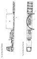
- the Fig. 1a and 1b show in a side view and plan view schematically an example of a prior art semitrailer for transporting a conical, semi-circular precast concrete element L (load), as it is used for the construction of a tower structure of a wind turbine.
- the semitrailer tractor shown comprises a semi-trailer 2 pulled by a semitrailer tractor 1 with a so-called gooseneck 3 (crank) in the front part on which the low-loader 2 is coupled to the tractor 1, an axle assembly 4 consisting of three steered axles in the rear part and one Lademaschine with a Tiefbett-loading area 5 between the gooseneck 3 and the axle assembly 4.
- the precast concrete L is on the low-bed cargo 5 - as in Fig.
- FIG. 1a shows that the low-bed loading area 5 is at a height which is smaller than the diameter of the wheels or tires of the Schuachsan accent 4.
- the precast concrete L claimed almost the entire length of the lowbed loading area. 5
- a larger deep bed loading area is required.
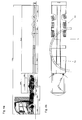
- An example of such a tractor-trailer is in Fig. 2a, 2b shown.
- the larger low-bed loading area 5 'but means a greater overall length and a higher total weight of the trailer.
- a further steered axle may be required.
- the semi-trailer could deviate from the in Fig. 1a, 1b or Fig. 2a, 2b shown embodiment, a telescopic length adjustable (extendable) dock leveler, which allows adjustment of the length of the low-bed cargo area to different large precast concrete parts.
- a telescopic length adjustable (extendable) dock leveler which allows adjustment of the length of the low-bed cargo area to different large precast concrete parts.
- Such telescopic semi-trailers are well known to those skilled in the art and trade magazines. They are manufactured and sold, for example, by the applicant. However, any extension of the semi-trailer truck is subject to limits due to legal requirements as well as stability, weight and cost reasons.
- Raising the cargo bed to a height above the wheels of the rear axle assembly to thereby obtain an increased cargo area while maintaining the same overall length of the flat loader would result in an excessive increase in the overall height of the loaded semi-trailer which is required for road transport of the previously discussed precast concrete products 3800 mm is not practical.
- the present invention seeks to provide a low loader, in particular in the design as a semi-trailer, which provides a sufficiently large cargo area with a relatively simple and lightweight construction, the circular motion segmented, in particular semi-circular, loads, in the Special semicircular prefabricated concrete elements for the construction of a tower structure of a wind turbine allows.
- An inventive low loader for the vertical transport of loads having a circular segment-shaped, in particular semicircular, footprint has a loading surface, which contains an at least in curvature and width of the footprint of a load to be transported corresponding circular ring-shaped bearing surface, and an axle assembly, the at least two in A rigid axle arranged at a predetermined axial spacing, the wheels of which protrude beyond the loading height of the loading surface by wheel recesses spaced apart in the track width direction of the respective rigid axle.
- the annular segment-shaped bearing surface is intended to extend both between the wheels (i.e., the left and right wheels) of the frontward rigid axle in the direction of travel and between the front and rear rigid axles (i.e., the left and right wheels of the front and rear rigid axles).
- a low loader In a low loader according to the invention is a vehicle with a low bed for transporting heavy and / or bulky loads.
- the basic structure, the function and the various embodiments of a low loader are known in the art.
- the low loader according to the invention is designed for the vertical transport of loads with annular segment-shaped, in particular semicircular, footprint.
- the footprint of the load is the ground or underside surface with or on which the respective load is placed on the bed of the low loader, but the footprint does not have to rest on the cargo area.
- loads include in particular conical annular or annular segment-shaped precast concrete elements, such as those used for the construction of a wind turbine tower, with a height of 3600 mm to 3800 mm, a thickness of about 300 mm and, depending on the level at which the respective precast concrete part is installed , an outer radius of 2500 mm to 4850 mm. Due to the large outer diameter, the larger of the prefabricated concrete elements to be transported are designed as circular ring segments, in particular as semicircular rings (also called half shells).
- the bearing surface thus forms part of the loading surface.
- the bearing surface is part of the loading area in the loading area.
- the loading area must therefore cover at least the bearing surface.
- the arc length of the support surface may be smaller than the arc length of the footprint of the load to be transported.
- the load is at one or - as in the Fig. 1b sketched case - both bow ends on the support surface or loading area.
- the bearing surface thus results from the vertically projected onto the loading surface contact surface of the load.
- the loading area may be a continuous flat area or - for example, in the event that the low loader is telescopically - be a possibly composed of partial surfaces flat surface which carries the load to be transported or on which the load to be transported can be parked or arranged.
- a low-loader has in its rear region at least two axle arrangements (having a front and a rear) of the same design, having a predetermined axial spacing.
- the axle arrangement can have one or more further axles, eg rigid axle (s) and / or steered axle (s), in particular a so-called follower steering axle, which in the (forward) direction of travel of the low loader behind the two Rigid axles lies.
- the two rigid axles always form the front axles in (forward) driving direction.
- Such axle arrangements comprising several axles (rigid and / or steered axles) are generally known to the person skilled in the art.
- the spatial extent or space requirement of the two front rigid axles is determined by their tires (single / twin tires and tire size) and their track width.
- the tire size tailored to the weight of the load to be transported determines the size of the wheel recesses receiving the wheels.
- the at least two rigid axles having axle assembly is additionally defined by the axial distance between the two rigid axles. Knowing the tire size, the track width and the track width spacing between the wheels of the rigid axles can be determined by using an appropriate overall width of the flatbed. Alternatively, knowing the overall width of the low loader, the track width and track pitch between the wheels of the rigid axles can be determined by choosing a suitable tire. Analogous considerations apply to the determination of the center distance between the two rigid axles.
- the loading area expands into the region claimed by the two rigid axles, which is limited by the track width of the identical rigid axles, the tires and the center distance between the front and rear rigid axles and therefore calculable or is determinable.
- the circular ring segment-shaped support surface both by lying between the left and right wheels of the front in the direction of travel rigid axle gauge track width range and by lying between the left or right wheels of the front and rear rigid axle center distance range.
- the required track width and the required center distance depending on the dimensions of the load to be transported can be determined by the person skilled in the art such that the annular segment-shaped contact surface of the load (s ) into the limited by the two rigid axles loading area, ie "threading" between the wheels of the two rigid axles.
- the bed located in the area of the two rigid axles comprises a first loading area between the left and right wheels or wheel recesses for the left and right wheels of the front rigid axle and a second loading area between the wheels or wheel recesses for the wheels of the front rigid axle and the wheels or wheel recesses for the wheels of the rear rigid axle.
- the transportable (s) load (s) curvature or outer and inner diameter and thickness
- the inventively provided use of extending in the region of the two rigid axles loading surface as a support surface for the (n) load (s) to be transported over the known over- and Eisenfahrianaladern numerous advantages.
- a significant part of the load is displaced in the direction of the two rigid axles or distributed to the two rigid axles.
- the low loader according to the invention allows a reduction in the total length and thus the weight and the manufacturing or acquisition costs. Deviations from the maximum dimensions provided for in the Highway Code can therefore be kept as low as possible, making special permits easier to reach.
- the centroid of the annular segment-shaped support surface is advantageously at least substantially in the middle of the width of the low loader and the annular ring-shaped bearing surface is advantageous at least substantially symmetrically aligned with respect to a passing through the centroid transverse axis of the low loader.
- the location of the center of gravity of the bearing surface on the bed of the low loader coincides with the position of the projected on the bed volume of gravity of the load.
- the annular-segment-shaped bearing surface is advantageously aligned substantially symmetrically with respect to a passing through the centroid transverse axis of the flatbed trailer, the weight of the load to be transported in the width direction of the trailer is optimally distributed.
- the position of the center of gravity of the arranged in the region of the two rigid axles footprint of the load varies depending on the size of the load to be transported, ie from the outer / inner diameter or outer / inner radius of the load (see Fig. 5b ).
- the lying in (forward) direction of travel of the low loader in front of the two rigid axles or, for example, provided by telescopic extension loading area therefore has a sufficiently large length to order to be arranged before the two rigid axles part of the load can.
- the wheels of the rigid axles can, for example, have twin tires of size 235/75 R 17.55, 245/70 R 17.5, 255/60 R 19.5, 245/70 R 19, 5, 265/70 R 19.5 or 285/70 R 19.5.
- the overall width of the low loader can be extended to an excess width, ie in the range of greater than 2550 mm to a maximum of 3000 mm, advantageously in the range of 2750 mm to 3000 mm, for example at about 2750 mm.
- the width of the cargo bed between the wheels of the rigid axles as measured in the tread width direction may be in the range of 1610 mm to 1650 mm, ideally 1610 mm.
- the length of the loading surface between the wheels of the front rigid axle measured in the axial distance direction is advantageously less than or equal to 900 mm.
- the center distance between the two rigid axles can be greater than or equal to 1360 mm, ideally in the range of 1510 mm to 1650 mm.
- the track widths and center distances specified above take into account not only the space requirements of the wheels or the tires of the rigid axles a required lateral clearance between the wheels and the frame of the trailer and an optionally additionally required distance for attaching fenders or spray protection measures, etc ..
- a low loader according to the invention is advantageously designed as a low-loader semi-trailer with a lower loading surface lying opposite a higher-lying fifth wheel plate and advantageously has a longitudinal telescoping loading bridge.
- a telescopic dock leveler allows flexible adjustment of the length of the loading area to the size of the load to be arranged on the loading area.
- the low loader according to the invention advantageously has, in view of the high weight of the loads to be transported, a steered axle arranged behind the two rigid axles (so-called trailing steering axle).
- An independent invention not claimed in the present application, for which protection may be sought, for example by way of a later patent application claiming the priority of the present application, is a method of carrying a load upright, which an annular segment-shaped, in particular semicircular, footprint has, by means of a low loader according to one of claims 1 to 12.
- the method provides to arrange the load for standing transport on the bed of the low loader so that the footprint of the load between the wheels of in Direction of travel front rigid axle of the trailer and between the left or right wheels of the front and rear rigid axle extends.
- the load can be arranged in particular so that the projected on the bed of the flatbed center of gravity of the footprint of the load in the width center of the trailer.
- the load on the bed of the low loader may be oriented to be symmetrical with respect to a transverse axis of the flatbed passing through the centroid of the footprint of the load projected onto the bed.
- the Fig. 3a and 3b show a first embodiment of a low loader 10 according to the invention in the form of a pulled by a tractor semitrailer.
- the low loader 10 has in a conventional manner, following a higher-lying fifth wheel plate 11, a so-called gooseneck 12 (crank), a low-lying, doppelenzentieleskopierbare loading bridge with a loading area 13 and the rear of the trailer a three axes 15, 16, 17th having axle assembly 14.
- the three axles comprise a front and a rear rigid axle 15, 16 and a steered axle 17 arranged behind the two rigid axles 15, 16 (so-called trailing steering axle).
- the two rigid axles 15, 16 are identical and arranged with an axial distance of about 1650 mm.
- the Fig. 3a and 3b show that each twin-wheeled wheels of each of the three axles 15, 16, 17 each extend through a spaced in the track width direction wheel recess through the loading height of about 560 mm of the cargo area 13 addition.
- the low loader has a total width of 2750 mm.
- the track width of the three axles 15, 16, 17 is about 2190 mm for a tire size 235/75 R 17.55 or 245/70 R 17.5.
- the width of the (first) loading area in the track width direction between the wheels of the front rigid axle 15 is about 1610 mm, and in the axial direction is about 900 mm.
- the loading area 13 is composed of a plurality of partial surfaces, but all at the loading height of 560 mm, ie lie in a plane.
- the loading area 13 according to the invention continues into the areas between the left and right wheels of each of the three axles 15, 16, 17 and over the entire width of the low loader 10 in the Achsabstands Schemee between the three axes 15, 16, 17.
- the low loader 10 according to the invention thus already differs by the extent of the loading area 13 of the well-known over- and Eisenfahrianaladern.
- a standing with the low loader according to the invention in a standing arrangement (see Fig. 1a . 2a ) to be transported load L has a circular segment-shaped, in Fig. 3b semi-circular, footprint L '(bottom or bottom surface) with which the load L is on the bed 13. It should be noted that the footprint 13 does not have to rest on the loading area 13 over the entire area. In the in Fig. 3b sketched example, for example, the footprint L 'of the load L and thus also the load L protrudes at both ends of the bow on the left in (forward) driving direction on the back of the loader 13 of the trailer. In addition, the loading area 13 of several, in Fig. 3b composed of three partial surfaces.
- the loading surface 13 provides a circular-segment-segment-shaped support surface 13 'corresponding at least in curvature and width of the contact surface L' of the load L, which in Fig. 3b indicated by dashed lines.
- the bearing surface 13 ' corresponds to the footprint 13 projected footprint L' of the load.
- the support surface 13 ' is located as a partial surface of the loading area 13 in the loading area 13. It extends through both the track width range between the wheels of the front in the direction of travel rigid axle 15 and by the Achsabstands Scheme between the front and rear rigid axle 15, 16 therethrough Fig. 3b is shown.
- the Fig. 3b indicates that the loading area 13 may be larger than the bearing surface 13 'contained in the loading area 13.
- the footprint of the load L greater than the Support surface 13 '.
- the load L and thus the footprint L 'of the load L projects in the (forward) direction of travel of the flatbed truck 10 on the left side laterally beyond the loading area 13. Due to the laterally projecting footprint L ', the arc length of lying in the bed 13, circular-segment-shaped support surface 13' is smaller than the arc length of the semicircular footprint L '.
- the centroid FSP of the annular segment-shaped support surface 13 'in the width center of the flatbed 10 (on the in Fig. 3b dash-dotted registered longitudinal center axis of the flatbed 10) and is the annular segment-shaped support surface 13 'with respect to a passing through the centroid FSP (in Fig. 3b dash-dotted registered) transverse axis Q of the low loader 10 symmetrically aligned.
- the lateral projection is therefore the same at the two arc ends of the footprint L 'of the load L.
- the position of the center of gravity FSP of the support surface 13 'on the loading surface 13 of the low loader 10 coincides with the position of the projected on the bed 13 (not shown) volume of gravity of the load L.
- the inventively provided use of extending in the region of the two rigid axles 15, 16 loading area 13 as support surface 13 'for the load L to be transported arise over the known over- and Eisenfahrianaladern numerous advantages.
- a not inconsiderable part of the load L is displaced in the direction of the two rigid axles 15, 16 or distributed to the two rigid axles 15, 16.
- the low loader according to the invention allows a reduction in the total length and thus the weight and the manufacturing or acquisition costs. Deviations from the maximum dimensions provided for in the Highway Code can therefore be kept as low as possible, making special permits easier to reach.
- the Fig. 4a, 4b show the low loader 10 Fig. 3a, 3b in a state with a size of the L to be transported correspondingly extended loading area 13.
- Die Fig. 5a, 5b show the low loader 10 out Fig. 3a, 3b In a state with extended loading area 13, which provides space for different sized loads space.
- the telescopic design of the low loader therefore allows a flexible adjustment of the length of the bed 13 and the total length of the low loader 10 to the size of the load to be transported L.
- the Fig. 6a, 6b show a second embodiment of a low loader 100 according to the invention in the form of a pulled by a tractor semitrailer.
- the low loader 100 differs from that with the help of Fig. 3a to 5b presented low loader 10 of the first embodiment only in that it is designed to be simply telescopic lengthened. Apart from that, the low loader is similar to that of the first embodiment.
- the low loader according to the invention although designed for the vertical transport of loads that have a circular ring segment-shaped, in particular semicircular, footprint, but he can of course also use for the transport of annular loads, as in Fig. 6c, 6d is shown.
- the invention relates to a low loader for the vertical transport of a load having a circular segment-shaped, in particular semicircular, footprint, with a loading surface, which contains an at least in curvature and width of the footprint corresponding circular ring-shaped support surface, and an axle assembly, the two arranged at a predetermined center distance Rigid axles comprises, wherein the wheels of each rigid axle protrude through spaced in the track width direction of the respective rigid axle Radaussparieux beyond the loading height of the loading area.
- the invention extends or "meandering" the annular segment-shaped support surface both between the left and right wheels of the front in the direction of travel rigid axle and between the left and right wheels of the front and rear rigid axle.
- the center of gravity of the annular segment-shaped support surface is at least substantially in the middle of the width of the low loader and the annular segment-shaped support surface is aligned at least substantially symmetrically with respect to a passing through the centroid transverse axis of the trailer.
Landscapes
- Engineering & Computer Science (AREA)
- Transportation (AREA)
- Mechanical Engineering (AREA)
- Chemical & Material Sciences (AREA)
- Combustion & Propulsion (AREA)
- Health & Medical Sciences (AREA)
- Public Health (AREA)
- Handcart (AREA)
Applications Claiming Priority (1)
| Application Number | Priority Date | Filing Date | Title |
|---|---|---|---|
| DE202015102555.6U DE202015102555U1 (de) | 2015-05-19 | 2015-05-19 | Tieflader zum transport kreisringsegmentförmiger lasten |
Publications (1)
| Publication Number | Publication Date |
|---|---|
| EP3098142A1 true EP3098142A1 (fr) | 2016-11-30 |
Family
ID=53801676
Family Applications (1)
| Application Number | Title | Priority Date | Filing Date |
|---|---|---|---|
| EP16168692.8A Withdrawn EP3098142A1 (fr) | 2015-05-19 | 2016-05-09 | Camionnette surbaissee pour le transport de charges en forme de segment de couronne |
Country Status (2)
| Country | Link |
|---|---|
| EP (1) | EP3098142A1 (fr) |
| DE (1) | DE202015102555U1 (fr) |
Cited By (1)
| Publication number | Priority date | Publication date | Assignee | Title |
|---|---|---|---|---|
| WO2022127096A1 (fr) * | 2020-12-15 | 2022-06-23 | 中铁上海工程局集团有限公司 | Dispositif de fixation pour dalles et dispositif de transport |
Citations (5)
| Publication number | Priority date | Publication date | Assignee | Title |
|---|---|---|---|---|
| US2955837A (en) * | 1959-10-23 | 1960-10-11 | William W Bachtell | Trailer construction |
| US4119224A (en) * | 1976-02-12 | 1978-10-10 | David Moody | Vehicle of adjustable width |
| US5924754A (en) * | 1997-05-30 | 1999-07-20 | E-Z Trail, Inc. | Adjustable dimension trailer |
| DE19924889A1 (de) * | 1998-06-03 | 2000-03-23 | Goldhofer Fahrzeugwerk | Vorrichtung zum Transportieren von sperrigen, insbesondere runden oder rechteckigen, Bauteilen großer Abmessungen und Gewichts |
| DE102011076648A1 (de) | 2011-05-27 | 2012-11-29 | Max Bögl Wind AG | Verfahren zum Errichten einer Windkraftanlage |
-
2015
- 2015-05-19 DE DE202015102555.6U patent/DE202015102555U1/de not_active Expired - Lifetime
-
2016
- 2016-05-09 EP EP16168692.8A patent/EP3098142A1/fr not_active Withdrawn
Patent Citations (5)
| Publication number | Priority date | Publication date | Assignee | Title |
|---|---|---|---|---|
| US2955837A (en) * | 1959-10-23 | 1960-10-11 | William W Bachtell | Trailer construction |
| US4119224A (en) * | 1976-02-12 | 1978-10-10 | David Moody | Vehicle of adjustable width |
| US5924754A (en) * | 1997-05-30 | 1999-07-20 | E-Z Trail, Inc. | Adjustable dimension trailer |
| DE19924889A1 (de) * | 1998-06-03 | 2000-03-23 | Goldhofer Fahrzeugwerk | Vorrichtung zum Transportieren von sperrigen, insbesondere runden oder rechteckigen, Bauteilen großer Abmessungen und Gewichts |
| DE102011076648A1 (de) | 2011-05-27 | 2012-11-29 | Max Bögl Wind AG | Verfahren zum Errichten einer Windkraftanlage |
Cited By (1)
| Publication number | Priority date | Publication date | Assignee | Title |
|---|---|---|---|---|
| WO2022127096A1 (fr) * | 2020-12-15 | 2022-06-23 | 中铁上海工程局集团有限公司 | Dispositif de fixation pour dalles et dispositif de transport |
Also Published As
| Publication number | Publication date |
|---|---|
| DE202015102555U1 (de) | 2015-07-23 |
Similar Documents
| Publication | Publication Date | Title |
|---|---|---|
| EP3653435B1 (fr) | Véhicule destiné au transport d'un article à transporter allongé | |
| DE212013000022U1 (de) | Anordnung in einer Forstmaschine und mit dementsprechender Anordnung ausgerüstete Forstmaschine | |
| DE202012010545U1 (de) | Schwerlast-Transportfahrzeug zum Transport eines länglichen Objekts | |
| EP2917070A2 (fr) | Véhicule de transport de charges lourdes servant au transport d'un objet allongé | |
| DE60104955T2 (de) | Rekonfigurierbarer Krantrager | |
| DE202008009572U1 (de) | Fahrzeuganhänger | |
| DE102012021613A1 (de) | Schwerlast-Transportfahrzeug zum Transport eines länglichen Objekts | |
| EP3326892A1 (fr) | Remorque de transport pourvue de châssis et d'au moins une plate-forme au sol | |
| EP3098142A1 (fr) | Camionnette surbaissee pour le transport de charges en forme de segment de couronne | |
| EP0214163B1 (fr) | Chassis d'un vehicule poids lourd, en particulier d'une grue mobile a plusieurs essieux | |
| DE102014006273A1 (de) | Abstützung | |
| EP1122151B1 (fr) | Véhicule à plateau de chargement surbaissé extensible | |
| EP3150428B1 (fr) | Véhicule de transport de véhicules automobiles avec surface de transport modifiable et procédé de chargement d'un tel véhicule de transport | |
| CH673988A5 (fr) | ||
| DE102014008720B4 (de) | Schwerlastfahrzeug mit Staplerfunktion | |
| EP3156310A1 (fr) | Véhicule auxiliaire agricole sans entraînement | |
| DE102016111308A1 (de) | Fahrgestellanordnung und Landfahrzeug | |
| DE102007049673A1 (de) | Verfahren zum Bergen von Flugzeugen und Flugzeugbergeheber | |
| EP1366971B1 (fr) | Tracteur de semi-remorque | |
| EP3412620B1 (fr) | Grue de construction et système de grue de construction | |
| EP3461785B1 (fr) | Grue | |
| DE202016101503U1 (de) | Aufbaukran und Aufbaukransystem | |
| DE102020118775A1 (de) | Fahrbarer Kran mit Abstützvorrichtung | |
| DE202016100825U1 (de) | Fahrgestell | |
| EP3393963B1 (fr) | Grue modulaire, unité de transport pour grue modulaire et procédé de fonctionnement d'une telle grue |
Legal Events
| Date | Code | Title | Description |
|---|---|---|---|
| PUAI | Public reference made under article 153(3) epc to a published international application that has entered the european phase |
Free format text: ORIGINAL CODE: 0009012 |
|
| 17P | Request for examination filed |
Effective date: 20160509 |
|
| AK | Designated contracting states |
Kind code of ref document: A1 Designated state(s): AL AT BE BG CH CY CZ DE DK EE ES FI FR GB GR HR HU IE IS IT LI LT LU LV MC MK MT NL NO PL PT RO RS SE SI SK SM TR |
|
| AX | Request for extension of the european patent |
Extension state: BA ME |
|
| 17Q | First examination report despatched |
Effective date: 20190107 |
|
| GRAP | Despatch of communication of intention to grant a patent |
Free format text: ORIGINAL CODE: EPIDOSNIGR1 |
|
| INTG | Intention to grant announced |
Effective date: 20190913 |
|
| STAA | Information on the status of an ep patent application or granted ep patent |
Free format text: STATUS: THE APPLICATION IS DEEMED TO BE WITHDRAWN |
|
| 18D | Application deemed to be withdrawn |
Effective date: 20200124 |