EP3147419B1 - Connecteur - Google Patents
Connecteur Download PDFInfo
- Publication number
- EP3147419B1 EP3147419B1 EP15186790.0A EP15186790A EP3147419B1 EP 3147419 B1 EP3147419 B1 EP 3147419B1 EP 15186790 A EP15186790 A EP 15186790A EP 3147419 B1 EP3147419 B1 EP 3147419B1
- Authority
- EP
- European Patent Office
- Prior art keywords
- fittings
- connector according
- fitting
- wedged
- keys
- Prior art date
- Legal status (The legal status is an assumption and is not a legal conclusion. Google has not performed a legal analysis and makes no representation as to the accuracy of the status listed.)
- Active
Links
- 210000001145 finger joint Anatomy 0.000 description 26
- 239000002023 wood Substances 0.000 description 10
- 230000000295 complement effect Effects 0.000 description 7
- 238000003801 milling Methods 0.000 description 7
- 239000003292 glue Substances 0.000 description 3
- 239000000463 material Substances 0.000 description 3
- 229910000831 Steel Inorganic materials 0.000 description 2
- 229910052782 aluminium Inorganic materials 0.000 description 2
- XAGFODPZIPBFFR-UHFFFAOYSA-N aluminium Chemical compound [Al] XAGFODPZIPBFFR-UHFFFAOYSA-N 0.000 description 2
- 229910052751 metal Inorganic materials 0.000 description 2
- 239000002184 metal Substances 0.000 description 2
- 239000010959 steel Substances 0.000 description 2
- 241000196324 Embryophyta Species 0.000 description 1
- 244000261422 Lysimachia clethroides Species 0.000 description 1
- HCHKCACWOHOZIP-UHFFFAOYSA-N Zinc Chemical compound [Zn] HCHKCACWOHOZIP-UHFFFAOYSA-N 0.000 description 1
- 238000010521 absorption reaction Methods 0.000 description 1
- 230000006978 adaptation Effects 0.000 description 1
- 238000004026 adhesive bonding Methods 0.000 description 1
- 239000011230 binding agent Substances 0.000 description 1
- 230000005540 biological transmission Effects 0.000 description 1
- 150000001875 compounds Chemical class 0.000 description 1
- 238000010276 construction Methods 0.000 description 1
- 230000002349 favourable effect Effects 0.000 description 1
- 238000007373 indentation Methods 0.000 description 1
- 238000003780 insertion Methods 0.000 description 1
- 230000037431 insertion Effects 0.000 description 1
- 238000009434 installation Methods 0.000 description 1
- 238000012986 modification Methods 0.000 description 1
- 230000004048 modification Effects 0.000 description 1
- 230000035515 penetration Effects 0.000 description 1
- 239000007787 solid Substances 0.000 description 1
- 229910052725 zinc Inorganic materials 0.000 description 1
- 239000011701 zinc Substances 0.000 description 1
Images


Classifications
-
- E—FIXED CONSTRUCTIONS
- E04—BUILDING
- E04B—GENERAL BUILDING CONSTRUCTIONS; WALLS, e.g. PARTITIONS; ROOFS; FLOORS; CEILINGS; INSULATION OR OTHER PROTECTION OF BUILDINGS
- E04B1/00—Constructions in general; Structures which are not restricted either to walls, e.g. partitions, or floors or ceilings or roofs
- E04B1/18—Structures comprising elongated load-supporting parts, e.g. columns, girders, skeletons
- E04B1/26—Structures comprising elongated load-supporting parts, e.g. columns, girders, skeletons the supporting parts consisting of wood
- E04B1/2604—Connections specially adapted therefor
- E04B2001/2628—Interlocking connectors, e.g. with hooks or dovetails, added to the elongated wooden members
-
- E—FIXED CONSTRUCTIONS
- E04—BUILDING
- E04B—GENERAL BUILDING CONSTRUCTIONS; WALLS, e.g. PARTITIONS; ROOFS; FLOORS; CEILINGS; INSULATION OR OTHER PROTECTION OF BUILDINGS
- E04B1/00—Constructions in general; Structures which are not restricted either to walls, e.g. partitions, or floors or ceilings or roofs
- E04B1/18—Structures comprising elongated load-supporting parts, e.g. columns, girders, skeletons
- E04B1/26—Structures comprising elongated load-supporting parts, e.g. columns, girders, skeletons the supporting parts consisting of wood
- E04B1/2604—Connections specially adapted therefor
- E04B2001/2664—Connections specially adapted therefor using a removable key
Definitions
- the present invention relates to a connector for two workpieces, with two fittings, which are fastened with their one side to each one of the workpieces and with their other sides abuttable to each other, and two clamping jaws which grip the fittings at diametral ends and by means of at least a threaded rod against each other are tensioned, which runs approximately parallel to said other sides.
- Such wood connectors are marketed, for example, by the company Knapp GmbH, Euratsfeld, Austria, under the brand name Megant® and are particularly suitable for the construction of heavy-duty joints in timber engineering, for example for connecting main, secondary and / or cross members, cross trains, trusses, supports or the like.
- the fittings and jaws are usually made of metal, such as high-strength aluminum, and the workpieces to be joined from wood, such as glued laminated timber (BSH), laminated beams, etc.
- BSH glued laminated timber
- One of the workpieces may also be a concrete beam, a wall or a floor, what a carrier to be connected by means of the connector.
- a connector of the aforementioned type which according to the invention is characterized in that said one side of at least one fitting, preferably both fittings, is provided with a finger jointing profile.
- the fitting In accordance with complementary complementary finger jointing of the workpiece to which the fitting is attached, so that a high-strength finger joint between fitting and workpiece can be created, which achieves an intimate, positive and non-positive connection of the connector to the workpiece.
- the fitting can optionally be glued to the workpiece, to achieve an additional bond between the two parts.
- the connector according to the invention is also particularly suitable for workpieces made of fast-growing woods, which have a lower bulk density and thus lower strength and thus provide less support for screwing the fitting.
- the connector according to the invention can be here on an increase in the number of screws, which would otherwise be required to compensate for the lower density, be dispensed with.
- the number of screws required to fasten the fittings can be reduced, thus saving weight and costs. Even costly oblique screwing can be reduced or replaced by simple to produce straight fittings.
- the finger joints of the finger joint profile run approximately normal to the threaded rod, so that they can absorb or support tensile and compressive forces in the direction of the threaded rod (s) well.
- flank angles of the finger joints of the finger joint profile are preferably self-locking in order to ensure a good absorption of force.
- a particularly advantageous embodiment of the invention is characterized in that the finger jointing profile is formed in an adapter plate, which is inserted into said one side of a fitting or mounted thereon.
- the connector of the invention can thereby be modularly constructed, stored and used. Different adapter plates with different finger joint profiles can be with one and the same Fuse body can be combined to allow adaptation to different workpiece materials, such as wood qualities. Thus, adapter plates with different finger joint profiles in terms of tine length, zinc pitch, tine play, flank angle, etc., depending on the workpiece and application can be used.
- the adapter plate can be plugged together with the rest of fitting, latched, locked, glued and / or screwed.
- the tips of the finger joints can protrude in a plane from the fitting, which allows a simple, straight milling of the finger joint in the workpiece to be connected.
- the tips of the finger joints can protrude like a cylinder segment from the fitting, whereby, for example, side milling cutters can be used to produce the complementary finger joint in the workpiece to be connected.
- the fittings are additionally provided with holes for screwing to the workpieces.
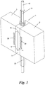
- Fig. 1 shows a connector 1 for two workpieces 2, 3.
- the workpieces 2, 3 are, for example, columns, pillars, main, side or cross member of a building, eg roof, or the like.
- the connector 1 is mainly for workpieces 2, 3 from Wood, for example wood beams made of solid wood, glued laminated timber (BSH), glued laminated wood ("glue binder”), etc.
- BSH glued laminated timber
- glue binder glued laminated wood
- One (or both) of the workpieces 2, 3 may also be made of a different material, such as concrete, masonry, etc., and Connector 1 can also be used, for example, to connect a wooden support 2 to a building part 3.
- the connector 1 is preferably made of metal, e.g. Steel and / or high-strength aluminum, but could be made of other materials such as wood or plastic at low load requirements.
- the connector 1 comprises two fittings 4, 5 which can be fastened with their one side 6, 7 to the respective workpiece 2, 3, as explained in more detail later. With their other sides 8, 9, the fittings 4, 5 can be brought into contact with each other.
- the plant pages 8, 9 can as shown plan or complementarily shaped to ensure a good mutual investment.
- Each clamping jaws 10, 11 has a keyway 12 for receiving the abutting, complementary wedge-shaped ends 14, 15 and 16, 17 of the fittings 4, 5.
- a threaded rod 18 which is received in mutually facing half-chamfers 19, 20 in the sides 8, 9 of the fittings 4, 5 and so passes through the abutting fittings 4, 5 approximately centrally.
- nuts 21, 22, which are mounted on the threaded rod 18 from the outside and press against the outside of the clamping jaws 10, 11, they can be clamped against each other.
- the clamping jaws 10, 11 could be provided with opposing internal threads 23, so that one or both nuts 21, 22 can be saved.
- the fittings 4, 5 - and optionally also the clamping jaws 10, 11 - are provided with holes 24 through which screws 25 can be passed and screwed into the workpieces 2, 3.
- each finger joint profile 26, 27 preferably run approximately normal to the / the threaded rod (s) 28, so that in the in the Fig. 1 and 2 shown exemplary installation position with vertical threaded rod 18, the finger joints 30 are approximately horizontal (see Fig. 2 ). This allows them to record vertical tension and pressure, ie vertical shear forces between the workpieces 2, 3, particularly well.
- the flank angles of the finger joints 30 of the finger splines 26, 27 are preferably also chosen to be flat so that they are self-locking.
- the sides 6, 7 or finger joint profiles 26, 27 can also be glued to the workpieces 2, 3 or their finger joint milling cuts 28, 29.
- FIGS. 5 and 6 show two different configurations of the finger joint profiles 26, 27.
- Fig. 6 are cylindrical segments of the fitting 4, 5 projecting finger joints 30 of the finger joint profiles 26, 27 shown.
- This embodiment is suitable for finger joint milling 28, 29, which are incorporated by means of circular disk milling in the workpieces 2, 3.
- each fitting 4, 5 can be designed not only in one piece, but also in several parts.
- the finger jointing profile 26, 27 may be formed in a separate adapter plate 31, which in the workpiece 2, 3 facing side 8, 9 of the respective fitting 4, 5 is used or mounted on this.
- the adapter plate 31 can be screwed, glued or otherwise connected to the remaining fitting ("fitting base body") 32, if desired also detachable or modular exchangeable. It also mutually complementary paragraphs, stages or the like. 33 or tongue and groove or dovetail joints 34 are provided for insertion, latching, latching, etc. between the adapter plate 31 and the base body 32.
- the adapter plate 31 can be connected by means of separate screws with the base body 32 or by means of the same screws 25, which fix the fitting 4, 5 on the workpiece 2, 3.
- the optional paragraphs 33 and 34 compounds for additional power transmission between adapter plate 31 and body 32 are used.
- fittings 4, 5 can be equipped with a finger joint profile 26, 27, e.g. if the other fitting 4, 5 for mounting on a concrete or steel beams, masonry od. Like. Without complementary finger joint milling is determined.
Claims (10)
- Connecteur (1) pour deux pièces d'oeuvre (2, 3), comprenant deux armatures (4, 5) qui peuvent être fixées chaque fois à l'une des pièces d'oeuvre (2, 3) à l'aide d'un de leurs côtés (6, 7) et peuvent être mises en appui l'une contre l'autre à l'aide de leur autre côté (8, 9), et
deux mâchoires de serrage (10, 11), lesquelles prennent en prise les armatures (4, 5) à des extrémités diamétrales (14, 15 ; 16, 17) et peuvent être serrées l'une contre l'autre au moyen d'au moins une tige filetée (18) qui s'étend sensiblement parallèlement par rapport aux dits autres côtés (8, 9), caractérisé en ce
que ledit un côté (6, 7) d'au moins une armature (4, 5), de préférence des deux armatures (4, 5), est muni avec un profil à dents clavettes (26, 27). - Connecteur selon la revendication 1, caractérisé en ce que les dents clavettes (30) du profil à dents clavettes (26, 27) s'étendent à peu près normalement par rapport à la tige filetée (18).
- Connecteur selon la revendication 1 ou 2, caractérisé en ce que les angles des flancs des dents clavettes (30) du profil à dents clavettes (26, 27) sont autobloquants.
- Connecteur selon l'une des revendications 1 à 3, caractérisé en ce que le profil à dents clavettes (26, 27) est mis en place dans une plaque d'adaptateur (31) laquelle est insérée dans ledit un côté (6, 7) d'une armature (4, 5) ou est montée sur ceci.
- Connecteur selon la revendication 4, caractérisé en ce que la plaque d'adaptateur (31) peut être vissée avec l'armature restante (32).
- Connecteur selon l'une des revendications 1 à 5, caractérisé en ce que les pointes des dents clavettes (30) dépassent de l'armature (4, 5) dans un plan.
- Connecteur selon l'une des revendications 1 à 5, caractérisé en ce que les pointes des dents clavettes (30) dépassent de l'armature (4, 5) sous la forme d'un segment d'un cylindre.
- Connecteur selon l'une des revendications 1 à 7, caractérisé en ce que les armatures (4, 5) sont munies d'alésages (24) pour le vissage avec les pièces d'oeuvre (2, 3).
- Connecteur selon l'une des revendications 1 à 8, caractérisé en ce que lesdites extrémités (14 - 17) des armatures (4, 5) sont en forme de cales et chaque mâchoire de serrage (10, 11) présente une rainure en forme de cale (12) pour la reception de deux extrémités (14, 15 ; 16,17) en forme de cales reposantes l'une contre l'autre.
- Connecteur selon l'une des revendications 1 à 9, caractérisé en ce que l'au moins une tige filetée (18) est admise dans des demies gorges (29) desdits autres côtés (8, 9) opposées l'une à l'autre.
Priority Applications (2)
| Application Number | Priority Date | Filing Date | Title |
|---|---|---|---|
| EP15186790.0A EP3147419B1 (fr) | 2015-09-25 | 2015-09-25 | Connecteur |
| PCT/EP2016/071643 WO2017050615A1 (fr) | 2015-09-25 | 2016-09-14 | Raccord |
Applications Claiming Priority (1)
| Application Number | Priority Date | Filing Date | Title |
|---|---|---|---|
| EP15186790.0A EP3147419B1 (fr) | 2015-09-25 | 2015-09-25 | Connecteur |
Publications (2)
| Publication Number | Publication Date |
|---|---|
| EP3147419A1 EP3147419A1 (fr) | 2017-03-29 |
| EP3147419B1 true EP3147419B1 (fr) | 2018-04-11 |
Family
ID=54207332
Family Applications (1)
| Application Number | Title | Priority Date | Filing Date |
|---|---|---|---|
| EP15186790.0A Active EP3147419B1 (fr) | 2015-09-25 | 2015-09-25 | Connecteur |
Country Status (2)
| Country | Link |
|---|---|
| EP (1) | EP3147419B1 (fr) |
| WO (1) | WO2017050615A1 (fr) |
Families Citing this family (2)
| Publication number | Priority date | Publication date | Assignee | Title |
|---|---|---|---|---|
| EP3348722B1 (fr) * | 2017-01-13 | 2020-04-01 | Knapp GmbH | Élément de liaison et dispositif d'accouplement de composants verticaux |
| EP4350094A1 (fr) * | 2022-10-07 | 2024-04-10 | Rotho Blaas GmbH/Srl | Système de liaison pour relier des éléments de construction à au moins un élément de construction en bois |
Family Cites Families (3)
| Publication number | Priority date | Publication date | Assignee | Title |
|---|---|---|---|---|
| DE102005014900A1 (de) * | 2005-04-01 | 2006-10-05 | Induo Gesellschaft Zur Verwertung Von Schutzrechten Mbh & Co Kg | Verbundanker zum Verbinden mindestens zweier Bauelemente und System von miteinander verbundenen Bauelementen |
| DE102008010612A1 (de) * | 2008-02-22 | 2009-09-03 | Kratzer, Daniel | Verbindungskörper |
| DE202013100120U1 (de) * | 2013-01-10 | 2014-04-11 | SCHÜCO International KG | T-Verbindung für eine Pfosten-Riegel-Konstruktion |
-
2015
- 2015-09-25 EP EP15186790.0A patent/EP3147419B1/fr active Active
-
2016
- 2016-09-14 WO PCT/EP2016/071643 patent/WO2017050615A1/fr active Application Filing
Non-Patent Citations (1)
| Title |
|---|
| None * |
Also Published As
| Publication number | Publication date |
|---|---|
| EP3147419A1 (fr) | 2017-03-29 |
| WO2017050615A1 (fr) | 2017-03-30 |
Similar Documents
| Publication | Publication Date | Title |
|---|---|---|
| EP1007809B1 (fr) | Dispositif de renfort pour structures porteuses | |
| EP3456892B1 (fr) | Connecteur pour deux pièces à assembler | |
| EP3366855B1 (fr) | Élément de liaison, support et dispositif d'accouplement de composants verticaux | |
| AT5013U1 (de) | Montagegerät zum setzen von befestigern beim verbinden von einander an ihren enden überlappenden holzbalken | |
| EP1729018B1 (fr) | Système d'assemblage de profilés | |
| DE102008029935B3 (de) | Verbindungseinrichtung | |
| EP3433440A1 (fr) | Procédé et ensemble d'assemblage pour l'assemblage de poutres en matériau dérivé du bois | |
| DE102010035330B4 (de) | Vorrichtung zur Befestigung eines Bohrständers für eine Bohrmaschine | |
| EP3147419B1 (fr) | Connecteur | |
| DE10359761A1 (de) | Klemmvorrichtung | |
| DE102015002272B4 (de) | Hohlprofilverbindung zum Verlängern oder rechtwinkligen Verbinden von rechteckige Querschnitte aufweisenden Hohlprofilen | |
| EP1699986B1 (fr) | Construction de parois en bois, du type a madriers en blocs | |
| CH702591A2 (de) | Vorrichtung zur Montage von verschraubbaren Rohrschellen. | |
| DE202011003315U1 (de) | Verbindungsvorrichtung | |
| AT506192B1 (de) | Verbindungselement | |
| DE202014005734U1 (de) | Bandaufnahmeelement | |
| DE10027572C2 (de) | Spannzwinge | |
| EP2604868B1 (fr) | Dispositif et procédé destinés à la liaison de composants | |
| DE3506455C2 (fr) | ||
| EP1605172B1 (fr) | Ferrure pour assembler un élément structural allongé et un élément structural plat | |
| DE602006001035T2 (de) | Befestigungssystem für Profile | |
| CH698907B1 (de) | Befestigungselement für Bauteile. | |
| DE202005009746U1 (de) | Spanneinrichtung | |
| DE19700952C2 (de) | Vorrichtung zur Verankerung von Gerüsten | |
| AT12448U1 (de) | Verbindungsvorrichtung |
Legal Events
| Date | Code | Title | Description |
|---|---|---|---|
| PUAI | Public reference made under article 153(3) epc to a published international application that has entered the european phase |
Free format text: ORIGINAL CODE: 0009012 |
|
| AK | Designated contracting states |
Kind code of ref document: A1 Designated state(s): AL AT BE BG CH CY CZ DE DK EE ES FI FR GB GR HR HU IE IS IT LI LT LU LV MC MK MT NL NO PL PT RO RS SE SI SK SM TR |
|
| AX | Request for extension of the european patent |
Extension state: BA ME |
|
| 17P | Request for examination filed |
Effective date: 20170928 |
|
| RBV | Designated contracting states (corrected) |
Designated state(s): AL AT BE BG CH CY CZ DE DK EE ES FI FR GB GR HR HU IE IS IT LI LT LU LV MC MK MT NL NO PL PT RO RS SE SI SK SM TR |
|
| GRAP | Despatch of communication of intention to grant a patent |
Free format text: ORIGINAL CODE: EPIDOSNIGR1 |
|
| INTG | Intention to grant announced |
Effective date: 20171110 |
|
| GRAS | Grant fee paid |
Free format text: ORIGINAL CODE: EPIDOSNIGR3 |
|
| GRAA | (expected) grant |
Free format text: ORIGINAL CODE: 0009210 |
|
| AK | Designated contracting states |
Kind code of ref document: B1 Designated state(s): AL AT BE BG CH CY CZ DE DK EE ES FI FR GB GR HR HU IE IS IT LI LT LU LV MC MK MT NL NO PL PT RO RS SE SI SK SM TR |
|
| REG | Reference to a national code |
Ref country code: GB Ref legal event code: FG4D Free format text: NOT ENGLISH |
|
| REG | Reference to a national code |
Ref country code: CH Ref legal event code: EP |
|
| REG | Reference to a national code |
Ref country code: AT Ref legal event code: REF Ref document number: 988176 Country of ref document: AT Kind code of ref document: T Effective date: 20180415 |
|
| REG | Reference to a national code |
Ref country code: CH Ref legal event code: NV Representative=s name: HEPP WENGER RYFFEL AG, CH |
|
| REG | Reference to a national code |
Ref country code: IE Ref legal event code: FG4D Free format text: LANGUAGE OF EP DOCUMENT: GERMAN |
|
| REG | Reference to a national code |
Ref country code: DE Ref legal event code: R096 Ref document number: 502015003804 Country of ref document: DE |
|
| REG | Reference to a national code |
Ref country code: NL Ref legal event code: MP Effective date: 20180411 |
|
| REG | Reference to a national code |
Ref country code: LT Ref legal event code: MG4D |
|
| REG | Reference to a national code |
Ref country code: FR Ref legal event code: PLFP Year of fee payment: 4 |
|
| PG25 | Lapsed in a contracting state [announced via postgrant information from national office to epo] |
Ref country code: NL Free format text: LAPSE BECAUSE OF FAILURE TO SUBMIT A TRANSLATION OF THE DESCRIPTION OR TO PAY THE FEE WITHIN THE PRESCRIBED TIME-LIMIT Effective date: 20180411 |
|
| PG25 | Lapsed in a contracting state [announced via postgrant information from national office to epo] |
Ref country code: SE Free format text: LAPSE BECAUSE OF FAILURE TO SUBMIT A TRANSLATION OF THE DESCRIPTION OR TO PAY THE FEE WITHIN THE PRESCRIBED TIME-LIMIT Effective date: 20180411 Ref country code: ES Free format text: LAPSE BECAUSE OF FAILURE TO SUBMIT A TRANSLATION OF THE DESCRIPTION OR TO PAY THE FEE WITHIN THE PRESCRIBED TIME-LIMIT Effective date: 20180411 Ref country code: AL Free format text: LAPSE BECAUSE OF FAILURE TO SUBMIT A TRANSLATION OF THE DESCRIPTION OR TO PAY THE FEE WITHIN THE PRESCRIBED TIME-LIMIT Effective date: 20180411 Ref country code: BG Free format text: LAPSE BECAUSE OF FAILURE TO SUBMIT A TRANSLATION OF THE DESCRIPTION OR TO PAY THE FEE WITHIN THE PRESCRIBED TIME-LIMIT Effective date: 20180711 Ref country code: FI Free format text: LAPSE BECAUSE OF FAILURE TO SUBMIT A TRANSLATION OF THE DESCRIPTION OR TO PAY THE FEE WITHIN THE PRESCRIBED TIME-LIMIT Effective date: 20180411 Ref country code: NO Free format text: LAPSE BECAUSE OF FAILURE TO SUBMIT A TRANSLATION OF THE DESCRIPTION OR TO PAY THE FEE WITHIN THE PRESCRIBED TIME-LIMIT Effective date: 20180711 Ref country code: LT Free format text: LAPSE BECAUSE OF FAILURE TO SUBMIT A TRANSLATION OF THE DESCRIPTION OR TO PAY THE FEE WITHIN THE PRESCRIBED TIME-LIMIT Effective date: 20180411 Ref country code: PL Free format text: LAPSE BECAUSE OF FAILURE TO SUBMIT A TRANSLATION OF THE DESCRIPTION OR TO PAY THE FEE WITHIN THE PRESCRIBED TIME-LIMIT Effective date: 20180411 |
|
| PG25 | Lapsed in a contracting state [announced via postgrant information from national office to epo] |
Ref country code: GR Free format text: LAPSE BECAUSE OF FAILURE TO SUBMIT A TRANSLATION OF THE DESCRIPTION OR TO PAY THE FEE WITHIN THE PRESCRIBED TIME-LIMIT Effective date: 20180712 Ref country code: HR Free format text: LAPSE BECAUSE OF FAILURE TO SUBMIT A TRANSLATION OF THE DESCRIPTION OR TO PAY THE FEE WITHIN THE PRESCRIBED TIME-LIMIT Effective date: 20180411 Ref country code: RS Free format text: LAPSE BECAUSE OF FAILURE TO SUBMIT A TRANSLATION OF THE DESCRIPTION OR TO PAY THE FEE WITHIN THE PRESCRIBED TIME-LIMIT Effective date: 20180411 Ref country code: LV Free format text: LAPSE BECAUSE OF FAILURE TO SUBMIT A TRANSLATION OF THE DESCRIPTION OR TO PAY THE FEE WITHIN THE PRESCRIBED TIME-LIMIT Effective date: 20180411 |
|
| PG25 | Lapsed in a contracting state [announced via postgrant information from national office to epo] |
Ref country code: PT Free format text: LAPSE BECAUSE OF FAILURE TO SUBMIT A TRANSLATION OF THE DESCRIPTION OR TO PAY THE FEE WITHIN THE PRESCRIBED TIME-LIMIT Effective date: 20180813 |
|
| REG | Reference to a national code |
Ref country code: DE Ref legal event code: R097 Ref document number: 502015003804 Country of ref document: DE |
|
| PG25 | Lapsed in a contracting state [announced via postgrant information from national office to epo] |
Ref country code: RO Free format text: LAPSE BECAUSE OF FAILURE TO SUBMIT A TRANSLATION OF THE DESCRIPTION OR TO PAY THE FEE WITHIN THE PRESCRIBED TIME-LIMIT Effective date: 20180411 Ref country code: CZ Free format text: LAPSE BECAUSE OF FAILURE TO SUBMIT A TRANSLATION OF THE DESCRIPTION OR TO PAY THE FEE WITHIN THE PRESCRIBED TIME-LIMIT Effective date: 20180411 Ref country code: EE Free format text: LAPSE BECAUSE OF FAILURE TO SUBMIT A TRANSLATION OF THE DESCRIPTION OR TO PAY THE FEE WITHIN THE PRESCRIBED TIME-LIMIT Effective date: 20180411 Ref country code: DK Free format text: LAPSE BECAUSE OF FAILURE TO SUBMIT A TRANSLATION OF THE DESCRIPTION OR TO PAY THE FEE WITHIN THE PRESCRIBED TIME-LIMIT Effective date: 20180411 Ref country code: SK Free format text: LAPSE BECAUSE OF FAILURE TO SUBMIT A TRANSLATION OF THE DESCRIPTION OR TO PAY THE FEE WITHIN THE PRESCRIBED TIME-LIMIT Effective date: 20180411 |
|
| PLBE | No opposition filed within time limit |
Free format text: ORIGINAL CODE: 0009261 |
|
| STAA | Information on the status of an ep patent application or granted ep patent |
Free format text: STATUS: NO OPPOSITION FILED WITHIN TIME LIMIT |
|
| PG25 | Lapsed in a contracting state [announced via postgrant information from national office to epo] |
Ref country code: IT Free format text: LAPSE BECAUSE OF FAILURE TO SUBMIT A TRANSLATION OF THE DESCRIPTION OR TO PAY THE FEE WITHIN THE PRESCRIBED TIME-LIMIT Effective date: 20180411 Ref country code: SM Free format text: LAPSE BECAUSE OF FAILURE TO SUBMIT A TRANSLATION OF THE DESCRIPTION OR TO PAY THE FEE WITHIN THE PRESCRIBED TIME-LIMIT Effective date: 20180411 |
|
| 26N | No opposition filed |
Effective date: 20190114 |
|
| PG25 | Lapsed in a contracting state [announced via postgrant information from national office to epo] |
Ref country code: MC Free format text: LAPSE BECAUSE OF FAILURE TO SUBMIT A TRANSLATION OF THE DESCRIPTION OR TO PAY THE FEE WITHIN THE PRESCRIBED TIME-LIMIT Effective date: 20180411 |
|
| PG25 | Lapsed in a contracting state [announced via postgrant information from national office to epo] |
Ref country code: SI Free format text: LAPSE BECAUSE OF FAILURE TO SUBMIT A TRANSLATION OF THE DESCRIPTION OR TO PAY THE FEE WITHIN THE PRESCRIBED TIME-LIMIT Effective date: 20180411 |
|
| REG | Reference to a national code |
Ref country code: BE Ref legal event code: MM Effective date: 20180930 |
|
| REG | Reference to a national code |
Ref country code: IE Ref legal event code: MM4A |
|
| PG25 | Lapsed in a contracting state [announced via postgrant information from national office to epo] |
Ref country code: LU Free format text: LAPSE BECAUSE OF NON-PAYMENT OF DUE FEES Effective date: 20180925 |
|
| PG25 | Lapsed in a contracting state [announced via postgrant information from national office to epo] |
Ref country code: IE Free format text: LAPSE BECAUSE OF NON-PAYMENT OF DUE FEES Effective date: 20180925 |
|
| PG25 | Lapsed in a contracting state [announced via postgrant information from national office to epo] |
Ref country code: BE Free format text: LAPSE BECAUSE OF NON-PAYMENT OF DUE FEES Effective date: 20180930 |
|
| PG25 | Lapsed in a contracting state [announced via postgrant information from national office to epo] |
Ref country code: MT Free format text: LAPSE BECAUSE OF FAILURE TO SUBMIT A TRANSLATION OF THE DESCRIPTION OR TO PAY THE FEE WITHIN THE PRESCRIBED TIME-LIMIT Effective date: 20180411 |
|
| PG25 | Lapsed in a contracting state [announced via postgrant information from national office to epo] |
Ref country code: TR Free format text: LAPSE BECAUSE OF FAILURE TO SUBMIT A TRANSLATION OF THE DESCRIPTION OR TO PAY THE FEE WITHIN THE PRESCRIBED TIME-LIMIT Effective date: 20180411 |
|
| PG25 | Lapsed in a contracting state [announced via postgrant information from national office to epo] |
Ref country code: CY Free format text: LAPSE BECAUSE OF FAILURE TO SUBMIT A TRANSLATION OF THE DESCRIPTION OR TO PAY THE FEE WITHIN THE PRESCRIBED TIME-LIMIT Effective date: 20180411 Ref country code: MK Free format text: LAPSE BECAUSE OF NON-PAYMENT OF DUE FEES Effective date: 20180411 Ref country code: HU Free format text: LAPSE BECAUSE OF FAILURE TO SUBMIT A TRANSLATION OF THE DESCRIPTION OR TO PAY THE FEE WITHIN THE PRESCRIBED TIME-LIMIT; INVALID AB INITIO Effective date: 20150925 |
|
| PG25 | Lapsed in a contracting state [announced via postgrant information from national office to epo] |
Ref country code: IS Free format text: LAPSE BECAUSE OF FAILURE TO SUBMIT A TRANSLATION OF THE DESCRIPTION OR TO PAY THE FEE WITHIN THE PRESCRIBED TIME-LIMIT Effective date: 20180811 |
|
| PGFP | Annual fee paid to national office [announced via postgrant information from national office to epo] |
Ref country code: AT Payment date: 20230929 Year of fee payment: 9 |
|
| PGFP | Annual fee paid to national office [announced via postgrant information from national office to epo] |
Ref country code: FR Payment date: 20230914 Year of fee payment: 9 Ref country code: DE Payment date: 20230929 Year of fee payment: 9 |
|
| PGFP | Annual fee paid to national office [announced via postgrant information from national office to epo] |
Ref country code: GB Payment date: 20231002 Year of fee payment: 9 |
|
| PGFP | Annual fee paid to national office [announced via postgrant information from national office to epo] |
Ref country code: CH Payment date: 20231004 Year of fee payment: 9 |