EP3147419B1 - Connector - Google Patents
Connector Download PDFInfo
- Publication number
- EP3147419B1 EP3147419B1 EP15186790.0A EP15186790A EP3147419B1 EP 3147419 B1 EP3147419 B1 EP 3147419B1 EP 15186790 A EP15186790 A EP 15186790A EP 3147419 B1 EP3147419 B1 EP 3147419B1
- Authority
- EP
- European Patent Office
- Prior art keywords
- fittings
- connector according
- fitting
- wedged
- keys
- Prior art date
- Legal status (The legal status is an assumption and is not a legal conclusion. Google has not performed a legal analysis and makes no representation as to the accuracy of the status listed.)
- Active
Links
- 210000001145 finger joint Anatomy 0.000 description 26
- 239000002023 wood Substances 0.000 description 10
- 230000000295 complement effect Effects 0.000 description 7
- 238000003801 milling Methods 0.000 description 7
- 239000003292 glue Substances 0.000 description 3
- 239000000463 material Substances 0.000 description 3
- 229910000831 Steel Inorganic materials 0.000 description 2
- 229910052782 aluminium Inorganic materials 0.000 description 2
- XAGFODPZIPBFFR-UHFFFAOYSA-N aluminium Chemical compound [Al] XAGFODPZIPBFFR-UHFFFAOYSA-N 0.000 description 2
- 229910052751 metal Inorganic materials 0.000 description 2
- 239000002184 metal Substances 0.000 description 2
- 239000010959 steel Substances 0.000 description 2
- 241000196324 Embryophyta Species 0.000 description 1
- 244000261422 Lysimachia clethroides Species 0.000 description 1
- HCHKCACWOHOZIP-UHFFFAOYSA-N Zinc Chemical compound [Zn] HCHKCACWOHOZIP-UHFFFAOYSA-N 0.000 description 1
- 238000010521 absorption reaction Methods 0.000 description 1
- 230000006978 adaptation Effects 0.000 description 1
- 238000004026 adhesive bonding Methods 0.000 description 1
- 239000011230 binding agent Substances 0.000 description 1
- 230000005540 biological transmission Effects 0.000 description 1
- 150000001875 compounds Chemical class 0.000 description 1
- 238000010276 construction Methods 0.000 description 1
- 230000002349 favourable effect Effects 0.000 description 1
- 238000007373 indentation Methods 0.000 description 1
- 238000003780 insertion Methods 0.000 description 1
- 230000037431 insertion Effects 0.000 description 1
- 238000009434 installation Methods 0.000 description 1
- 238000012986 modification Methods 0.000 description 1
- 230000004048 modification Effects 0.000 description 1
- 230000035515 penetration Effects 0.000 description 1
- 239000007787 solid Substances 0.000 description 1
- 229910052725 zinc Inorganic materials 0.000 description 1
- 239000011701 zinc Substances 0.000 description 1
Images


Classifications
-
- E—FIXED CONSTRUCTIONS
- E04—BUILDING
- E04B—GENERAL BUILDING CONSTRUCTIONS; WALLS, e.g. PARTITIONS; ROOFS; FLOORS; CEILINGS; INSULATION OR OTHER PROTECTION OF BUILDINGS
- E04B1/00—Constructions in general; Structures which are not restricted either to walls, e.g. partitions, or floors or ceilings or roofs
- E04B1/18—Structures comprising elongated load-supporting parts, e.g. columns, girders, skeletons
- E04B1/26—Structures comprising elongated load-supporting parts, e.g. columns, girders, skeletons the supporting parts consisting of wood
- E04B1/2604—Connections specially adapted therefor
- E04B2001/2628—Interlocking connectors, e.g. with hooks or dovetails, added to the elongated wooden members
-
- E—FIXED CONSTRUCTIONS
- E04—BUILDING
- E04B—GENERAL BUILDING CONSTRUCTIONS; WALLS, e.g. PARTITIONS; ROOFS; FLOORS; CEILINGS; INSULATION OR OTHER PROTECTION OF BUILDINGS
- E04B1/00—Constructions in general; Structures which are not restricted either to walls, e.g. partitions, or floors or ceilings or roofs
- E04B1/18—Structures comprising elongated load-supporting parts, e.g. columns, girders, skeletons
- E04B1/26—Structures comprising elongated load-supporting parts, e.g. columns, girders, skeletons the supporting parts consisting of wood
- E04B1/2604—Connections specially adapted therefor
- E04B2001/2664—Connections specially adapted therefor using a removable key
Definitions
- the present invention relates to a connector for two workpieces, with two fittings, which are fastened with their one side to each one of the workpieces and with their other sides abuttable to each other, and two clamping jaws which grip the fittings at diametral ends and by means of at least a threaded rod against each other are tensioned, which runs approximately parallel to said other sides.
- Such wood connectors are marketed, for example, by the company Knapp GmbH, Euratsfeld, Austria, under the brand name Megant® and are particularly suitable for the construction of heavy-duty joints in timber engineering, for example for connecting main, secondary and / or cross members, cross trains, trusses, supports or the like.
- the fittings and jaws are usually made of metal, such as high-strength aluminum, and the workpieces to be joined from wood, such as glued laminated timber (BSH), laminated beams, etc.
- BSH glued laminated timber
- One of the workpieces may also be a concrete beam, a wall or a floor, what a carrier to be connected by means of the connector.
- a connector of the aforementioned type which according to the invention is characterized in that said one side of at least one fitting, preferably both fittings, is provided with a finger jointing profile.
- the fitting In accordance with complementary complementary finger jointing of the workpiece to which the fitting is attached, so that a high-strength finger joint between fitting and workpiece can be created, which achieves an intimate, positive and non-positive connection of the connector to the workpiece.
- the fitting can optionally be glued to the workpiece, to achieve an additional bond between the two parts.
- the connector according to the invention is also particularly suitable for workpieces made of fast-growing woods, which have a lower bulk density and thus lower strength and thus provide less support for screwing the fitting.
- the connector according to the invention can be here on an increase in the number of screws, which would otherwise be required to compensate for the lower density, be dispensed with.
- the number of screws required to fasten the fittings can be reduced, thus saving weight and costs. Even costly oblique screwing can be reduced or replaced by simple to produce straight fittings.
- the finger joints of the finger joint profile run approximately normal to the threaded rod, so that they can absorb or support tensile and compressive forces in the direction of the threaded rod (s) well.
- flank angles of the finger joints of the finger joint profile are preferably self-locking in order to ensure a good absorption of force.
- a particularly advantageous embodiment of the invention is characterized in that the finger jointing profile is formed in an adapter plate, which is inserted into said one side of a fitting or mounted thereon.
- the connector of the invention can thereby be modularly constructed, stored and used. Different adapter plates with different finger joint profiles can be with one and the same Fuse body can be combined to allow adaptation to different workpiece materials, such as wood qualities. Thus, adapter plates with different finger joint profiles in terms of tine length, zinc pitch, tine play, flank angle, etc., depending on the workpiece and application can be used.
- the adapter plate can be plugged together with the rest of fitting, latched, locked, glued and / or screwed.
- the tips of the finger joints can protrude in a plane from the fitting, which allows a simple, straight milling of the finger joint in the workpiece to be connected.
- the tips of the finger joints can protrude like a cylinder segment from the fitting, whereby, for example, side milling cutters can be used to produce the complementary finger joint in the workpiece to be connected.
- the fittings are additionally provided with holes for screwing to the workpieces.
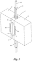
- Fig. 1 shows a connector 1 for two workpieces 2, 3.
- the workpieces 2, 3 are, for example, columns, pillars, main, side or cross member of a building, eg roof, or the like.
- the connector 1 is mainly for workpieces 2, 3 from Wood, for example wood beams made of solid wood, glued laminated timber (BSH), glued laminated wood ("glue binder”), etc.
- BSH glued laminated timber
- glue binder glued laminated wood
- One (or both) of the workpieces 2, 3 may also be made of a different material, such as concrete, masonry, etc., and Connector 1 can also be used, for example, to connect a wooden support 2 to a building part 3.
- the connector 1 is preferably made of metal, e.g. Steel and / or high-strength aluminum, but could be made of other materials such as wood or plastic at low load requirements.
- the connector 1 comprises two fittings 4, 5 which can be fastened with their one side 6, 7 to the respective workpiece 2, 3, as explained in more detail later. With their other sides 8, 9, the fittings 4, 5 can be brought into contact with each other.
- the plant pages 8, 9 can as shown plan or complementarily shaped to ensure a good mutual investment.
- Each clamping jaws 10, 11 has a keyway 12 for receiving the abutting, complementary wedge-shaped ends 14, 15 and 16, 17 of the fittings 4, 5.
- a threaded rod 18 which is received in mutually facing half-chamfers 19, 20 in the sides 8, 9 of the fittings 4, 5 and so passes through the abutting fittings 4, 5 approximately centrally.
- nuts 21, 22, which are mounted on the threaded rod 18 from the outside and press against the outside of the clamping jaws 10, 11, they can be clamped against each other.
- the clamping jaws 10, 11 could be provided with opposing internal threads 23, so that one or both nuts 21, 22 can be saved.
- the fittings 4, 5 - and optionally also the clamping jaws 10, 11 - are provided with holes 24 through which screws 25 can be passed and screwed into the workpieces 2, 3.
- each finger joint profile 26, 27 preferably run approximately normal to the / the threaded rod (s) 28, so that in the in the Fig. 1 and 2 shown exemplary installation position with vertical threaded rod 18, the finger joints 30 are approximately horizontal (see Fig. 2 ). This allows them to record vertical tension and pressure, ie vertical shear forces between the workpieces 2, 3, particularly well.
- the flank angles of the finger joints 30 of the finger splines 26, 27 are preferably also chosen to be flat so that they are self-locking.
- the sides 6, 7 or finger joint profiles 26, 27 can also be glued to the workpieces 2, 3 or their finger joint milling cuts 28, 29.
- FIGS. 5 and 6 show two different configurations of the finger joint profiles 26, 27.
- Fig. 6 are cylindrical segments of the fitting 4, 5 projecting finger joints 30 of the finger joint profiles 26, 27 shown.
- This embodiment is suitable for finger joint milling 28, 29, which are incorporated by means of circular disk milling in the workpieces 2, 3.
- each fitting 4, 5 can be designed not only in one piece, but also in several parts.
- the finger jointing profile 26, 27 may be formed in a separate adapter plate 31, which in the workpiece 2, 3 facing side 8, 9 of the respective fitting 4, 5 is used or mounted on this.
- the adapter plate 31 can be screwed, glued or otherwise connected to the remaining fitting ("fitting base body") 32, if desired also detachable or modular exchangeable. It also mutually complementary paragraphs, stages or the like. 33 or tongue and groove or dovetail joints 34 are provided for insertion, latching, latching, etc. between the adapter plate 31 and the base body 32.
- the adapter plate 31 can be connected by means of separate screws with the base body 32 or by means of the same screws 25, which fix the fitting 4, 5 on the workpiece 2, 3.
- the optional paragraphs 33 and 34 compounds for additional power transmission between adapter plate 31 and body 32 are used.
- fittings 4, 5 can be equipped with a finger joint profile 26, 27, e.g. if the other fitting 4, 5 for mounting on a concrete or steel beams, masonry od. Like. Without complementary finger joint milling is determined.
Description
Die vorliegende Erfindung betrifft einen Verbinder für zwei Werkstücke, mit zwei Beschlägen, die mit ihren einen Seiten an je einem der Werkstücke befestigbar und mit ihrer anderen Seiten aneinander zur Anlage bringbar sind, und zwei Spannbacken, welche die Beschläge an diametralen Enden ergreifen und mittels zumindest einer Gewindestange gegeneinander spannbar sind, die etwa parallel zu den genannten anderen Seiten verläuft.The present invention relates to a connector for two workpieces, with two fittings, which are fastened with their one side to each one of the workpieces and with their other sides abuttable to each other, and two clamping jaws which grip the fittings at diametral ends and by means of at least a threaded rod against each other are tensioned, which runs approximately parallel to said other sides.
Derartige Holzverbinder werden beispielsweise von der Firma Knapp GmbH, Euratsfeld, Österreich, unter der Marke Megant® vertrieben und eignen sich besonders zum Aufbau von Schwerlastverbindungen im Ingenieurholzbau, beispielsweise zum Verbinden von Haupt-, Neben- und/oder Querträgern, Querzügen, Bindern, Stützen od.dgl. Die Beschläge und Spannbacken sind dabei meist aus Metall, z.B. hochfestem Aluminium, und die zu verbindenden Werkstücke aus Holz, beispielsweise Brettschichtholz (BSH), Leimbindern usw. Eines der Werkstücke kann aber auch ein Betonträger, eine Mauer oder ein Boden sein, woran ein Träger mittels des Verbinders angeschlossen werden soll. Das Artikel "Stabil verbunden, aber leicht gelöst" (aus der
Dieses Ziel wird mit einem Verbinder der einleitend genannten Art erreicht, der sich gemäß der Erfindung dadurch auszeichnet, dass die genannte eine Seite zumindest eines Beschlags, bevorzugt beider Beschläge, mit einem Keilzinkenprofil versehen ist.This object is achieved with a connector of the aforementioned type, which according to the invention is characterized in that said one side of at least one fitting, preferably both fittings, is provided with a finger jointing profile.
Bei entsprechend komplementärer Keilzinkung des Werkstückes, an dem der Beschlag befestigt wird, kann damit eine hochfeste Keilzinkenverbindung zwischen Beschlag und Werkstück geschaffen werden, welche einen innigen, form- und kraftschlüssigen Anschluss des Verbinders an das Werkstück erzielt. Der Beschlag kann dabei optional auch mit dem Werkstück verklebt werden, um einen zusätzlichen Stoffschluss zwischen den beiden Teilen zu erreichen.In accordance with complementary complementary finger jointing of the workpiece to which the fitting is attached, so that a high-strength finger joint between fitting and workpiece can be created, which achieves an intimate, positive and non-positive connection of the connector to the workpiece. The fitting can optionally be glued to the workpiece, to achieve an additional bond between the two parts.
Aufgrund der Keilverzinkung des Beschlages mit dem Werkstück, beispielsweise einem BSH-Träger, kann gleichzeitig eine gute Abdichtung der Hirnholzfläche des Trägers erzielt werden, welche die Gefahr eines Eindringens von Feuchtigkeit in das Holz oder den Leim und damit ein Aufreißen der Leimfugen des BSH-Trägers beseitigt oder reduziert.Due to the Zeilverzinkung the fitting with the workpiece, such as a BSH carrier, at the same time a good seal the end grain of the wearer can be achieved, which increases the risk of moisture penetration into the wood or glue and thus tearing the glue joints of the BSH carrier eliminated or reduced.
Der erfindungsgemäße Verbinder eignet sich überdies besonders für Werkstücke aus schnellwachsenden Hölzern, die eine geringere Rohdichte und damit geringere Festigkeit haben und somit weniger Halt für Verschraubungen des Beschlages bieten. Durch die Keilverzinkung kann hier auf eine Erhöhung der Schraubenanzahl, welche sonst zur Kompensation der geringeren Rohdichte erforderlich wäre, verzichtet werden. Umgekehrt kann bei guten Holzqualitäten die Anzahl an Schrauben, die zur Befestigung der Beschläge erforderlich sind, reduziert und damit Gewicht und Kosten eingespart werden. Auch können aufwendige schräge Verschraubungen reduziert bzw. durch einfacher herzustellende gerade Verschraubungen ersetzt werden.The connector according to the invention is also particularly suitable for workpieces made of fast-growing woods, which have a lower bulk density and thus lower strength and thus provide less support for screwing the fitting. Through the Zeilverzinkung can be here on an increase in the number of screws, which would otherwise be required to compensate for the lower density, be dispensed with. Conversely, with good qualities of wood, the number of screws required to fasten the fittings can be reduced, thus saving weight and costs. Even costly oblique screwing can be reduced or replaced by simple to produce straight fittings.
Gemäß einer bevorzugten Ausführungsform der Erfindung verlaufen die Keilzinken des Keilzinkenprofils etwa normal zu der Gewindestange, so dass sie Zug- und Druckkräfte in Richtung der Gewindestange(n) gut aufnehmen bzw. abstützen können.According to a preferred embodiment of the invention, the finger joints of the finger joint profile run approximately normal to the threaded rod, so that they can absorb or support tensile and compressive forces in the direction of the threaded rod (s) well.
Bevorzugt werden - wie auf dem Gebiet von Keilzinkenverbindungen an sich bekannt - die Flankenwinkel der Keilzinken des Keilzinkenprofils selbsthemmend ausgeführt, um eine gute Kraftaufnahme zu gewährleisten.As is well known in the field of finger jointing, the flank angles of the finger joints of the finger joint profile are preferably self-locking in order to ensure a good absorption of force.
Eine besonders vorteilhafte Ausführungsform der Erfindung zeichnet sich dadurch aus, dass das Keilzinkenprofil in einer Adapterplatte ausgebildet ist, welche in die genannte eine Seite eines Beschlags eingesetzt oder auf dieser montiert ist. Der Verbinder der Erfindung kann dadurch modular aufgebaut, bevorratet und eingesetzt werden. Verschiedene Adapterplatten mit unterschiedlichen Keilzinkenprofilen können mit ein und demselben Beschlags-Grundkörper kombiniert werden, um eine Anpassung an verschiedene Werkstückmaterialien, z.B. Holzqualitäten, zu ermöglichen. So können Adapterplatten mit unterschiedlichen Keilzinkenprofilen in Hinblick auf Zinkenlänge, Zinkenteilung, Zinkenspiel, Flankenwinkel usw. je nach Werkstück und Anwendungszweck eingesetzt werden. Die Adapterplatte kann dabei mit dem restlichen Beschlag zusammengesteckt, verklinkt, verrastet, verklebt und/oder verschraubt werden.A particularly advantageous embodiment of the invention is characterized in that the finger jointing profile is formed in an adapter plate, which is inserted into said one side of a fitting or mounted thereon. The connector of the invention can thereby be modularly constructed, stored and used. Different adapter plates with different finger joint profiles can be with one and the same Fuse body can be combined to allow adaptation to different workpiece materials, such as wood qualities. Thus, adapter plates with different finger joint profiles in terms of tine length, zinc pitch, tine play, flank angle, etc., depending on the workpiece and application can be used. The adapter plate can be plugged together with the rest of fitting, latched, locked, glued and / or screwed.
Gemäß einer ersten Variante können die Spitzen der Keilzinken in einer Ebene vom Beschlag vorstehen, was eine einfache, gerade Fräsung der Keilzinkung in das anzuschließende Werkstück ermöglicht. Alternativ können die Spitzen der Keilzinken zylindersegmentartig vom Beschlag vorstehen, wodurch beispielsweise Scheibenfräser zur Herstellung der komplementären Keilzinkung im anzuschließenden Werkstück verwendet werden können.According to a first variant, the tips of the finger joints can protrude in a plane from the fitting, which allows a simple, straight milling of the finger joint in the workpiece to be connected. Alternatively, the tips of the finger joints can protrude like a cylinder segment from the fitting, whereby, for example, side milling cutters can be used to produce the complementary finger joint in the workpiece to be connected.
Neben der optionalen Möglichkeit einer Verklebung der Keilzinkenprofile der Beschläge mit den Werkstücken ist es günstig, wenn die Beschläge zusätzlich mit Bohrungen zur Verschraubung mit den Werkstücken versehen sind.In addition to the optional possibility of gluing the finger joint profiles of the fittings with the workpieces, it is advantageous if the fittings are additionally provided with holes for screwing to the workpieces.
In jedem Fall ist es besonders günstig, wenn - wie an sich z.B. von Megant®-Verbindern her bekannt - die genannten Enden der Beschläge keilförmig sind und jeder Spannbacken eine Keilnut zur Aufnahme zweier aneinander anliegender keilförmiger Enden aufweist. Die zumindest eine Gewindestange kann dabei in einander zugewandten Halbkehlen der genannten anderen Seiten der Beschläge aufgenommen sein. Dies ergibt einen rasch und hochfest zu schließenden Verbinder, bei welchem die Spannbacken über ihre Keilnuten die beiden Beschläge fest gegeneinander pressen.In any case, it is particularly favorable if, as per se, e.g. known from Megant® connectors - said ends of the fittings are wedge-shaped and each jaw has a keyway for receiving two abutting wedge-shaped ends. The at least one threaded rod can be accommodated in mutually facing half-indentations of said other sides of the fittings. This results in a fast and high-strength connector to be closed, in which the clamping jaws over their splines, the two fittings pressed firmly against each other.
Der Erfindung wird nachstehend anhand von in den beigeschlossenen Zeichnungen dargestellten Ausführungsbeispielen näher erläutert. In den Zeichnungen zeigen:
-
Fig. 1 einen Verbinder gemäß der Erfindung in der Montagestellung an zwei ausschnittsweise dargestellten Werkstücken in einer Perspektivansicht; -
Fig. 2 den Verbinder vonFig. 1 mitsamt Befestigungsschrauben in einer Perspektivansicht; -
Fig. 3 einen der Spannbacken des Verbinders vonFig. 1 in einer Perspektivansicht; -
Fig. 4 einen der Beschläge des Verbinders vonFig. 1 in Keilverzinkung mit einem ausschnittsweise dargestellten Werkstück; -
Fig. 5 eine alternative Ausführungsform eines der Beschläge des erfindungsgemäßen Verbinders in einer Perspektivansicht; und -
Fig. 6 eine weitere alternative Ausführungsform eines der Beschläge des erfindungsgemäßen Verbinders in einer Perspektivansicht.
-
Fig. 1 a connector according to the invention in the mounting position on two partial workpieces shown in a perspective view; -
Fig. 2 the connector ofFig. 1 together with fixing screws in a perspective view; -
Fig. 3 one of the jaws of the connector ofFig. 1 in a perspective view; -
Fig. 4 one of the fittings of the connector ofFig. 1 in finger-jointing with a partially illustrated workpiece; -
Fig. 5 an alternative embodiment of the fittings of the connector according to the invention in a perspective view; and -
Fig. 6 a further alternative embodiment of the fittings of the connector according to the invention in a perspective view.
Der Verbinder 1 ist bevorzugt aus Metall gefertigt, z.B. Stahl und/oder hochfestem Aluminium, könnte jedoch bei geringen Tragfestigkeitsanforderungen auch aus anderen Materialen wie Holz oder Kunststoff gefertigt sein.The
Gemäß
In der in den
Jeder Spannbacken 10, 11 hat eine Keilnut 12 zur Aufnahme der aneinander anliegenden, dazu komplementär keilförmig ausgestalteten Enden 14, 15 bzw. 16, 17 der Beschläge 4, 5. Durch Gegeneinanderspannen der Spannbacken 10, 11 werden somit die Beschläge 4, 5 mit ihren Seiten 8, 9 aneinander angepresst.Each
Zum Gegeneinanderspannen der Spannbacken 10, 11 dient eine Gewindestange 18, welche in einander zugewandten Halbkehlen 19, 20 in den Seiten 8, 9 der Beschläge 4, 5 aufgenommen ist und so die aneinander anliegenden Beschläge 4, 5 etwa mittig durchsetzt. Mit Hilfe von Muttern 21, 22, welche von außen auf die Gewindestange 18 aufgezogen sind und gegen die Außenseite der Spannbacken 10, 11 pressen, können diese gegeneinander gespannt werden. Alternativ könnten die Spannbacken 10, 11 auch mit gegenläufigen Innengewinden 23 versehen sein, so dass eine oder beide Muttern 21, 22 eingespart werden können.For mutual clamping of the
Es versteht sich, dass anstelle einer einzigen Gewindestange 18 auch zwei oder mehr Gewindestangen je nach Lasterfordernissen verwendet werden können. Auch jede andere Art von Spanneinrichtung für das Gegeneinanderspannen der Spannbacken 10, 11 ist möglich, beispielsweise daran außenseitig angreifende Schraubzwingen od.dgl.It is understood that instead of a single threaded
Die Beschläge 4, 5 - und optional auch die Spannbacken 10, 11 - sind mit Bohrungen 24 versehen, durch welche Schrauben 25 hindurchgeführt und in die Werkstücke 2, 3 eingeschraubt werden können.The
Zum innigen Verbund der Beschläge 4, 5 mit den Werkstücken 2, 3 ist die dem jeweiligen Werkstück zugewandte Seite 6, 7 eines Beschlags 4, 5 mit einem Keilzinkenprofil 26, 27 ausgestattet, das eine Keilzinkenverbindung mit einer entsprechend komplementären Keilzinkenfräsung 28, 29 im jeweiligen Werkstück 2, 3 eingehen kann. Die Keilzinken 30 jedes Keilzinkenprofils 26, 27 verlaufen dabei bevorzugt etwa normal zu der/den Gewindestange(n) 28, so dass in der in den
Optional können die Seiten 6, 7 bzw. Keilzinkenprofile 26, 27 auch mit den Werkstücken 2, 3 bzw. deren Keilzinkenfräsungen 28, 29 verklebt werden.Optionally, the
Die
Gemäß
Die Adapterplatte 31 kann mit dem restlichen Beschlag ("Beschlags-Grundkörper") 32 verschraubt, verklebt oder sonstwie verbunden werden, falls gewünscht auch lösbar bzw. modular austauschbar. Dabei können auch zueinander komplementäre Absätze, Stufen od.dgl. 33 oder Nut-/Feder- oder Schwalbenschwanzverbindungen 34 für ein Einschieben, Verrasten, Verklinken usw. zwischen der Adapterplatte 31 und dem Grundkörper 32 vorgesehen werden.The
Die Adapterplatte 31 kann mittels gesonderter Schrauben mit dem Grundkörper 32 verbunden werden oder mittels derselben Schrauben 25, welche den Beschlag 4, 5 am Werkstück 2, 3 fixieren. Dabei dienen die optionalen Absätze 33 bzw. Verbindungen 34 zur zusätzlichen Kraftübertragung zwischen Adapterplatte 31 und Grundkörper 32.The
Es versteht sich, dass in einfachen Ausführungsformen auch lediglich nur einer der Beschläge 4, 5 mit einem Keilzinkenprofil 26, 27 ausgestattet sein kann, z.B. wenn der andere Beschlag 4, 5 zur Montage an einem Beton- oder Stahlträger, Mauerwerk od. dgl. ohne komplementäre Keilzinkenfräsung bestimmt ist.It is understood that in simple embodiments, only one of the
Die Erfindung ist demgemäß nicht auf die dargestellten Ausführungsformen beschränkt, sondern umfasst alle Varianten, Modifikationen und Kombinationen, die in den Rahmen der angeschlossenen Ansprüche fallen.The invention is therefore not limited to the illustrated embodiments, but includes all variants, modifications, and combinations that fall within the scope of the appended claims.
Claims (10)
- Connector (1) for two work pieces (2, 3), comprising two fittings (4, 5) which each can be attached with one of their sides (6, 7) to one of the work pieces (2, 3) and which can be brought with their respective other sides (8, 9) into abutment against each other, and
two clamping jaws (10, 11) which engage the fittings (4, 5) at diametral ends (14, 15; 16, 17) and which can be clamped against each other by means of at least one threaded bar (18) that runs substantially parallel to said other sides (8, 9), characterised in that
said one side (6, 7) of at least one fitting (4, 5), preferably of both fittings (4, 5), is provided with a wedged-keys profile (26, 27). - Connector according to claim 1, characterised in that the wedged keys (30) of the wedged-keys profile (26, 27) run substantially normally to the threaded bar (18).
- Connector according to claim 1 or 2, characterised in that the flank angle of the wedged keys (30) of the wedged-keys profile (26, 27) are self-locking.
- Connector according to any one of the claims 1 to 3, characterised in that the wedged-keys profile (26, 27) is formed in an adaptor plate (31) that is inserted into said one side (6, 7) of one fitting (4, 5) or mounted on said one side (6, 7).
- Connector according to claim 4, characterised in that the adaptor plate (31) can be screwed together with the remainder of the fitting (32).
- Connector according to any one of the claims 1 to 5, characterised in that the tips of the wedged keys (30) produde from the fitting (4, 5) in a plane.
- Connector according to any one of the claims 1 to 5, characterised in that the tips of the wedged keys (30) produde from the fitting (4, 5) in form of a cylinder segment.
- Connector according to any one of the claims 1 to 7, characterised in that the fittings (4, 5) are provided with bores (24) for screw-fastening with the work pieces (2, 3).
- Connector according to any one of the claims 1 to 8, characterised in that said ends (14 - 17) of the fittings (4, 5) are wedge-shaped and each clamping jaw (10, 11) has a tapered groove (12) for receiving two wedge-shaped ends (14, 15; 16, 17) that abut against each other.
- Connector according to any one of the claims 1 to 9, characterised in that said at least one threaded bar (18) is received in mutually facing grooves (29) of said other sides (8, 9).
Priority Applications (2)
| Application Number | Priority Date | Filing Date | Title |
|---|---|---|---|
| EP15186790.0A EP3147419B1 (en) | 2015-09-25 | 2015-09-25 | Connector |
| PCT/EP2016/071643 WO2017050615A1 (en) | 2015-09-25 | 2016-09-14 | Connector |
Applications Claiming Priority (1)
| Application Number | Priority Date | Filing Date | Title |
|---|---|---|---|
| EP15186790.0A EP3147419B1 (en) | 2015-09-25 | 2015-09-25 | Connector |
Publications (2)
| Publication Number | Publication Date |
|---|---|
| EP3147419A1 EP3147419A1 (en) | 2017-03-29 |
| EP3147419B1 true EP3147419B1 (en) | 2018-04-11 |
Family
ID=54207332
Family Applications (1)
| Application Number | Title | Priority Date | Filing Date |
|---|---|---|---|
| EP15186790.0A Active EP3147419B1 (en) | 2015-09-25 | 2015-09-25 | Connector |
Country Status (2)
| Country | Link |
|---|---|
| EP (1) | EP3147419B1 (en) |
| WO (1) | WO2017050615A1 (en) |
Families Citing this family (2)
| Publication number | Priority date | Publication date | Assignee | Title |
|---|---|---|---|---|
| EP3348722B1 (en) * | 2017-01-13 | 2020-04-01 | Knapp GmbH | Connector and device for coupling vertical components |
| EP4350094A1 (en) * | 2022-10-07 | 2024-04-10 | Rotho Blaas GmbH/Srl | Connection system for connecting building elements to at least one wooden building element |
Family Cites Families (3)
| Publication number | Priority date | Publication date | Assignee | Title |
|---|---|---|---|---|
| DE102005014900A1 (en) * | 2005-04-01 | 2006-10-05 | Induo Gesellschaft Zur Verwertung Von Schutzrechten Mbh & Co Kg | Composite anchor for connecting at least two components and system of interconnected components |
| DE102008010612A1 (en) * | 2008-02-22 | 2009-09-03 | Kratzer, Daniel | connecting body |
| DE202013100120U1 (en) * | 2013-01-10 | 2014-04-11 | SCHÜCO International KG | T-joint for a mullion and transom construction |
-
2015
- 2015-09-25 EP EP15186790.0A patent/EP3147419B1/en active Active
-
2016
- 2016-09-14 WO PCT/EP2016/071643 patent/WO2017050615A1/en active Application Filing
Non-Patent Citations (1)
| Title |
|---|
| None * |
Also Published As
| Publication number | Publication date |
|---|---|
| EP3147419A1 (en) | 2017-03-29 |
| WO2017050615A1 (en) | 2017-03-30 |
Similar Documents
| Publication | Publication Date | Title |
|---|---|---|
| EP1007809B1 (en) | Reinforcement device for supporting structures | |
| EP3456892B1 (en) | Connector for two workpieces | |
| EP3366855B1 (en) | Connector, support and device for coupling vertical components | |
| AT5013U1 (en) | MOUNTING DEVICE FOR SETTING FASTENERS WHEN JOINING OVERLAPED BEAMS AT THEIR END | |
| EP1729018B1 (en) | Extrusion connection system | |
| DE102008029935B3 (en) | Connection device for e.g. plates, has support elements arranged in tapering device, in which free space arranged between connection projections and opposite ends of receiving recesses with connection parts that are connected together | |
| EP3433440A1 (en) | Method and connector set for connecting beams of wood material | |
| DE102010035330B4 (en) | Device for fastening a drill stand for a drilling machine | |
| EP3147419B1 (en) | Connector | |
| DE10359761A1 (en) | clamping device | |
| DE102015002272B4 (en) | Hollow profile connection for extending or right-angled connection of rectangular cross-sections with hollow profiles | |
| EP1699986B1 (en) | Wood wall construction made of wooden beams | |
| CH702591A2 (en) | Mounting device for assembling lockable pipe clamp into e.g. wall, has clamp screw coaxially aligned to spindle that is connectable with drill press and connected on rear side of base body whose front surface runs along receiving opening | |
| EP1602836B1 (en) | Stiffening ridge for solid wood | |
| DE202011003315U1 (en) | connecting device | |
| AT506192B1 (en) | CONNECTOR | |
| DE202014005734U1 (en) | Tape hub | |
| DE10027572C2 (en) | Spring clamps | |
| EP2604868B1 (en) | Method and device for connecting components | |
| DE3506455C2 (en) | ||
| CH698907A2 (en) | Obscured fastener for components. | |
| EP1605172B1 (en) | Fitting for connecting an elongate structural member and a flat structural member | |
| DE602006001035T2 (en) | Fixing system for profiles | |
| DE202005009746U1 (en) | Clamping mechanism for e.g. chuck, of e.g. machine tool, has clamping units fixable together by thrust bearing in fixed position in friction-fit manner and including sectional contact surfaces, which form frictional end in fixed condition | |
| AT12448U1 (en) | CONNECTION DEVICE |
Legal Events
| Date | Code | Title | Description |
|---|---|---|---|
| PUAI | Public reference made under article 153(3) epc to a published international application that has entered the european phase |
Free format text: ORIGINAL CODE: 0009012 |
|
| AK | Designated contracting states |
Kind code of ref document: A1 Designated state(s): AL AT BE BG CH CY CZ DE DK EE ES FI FR GB GR HR HU IE IS IT LI LT LU LV MC MK MT NL NO PL PT RO RS SE SI SK SM TR |
|
| AX | Request for extension of the european patent |
Extension state: BA ME |
|
| 17P | Request for examination filed |
Effective date: 20170928 |
|
| RBV | Designated contracting states (corrected) |
Designated state(s): AL AT BE BG CH CY CZ DE DK EE ES FI FR GB GR HR HU IE IS IT LI LT LU LV MC MK MT NL NO PL PT RO RS SE SI SK SM TR |
|
| GRAP | Despatch of communication of intention to grant a patent |
Free format text: ORIGINAL CODE: EPIDOSNIGR1 |
|
| INTG | Intention to grant announced |
Effective date: 20171110 |
|
| GRAS | Grant fee paid |
Free format text: ORIGINAL CODE: EPIDOSNIGR3 |
|
| GRAA | (expected) grant |
Free format text: ORIGINAL CODE: 0009210 |
|
| AK | Designated contracting states |
Kind code of ref document: B1 Designated state(s): AL AT BE BG CH CY CZ DE DK EE ES FI FR GB GR HR HU IE IS IT LI LT LU LV MC MK MT NL NO PL PT RO RS SE SI SK SM TR |
|
| REG | Reference to a national code |
Ref country code: GB Ref legal event code: FG4D Free format text: NOT ENGLISH |
|
| REG | Reference to a national code |
Ref country code: CH Ref legal event code: EP |
|
| REG | Reference to a national code |
Ref country code: AT Ref legal event code: REF Ref document number: 988176 Country of ref document: AT Kind code of ref document: T Effective date: 20180415 |
|
| REG | Reference to a national code |
Ref country code: CH Ref legal event code: NV Representative=s name: HEPP WENGER RYFFEL AG, CH |
|
| REG | Reference to a national code |
Ref country code: IE Ref legal event code: FG4D Free format text: LANGUAGE OF EP DOCUMENT: GERMAN |
|
| REG | Reference to a national code |
Ref country code: DE Ref legal event code: R096 Ref document number: 502015003804 Country of ref document: DE |
|
| REG | Reference to a national code |
Ref country code: NL Ref legal event code: MP Effective date: 20180411 |
|
| REG | Reference to a national code |
Ref country code: LT Ref legal event code: MG4D |
|
| REG | Reference to a national code |
Ref country code: FR Ref legal event code: PLFP Year of fee payment: 4 |
|
| PG25 | Lapsed in a contracting state [announced via postgrant information from national office to epo] |
Ref country code: NL Free format text: LAPSE BECAUSE OF FAILURE TO SUBMIT A TRANSLATION OF THE DESCRIPTION OR TO PAY THE FEE WITHIN THE PRESCRIBED TIME-LIMIT Effective date: 20180411 |
|
| PG25 | Lapsed in a contracting state [announced via postgrant information from national office to epo] |
Ref country code: SE Free format text: LAPSE BECAUSE OF FAILURE TO SUBMIT A TRANSLATION OF THE DESCRIPTION OR TO PAY THE FEE WITHIN THE PRESCRIBED TIME-LIMIT Effective date: 20180411 Ref country code: ES Free format text: LAPSE BECAUSE OF FAILURE TO SUBMIT A TRANSLATION OF THE DESCRIPTION OR TO PAY THE FEE WITHIN THE PRESCRIBED TIME-LIMIT Effective date: 20180411 Ref country code: AL Free format text: LAPSE BECAUSE OF FAILURE TO SUBMIT A TRANSLATION OF THE DESCRIPTION OR TO PAY THE FEE WITHIN THE PRESCRIBED TIME-LIMIT Effective date: 20180411 Ref country code: BG Free format text: LAPSE BECAUSE OF FAILURE TO SUBMIT A TRANSLATION OF THE DESCRIPTION OR TO PAY THE FEE WITHIN THE PRESCRIBED TIME-LIMIT Effective date: 20180711 Ref country code: FI Free format text: LAPSE BECAUSE OF FAILURE TO SUBMIT A TRANSLATION OF THE DESCRIPTION OR TO PAY THE FEE WITHIN THE PRESCRIBED TIME-LIMIT Effective date: 20180411 Ref country code: NO Free format text: LAPSE BECAUSE OF FAILURE TO SUBMIT A TRANSLATION OF THE DESCRIPTION OR TO PAY THE FEE WITHIN THE PRESCRIBED TIME-LIMIT Effective date: 20180711 Ref country code: LT Free format text: LAPSE BECAUSE OF FAILURE TO SUBMIT A TRANSLATION OF THE DESCRIPTION OR TO PAY THE FEE WITHIN THE PRESCRIBED TIME-LIMIT Effective date: 20180411 Ref country code: PL Free format text: LAPSE BECAUSE OF FAILURE TO SUBMIT A TRANSLATION OF THE DESCRIPTION OR TO PAY THE FEE WITHIN THE PRESCRIBED TIME-LIMIT Effective date: 20180411 |
|
| PG25 | Lapsed in a contracting state [announced via postgrant information from national office to epo] |
Ref country code: GR Free format text: LAPSE BECAUSE OF FAILURE TO SUBMIT A TRANSLATION OF THE DESCRIPTION OR TO PAY THE FEE WITHIN THE PRESCRIBED TIME-LIMIT Effective date: 20180712 Ref country code: HR Free format text: LAPSE BECAUSE OF FAILURE TO SUBMIT A TRANSLATION OF THE DESCRIPTION OR TO PAY THE FEE WITHIN THE PRESCRIBED TIME-LIMIT Effective date: 20180411 Ref country code: RS Free format text: LAPSE BECAUSE OF FAILURE TO SUBMIT A TRANSLATION OF THE DESCRIPTION OR TO PAY THE FEE WITHIN THE PRESCRIBED TIME-LIMIT Effective date: 20180411 Ref country code: LV Free format text: LAPSE BECAUSE OF FAILURE TO SUBMIT A TRANSLATION OF THE DESCRIPTION OR TO PAY THE FEE WITHIN THE PRESCRIBED TIME-LIMIT Effective date: 20180411 |
|
| PG25 | Lapsed in a contracting state [announced via postgrant information from national office to epo] |
Ref country code: PT Free format text: LAPSE BECAUSE OF FAILURE TO SUBMIT A TRANSLATION OF THE DESCRIPTION OR TO PAY THE FEE WITHIN THE PRESCRIBED TIME-LIMIT Effective date: 20180813 |
|
| REG | Reference to a national code |
Ref country code: DE Ref legal event code: R097 Ref document number: 502015003804 Country of ref document: DE |
|
| PG25 | Lapsed in a contracting state [announced via postgrant information from national office to epo] |
Ref country code: RO Free format text: LAPSE BECAUSE OF FAILURE TO SUBMIT A TRANSLATION OF THE DESCRIPTION OR TO PAY THE FEE WITHIN THE PRESCRIBED TIME-LIMIT Effective date: 20180411 Ref country code: CZ Free format text: LAPSE BECAUSE OF FAILURE TO SUBMIT A TRANSLATION OF THE DESCRIPTION OR TO PAY THE FEE WITHIN THE PRESCRIBED TIME-LIMIT Effective date: 20180411 Ref country code: EE Free format text: LAPSE BECAUSE OF FAILURE TO SUBMIT A TRANSLATION OF THE DESCRIPTION OR TO PAY THE FEE WITHIN THE PRESCRIBED TIME-LIMIT Effective date: 20180411 Ref country code: DK Free format text: LAPSE BECAUSE OF FAILURE TO SUBMIT A TRANSLATION OF THE DESCRIPTION OR TO PAY THE FEE WITHIN THE PRESCRIBED TIME-LIMIT Effective date: 20180411 Ref country code: SK Free format text: LAPSE BECAUSE OF FAILURE TO SUBMIT A TRANSLATION OF THE DESCRIPTION OR TO PAY THE FEE WITHIN THE PRESCRIBED TIME-LIMIT Effective date: 20180411 |
|
| PLBE | No opposition filed within time limit |
Free format text: ORIGINAL CODE: 0009261 |
|
| STAA | Information on the status of an ep patent application or granted ep patent |
Free format text: STATUS: NO OPPOSITION FILED WITHIN TIME LIMIT |
|
| PG25 | Lapsed in a contracting state [announced via postgrant information from national office to epo] |
Ref country code: IT Free format text: LAPSE BECAUSE OF FAILURE TO SUBMIT A TRANSLATION OF THE DESCRIPTION OR TO PAY THE FEE WITHIN THE PRESCRIBED TIME-LIMIT Effective date: 20180411 Ref country code: SM Free format text: LAPSE BECAUSE OF FAILURE TO SUBMIT A TRANSLATION OF THE DESCRIPTION OR TO PAY THE FEE WITHIN THE PRESCRIBED TIME-LIMIT Effective date: 20180411 |
|
| 26N | No opposition filed |
Effective date: 20190114 |
|
| PG25 | Lapsed in a contracting state [announced via postgrant information from national office to epo] |
Ref country code: MC Free format text: LAPSE BECAUSE OF FAILURE TO SUBMIT A TRANSLATION OF THE DESCRIPTION OR TO PAY THE FEE WITHIN THE PRESCRIBED TIME-LIMIT Effective date: 20180411 |
|
| PG25 | Lapsed in a contracting state [announced via postgrant information from national office to epo] |
Ref country code: SI Free format text: LAPSE BECAUSE OF FAILURE TO SUBMIT A TRANSLATION OF THE DESCRIPTION OR TO PAY THE FEE WITHIN THE PRESCRIBED TIME-LIMIT Effective date: 20180411 |
|
| REG | Reference to a national code |
Ref country code: BE Ref legal event code: MM Effective date: 20180930 |
|
| REG | Reference to a national code |
Ref country code: IE Ref legal event code: MM4A |
|
| PG25 | Lapsed in a contracting state [announced via postgrant information from national office to epo] |
Ref country code: LU Free format text: LAPSE BECAUSE OF NON-PAYMENT OF DUE FEES Effective date: 20180925 |
|
| PG25 | Lapsed in a contracting state [announced via postgrant information from national office to epo] |
Ref country code: IE Free format text: LAPSE BECAUSE OF NON-PAYMENT OF DUE FEES Effective date: 20180925 |
|
| PG25 | Lapsed in a contracting state [announced via postgrant information from national office to epo] |
Ref country code: BE Free format text: LAPSE BECAUSE OF NON-PAYMENT OF DUE FEES Effective date: 20180930 |
|
| PG25 | Lapsed in a contracting state [announced via postgrant information from national office to epo] |
Ref country code: MT Free format text: LAPSE BECAUSE OF FAILURE TO SUBMIT A TRANSLATION OF THE DESCRIPTION OR TO PAY THE FEE WITHIN THE PRESCRIBED TIME-LIMIT Effective date: 20180411 |
|
| PG25 | Lapsed in a contracting state [announced via postgrant information from national office to epo] |
Ref country code: TR Free format text: LAPSE BECAUSE OF FAILURE TO SUBMIT A TRANSLATION OF THE DESCRIPTION OR TO PAY THE FEE WITHIN THE PRESCRIBED TIME-LIMIT Effective date: 20180411 |
|
| PG25 | Lapsed in a contracting state [announced via postgrant information from national office to epo] |
Ref country code: CY Free format text: LAPSE BECAUSE OF FAILURE TO SUBMIT A TRANSLATION OF THE DESCRIPTION OR TO PAY THE FEE WITHIN THE PRESCRIBED TIME-LIMIT Effective date: 20180411 Ref country code: MK Free format text: LAPSE BECAUSE OF NON-PAYMENT OF DUE FEES Effective date: 20180411 Ref country code: HU Free format text: LAPSE BECAUSE OF FAILURE TO SUBMIT A TRANSLATION OF THE DESCRIPTION OR TO PAY THE FEE WITHIN THE PRESCRIBED TIME-LIMIT; INVALID AB INITIO Effective date: 20150925 |
|
| PG25 | Lapsed in a contracting state [announced via postgrant information from national office to epo] |
Ref country code: IS Free format text: LAPSE BECAUSE OF FAILURE TO SUBMIT A TRANSLATION OF THE DESCRIPTION OR TO PAY THE FEE WITHIN THE PRESCRIBED TIME-LIMIT Effective date: 20180811 |
|
| PGFP | Annual fee paid to national office [announced via postgrant information from national office to epo] |
Ref country code: AT Payment date: 20230929 Year of fee payment: 9 |
|
| PGFP | Annual fee paid to national office [announced via postgrant information from national office to epo] |
Ref country code: FR Payment date: 20230914 Year of fee payment: 9 Ref country code: DE Payment date: 20230929 Year of fee payment: 9 |
|
| PGFP | Annual fee paid to national office [announced via postgrant information from national office to epo] |
Ref country code: GB Payment date: 20231002 Year of fee payment: 9 |
|
| PGFP | Annual fee paid to national office [announced via postgrant information from national office to epo] |
Ref country code: CH Payment date: 20231004 Year of fee payment: 9 |