EP3147166B1 - Fahrzeugsteuerungsvorrichtung - Google Patents
Fahrzeugsteuerungsvorrichtung Download PDFInfo
- Publication number
- EP3147166B1 EP3147166B1 EP15795457.9A EP15795457A EP3147166B1 EP 3147166 B1 EP3147166 B1 EP 3147166B1 EP 15795457 A EP15795457 A EP 15795457A EP 3147166 B1 EP3147166 B1 EP 3147166B1
- Authority
- EP
- European Patent Office
- Prior art keywords
- wheel speed
- vehicle
- wheels
- control
- speed
- Prior art date
- Legal status (The legal status is an assumption and is not a legal conclusion. Google has not performed a legal analysis and makes no representation as to the accuracy of the status listed.)
- Active
Links
Images





Classifications
-
- B—PERFORMING OPERATIONS; TRANSPORTING
- B60—VEHICLES IN GENERAL
- B60T—VEHICLE BRAKE CONTROL SYSTEMS OR PARTS THEREOF; BRAKE CONTROL SYSTEMS OR PARTS THEREOF, IN GENERAL; ARRANGEMENT OF BRAKING ELEMENTS ON VEHICLES IN GENERAL; PORTABLE DEVICES FOR PREVENTING UNWANTED MOVEMENT OF VEHICLES; VEHICLE MODIFICATIONS TO FACILITATE COOLING OF BRAKES
- B60T8/00—Arrangements for adjusting wheel-braking force to meet varying vehicular or ground-surface conditions, e.g. limiting or varying distribution of braking force
- B60T8/17—Using electrical or electronic regulation means to control braking
- B60T8/1755—Brake regulation specially adapted to control the stability of the vehicle, e.g. taking into account yaw rate or transverse acceleration in a curve
-
- B—PERFORMING OPERATIONS; TRANSPORTING
- B60—VEHICLES IN GENERAL
- B60T—VEHICLE BRAKE CONTROL SYSTEMS OR PARTS THEREOF; BRAKE CONTROL SYSTEMS OR PARTS THEREOF, IN GENERAL; ARRANGEMENT OF BRAKING ELEMENTS ON VEHICLES IN GENERAL; PORTABLE DEVICES FOR PREVENTING UNWANTED MOVEMENT OF VEHICLES; VEHICLE MODIFICATIONS TO FACILITATE COOLING OF BRAKES
- B60T8/00—Arrangements for adjusting wheel-braking force to meet varying vehicular or ground-surface conditions, e.g. limiting or varying distribution of braking force
- B60T8/17—Using electrical or electronic regulation means to control braking
- B60T8/1755—Brake regulation specially adapted to control the stability of the vehicle, e.g. taking into account yaw rate or transverse acceleration in a curve
- B60T8/17551—Brake regulation specially adapted to control the stability of the vehicle, e.g. taking into account yaw rate or transverse acceleration in a curve determining control parameters related to vehicle stability used in the regulation, e.g. by calculations involving measured or detected parameters
-
- B—PERFORMING OPERATIONS; TRANSPORTING
- B60—VEHICLES IN GENERAL
- B60T—VEHICLE BRAKE CONTROL SYSTEMS OR PARTS THEREOF; BRAKE CONTROL SYSTEMS OR PARTS THEREOF, IN GENERAL; ARRANGEMENT OF BRAKING ELEMENTS ON VEHICLES IN GENERAL; PORTABLE DEVICES FOR PREVENTING UNWANTED MOVEMENT OF VEHICLES; VEHICLE MODIFICATIONS TO FACILITATE COOLING OF BRAKES
- B60T8/00—Arrangements for adjusting wheel-braking force to meet varying vehicular or ground-surface conditions, e.g. limiting or varying distribution of braking force
- B60T8/17—Using electrical or electronic regulation means to control braking
- B60T8/171—Detecting parameters used in the regulation; Measuring values used in the regulation
-
- B—PERFORMING OPERATIONS; TRANSPORTING
- B60—VEHICLES IN GENERAL
- B60T—VEHICLE BRAKE CONTROL SYSTEMS OR PARTS THEREOF; BRAKE CONTROL SYSTEMS OR PARTS THEREOF, IN GENERAL; ARRANGEMENT OF BRAKING ELEMENTS ON VEHICLES IN GENERAL; PORTABLE DEVICES FOR PREVENTING UNWANTED MOVEMENT OF VEHICLES; VEHICLE MODIFICATIONS TO FACILITATE COOLING OF BRAKES
- B60T8/00—Arrangements for adjusting wheel-braking force to meet varying vehicular or ground-surface conditions, e.g. limiting or varying distribution of braking force
- B60T8/17—Using electrical or electronic regulation means to control braking
- B60T8/175—Brake regulation specially adapted to prevent excessive wheel spin during vehicle acceleration, e.g. for traction control
-
- B—PERFORMING OPERATIONS; TRANSPORTING
- B60—VEHICLES IN GENERAL
- B60T—VEHICLE BRAKE CONTROL SYSTEMS OR PARTS THEREOF; BRAKE CONTROL SYSTEMS OR PARTS THEREOF, IN GENERAL; ARRANGEMENT OF BRAKING ELEMENTS ON VEHICLES IN GENERAL; PORTABLE DEVICES FOR PREVENTING UNWANTED MOVEMENT OF VEHICLES; VEHICLE MODIFICATIONS TO FACILITATE COOLING OF BRAKES
- B60T8/00—Arrangements for adjusting wheel-braking force to meet varying vehicular or ground-surface conditions, e.g. limiting or varying distribution of braking force
- B60T8/17—Using electrical or electronic regulation means to control braking
- B60T8/1755—Brake regulation specially adapted to control the stability of the vehicle, e.g. taking into account yaw rate or transverse acceleration in a curve
- B60T8/17552—Brake regulation specially adapted to control the stability of the vehicle, e.g. taking into account yaw rate or transverse acceleration in a curve responsive to the tyre sideslip angle or the vehicle body slip angle
-
- B—PERFORMING OPERATIONS; TRANSPORTING
- B60—VEHICLES IN GENERAL
- B60T—VEHICLE BRAKE CONTROL SYSTEMS OR PARTS THEREOF; BRAKE CONTROL SYSTEMS OR PARTS THEREOF, IN GENERAL; ARRANGEMENT OF BRAKING ELEMENTS ON VEHICLES IN GENERAL; PORTABLE DEVICES FOR PREVENTING UNWANTED MOVEMENT OF VEHICLES; VEHICLE MODIFICATIONS TO FACILITATE COOLING OF BRAKES
- B60T8/00—Arrangements for adjusting wheel-braking force to meet varying vehicular or ground-surface conditions, e.g. limiting or varying distribution of braking force
- B60T8/32—Arrangements for adjusting wheel-braking force to meet varying vehicular or ground-surface conditions, e.g. limiting or varying distribution of braking force responsive to a speed condition, e.g. acceleration or deceleration
- B60T8/3205—Arrangements for adjusting wheel-braking force to meet varying vehicular or ground-surface conditions, e.g. limiting or varying distribution of braking force responsive to a speed condition, e.g. acceleration or deceleration acceleration
-
- B—PERFORMING OPERATIONS; TRANSPORTING
- B60—VEHICLES IN GENERAL
- B60T—VEHICLE BRAKE CONTROL SYSTEMS OR PARTS THEREOF; BRAKE CONTROL SYSTEMS OR PARTS THEREOF, IN GENERAL; ARRANGEMENT OF BRAKING ELEMENTS ON VEHICLES IN GENERAL; PORTABLE DEVICES FOR PREVENTING UNWANTED MOVEMENT OF VEHICLES; VEHICLE MODIFICATIONS TO FACILITATE COOLING OF BRAKES
- B60T8/00—Arrangements for adjusting wheel-braking force to meet varying vehicular or ground-surface conditions, e.g. limiting or varying distribution of braking force
- B60T8/32—Arrangements for adjusting wheel-braking force to meet varying vehicular or ground-surface conditions, e.g. limiting or varying distribution of braking force responsive to a speed condition, e.g. acceleration or deceleration
- B60T8/34—Arrangements for adjusting wheel-braking force to meet varying vehicular or ground-surface conditions, e.g. limiting or varying distribution of braking force responsive to a speed condition, e.g. acceleration or deceleration having a fluid pressure regulator responsive to a speed condition
- B60T8/48—Arrangements for adjusting wheel-braking force to meet varying vehicular or ground-surface conditions, e.g. limiting or varying distribution of braking force responsive to a speed condition, e.g. acceleration or deceleration having a fluid pressure regulator responsive to a speed condition connecting the brake actuator to an alternative or additional source of fluid pressure, e.g. traction control systems
- B60T8/4809—Traction control, stability control, using both the wheel brakes and other automatic braking systems
- B60T8/4827—Traction control, stability control, using both the wheel brakes and other automatic braking systems in hydraulic brake systems
-
- B—PERFORMING OPERATIONS; TRANSPORTING
- B60—VEHICLES IN GENERAL
- B60T—VEHICLE BRAKE CONTROL SYSTEMS OR PARTS THEREOF; BRAKE CONTROL SYSTEMS OR PARTS THEREOF, IN GENERAL; ARRANGEMENT OF BRAKING ELEMENTS ON VEHICLES IN GENERAL; PORTABLE DEVICES FOR PREVENTING UNWANTED MOVEMENT OF VEHICLES; VEHICLE MODIFICATIONS TO FACILITATE COOLING OF BRAKES
- B60T2220/00—Monitoring, detecting driver behaviour; Signalling thereof; Counteracting thereof
- B60T2220/04—Pedal travel sensor, stroke sensor; Sensing brake request
-
- B—PERFORMING OPERATIONS; TRANSPORTING
- B60—VEHICLES IN GENERAL
- B60T—VEHICLE BRAKE CONTROL SYSTEMS OR PARTS THEREOF; BRAKE CONTROL SYSTEMS OR PARTS THEREOF, IN GENERAL; ARRANGEMENT OF BRAKING ELEMENTS ON VEHICLES IN GENERAL; PORTABLE DEVICES FOR PREVENTING UNWANTED MOVEMENT OF VEHICLES; VEHICLE MODIFICATIONS TO FACILITATE COOLING OF BRAKES
- B60T2230/00—Monitoring, detecting special vehicle behaviour; Counteracting thereof
- B60T2230/02—Side slip angle, attitude angle, floating angle, drift angle
-
- B—PERFORMING OPERATIONS; TRANSPORTING
- B60—VEHICLES IN GENERAL
- B60T—VEHICLE BRAKE CONTROL SYSTEMS OR PARTS THEREOF; BRAKE CONTROL SYSTEMS OR PARTS THEREOF, IN GENERAL; ARRANGEMENT OF BRAKING ELEMENTS ON VEHICLES IN GENERAL; PORTABLE DEVICES FOR PREVENTING UNWANTED MOVEMENT OF VEHICLES; VEHICLE MODIFICATIONS TO FACILITATE COOLING OF BRAKES
- B60T2250/00—Monitoring, detecting, estimating vehicle conditions
- B60T2250/03—Vehicle yaw rate
-
- B—PERFORMING OPERATIONS; TRANSPORTING
- B60—VEHICLES IN GENERAL
- B60T—VEHICLE BRAKE CONTROL SYSTEMS OR PARTS THEREOF; BRAKE CONTROL SYSTEMS OR PARTS THEREOF, IN GENERAL; ARRANGEMENT OF BRAKING ELEMENTS ON VEHICLES IN GENERAL; PORTABLE DEVICES FOR PREVENTING UNWANTED MOVEMENT OF VEHICLES; VEHICLE MODIFICATIONS TO FACILITATE COOLING OF BRAKES
- B60T2250/00—Monitoring, detecting, estimating vehicle conditions
- B60T2250/04—Vehicle reference speed; Vehicle body speed
-
- B—PERFORMING OPERATIONS; TRANSPORTING
- B60—VEHICLES IN GENERAL
- B60T—VEHICLE BRAKE CONTROL SYSTEMS OR PARTS THEREOF; BRAKE CONTROL SYSTEMS OR PARTS THEREOF, IN GENERAL; ARRANGEMENT OF BRAKING ELEMENTS ON VEHICLES IN GENERAL; PORTABLE DEVICES FOR PREVENTING UNWANTED MOVEMENT OF VEHICLES; VEHICLE MODIFICATIONS TO FACILITATE COOLING OF BRAKES
- B60T2270/00—Further aspects of brake control systems not otherwise provided for
- B60T2270/82—Brake-by-Wire, EHB
Definitions
- the present invention relates to an apparatus for controlling a vehicle.
- a technique discussed in PTL 1 as an apparatus for controlling a vehicle.
- a control apparatus corrects a target slip ratio according to how much the vehicle is turning, and also corrects wheel speed information for use in an estimation of a vehicle body speed, thereby preventing an estimated value of the vehicle body speed from having an error on a high-speed side due to highness of a detected speed of a turning outer wheel.
- the preamble of claim 1 is known from PTL 2.
- the present invention has been made in consideration of the above-described problem, and an object thereof is to provide a vehicle control apparatus capable of ensuring the drivability when the vehicle is turning.
- a vehicle control apparatus is provided according to claim 1 of the present invention.
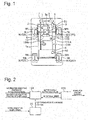
- Fig. 1 is a system diagram illustrating a configuration of an electric vehicle according to a first embodiment.
- the electric vehicle is a front-wheel drive vehicle, and includes front wheels FR and FL, which are drive wheels, and rear wheels RR and RL, which are trailer wheels.
- Each of the wheels is provided with a wheel cylinder W/C(FR), W/C(FL), W/C(RR), or W/C(RL) (also referred to as simply W/C), which generates a friction braking force by pressing brake pads against a brake rotor rotating integrally with a tire, and a wheel speed sensor 9(FR), 9(FL), 9(RR), or 9(RL) (also referred to as simply 9), which detects a wheel speed of each of the wheels.
- a hydraulic unit 5 is connected to the wheel cylinder W/C via a hydraulic pipe 5a, thereby forming a hydraulic brake. Further, the electric vehicle includes a steering angle sensor 110b (corresponding to a steering operation amount calculation unit), which calculates a steering angle indicating a steering amount by which a driver steers the vehicle.
- a steering angle sensor 110b corresponding to a steering operation amount calculation unit
- the hydraulic unit 5 includes a plurality of electromagnetic valves, a reservoir, a pump motor, and a brake controller 50, and controls a wheel cylinder hydraulic pressure at each of the wheels by controlling driving states of various kinds of electromagnetic valves and the pump motor based on instructions from the brake controller 50.
- the hydraulic unit 5 may be a known brake-by-wire unit, or may be a brake unit including a hydraulic circuit capable of realizing vehicle stability control.
- the type of the hydraulic unit 5 is not especially limited.
- a vehicle controller 110 (which will be described below) includes a yaw rate sensor 110a, which detects a yaw rate of the vehicle.
- An electric motor 1 which serves as a driving source, is provided with a resolver 2, which detects a rotational angle of the motor, and detects the rotational angle of the motor and also detects a rotational speed of the motor, based on a signal of the resolver.
- a differential gear 3 is connected to the electric motor 1 via a speed reduction mechanism 3a, and the front wheels FR and FL are connected to a drive shaft 4 connected to the differential gear 3.
- a high-voltage battery 6 and a battery controller 60 are mounted on a rear side of the vehicle. The high-voltage battery 6 supplies driving power to the electric motor 1 or collects regenerated power. The battery controller 60 monitors and controls a battery state of the high-voltage battery 6.
- An inverter 10 which is disposed between the high-voltage battery 6 and the electric motor 1, is controlled by a motor controller 100. Further, an auxiliary device battery 8 is connected to the high-voltage battery 6 via a DC-DC converter 7, and functions as a power source for driving the hydraulic unit 5.
- the electric vehicle according to the first embodiment is provided with a CAN communication line that is an in-vehicle communication line to which a plurality of controllers mounted on the vehicle is connected, whereby the steering angle sensor 110b, the brake controller 50, the vehicle controller 110, the battery controller 60, and the like are connected to one another so as to be able to communicate information.
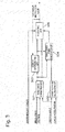
- Fig. 2 is a control block diagram illustrating a content of information transmitted and received by each of the controllers according to the first embodiment.
- the vehicle controller 110 receives inputs of information indicating a position of an accelerator pedal and information indicating a position of a shift lever, calculates a motor torque instruction value based on a basic driver request torque and results of a regenerative torque instruction value and a TCS torque instruction value output from the brake controller 50, and outputs the motor torque instruction value to the motor controller 100.
- the vehicle controller 110 outputs the driver request torque to the motor controller 100 when the regenerative torque instruction value and the TCS torque instruction value are not output from the brake controller 50, and outputs the regenerative torque instruction value and the TCS torque instruction value to the motor controller 100 when the regenerative torque instruction value and the TCS torque instruction value are output from the brake controller 50.
- the brake controller 50 receives inputs of information indicating a driver's intention to brake the vehicle, such as an ON/OFF state of a brake switch, a stroke amount of the brake pedal, or a pressing force applied to the brake pedal, which indicate an operation state of a brake pedal.
- the brake controller 50 further receives inputs of the steering angle, the yaw rate, and a signal indicating the wheel speed of each of the wheels. Then, the brake controller 50 calculates a signal indicating a vehicle body speed, a brake hydraulic pressure to be supplied to the wheel cylinder W/C, and the instruction value for a regenerative torque to be generated by the electric motor 1.
- the brake controller 50 calculates the TCS torque instruction value based on TCS control, which controls a driving slip state of each of the wheels to an appropriate slip state, and outputs the TCS torque instruction value to the vehicle controller 110.
- the motor controller 100 controls an activation state of the electric motor 1 based on the motor torque instruction value, and outputs information indicating an actual torque generated by the electric motor 1 to the vehicle controller 110, based on the detected actual motor torque, the rotational speed of the motor, a current value, and the like.
- Fig. 3 is a control block diagram illustrating a configuration of the TCS control for outputting the TCS torque instruction value that is provided in the brake controller according to the first embodiment.
- a wheel speed correction unit 501 corrects the wheel speed based on the wheel speed, the yaw rate, and the steering angle.
- Fig. 4 illustrates a vehicle mode for use in the correction of the wheel speed according to the first embodiment.
- Figs. 5 each illustrate a model that corrects the wheel speed when the vehicle is turning according to the first embodiment. In these models, each symbol is defined as illustrated in Fig. 4 .
- V Vehicle Body Speed
- Vx Longitudinal Component of Vehicle Body Speed
- Vy Lateral Component of Vehicle Body Speed
- Vfl Detected Value of Wheel Speed of Front Left Wheel
- Vfr Detected Value of Wheel Speed of Front Right Wheel
- Vrl Detected Value of Wheel Speed of Rear Left Wheel
- Vrr Detected Value of Wheel Speed of Rear Right Wheel
- dr track width
- the longitudinal component of the wheel speed can be calculated with use of the following expression as indicated by the model of the front left wheel illustrated in Fig. 5A .
- Vflx Vfl ⁇ Vy + ⁇ lf sin ⁇ f / cos ⁇ f + ⁇ dr / 2
- each piece of information can be acquired by a method that will be described below.
- the vehicle sideslip angle ⁇ is calculated from the yaw rate ⁇ , a lateral acceleration Ay, the longitudinal component Vx of the vehicle body speed, and the tire angle ⁇ f as illustrated in Fig. 5B .
- the lateral acceleration Ay is a value affected while the vehicle is running on a cant road surface, whereby the vehicle sideslip angle ⁇ is calculated with use of a corrected lateral acceleration Ayc, which is acquired by removing the influence of the cant road surface based on the yaw rate ⁇ and the longitudinal component Vx of the vehicle body speed.
- the wheel speed of each of the wheels is corrected as the wheel speed at a point of the center of gravity with use of the vehicle specifications indicating a position of each of the wheels, thereby outputting a corrected wheel speed.
- the wheel body speed is calculated based on this corrected wheel speed. For example, in the TCS control, an average of the corrected wheel speeds of the trailer wheels may be used as the vehicle body speed.
- This correction can correct, as a wheel speed at the point of the center of gravity of the vehicle, all of the influences due to the vehicle specifications, such as a difference in the wheel speed that might be generated between turning inner and outer wheels when the vehicle is turning, and a difference in the wheel speed that might be generated between a wheel that is steered and a wheel that is not steered, thereby acquiring the wheel speed from which the influences due to the vehicle specifications and the turn are removed.
- the corrected wheel speed does not vary relative to the vehicle body speed even when the vehicle is turning unless no slip occurs. Therefore, an incorrect determination, misinterpreting a change in the wheel speed that occurs along with the turn or the like as the occurrence of the slip is not made, which prevents, for example, the TCS control from intervening at an early timing.
- the brake controller may calculate, as a reference corrected wheel speed, such a value that each of the wheels exhibits the same value or matches within a predetermined range regardless of whether this is the value when the vehicle is running straight or when the vehicle is running while turning, provided that each of the wheels is in a non-slip state, and perform slip control based on how the corrected wheel speed of each of the wheels deviates from this reference corrected wheel speed.
- the slip control can be realized by correcting the wheel speed into such a value that the values converge for each of the wheels, and detecting the slip from the deviation from this convergence value.
- Vy is calculated from the vehicle sideslip angle ⁇ .
- another method 1 can correct the wheel speed, without use of ⁇ , from a relationship between the tire angle ⁇ f and the vehicle sideslip angle ⁇ because a relationship expressed by the following expression can be established between the tire angle ⁇ f and the vehicle sideslip angle ⁇ , assuming that a center of the turn is located on an extension of a rear axle.
- the vehicle model When ⁇ is estimated, like the method illustrated in Figs. 5 , the vehicle model should be acquired by a system identification method. However, the estimation accuracy reduces due to the influence of the road surface due to the cant road surface or the like, whereby the method illustrated in Figs. 5 requires the additional correction for eliminating the influence of the cant road surface.
- ⁇ which is the estimated value
- the method 1 does not require the correction of the influence on the cant road surface, which is required in the correction processing illustrated in Figs. 5 , thereby achieving the correction without being affected by an error in an estimation of a cant angle on the cant road surface.
- Fig. 6 illustrates a vehicle model for use in a correction of the wheel speed according to another method 2 as the correction of the wheel speed according to the first embodiment.
- the wheel speed of each of the wheels is corrected as the wheel speed at the position of the center of gravity.
- the wheel speed of each of the wheels is corrected based on the vehicle specifications indicating the position of each of the wheels, assuming that the center of the turn is located on the extension of the rear axle.
- V ′ fl Vfl ⁇ ⁇ + dr / 2 2 + lr 2 1 / 2 / ⁇ 2 + lf + lr 2 1 / 2
- V ′ fr Vfr ⁇ ⁇ + dr / 2 2 + lr 2 1 / 2 / ⁇ + dr 2 + lf + lr 2 1 / 2
- V ′ rl Vrl ⁇ ⁇ + dr / 2 2 + lr 2 1 / 2 / ⁇ + dr 2 + lf + lr 2 1 / 2
- V ′ rl Vrl ⁇ ⁇ + dr / 2 2 + lr 2 1 / 2 / ⁇
- V ′ rr Vrr ⁇ ⁇ + dr / 2 2 + lr 2 1 / 2 / ⁇ + dr
- the corrected wheel speeds V'fl, V'fr, V'rl, V'rr are each calculated as the speed at the center of gravity of the vehicle, but do not necessarily have to be calculated as the speed at the center of gravity and may be calculated in a different manner as long as they are calculated as the speed at an arbitrary point located at an equal relative distance from each of the wheels. This is because an important factor is not an absolute speed but a difference (a ratio) in speed between the wheel that is slipping and the wheel that is not slipping.
- a target slip ratio calculation unit 502 calculates a target slip ratio based on the steering angle and vehicle acceleration information.
- the vehicle acceleration information may be acquired from a longitudinal acceleration sensor, or may be calculated from a differential of the wheel speed or the vehicle speed.
- Fig. 7B is a control block diagram illustrating processing for calculating the target slip ratio according to the first embodiment.
- Fig. 7A is a characteristic diagram illustrating a frictional coefficient characteristic with respect to a slip ratio set for each road surface frictional coefficient (a road surface ⁇ ). When the vehicle is running on a road where ⁇ is high, an upper characteristic in Fig. 7A is selected. When the vehicle is running on a road where ⁇ is low, a lower characteristic in Fig. 7A is selected. Then, the slip ratio is set within a range that does not exceed the slip ratio capable of acquiring a highest frictional coefficient (a maximum frictional coefficient) in each of the characteristics.
- This characteristic diagram can be prepared by setting a result measured in advance.
- a straight running target slip ratio calculation unit 502a calculates a target slip ratio intended for a situation when the vehicle is running straight, based on the vehicle acceleration information.
- the vehicle acceleration is information corresponding to the road surface ⁇ .
- the straight running target slip ratio calculation unit 502a sets the target slip ratio capable of acquiring the maximum frictional coefficient according to the vehicle acceleration ( ⁇ the road surface ⁇ ).
- a steering gain calculation unit 502b calculates a steering gain according to the steering angle.
- the steering gain calculation unit 502b sets a large steering gain (for example, 1) if the steering angle is small, i.e., the steering angle remains around a neutral position, and sets a smaller gain as the steering angle increases, i.e., the steering angle is being widened further away from the neutral position into a turning state (in such a state that the steering operation amount is large).
- a gain multiplication unit 502c multiplies the target slip ratio output from the straight running target slip ratio calculation unit 502a by the steering gain, thereby outputting the final target slip ratio.
- Fig. 8 is a characteristic diagram illustrating a difference between when the vehicle is turning and when the vehicle is running straight in terms of the target slip ratio set by the processing for setting the target slip ratio according to the first embodiment.
- the target slip ratio is set within a range that is located around the maximum slip ratio capable of acquiring the maximum frictional coefficient and does not exceed the maximum slip ratio.
- the target slip ratio is set to a relatively lower slip ratio than when the vehicle is running straight.
- a TCS flag determination unit 503 determines whether to perform the TCS control, and turns on a TCS control ongoing flag if determining to perform the TCS control, while turning off the TCS control ongoing flag if determining not to perform the TCS control.
- Fig. 9 is a flowchart illustrating processing for determining the TCS control ongoing flag according to the first embodiment.
- step S1 the brake controller determines whether the TCS control ongoing flag is ON. If the TCS control ongoing flag is ON, the processing proceeds to step S5. If the TCS control ongoing flag is OFF, the processing proceeds to step S2.
- step S2 the brake controller determines whether the speed of the drive wheel is equal to or higher than a control intervention threshold value. If the drive wheel is equal to or higher than the control intervention threshold value, the processing proceeds to step S3. If not, the present control flow is ended.
- step S3 the brake controller turns on the TCS control ongoing flag.
- step S4 calculates a torque instruction value at the time of TCS control intervention. More specifically, the brake controller calculates this value by subtracting a predetermined torque from the current torque instruction value.
- step S5 the brake controller calculates the TCS control torque instruction value. More specifically, the brake controller calculates such a torque instruction value that a deviation between the speed of the drive wheel and the control intervention threshold value converge.
- step S6 the brake controller determines whether the deviation acquired by subtracting the TCS control torque instruction value from the driver request torque instruction value is equal to or smaller than an end torque deviation threshold value. If the deviation is equal to or smaller than the end torque deviation threshold value, the processing proceeds to step S7. If not, the processing proceeds to step S11. In other words, if the driver request torque instruction value largely deviates from the TCS control torque instruction value when the TCS control is ended and the torque value is changed to the driver request torque instruction value, a driving slip occurs again after the end of the control, making the driver feel uncomfortable. Therefore, the brake controller permits the end of the TCS control after the vehicle is brought into a state stably running without the driving slip or the like occurring again even when the TCS control is ended.
- step S7 the brake controller determines whether the speed of the drive wheel is equal to or lower than a control end speed. If the speed of the drive wheel is equal to or lower than the control end speed, the processing proceeds to step S8. If not, the processing proceeds to step S11.
- step S8 the brake controller determines whether a timer value of a TCS control end timer is equal to or larger than a predetermined value. If the timer value is equal to or larger than the predetermined value, the processing proceeds to step S9. If not, the processing proceeds to step S10.
- step S9 the brake controller turns off the TCS control ongoing flag.
- step S10 the brake controller increments the TCS control end timer.
- step S11 the brake controller clears the TCS control end timer.
- the TCS control end timer functions to end the TCS control after the predetermined time has elapsed after the end of the TCS control is determined to be approaching in step S6 or S7. Therefore, if the end of the TCS control is not approaching, the brake controller clears the TCS control end timer, and continues the TCS control.
- a target wheel speed calculation unit 504 calculates a target wheel speed from the current corrected wheel speed and the target slip ratio. More specifically, the target wheel speed calculation unit 504 adds to the vehicle body speed a value acquired by multiplying the vehicle body speed by the target slip ratio, thereby setting the target wheel speed.
- a PI control unit 505 performs feedback control so as to reduce the deviation between the corrected wheel speed and the target wheel speed to a predetermined value or smaller, thereby calculating the TCS torque instruction value.
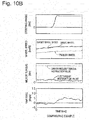
- Figs. 10 are each a timing chart when the driver performs the steering operation while the TCS control according to the first embodiment is in operation.
- Fig. 10A illustrates a timing chart according to the first embodiment
- Fig. 10B illustrates, as a comparative example, a timing chart when the control according to the turning state is not performed.
- a lower value according to the TCS torque instruction value than the driver request torque instruction value is output for the motor torque because the TCS control is in operation when the vehicle is running straight,. Therefore, the target slip ratio is set to a large value, also leading to a large deviation between the wheel speed of the drive wheel and the wheel speed of the trailer wheel.
- the present embodiment and the comparative example are not different from each other in terms of that.
- the target slip ratio is limited according to the steering angle in the first embodiment. This imitation leads to a reduction in the deviation between the wheel speed of the drive wheel and the wheel speed of the trailer wheel. Along therewith, the lateral force can be secured at the drive wheel, so that the yaw rate is solidly raised.
- the comparison example does not especially limit the target slip ratio, whereby the deviation between the wheel speed of the drive wheel and the wheel speed of the trailer wheel is almost the same as the deviation when the vehicle is running straight. In this case, the lateral force cannot be secured at the drive wheel, so that the yaw rate is not sufficiently raised.
- limiting the target slip ratio according to the turn can steadily secure the yaw rate according to the driver's intention to steer the vehicle.
- Figs. 11 are each a timing chart illustrating an effect of the processing for correcting the wheel speed according to the first embodiment.
- Fig. 11A illustrates a change in the steering angle over time.
- Fig. 11B illustrates a change in the yaw rate.
- Fig. 11C illustrates each of the wheel speeds when the wheel speed is not corrected.
- Fig. 11D illustrates the corrected wheel speed.
- a value varying according to the distance from the center of the turn is output as the wheel speed of each of the wheels according thereto. This is a value generated due to the vehicle specifications such as the track width and the wheelbase even when each of the wheels is appropriately running without excessively slipping.
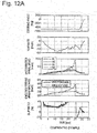
- Figs. 12 are each a timing chart when a slip occurs at the drive wheel when the vehicle is running while turning, and the TCS control is activated.
- Fig. 12A illustrates a timing chart when the TCS control is performed without the wheel speed corrected
- Fig. 12B illustrates a timing chart when the TCS control is performed with use of the corrected wheel speed according to the first embodiment.
- the wheel speed varies at each of the wheels when the vehicle is turning. If a driving slip occurs at the front left wheel in this state, the TCS control intervenes despite the fact that the deviation does not occur so much actually in view of the relationship between the average value of the wheel speeds of the drive wheels and the vehicle body speed.
- the first embodiment can bring about the following advantageous effects.
- the present invention is not limited to the above-described embodiment and may be configured in another manner.
- the wheel speed is corrected based on the point of the center of gravity of the vehicle or the center of the turn, but the correction of the wheel speed is not limited thereto and the wheel speed may be corrected based on an arbitrary point.
- the corrected wheel speed of each of the wheels exhibits generally the same value unless a slip occurs, if the influence of the vehicle specifications can be removed. Performing the slip control based on the deviation from this value can avoid creation of a discomfort, such as the early intervention of the slip control and a reduction in the torque due to the intervention.
- control at the time of the driving slip has been described referring to the control at the time of the driving slip, but the present control may be applied to the control at the time of braking as long as this control functions to control the slip amount based on the relationship between the wheel speed and the vehicle body speed.
- the embodiment has been described referring to the example in which the vehicle body speed is calculated based on the wheel speed, but the method for acquiring the vehicle body speed is not limited to the method using the wheel speed and the vehicle body speed may be acquired with use of a method that estimates an absolute vehicle body speed with use of an acceleration sensor or the like, or a method that estimates the vehicle body speed based on GPS information.
- the slip state is controlled based on the corrected wheel speed acquired by correcting in advance the influence due to the vehicle specifications indicating the position of each of the wheels, which can prevent the control from intervening at an early timing, thereby ensuring the drivability.
Landscapes
- Engineering & Computer Science (AREA)
- Transportation (AREA)
- Mechanical Engineering (AREA)
- Chemical & Material Sciences (AREA)
- Combustion & Propulsion (AREA)
- Physics & Mathematics (AREA)
- Fluid Mechanics (AREA)
- Regulating Braking Force (AREA)
- Control Of Driving Devices And Active Controlling Of Vehicle (AREA)
Claims (5)
- Fahrzeugsteuerungsgerät, das umfasst:eine Raddrehzahl-Berechnungseinheit (9), die konfiguriert ist, um eine Raddrehzahl von Rädern (FR, FL, RL, RR) zu berechnen;eine Korrektureinheit (501), die konfiguriert ist, um eine korrigierte Raddrehzahl zu berechnen, die durch Korrigieren der Raddrehzahl auf der Basis von Fahrzeugspezifikationen gewonnen wird, die eine Position von jedem der Räder (FR, FL, RL, RR) anzeigen,eine Fahrzeugkarosserie-Geschwindigkeitsberechnungseinheit (50), die konfiguriert ist, um eine Fahrzeugkarosserie-Geschwindigkeit auf der Basis der berechneten korrigierten Raddrehzahl zu berechnen;eine Schlupfregeleinheit, die konfiguriert ist, um einen Schlupfzustand der Räder (FR, FL, RL, RR) entsprechend den Zuständen der korrigierten Raddrehzahl und der Fahrzeugkarosserie-Geschwindigkeit zu regeln;eine Lenkvorgangumfangs-Berechnungseinheit (110b), die konfiguriert ist, um einen Lenkvorgangumfang zu berechnen; undeine Gierratenberechnungseinheit (110a), die konfiguriert ist, um eine Gierrate eines Fahrzeugs zu berechnen,dadurch gekennzeichnet, dass die Schlupfregeleinheit den Schlupfzustand von jedem der Räder (FR, FL, RL, RR) in einer solchen Weise steuert, dass das Soll-Schlupfverhältnis abnimmt, wenn der berechnete Lenkvorgangumfang zunimmt, unddie Korrektureinheit (501) die korrigierte Raddrehzahl auf der Basis des Lenkvorgangumfangs und der Gierrate berechnet.
- Fahrzeugsteuerungsgerät nach Anspruch 1, wobei die Korrektureinheit (501) die Raddrehzahl auf der Basis eines Punktes von einem Schwerpunkt des Fahrzeugs korrigiert.
- Fahrzeugsteuerungsgerät nach Anspruch 1, wobei die Korrektureinheit (501) die Raddrehzahl auf der Basis eines Punktes auf einer Verlängerung einer Hinterachse korrigiert.
- Fahrzeugsteuerungsgerät nach Anspruch 3, wobei die Korrektureinheit (501) die Raddrehzahl auf der Basis eines Kurvenmittelpunktes korrigiert, der anhand der Raddrehzahl von jedem der Räder (FR, FL, RL, RR) geschätzt wird.
- Fahrzeugsteuerungsgerät nach Anspruch 1, wobei die Korrektureinheit (501) konfiguriert ist, um eine zusammen mit einer Kurve erzeugte Raddrehzahl-Änderungskomponente anhand einer Raddrehzahl von jedem der Räder (FR, FL, RL, RR) zu entfernen, um die korrigierte Raddrehzahl zu berechnen; und
eine Schlupfregeleinheit konfiguriert ist, um einen Schlupfzustand der Räder (FR, FL, RL, RR) entsprechend Zuständen der Steuerungsraddrehzahl und der Fahrzeugkarosserie-Geschwindigkeit zu regeln.
Applications Claiming Priority (2)
| Application Number | Priority Date | Filing Date | Title |
|---|---|---|---|
| JP2014104012A JP6364675B2 (ja) | 2014-05-20 | 2014-05-20 | 車両制御装置 |
| PCT/JP2015/063781 WO2015178276A1 (ja) | 2014-05-20 | 2015-05-13 | 車両制御装置 |
Publications (3)
| Publication Number | Publication Date |
|---|---|
| EP3147166A1 EP3147166A1 (de) | 2017-03-29 |
| EP3147166A4 EP3147166A4 (de) | 2017-06-21 |
| EP3147166B1 true EP3147166B1 (de) | 2021-05-05 |
Family
ID=54553949
Family Applications (1)
| Application Number | Title | Priority Date | Filing Date |
|---|---|---|---|
| EP15795457.9A Active EP3147166B1 (de) | 2014-05-20 | 2015-05-13 | Fahrzeugsteuerungsvorrichtung |
Country Status (6)
| Country | Link |
|---|---|
| US (1) | US20170137004A1 (de) |
| EP (1) | EP3147166B1 (de) |
| JP (1) | JP6364675B2 (de) |
| KR (1) | KR101882121B1 (de) |
| CN (1) | CN106232438A (de) |
| WO (1) | WO2015178276A1 (de) |
Families Citing this family (9)
| Publication number | Priority date | Publication date | Assignee | Title |
|---|---|---|---|---|
| DE102017111077A1 (de) * | 2017-05-22 | 2018-11-22 | Lsp Innovative Automotive Systems Gmbh | Bremsvorrichtung, insbesondere für elektrisch angetriebene Kraftfahrzeuge |
| CN108223468A (zh) * | 2018-01-17 | 2018-06-29 | 广西柳工机械股份有限公司 | 平地机前轮驱动控制系统 |
| US10308259B1 (en) | 2018-06-11 | 2019-06-04 | Caterpillar Inc. | Slip determining system and methods for a machine |
| CN110375770A (zh) * | 2018-11-02 | 2019-10-25 | 北京京东尚科信息技术有限公司 | 一种定位误差的校准方法和装置 |
| US11891037B2 (en) | 2019-01-31 | 2024-02-06 | Toyota Motor Engineering & Manufacturing North America, Inc. | Systems, vehicles, and methods for vehicle stability control and trailer brake control collaboration |
| US11872885B2 (en) * | 2019-10-31 | 2024-01-16 | Deere & Company | Trailing vehicle traction control system with force increase control |
| CN112277929B (zh) * | 2020-11-05 | 2022-03-01 | 中国第一汽车股份有限公司 | 一种车辆车轮滑转率控制方法、装置、车辆及存储介质 |
| KR20220086734A (ko) * | 2020-12-16 | 2022-06-24 | 현대자동차주식회사 | 최대 노면 마찰계수 추정방법 |
| CN114013504B (zh) * | 2021-12-09 | 2023-03-24 | 江苏徐工工程机械研究院有限公司 | 车辆转向参数测量校准方法、系统、介质及自动驾驶车辆 |
Family Cites Families (19)
| Publication number | Priority date | Publication date | Assignee | Title |
|---|---|---|---|---|
| JPS62113652A (ja) * | 1985-11-13 | 1987-05-25 | Nissan Motor Co Ltd | 4輪操舵車両 |
| US5329805A (en) * | 1988-07-18 | 1994-07-19 | Honda Giken Kogyo Kabushiki Kaisha | Vehicle body speed estimating method in anti-lock control system for vehicle |
| DE69100663T3 (de) * | 1990-01-31 | 1998-12-10 | Mazda Motor Corp., Hiroshima | Schlupfregelsystem für ein Kraftfahrzeug. |
| JP2869661B2 (ja) * | 1990-01-31 | 1999-03-10 | マツダ株式会社 | 車両のスリップ制御装置 |
| JP2926601B2 (ja) * | 1990-03-23 | 1999-07-28 | アイシン精機株式会社 | リターディング制御装置 |
| JP3170931B2 (ja) * | 1993-02-19 | 2001-05-28 | 日産自動車株式会社 | 制動力制御装置 |
| JP3527290B2 (ja) * | 1994-09-16 | 2004-05-17 | 日産自動車株式会社 | アンチスキッド制御装置 |
| JP3633120B2 (ja) * | 1996-07-18 | 2005-03-30 | 日産自動車株式会社 | 車体速および路面摩擦係数推定装置 |
| JP3290359B2 (ja) * | 1996-07-22 | 2002-06-10 | 三菱電機株式会社 | アンチロックブレーキ制御装置 |
| KR100254224B1 (ko) * | 1996-11-19 | 2000-06-01 | 정몽규 | 자동차의 정지 제어시 휠 속 검출방법 |
| JPH10264798A (ja) * | 1997-03-27 | 1998-10-06 | Mazda Motor Corp | 車両の姿勢制御装置 |
| US6185497B1 (en) * | 1998-03-20 | 2001-02-06 | Denso Corporation | Apparatus for controlling behavior of vehicle using brakes |
| JP4320827B2 (ja) * | 1998-03-20 | 2009-08-26 | 株式会社デンソー | 車体挙動制御装置 |
| KR100774122B1 (ko) * | 2003-05-13 | 2007-11-08 | 주식회사 만도 | 차량의 안정성 제어방법 |
| JP4232843B1 (ja) * | 2007-10-04 | 2009-03-04 | トヨタ自動車株式会社 | 車両転舵制御装置 |
| JP5098674B2 (ja) * | 2008-01-31 | 2012-12-12 | 株式会社アドヴィックス | 車体速度演算装置 |
| EP2394876B1 (de) * | 2009-03-30 | 2014-10-15 | Honda Motor Co., Ltd. | Vorrichtung zur messung der statusquantität von rutschbewegungen eines fahrzeugs |
| JP5508842B2 (ja) * | 2009-12-28 | 2014-06-04 | 株式会社アドヴィックス | 車両の速度制御装置 |
| JP5880927B2 (ja) * | 2011-10-06 | 2016-03-09 | 株式会社ジェイテクト | 車両用姿勢制御装置 |
-
2014
- 2014-05-20 JP JP2014104012A patent/JP6364675B2/ja active Active
-
2015
- 2015-05-13 EP EP15795457.9A patent/EP3147166B1/de active Active
- 2015-05-13 KR KR1020167026232A patent/KR101882121B1/ko active Active
- 2015-05-13 CN CN201580020780.9A patent/CN106232438A/zh active Pending
- 2015-05-13 WO PCT/JP2015/063781 patent/WO2015178276A1/ja not_active Ceased
- 2015-05-13 US US15/308,786 patent/US20170137004A1/en not_active Abandoned
Also Published As
| Publication number | Publication date |
|---|---|
| EP3147166A4 (de) | 2017-06-21 |
| EP3147166A1 (de) | 2017-03-29 |
| KR20160125473A (ko) | 2016-10-31 |
| JP2015217861A (ja) | 2015-12-07 |
| CN106232438A (zh) | 2016-12-14 |
| WO2015178276A1 (ja) | 2015-11-26 |
| KR101882121B1 (ko) | 2018-07-25 |
| JP6364675B2 (ja) | 2018-08-01 |
| US20170137004A1 (en) | 2017-05-18 |
Similar Documents
| Publication | Publication Date | Title |
|---|---|---|
| EP3147166B1 (de) | Fahrzeugsteuerungsvorrichtung | |
| US8764124B2 (en) | Brake control apparatus | |
| US8977434B2 (en) | Vehicle attitude control system | |
| EP3275723A1 (de) | Fahrzeugsteuerungsvorrichtung und fahrzeugsteuerungsverfahren | |
| US7337873B2 (en) | Steering control apparatus for a vehicle | |
| US11161499B2 (en) | Vehicle driving assistance device | |
| KR102881929B1 (ko) | 차량의 자세 제어 방법 | |
| CN108621787A (zh) | 四轮驱动车辆的控制装置 | |
| JP5636825B2 (ja) | 車重推定装置 | |
| US20050205339A1 (en) | Steering control apparatus for a vehicle | |
| KR101315023B1 (ko) | 차량의 기준 속도 추정 방법 | |
| JP4284210B2 (ja) | 車両の操舵制御装置 | |
| JP5194430B2 (ja) | 車両の4輪操舵制御装置 | |
| JP5849708B2 (ja) | 車両の駆動力制御装置 | |
| JP4630039B2 (ja) | 車両の操舵制御装置 | |
| JP5194429B2 (ja) | 車両の4輪操舵制御装置 | |
| KR100751216B1 (ko) | 차량의 안정성 제어 시스템 | |
| JP6056240B2 (ja) | 車両の挙動制御装置 | |
| KR100806077B1 (ko) | 차량 휠의 기준속도 산출방법 | |
| JP4685407B2 (ja) | 車輌の挙動制御装置 | |
| JP4333327B2 (ja) | 車輌の車体速度推定制御装置 | |
| JP5396116B2 (ja) | 摩擦状態推定装置 | |
| KR20120137033A (ko) | 차량의 자세제어방법 |
Legal Events
| Date | Code | Title | Description |
|---|---|---|---|
| STAA | Information on the status of an ep patent application or granted ep patent |
Free format text: STATUS: THE INTERNATIONAL PUBLICATION HAS BEEN MADE |
|
| PUAI | Public reference made under article 153(3) epc to a published international application that has entered the european phase |
Free format text: ORIGINAL CODE: 0009012 |
|
| STAA | Information on the status of an ep patent application or granted ep patent |
Free format text: STATUS: REQUEST FOR EXAMINATION WAS MADE |
|
| 17P | Request for examination filed |
Effective date: 20161107 |
|
| AK | Designated contracting states |
Kind code of ref document: A1 Designated state(s): AL AT BE BG CH CY CZ DE DK EE ES FI FR GB GR HR HU IE IS IT LI LT LU LV MC MK MT NL NO PL PT RO RS SE SI SK SM TR |
|
| AX | Request for extension of the european patent |
Extension state: BA ME |
|
| A4 | Supplementary search report drawn up and despatched |
Effective date: 20170524 |
|
| RIC1 | Information provided on ipc code assigned before grant |
Ipc: B60T 8/175 20060101AFI20170518BHEP Ipc: B60T 8/171 20060101ALI20170518BHEP |
|
| DAV | Request for validation of the european patent (deleted) | ||
| DAX | Request for extension of the european patent (deleted) | ||
| REG | Reference to a national code |
Ref country code: DE Ref legal event code: R079 Ref document number: 602015069033 Country of ref document: DE Free format text: PREVIOUS MAIN CLASS: B60T0008175000 Ipc: B60T0008175500 |
|
| STAA | Information on the status of an ep patent application or granted ep patent |
Free format text: STATUS: EXAMINATION IS IN PROGRESS |
|
| RIC1 | Information provided on ipc code assigned before grant |
Ipc: B60T 8/1755 20060101AFI20200211BHEP |
|
| 17Q | First examination report despatched |
Effective date: 20200226 |
|
| GRAP | Despatch of communication of intention to grant a patent |
Free format text: ORIGINAL CODE: EPIDOSNIGR1 |
|
| STAA | Information on the status of an ep patent application or granted ep patent |
Free format text: STATUS: GRANT OF PATENT IS INTENDED |
|
| INTG | Intention to grant announced |
Effective date: 20210115 |
|
| GRAS | Grant fee paid |
Free format text: ORIGINAL CODE: EPIDOSNIGR3 |
|
| GRAA | (expected) grant |
Free format text: ORIGINAL CODE: 0009210 |
|
| STAA | Information on the status of an ep patent application or granted ep patent |
Free format text: STATUS: THE PATENT HAS BEEN GRANTED |
|
| RAP3 | Party data changed (applicant data changed or rights of an application transferred) |
Owner name: HITACHI ASTEMO, LTD. |
|
| AK | Designated contracting states |
Kind code of ref document: B1 Designated state(s): AL AT BE BG CH CY CZ DE DK EE ES FI FR GB GR HR HU IE IS IT LI LT LU LV MC MK MT NL NO PL PT RO RS SE SI SK SM TR |
|
| REG | Reference to a national code |
Ref country code: GB Ref legal event code: FG4D |
|
| REG | Reference to a national code |
Ref country code: CH Ref legal event code: EP |
|
| REG | Reference to a national code |
Ref country code: AT Ref legal event code: REF Ref document number: 1389456 Country of ref document: AT Kind code of ref document: T Effective date: 20210515 |
|
| REG | Reference to a national code |
Ref country code: DE Ref legal event code: R096 Ref document number: 602015069033 Country of ref document: DE |
|
| REG | Reference to a national code |
Ref country code: IE Ref legal event code: FG4D |
|
| REG | Reference to a national code |
Ref country code: LT Ref legal event code: MG9D |
|
| REG | Reference to a national code |
Ref country code: AT Ref legal event code: MK05 Ref document number: 1389456 Country of ref document: AT Kind code of ref document: T Effective date: 20210505 |
|
| PG25 | Lapsed in a contracting state [announced via postgrant information from national office to epo] |
Ref country code: LT Free format text: LAPSE BECAUSE OF FAILURE TO SUBMIT A TRANSLATION OF THE DESCRIPTION OR TO PAY THE FEE WITHIN THE PRESCRIBED TIME-LIMIT Effective date: 20210505 Ref country code: FI Free format text: LAPSE BECAUSE OF FAILURE TO SUBMIT A TRANSLATION OF THE DESCRIPTION OR TO PAY THE FEE WITHIN THE PRESCRIBED TIME-LIMIT Effective date: 20210505 Ref country code: BG Free format text: LAPSE BECAUSE OF FAILURE TO SUBMIT A TRANSLATION OF THE DESCRIPTION OR TO PAY THE FEE WITHIN THE PRESCRIBED TIME-LIMIT Effective date: 20210805 Ref country code: AT Free format text: LAPSE BECAUSE OF FAILURE TO SUBMIT A TRANSLATION OF THE DESCRIPTION OR TO PAY THE FEE WITHIN THE PRESCRIBED TIME-LIMIT Effective date: 20210505 Ref country code: HR Free format text: LAPSE BECAUSE OF FAILURE TO SUBMIT A TRANSLATION OF THE DESCRIPTION OR TO PAY THE FEE WITHIN THE PRESCRIBED TIME-LIMIT Effective date: 20210505 |
|
| PG25 | Lapsed in a contracting state [announced via postgrant information from national office to epo] |
Ref country code: IS Free format text: LAPSE BECAUSE OF FAILURE TO SUBMIT A TRANSLATION OF THE DESCRIPTION OR TO PAY THE FEE WITHIN THE PRESCRIBED TIME-LIMIT Effective date: 20210905 Ref country code: GR Free format text: LAPSE BECAUSE OF FAILURE TO SUBMIT A TRANSLATION OF THE DESCRIPTION OR TO PAY THE FEE WITHIN THE PRESCRIBED TIME-LIMIT Effective date: 20210806 Ref country code: LV Free format text: LAPSE BECAUSE OF FAILURE TO SUBMIT A TRANSLATION OF THE DESCRIPTION OR TO PAY THE FEE WITHIN THE PRESCRIBED TIME-LIMIT Effective date: 20210505 Ref country code: PL Free format text: LAPSE BECAUSE OF FAILURE TO SUBMIT A TRANSLATION OF THE DESCRIPTION OR TO PAY THE FEE WITHIN THE PRESCRIBED TIME-LIMIT Effective date: 20210505 Ref country code: PT Free format text: LAPSE BECAUSE OF FAILURE TO SUBMIT A TRANSLATION OF THE DESCRIPTION OR TO PAY THE FEE WITHIN THE PRESCRIBED TIME-LIMIT Effective date: 20210906 Ref country code: NO Free format text: LAPSE BECAUSE OF FAILURE TO SUBMIT A TRANSLATION OF THE DESCRIPTION OR TO PAY THE FEE WITHIN THE PRESCRIBED TIME-LIMIT Effective date: 20210805 Ref country code: ES Free format text: LAPSE BECAUSE OF FAILURE TO SUBMIT A TRANSLATION OF THE DESCRIPTION OR TO PAY THE FEE WITHIN THE PRESCRIBED TIME-LIMIT Effective date: 20210505 Ref country code: SE Free format text: LAPSE BECAUSE OF FAILURE TO SUBMIT A TRANSLATION OF THE DESCRIPTION OR TO PAY THE FEE WITHIN THE PRESCRIBED TIME-LIMIT Effective date: 20210505 Ref country code: RS Free format text: LAPSE BECAUSE OF FAILURE TO SUBMIT A TRANSLATION OF THE DESCRIPTION OR TO PAY THE FEE WITHIN THE PRESCRIBED TIME-LIMIT Effective date: 20210505 |
|
| REG | Reference to a national code |
Ref country code: NL Ref legal event code: MP Effective date: 20210505 |
|
| REG | Reference to a national code |
Ref country code: CH Ref legal event code: PL |
|
| PG25 | Lapsed in a contracting state [announced via postgrant information from national office to epo] |
Ref country code: NL Free format text: LAPSE BECAUSE OF FAILURE TO SUBMIT A TRANSLATION OF THE DESCRIPTION OR TO PAY THE FEE WITHIN THE PRESCRIBED TIME-LIMIT Effective date: 20210505 |
|
| PG25 | Lapsed in a contracting state [announced via postgrant information from national office to epo] |
Ref country code: DK Free format text: LAPSE BECAUSE OF FAILURE TO SUBMIT A TRANSLATION OF THE DESCRIPTION OR TO PAY THE FEE WITHIN THE PRESCRIBED TIME-LIMIT Effective date: 20210505 Ref country code: CZ Free format text: LAPSE BECAUSE OF FAILURE TO SUBMIT A TRANSLATION OF THE DESCRIPTION OR TO PAY THE FEE WITHIN THE PRESCRIBED TIME-LIMIT Effective date: 20210505 Ref country code: EE Free format text: LAPSE BECAUSE OF FAILURE TO SUBMIT A TRANSLATION OF THE DESCRIPTION OR TO PAY THE FEE WITHIN THE PRESCRIBED TIME-LIMIT Effective date: 20210505 Ref country code: SK Free format text: LAPSE BECAUSE OF FAILURE TO SUBMIT A TRANSLATION OF THE DESCRIPTION OR TO PAY THE FEE WITHIN THE PRESCRIBED TIME-LIMIT Effective date: 20210505 Ref country code: SM Free format text: LAPSE BECAUSE OF FAILURE TO SUBMIT A TRANSLATION OF THE DESCRIPTION OR TO PAY THE FEE WITHIN THE PRESCRIBED TIME-LIMIT Effective date: 20210505 Ref country code: RO Free format text: LAPSE BECAUSE OF FAILURE TO SUBMIT A TRANSLATION OF THE DESCRIPTION OR TO PAY THE FEE WITHIN THE PRESCRIBED TIME-LIMIT Effective date: 20210505 Ref country code: CH Free format text: LAPSE BECAUSE OF NON-PAYMENT OF DUE FEES Effective date: 20210531 Ref country code: LU Free format text: LAPSE BECAUSE OF NON-PAYMENT OF DUE FEES Effective date: 20210513 Ref country code: LI Free format text: LAPSE BECAUSE OF NON-PAYMENT OF DUE FEES Effective date: 20210531 |
|
| REG | Reference to a national code |
Ref country code: DE Ref legal event code: R097 Ref document number: 602015069033 Country of ref document: DE |
|
| REG | Reference to a national code |
Ref country code: BE Ref legal event code: MM Effective date: 20210531 |
|
| PLBE | No opposition filed within time limit |
Free format text: ORIGINAL CODE: 0009261 |
|
| STAA | Information on the status of an ep patent application or granted ep patent |
Free format text: STATUS: NO OPPOSITION FILED WITHIN TIME LIMIT |
|
| PG25 | Lapsed in a contracting state [announced via postgrant information from national office to epo] |
Ref country code: MC Free format text: LAPSE BECAUSE OF FAILURE TO SUBMIT A TRANSLATION OF THE DESCRIPTION OR TO PAY THE FEE WITHIN THE PRESCRIBED TIME-LIMIT Effective date: 20210505 |
|
| 26N | No opposition filed |
Effective date: 20220208 |
|
| GBPC | Gb: european patent ceased through non-payment of renewal fee |
Effective date: 20210805 |
|
| PG25 | Lapsed in a contracting state [announced via postgrant information from national office to epo] |
Ref country code: IE Free format text: LAPSE BECAUSE OF NON-PAYMENT OF DUE FEES Effective date: 20210513 |
|
| PG25 | Lapsed in a contracting state [announced via postgrant information from national office to epo] |
Ref country code: IS Free format text: LAPSE BECAUSE OF FAILURE TO SUBMIT A TRANSLATION OF THE DESCRIPTION OR TO PAY THE FEE WITHIN THE PRESCRIBED TIME-LIMIT Effective date: 20210905 Ref country code: FR Free format text: LAPSE BECAUSE OF NON-PAYMENT OF DUE FEES Effective date: 20210705 Ref country code: AL Free format text: LAPSE BECAUSE OF FAILURE TO SUBMIT A TRANSLATION OF THE DESCRIPTION OR TO PAY THE FEE WITHIN THE PRESCRIBED TIME-LIMIT Effective date: 20210505 |
|
| PG25 | Lapsed in a contracting state [announced via postgrant information from national office to epo] |
Ref country code: IT Free format text: LAPSE BECAUSE OF FAILURE TO SUBMIT A TRANSLATION OF THE DESCRIPTION OR TO PAY THE FEE WITHIN THE PRESCRIBED TIME-LIMIT Effective date: 20210505 Ref country code: GB Free format text: LAPSE BECAUSE OF NON-PAYMENT OF DUE FEES Effective date: 20210805 Ref country code: BE Free format text: LAPSE BECAUSE OF NON-PAYMENT OF DUE FEES Effective date: 20210531 |
|
| PG25 | Lapsed in a contracting state [announced via postgrant information from national office to epo] |
Ref country code: HU Free format text: LAPSE BECAUSE OF FAILURE TO SUBMIT A TRANSLATION OF THE DESCRIPTION OR TO PAY THE FEE WITHIN THE PRESCRIBED TIME-LIMIT; INVALID AB INITIO Effective date: 20150513 |
|
| PG25 | Lapsed in a contracting state [announced via postgrant information from national office to epo] |
Ref country code: CY Free format text: LAPSE BECAUSE OF FAILURE TO SUBMIT A TRANSLATION OF THE DESCRIPTION OR TO PAY THE FEE WITHIN THE PRESCRIBED TIME-LIMIT Effective date: 20210505 |
|
| PG25 | Lapsed in a contracting state [announced via postgrant information from national office to epo] |
Ref country code: MK Free format text: LAPSE BECAUSE OF FAILURE TO SUBMIT A TRANSLATION OF THE DESCRIPTION OR TO PAY THE FEE WITHIN THE PRESCRIBED TIME-LIMIT Effective date: 20210505 |
|
| PG25 | Lapsed in a contracting state [announced via postgrant information from national office to epo] |
Ref country code: TR Free format text: LAPSE BECAUSE OF FAILURE TO SUBMIT A TRANSLATION OF THE DESCRIPTION OR TO PAY THE FEE WITHIN THE PRESCRIBED TIME-LIMIT Effective date: 20210505 |
|
| PG25 | Lapsed in a contracting state [announced via postgrant information from national office to epo] |
Ref country code: MT Free format text: LAPSE BECAUSE OF FAILURE TO SUBMIT A TRANSLATION OF THE DESCRIPTION OR TO PAY THE FEE WITHIN THE PRESCRIBED TIME-LIMIT Effective date: 20210505 |
|
| PGFP | Annual fee paid to national office [announced via postgrant information from national office to epo] |
Ref country code: DE Payment date: 20250402 Year of fee payment: 11 |