EP3147057B1 - Outil de coupe rotatif indexable - Google Patents
Outil de coupe rotatif indexable Download PDFInfo
- Publication number
- EP3147057B1 EP3147057B1 EP15821813.1A EP15821813A EP3147057B1 EP 3147057 B1 EP3147057 B1 EP 3147057B1 EP 15821813 A EP15821813 A EP 15821813A EP 3147057 B1 EP3147057 B1 EP 3147057B1
- Authority
- EP
- European Patent Office
- Prior art keywords
- cutting
- cutting edge
- major
- inserts
- tool
- Prior art date
- Legal status (The legal status is an assumption and is not a legal conclusion. Google has not performed a legal analysis and makes no representation as to the accuracy of the status listed.)
- Active
Links
- 230000002093 peripheral effect Effects 0.000 claims description 17
- 239000002826 coolant Substances 0.000 description 9
- 239000000463 material Substances 0.000 description 5
- 230000000694 effects Effects 0.000 description 4
- 238000010586 diagram Methods 0.000 description 3
- 229910052582 BN Inorganic materials 0.000 description 2
- PZNSFCLAULLKQX-UHFFFAOYSA-N Boron nitride Chemical compound N#B PZNSFCLAULLKQX-UHFFFAOYSA-N 0.000 description 2
- 239000011248 coating agent Substances 0.000 description 2
- 238000000576 coating method Methods 0.000 description 2
- 230000014509 gene expression Effects 0.000 description 2
- 230000004048 modification Effects 0.000 description 2
- 238000012986 modification Methods 0.000 description 2
- 230000000452 restraining effect Effects 0.000 description 2
- 230000001154 acute effect Effects 0.000 description 1
- 239000000919 ceramic Substances 0.000 description 1
- 239000011195 cermet Substances 0.000 description 1
- 238000001816 cooling Methods 0.000 description 1
- 229910003460 diamond Inorganic materials 0.000 description 1
- 239000010432 diamond Substances 0.000 description 1
- 238000007599 discharging Methods 0.000 description 1
- 238000003754 machining Methods 0.000 description 1
- 238000005728 strengthening Methods 0.000 description 1
- 230000003746 surface roughness Effects 0.000 description 1
Images


Classifications
-
- B—PERFORMING OPERATIONS; TRANSPORTING
- B23—MACHINE TOOLS; METAL-WORKING NOT OTHERWISE PROVIDED FOR
- B23C—MILLING
- B23C5/00—Milling-cutters
- B23C5/02—Milling-cutters characterised by the shape of the cutter
- B23C5/10—Shank-type cutters, i.e. with an integral shaft
- B23C5/109—Shank-type cutters, i.e. with an integral shaft with removable cutting inserts
-
- B—PERFORMING OPERATIONS; TRANSPORTING
- B23—MACHINE TOOLS; METAL-WORKING NOT OTHERWISE PROVIDED FOR
- B23C—MILLING
- B23C5/00—Milling-cutters
- B23C5/02—Milling-cutters characterised by the shape of the cutter
- B23C5/10—Shank-type cutters, i.e. with an integral shaft
-
- B—PERFORMING OPERATIONS; TRANSPORTING
- B23—MACHINE TOOLS; METAL-WORKING NOT OTHERWISE PROVIDED FOR
- B23C—MILLING
- B23C5/00—Milling-cutters
- B23C5/16—Milling-cutters characterised by physical features other than shape
- B23C5/20—Milling-cutters characterised by physical features other than shape with removable cutter bits or teeth or cutting inserts
- B23C5/202—Plate-like cutting inserts with special form
-
- B—PERFORMING OPERATIONS; TRANSPORTING
- B23—MACHINE TOOLS; METAL-WORKING NOT OTHERWISE PROVIDED FOR
- B23C—MILLING
- B23C2200/00—Details of milling cutting inserts
- B23C2200/04—Overall shape
- B23C2200/0477—Triangular
-
- B—PERFORMING OPERATIONS; TRANSPORTING
- B23—MACHINE TOOLS; METAL-WORKING NOT OTHERWISE PROVIDED FOR
- B23C—MILLING
- B23C2200/00—Details of milling cutting inserts
- B23C2200/20—Top or side views of the cutting edge
- B23C2200/206—Cutting edges having a wave-form
-
- B—PERFORMING OPERATIONS; TRANSPORTING
- B23—MACHINE TOOLS; METAL-WORKING NOT OTHERWISE PROVIDED FOR
- B23C—MILLING
- B23C2210/00—Details of milling cutters
- B23C2210/28—Arrangement of teeth
-
- B—PERFORMING OPERATIONS; TRANSPORTING
- B23—MACHINE TOOLS; METAL-WORKING NOT OTHERWISE PROVIDED FOR
- B23C—MILLING
- B23C2220/00—Details of milling processes
- B23C2220/60—Roughing
Definitions
- the present invention relates to an indexable rotary cutting tool. More specifically, the present invention relates to an indexable rotary cutting tool in the form of a roughing cutter on which a plurality of cutting inserts is removably mounted.
- an indexable rotary cutting tool having a cylindrical tool body provided with a plurality of grooves extending from its proximal end toward its distal end in a peripheral surface of the tool body, each groove being configured to allow a plurality of cutting inserts to be removably mounted therein in a direction of the tool rotational axis.
- the rotary cutting tool having such shape is called a roughing cutter.
- the roughing cutter since the plurality of cutting inserts is aligned in the direction of tool rotational axis, a substantial length of the cutting edges is large and the tool can therefore form large depth of cut. Accordingly, highly efficient machining can be achieved.
- Patent Document 1 discloses a roughing cutter on which quadrangular cutting inserts each having a cutting edge having a wave shape in a side view are mounted.
- the cutting inserts are arranged such that: in a relationship in each groove, they are aligned with an interval therebetween in an axial direction; and in a relationship between the plurality of grooves, the cutting edges having a wave shape that are aligned in the axial direction form consecutive rows of cutting edges in a rotational trajectory around the axis.
- Patent Document 1 states that the wave shape cutting edges cause chips to be separated into smaller pieces than the length of the cutting edge, and therefore the disposal capacity of the chips can be improved.
- JP 2013 202770 A discloses an indexable rotary cutting tool according to the preamble of claim 1, comprising a plurality of cutting inserts that are mounted on the end mill body in a state of being shifted in the axial direction, and in the locus of rotation about the axis, these cutting inserts are arranged so that the phases of the waveforms of wavy cutting blades are made continuous with one another, and thus a plurality of lines of wavy cutting blades whose phases of the waveforms are shifted from one another is formed.
- Patent Document 1 JP2008-068345 A
- a positive-type triangular cutting insert has one more available corner as compared to the conventional quadrangular cutting insert, and is therefore economically efficient.
- a roughing cutter employing such triangular cutting inserts is used to perform cutting involving a feed motion in the axial direction of the tool (such as ramp cutting)
- the arrangement of cutting inserts as disclosed in Patent Document 1 will cause the following problem.
- an inner cutting edge used for ramp cutting or the like constitutes part of a major cutting edge.
- the "inner cutting edge” is a cutting edge that does not have any function during a normal lateral feeding but is used when the tool is fed also in the axial direction of the tool, as in the ramp cutting.
- the inner cutting edge is provided on the side opposite to a side, with which a corner cutting edge is connected, of a minor cutting edge involved in cutting, in a state in which the cutting inserts are attached to the tool body.
- the present invention has been made in light of the above problem and an object of the present invention is to provide an indexable cutting tool in the form of a roughing cutter that, even when cutting inserts having wave shape cutting edges and having cutting edge portions, being part of its major cutting edges, serving also as inner cutting edges are mounted on the indexable cutting tool, is capable of suppressing breakages in such cutting edge portions.
- the present invention provides an indexable rotary cutting tool (10) comprising: a substantially cylindrical tool body (20) having a rotational axis (O); and cutting inserts (30) mounted on the tool body (20), in which a plurality of grooves (27) is formed in a peripheral surface (23) of the tool body (20), a plurality of insert seats (28) is formed in the grooves (27), and the cutting inserts (30) are removably arranged onto the insert seats (27), wherein: the cutting inserts (30) each have a rake surface (31) and a flank (33) intersecting with the rake surface (31), and a major cutting edge (34), a corner cutting edge (37) connected to the major cutting edge (34), and a minor cutting edge (35) connected to the corner cutting edge (37), are formed in an intersecting edge between the rake surface (31) and the flank (33); the major cutting edge (34) is formed in a wave shape as viewed from a direction facing the rake surface (31) and the cutting inserts (30) are arranged such that, in
- the major cutting edge (34) is formed in a wave shape having a plurality of outwardly-curved cutting edge portions (341) that is curved outwardly as viewed from the direction facing the rake surface (31); and in each of the grooves (27), the at least some cutting inserts (30) are arranged such that, from among the rotational trajectories formed by the major cutting edges (34), only rotational trajectories formed by outwardly-curved cutting edge portions (341) located closest to ends of the major cutting edges (34) are overlapped with each other in the direction of the rotational axis (O) and wherein: the major cutting edge (34) is formed along each side of the rake surface (31)f of the cutting insert (30); and in the plurality of outwardly-curved cutting edge portions (341), an outwardly-curved cutting edge portion (351) located at an end of the major cutting edge (34) and connected to the minor cutting edge (35) is configured to also serve as an inner cutting edge (38).
- the present invention in the indexable rotary cutting tool (10) using the cutting inserts (30) having wave shape major cutting edges, since part of cutting edge portions of the respective major cutting edges of adjacent cutting inserts (30) form the same rotational trajectory, the cutting load per cutting edge is reduced. Accordingly, even when part of the cutting edge portions of the major cutting edges are used also as inner cutting edges, it is possible to greatly suppress fracture in such cutting edge portions.
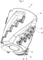
- An indexable rotary cutting tool 10 is basically constituted by: a substantially cylindrical tool body 20 having a plurality of insert seats 28; and a plurality of cutting inserts 30 mounted on the insert seats 28, as shown in Figs. 1 and 2 .
- the indexable rotary cutting tool 10 of the present embodiment is sometimes referred to as a roughing cutter.
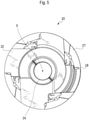
- the tool body 20 has a cylindrical shape including a substantially circular first end surface 21, a second end surface 22 arranged so as to oppose the first end surface 21 and having a substantially circular shape similarly to the first end surface 21, and a peripheral surface 23 connecting these end surfaces 21, 22.
- the tool body 20 has a rotational axis O passing through a center point of the first end surface 21 and a center point of the second end surface 22.
- the indexable rotary cutting tool 10 rotates with respect to the rotational axis O.
- the first end surface 21 is an end surface arranged at a proximal end of the tool body 20 and is also referred to as a proximal end surface.
- the proximal end of the tool body 20 refers to an end to be mounted on a machine tool.
- the second end surface 22 is an end surface arranged at a distal end of the tool body 20 and is also referred to as a distal end surface.
- the distal end of the tool body 20 refers to an end which is to be brought closer to a work piece.
- the tool body 20 is provided with a through hole 24 formed so as to extend from the first end surface 21 to the second end surface 22 along the rotational axis O and a plurality of coolant supply holes 25 through which coolant flows.
- An attachment bolt to be used for fixing the tool body 20 to an arbor in the machine tool is inserted into the through hole 24.
- the first end surface 21 is provided with an opening of the through hole 24, openings of the coolant supply holes 25, and a key groove 26 for transferring a motive force from the main shaft of the machine tool.
- the second end surface 22 is provided with an opening of the through hole 24 and notches resulting from the provision of the insert seats 28.
- a plurality of grooves 27 is formed in a spiral manner in the peripheral surface 23 between the first end surface 21 and the second end surface 22 of the tool body 20.
- the grooves 27 are formed so as to be twisted counterclockwise from the proximal end toward the distal end, as viewed from the distal end surface of the tool body 20.
- the grooves 27 start in the vicinity of the first end surface 21 of the tool body 20 and reach the second end surface 22.
- the number of grooves 27 is not limited thereto and any number of grooves may be provided, as long as there are one or more grooves.
- the plurality of insert seats 28 is formed in areas of the grooves 27 facing forward in the tool rotating direction.
- the number of insert seats 28 is not limited thereto and two or more insert seats 28 may be provided in one groove 27.
- a plurality of coolant ejection ports 29 for ejecting the coolant are provided in areas of the grooves 27 facing opposite to the tool rotating direction.
- the coolant ejection ports 29 communicate with the coolant supply holes 25.
- the number, arrangement, etc. of the coolant ejection ports 29 and the coolant supply holes 25 may be changed as appropriate, in accordance with a desired cooling performance, etc.
- the insert seat 28 located closest to the distal end of the tool is defined as a first segment
- the insert seat 28 next to the first segment is defined as a second segment
- the insert seat 28 next to the second segment is defined as a third segment
- the insert seat 28 next to the third segment is defined as a fourth segment
- the insert seat 28 closest to the proximal end is defined as a fifth segment (the uppermost segment).
- the insert seat 28 is basically constituted by a bottom surface 281 that is brought into contact with a lower surface (seating surface) 32 of the cutting insert 30 and two side surfaces 282 that are brought into contact with a peripheral surface (restraining surface) 33 of the cutting insert 30.
- the bottom surface 281 of the insert seat has a generally similar shape to the shape of the seating surface 32 of the cutting insert 30 to be attached thereto. Although the shape is substantially triangular in the present embodiment, the shape is not limited thereto.
- the bottom surface 281 is provided with a fixture hole 283 at substantially the center thereof for fixing the cutting insert 30 onto the insert seat 28 by, for example, screwing. Specifically, although the fixture hole 283 in Fig.
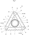
- the cutting insert 30 used in the present embodiment is basically constituted by: an upper surface 31 whose basic contour is a substantially regular triangle; a lower surface 32 arranged so as to oppose the upper surface 31 and having a substantially triangular shape; and a peripheral surface 33 connecting the upper surface 31 and the lower surface 32. More specifically, the cutting insert 30 has a shape in which a part near each vertex of the triangle is cut off by a line substantially orthogonal to one side of the triangle.
- the upper surface 31 has a hexagonal shape of 120 degrees rotational symmetry formed by alternately-intersecting long sides and short sides.
- An angle formed by the upper surface 31 and the peripheral surface 33 is an acute angle, while an angle formed by the lower surface 32 and the peripheral surface 33 is a blunt angle. Accordingly, this cutting insert 30 is a so-called positive type.
- the upper surface 31 functions as a rake surface
- the peripheral surface 33 functions as a flank or restraining surface
- the lower surface 32 functions as a seating surface.
- An attachment hole 36 is formed so as to penetrate substantially the center of the upper surface 31 and the lower surface 32.
- Part of intersecting edges between the upper surface 31 and the peripheral surface 33 is provided with cutting edges.
- major cutting edges 34 are formed on long side portions and minor cutting edges 35 are formed on short side portions.
- a corner cutting edge 37 is formed on each corner at which the long side portion and the short side portion intersect with each other substantially at a right angle. Accordingly, since the cutting insert 30 of the present embodiment has three sets of a major cutting edge 34, a minor cutting edge 35 and a corner cutting edge 37, by rotating the cutting insert by 120 degrees and attaching it onto the insert seat 28 to use every set of cutting edges, a single cutting insert 30 can perform cutting three times.
- the shape and configuration of the cutting insert 30 used for the indexable rotary cutting tool 10 according to the present invention are not limited thereto and may be changed as appropriate.
- the cutting insert 30 may be of a negative-type in which the peripheral surface 33 intersects with the upper surface 31 and the lower surface 32 at 90 degrees.
- both the upper surface and the lower surface are formed in a congruent shape and, if the lower surface 32 is also provided with cutting edges, then the cutting insert is able to perform cutting six times in total by inverting the upper surface and the lower surface.
- the basic contour of the cutting insert may be other polygonal shapes, such as quadrangles and pentagons.
- the major cutting edges 34 are formed in a wave shape.
- the "wave shape” as used herein refers to a shape formed by alternately connecting outwardly-curved cutting edge portions 341 that are curved like arcs toward the outside of the cutting insert 30 and inwardly-curved cutting edge portions 342 that are curved like arcs toward the inside of the cutting insert 30, in the top view of the cutting insert 30.
- all portions of the wave shape do not necessarily have to be arc-like curved portions and a part thereof may be formed linearly.
- the major cutting edge 34 is formed in a wave shape throughout its length and formed in a sine wave.
- a portion of the peripheral surface 33 that is adjacent to the wave-shape major cutting edge 34 is also formed in a wave shape corresponding to the wave shape of the major cutting edge 34.
- wave-shape cutting edge since only peak portions (the outwardly-curved cutting edge portions 341) are basically involved in cutting, chips are separated into small pieces.
- cutting resistance can be reduced.
- such cutting insert is suitable for a tool that forms large depth of cut and thereby discharges a large amount of chips and has a high cutting resistance, such as a roughing cutter.
- the major cutting edge 34, the corner cutting edge 37 and the minor cutting edge 35 along the respective sides of the triangle are connected in the order mentioned so as to form a set of cutting edges, as described above. Accordingly, a minor cutting edge 35 in a certain set is connected to another major cutting edge 34 in an adjacent set.
- a connecting part A1 between the minor cutting edge 35 in the certain set and the major cutting edge 34 in the adjacent set and a peripheral part of the connecting part A1 also function as an inner cutting edge 38.
- the “inner cutting edge” refers to a cutting edge that does not function in a normal lateral feeding (a feeding in a plane orthogonal to the axis of the tool) but is used when the tool is fed also in the axial direction of the tool, as in ramp cutting.
- a portion that is provided on a side opposite to the side to which the corner cutting edge 37 is connected serves as the inner cutting edge 38.
- a cutting edge portion that may serve as the inner cutting edge 38 is a cutting edge portion that extends from the connecting part A1 between the minor cutting edge 35 in a certain set and the major cutting edge 34 in the adjacent set by a certain length toward the major cutting edge 34, as shown in Fig. 7 .
- a part in the vicinity of an outwardly-curved cutting edge portion 351 located closest to an end (connecting part A1) also serves as the inner cutting edge.
- the outwardly-curved cutting edge portion 351 located closest to the end has a shape in which the position that is projected outermost in the top view is the connecting point A1 between the major cutting edge 34 and the minor cutting edge 35, i.e., a shape that ends at the highest point (the middle point of the peak).
- lands 39 are formed on all the cutting edges 34, 35 and 37, and the width and angle of these lands are not constant.
- the land width and the land angle are constant in areas extending from the center point C of the major cutting edge 34 and before reaching the ends (i.e., the connecting point A1 between the major cutting edge 34 and the minor cutting edge 35 of the adjacent set and a connecting point A2 between the major cutting edge 34 and the corner cutting edge 37 of the same set) of the major cutting edge 34.
- the land width is 0.15 mm and the land angle is 5°.
- the land width and the land angle vary in areas extending from points that are located slightly on the center point C side with respect to the respective connecting points A1, A2 to the connecting points A1, A2, in the major cutting edge 34. In such areas, the land width varies so as to become larger and the land angle varies so as to become smaller, from the center point C side toward the connecting points A1, A2. At the connecting points A1, A2, the land width becomes the largest and the land angle becomes the smallest. Specifically, at the connecting points A1, A2, the land width is 0.2 mm and the land angle is 0°.
- the land width and the land angle of the lands 39 in the corner cutting edge 37 and the minor cutting edge 35 are the same, throughout their lengths, as the land width and the land angle at the connecting points A1, A2 between such corner cutting edge 37 and minor cutting edge 35 and the major cutting edge 34. Accordingly, the land width is 0.2 mm and the land angle is 0° in the minor cutting edge 35 and the major cutting edge 34.
- Such cutting insert 30 is mounted on the insert seat 28 of the tool body 20 by a fastening screw 40. At this time, the lower surface 32 of the cutting insert 30 is brought into contact with the bottom surface 281 of the insert seat 28. In addition, the peripheral surfaces 33 of the cutting insert 30 are brought into contact with the side surfaces 282 of the insert seat 28. At this time, the cutting insert 30 is mounted so as to be arranged in positional relationships in which the major cutting edge 34 is parallel to the peripheral surface 23 of the tool body 20 on the peripheral surface 23 side and the minor cutting edge 35 is parallel to a distal end surface of the tool body 20 on the distal end surface side, as shown in Fig. 2 . A wedge, a presser piece, etc.
- the attachment hole 36 can be used, other than the fastening screw 40, to fix the cutting insert 30.
- the attachment hole 36 by forming the attachment hole 36 so that the diameter of its end parts is larger than that of its central part and bringing a head part of the fastening screw 40 into contact with stepped portions formed by such larger diameter parts of the attachment hole to thereby fix the cutting insert 30 to the tool body 20, it is possible to eliminate projections projected in the groove 27. Thus, the discharging efficiency of chips can be enhanced.
- the cutting edges 34, 35, 37 of the cutting insert 30 can be made of hard materials, such as a cemented carbide, cermet, ceramic, a material obtained by applying some coating to these materials, an ultrahigh-pressure sintered body containing diamond or cubic boron nitride, and a material obtained by applying some coating to the ultrahigh-pressure sintered body containing cubic boron nitride.
- the remaining parts other than the cutting edges 34, 35, 37 of the cutting insert 30 are preferably made of similarly hard materials.
- five cutting inserts 30 are mounted per one groove 27.
- the major cutting edge 34 thereof is involved in cutting of a side surface of a work piece
- the minor cutting edge 35 thereof is involved in cutting of a bottom surface of the work piece
- the corner cutting edge 37 thereof is involved in cutting of a corner of the work piece.
- the minor cutting edges 35 and the corner cutting edges 37 are not involved in cutting of the work piece, although the major cutting edges 34 thereof are involved in cutting of the side surface of the work piece.
- the minor cutting edges 35 and the corner cutting edges 37 of the second to fifth segment cutting inserts 30 are arranged so as not to be projected with respect to the rotational trajectories of the major cutting edges 34 of the corresponding cutting inserts 30 in the other grooves.
- the cutting inserts 30 are arranged in an overlapped manner in one groove 27 in the direction of the rotational axis O in the side view of the tool body 20. More specifically, the major cutting edges 34 of adjacent cutting inserts 30 in one groove are arranged such that their cutting portions are overlapped in the direction of the rotational axis O. Since the insert seats 28 are formed in a stair-like shape in the spiral groove 27 as shown in Fig. 2 , such overlapped arrangement of the cutting inserts 30 can be achieved.
- the cutting inserts 30 are arranged so as to be partially overlapped in the direction of the rotational axis O in one groove 27, as described above. More specifically, the cutting inserts 30 have the following characteristic configurations.
- Fig. 8 shows a state in which rotational trajectories 301-305 of five cutting inserts, i.e., from the cutting insert located closest to the distal end to the cutting insert located closest to the proximal end, are projected at a certain angular position in the tool rotating direction. As shown in Fig.
- the cutting inserts 30 are arranged so as to be overlapped in the direction of the rotational axis O such that the phases of the waves of the rotational trajectories 301-305 formed by the adjacent cutting inserts 30 coincide with each other.
- the cutting inserts 30 are arranged such that the waves of the rotational trajectories formed by the major cutting edges 34 of the cutting inserts 30 are formed continuously between the adjacent cutting inserts 30.
- the cutting inserts 30 are arranged such that, in the rotational trajectories formed by the major cutting edges 34 (the rotational trajectories 302 and 303 formed by the second segment cutting insert and the third segment cutting insert, respectively in Fig. 9 ) only the rotational trajectories formed by the respective outwardly-curved cutting edge portions 341 located closest to the ends of the major cutting edge 34 are overlapped in the direction of the rotational axis O, in each groove 27.
- This relates to, more precisely, the relationship between the rotational trajectory of the outwardly-curved cutting edge portion 351 of a cutting insert located relatively closer to the distal end and the rotational trajectory of the outwardly-curved cutting edge portion 341 connected to the corner cutting edge of a cutting insert located relatively closer to the proximal end.
- the same relationship is applied to all the adjacent cutting inserts 30 in all the grooves 27.
- the cutting inserts 30 are arranged in such a way that the phases of the waves of the rotational trajectories of the cutting tool 10 are shifted in the direction of the rotational axis O of the tool, so that the phases of the waves of the rotational trajectories of the grooves 27 do not coincide with each other when the rotational trajectories of all the grooves 27 are superimposed.
- Fig. 10 which shows portion X in Fig.
- the configurations in which the phases of the wave-like rotational trajectories of the adjacent cutting inserts 30 coincide with each other and the rotational trajectories formed by part of the cutting edge portions are overlapped indicate that at least the outwardly-curved cutting edge portions 341 located closest to an end (the connecting point A1) of the major cutting edges 34 are overlapped in the circumferential direction in the present embodiment.
- the outwardly-curved cutting edge portion 351 of the major cutting edge 34 can also serve as the inner cutting edge 38.
- outwardly-curved cutting edge portion 351 is used for cutting twice, i.e., the cutting of the side surface and the cutting of the bottom surface of a work piece.
- the outwardly-curved cutting edge portion 351 is used as the major cutting edge 34 and is also used as the inner cutting edge 38.
- the outwardly-curved cutting edge portion 351 is subjected to quite a large load and is prone to breakage.
- such problems can be suppressed. This is because, in an area corresponding to the outwardly-curved cutting edge portion 351 in the rotating direction, there are twice as many cutting edges as in the other cutting edge portions.
- an area in the vicinity of the outwardly-cutting edge portion 351 is overlapped with an area in the vicinity of the outwardly-curved cutting edge portion 341 at an end of the adjacent cutting insert and, further, since the tool body 20 is provided with four grooves, from among the major cutting edges 34, four cutting edges are used for cutting in areas corresponding to the other cutting edge portions in the rotating direction whereas eight cutting edges are used for cutting in the area corresponding to the overlapped outwardly-curved cutting edge portions 351 in the rotating direction. Accordingly, since the thickness of cut per cutting edge is small in such area, the cutting load can be greatly reduced. As described above, by greatly reducing the load applied to the outwardly-curved cutting edge portions 341 that are used for cutting twice, it is possible to significantly suppress fracture in such portion that is used also as the inner edge 38.
- the cutting inserts 30 are arranged so as to be overlapped in the direction of the rotational axis O such that only the rotational trajectories formed by the outwardly-curved cutting edge portions 341 located closest to the end of the major cutting edges 34 (i.e., the outwardly-curved cutting edge portion 351 corresponding to the inner cutting edge 38 of a cutting insert located relatively closer to the distal end and the outwardly-curved cutting edge portion 341 connected to the corner cutting edge of a cutting insert located relatively closer to the proximal end) coincide with each other, from among the rotational trajectories formed by the major cutting edges 34.
- the arrangement is not limited thereto.
- the cutting inserts 30 may be arranged such that the rotational trajectories formed by more than one outwardly-curved cutting edge 341 from the end are overlapped with each other.
- the arrangement in which only the portions located closest to the end are overlapped is preferable.
- the arrangement is not limited thereto. Specifically, the effect of suppressing fracture in the outwardly-curved cutting edge portions 351 can be achieved to some extent even by a configuration in which only some of the adjacent inserts 30 in some of the grooves 27 are overlapped with each other. However, in order to maximize the fracture suppressing effect, the arrangement in which all the adjacent cutting inserts 30 are overlapped with each other in all the grooves 27 is preferable.
- the cutting insert 30 whose outwardly-curved cutting edge portion 351 serves as the inner cutting edge 38 is only the cutting insert located closest to the distal end. This is because, when all the cutting inserts in the tool are replaced at the same time, the cutting insert that has been located closest to the distal end is replaced with the cutting insert that has been located closest to the proximal end for use.
- the cutting inserts 30 are arranged such that the phases of the waves of the rotational trajectories are shifted in the direction of the tool rotational axis O and such that, when the rotational trajectories of all the grooves 27 are superimposed, the phases of the waves of the rotational trajectories of such grooves 27 do not coincide with each other.
- the height difference between the peak portions and valley portions of the wave-like rotational trajectories of the major cutting edges 34 is reduced when all the grooves 27 are superimposed, the amount of portions that remain uncut due to the valley portions can be reduced and the surface roughness of a worked surface of a work piece can be enhanced.
- the lands 39 are formed in all of the major cutting edges 34, the minor cutting edges 35 and the corner cutting edge 37 in the cutting inserts 30 and the land width at the connecting point A1 between the major cutting edge 34 and the minor cutting edge 35 is larger than the land width at the center point C of the major cutting edge 34 while the land angle at the connecting point A1 is smaller than the land angle at the center point C.
- an area corresponding to the inner cutting edge 38 of the cutting insert 30 located closest to the distal end of the tool contains one cutting edge
- an area corresponding to the inner cutting edge 38 of the cutting insert 30 located second closest to the distal end contains two cutting edges
- an area corresponding to the inner cutting edge 38 of the cutting insert 30 located third closest to the distal end contains three cutting edges. Accordingly, cutting resistances applied to these inner cutting edges 38 are larger than the cutting resistance applied to the normal inner cutting edge, i.e., an area corresponding to the inner cutting edge 38 of the cutting insert 30 located fourth closest to the distal end of the tool and containing four cutting edges, and thus, the configuration of strengthening the lands as described above is effective.
- the lands 39 are kept sharp, so that the cutting performance can be maintained.
- the land width and land angle of the minor cutting edge 35 are preferably equal to the land width and land angle at the connecting point A1.
- Such configuration can enhance the strength of the minor cutting edge 35 to which a large load is applied in the configuration in which the grooves 27 are arranged such that the phases of the waves of their rotational trajectories are shifted from each other in the direction of axis O of the tool, as described above.
- the shape of the cutting inserts 30 used in the present invention does not have to be limited to the triangular shape in plan view. In other words, other shapes may be employed, as long as the cutting insert 30 has the configuration in which part of the major cutting edge 34 is also used as the inner cutting edge 38.
Claims (6)
- Outil de coupe rotatif amovible (10) comprenant : un corps d'outil sensiblement cylindrique (20) ayant un axe de rotation (O) ; et des plaquettes de coupe (30) montées sur le corps d'outil (20), dans lesquelles une pluralité de rainures (27) est formée sur une surface périphérique (23) du corps d'outil (20), une pluralité de sièges de plaquette (28) est formée dans les rainures (27), et les plaquettes de coupe (30) sont agencées de manière amovible sur les sièges de plaquette (28), où :les plaquettes de coupe (30) ont chacune une surface de dépouille (31) et un flanc (33) croisant la surface de dépouille (31), et une arête de coupe principale (34), une arête de coupe de coin (37) reliée à l'arête de coupe principale (34), et une arête de coupe secondaire (35) reliée à l'arête de coupe de coin (37), sont formées dans un bord d'intersection entre la surface de dépouille (31) et le flanc (33) ;l'arête de coupe principale (34) est formée le long de chaque côté de la surface de dépouille (31) de la plaquette de coupe (30) et a une forme ondulée vue depuis une direction faisant face à la surface de dépouille (31) etles plaquettes de coupe (30) sont agencées de telle sorte que, dans des trajectoires de rotation formées par les arêtes de coupe principales (34) des plaquettes de coupe respectives (30) lorsque l'outil de coupe rotatif amovible (10) est amené à tourner autour de l'axe de rotation (O), les phases des ondulations de trajectoires de rotation formées par les plaquettes de coupe (30) qui sont adjacentes les unes aux autres dans une direction le long de l'axe de rotation (O) dans une rainure (27) coïncident les unes avec les autres, et de telle sorte qu'au moins certaines des plaquettes de coupe (30) sont agencées de telle sorte que, parmi les trajectoires de rotation formées par les arêtes de coupe principales (34), des trajectoires de rotation formées par une partie des parties d'arête de coupe se chevauchent les unes les autres dans une direction de l'axe de rotation (O), oùl'arête de coupe principale (34) est formé en une forme ondulée ayant une pluralité de parties d'arête de coupe courbées vers l'extérieur (341) qui sont courbées vers l'extérieur lorsqu'elles sont vues depuis la direction faisant face à la surface de dépouille (31) ; etcaractérisé en ce quedans chacune des rainures (27), les au moins certaines plaquettes de coupe (30) sont agencées de telle sorte que, parmi les trajectoires de rotation formées par les arêtes de coupe principales (34), seules les trajectoires de rotation formées par des parties d'arête de coupe courbées vers l'extérieur (341) situées le plus près des extrémités des arêtes de coupe principales (34) se chevauchent les unes les autres dans la direction de l'axe de rotation (O) et, où :
dans la pluralité de parties d'arête de coupe courbées vers l'extérieur (341), une partie d'arête de coupe courbée vers l'extérieur (351) située à une extrémité de l'arête de coupe principale (34) et reliée à l'arête de coupe secondaire (35) est configurée pour servir également d'arête de coupe interne (38). - Outil de coupe rotatif amovible (10) selon la revendication 1, où, dans toutes les rainures (27), toutes les plaquettes de coupe adjacentes (30) sont agencées de telle sorte que les trajectoires de rotation des extrémités se chevauchent les unes les autres dans la direction de l'axe de rotation (O).
- Outil de coupe rotatif amovible (10) selon l'une quelconque des revendications 1 ou 2, où, dans une relation entre les trajectoires de rotation des plaquettes de coupe agencées dans des rainures (27) qui sont adjacentes les unes aux autres dans une direction circonférentielle du corps d'outil (20), les plaquettes de coupe (30) sont agencées de telle sorte que les phases des ondulations des trajectoires de rotation sont décalées les unes des autres dans la direction de l'axe de rotation (O), et lorsque les trajectoires de rotation de toutes les rainures (27) sont superposées, les phases des ondulations des trajectoires de rotation des rainures (27) ne coïncident pas les unes avec les autres.
- Outil de coupe rotatif amovible (10) selon l'une quelconque des revendications 1 à 3, où :l'arête de coupe secondaire (35) de la plaquette de coupe (30) est reliée à une arête de coupe principale (34) différente de ladite arête de coupe principale (34) ;des sillons (39) sont formés dans l'ensemble de l'arête de coupe principale (34), de l'arête de coupe secondaire (35) et de l'arête de coupe de coin (37) ;une largeur de sillon au niveau d'un point de connexion (A1) entre ladite arête de coupe principale différente (34) et l'arête de coupe secondaire (35) est plus grande qu'une largeur de sillon au niveau d'un point central (C) dans l'arête de coupe principale différente (34) ; etun angle de sillon au point de connexion (A1) entre l'arête de coupe principale différente (34) et l'arête de coupe secondaire (35) est plus petit qu'un angle de sillon au point central (C) dans l'arête de coupe principale différente (34).
- Outil de coupe rotatif amovible (10) selon la revendication 4, dans lequel une largeur de sillon et un angle de sillon de l'arête de coupe secondaire (35) sont égaux à la largeur de sillon et à l'angle de sillon au niveau du point de connexion (A1).
- Outil de coupe rotatif amovible (10) selon l'une quelconque des revendications 1 à 5, où les plaquettes de coupe (30) ont une forme sensiblement triangulaire vue depuis une direction faisant face à la surface de dépouille (31).
Applications Claiming Priority (2)
| Application Number | Priority Date | Filing Date | Title |
|---|---|---|---|
| JP2014143780 | 2014-07-14 | ||
| PCT/JP2015/070057 WO2016009995A1 (fr) | 2014-07-14 | 2015-07-13 | Outil de coupe rotatif de type à arêtes remplaçables |
Publications (3)
| Publication Number | Publication Date |
|---|---|
| EP3147057A1 EP3147057A1 (fr) | 2017-03-29 |
| EP3147057A4 EP3147057A4 (fr) | 2017-09-13 |
| EP3147057B1 true EP3147057B1 (fr) | 2022-03-02 |
Family
ID=55078487
Family Applications (1)
| Application Number | Title | Priority Date | Filing Date |
|---|---|---|---|
| EP15821813.1A Active EP3147057B1 (fr) | 2014-07-14 | 2015-07-13 | Outil de coupe rotatif indexable |
Country Status (5)
| Country | Link |
|---|---|
| US (1) | US10124423B2 (fr) |
| EP (1) | EP3147057B1 (fr) |
| JP (1) | JP6011831B2 (fr) |
| CN (1) | CN105813785B (fr) |
| WO (1) | WO2016009995A1 (fr) |
Families Citing this family (6)
| Publication number | Priority date | Publication date | Assignee | Title |
|---|---|---|---|---|
| US10556278B2 (en) * | 2016-08-16 | 2020-02-11 | Kennametal Inc. | Tool body for a shell end mill and cutting tool |
| CN106862618B (zh) * | 2016-12-30 | 2019-12-13 | 株洲钻石切削刀具股份有限公司 | 钻削加工刀具 |
| CN106825719B (zh) * | 2016-12-30 | 2019-12-06 | 株洲钻石切削刀具股份有限公司 | 切削刀片 |
| CN107234285B (zh) * | 2017-05-17 | 2020-07-17 | 贺州学院 | 一种成型铣刀及其制造方法 |
| CN112108697A (zh) | 2019-06-20 | 2020-12-22 | 肯纳金属印度有限公司 | 具有容纳间隙角不同的切割插入件的凹穴的工具固持器 |
| US11806796B2 (en) * | 2021-03-15 | 2023-11-07 | Kennametal Inc. | Cutting insert and cutting tool comprising cutting insert |
Family Cites Families (19)
| Publication number | Priority date | Publication date | Assignee | Title |
|---|---|---|---|---|
| US4936719A (en) | 1976-08-24 | 1990-06-26 | Greenleaf Corporation | Cutter and indexable on edge inserts with aligned corners and staggered serrated edges |
| JPH0135777Y2 (fr) * | 1985-05-25 | 1989-11-01 | ||
| US4844666A (en) * | 1986-08-22 | 1989-07-04 | Izumo Industrial Co., Ltd. | Insert rotary cutting tool |
| CA1270631A (fr) * | 1987-02-06 | 1990-06-26 | Robert Theodore Koblesky | Mises de coupe a ajustage reciproque sur rives pour outils de fraisage |
| CA2062213C (fr) * | 1992-03-03 | 1996-07-16 | Alfonso Minicozzi | Plaquette amovible pour outils de deroulage |
| US5542792A (en) * | 1993-12-21 | 1996-08-06 | Waukesha Cutting Tools, Inc. | Cutting device with removable nosepiece |
| JPH0839308A (ja) * | 1994-07-26 | 1996-02-13 | Mitsubishi Materials Corp | スローアウェイチップ |
| IL119114A0 (en) * | 1996-08-22 | 1996-11-14 | Iscar Ltd | Cutting insert |
| US5913644A (en) * | 1998-04-20 | 1999-06-22 | Kennametal Inc. | Helical mill having multiple flutes with differing rake angles |
| DE10043015C2 (de) * | 2000-09-01 | 2002-09-19 | Walter Ag | Zerspanungswerkzeug mit direkter Schneidplattenanlage |
| US6811359B2 (en) * | 2002-05-31 | 2004-11-02 | Kennametal Inc. | True helical cutter system |
| US7563059B2 (en) * | 2006-04-21 | 2009-07-21 | Yg-1 Co., Ltd. | Sinusoidal angled rotary cutting tool |
| JP5023628B2 (ja) * | 2006-09-13 | 2012-09-12 | 三菱マテリアル株式会社 | ラフィングエンドミル |
| EP2060353B1 (fr) * | 2006-09-13 | 2012-12-19 | Mitsubishi Materials Corporation | Plaquette de dégrossissage, et fraise en bout de dégrossissage |
| US8613574B2 (en) * | 2008-02-22 | 2013-12-24 | Kennametal Inc. | Helical milling cutter |
| CN102341203B (zh) * | 2009-03-06 | 2015-04-29 | 三菱综合材料株式会社 | 切削刀片及刀片可拆装式切削工具 |
| KR101097658B1 (ko) * | 2009-05-29 | 2011-12-22 | 대구텍 유한회사 | 절삭 삽입체 |
| JP2013202770A (ja) * | 2012-03-29 | 2013-10-07 | Mitsubishi Materials Corp | 刃先交換式エンドミル及びこれに用いるエンドミル本体 |
| US9505066B2 (en) * | 2014-08-01 | 2016-11-29 | Kennametal Inc. | Rotary cutting tool with regrindable cutting inserts |
-
2015
- 2015-07-13 EP EP15821813.1A patent/EP3147057B1/fr active Active
- 2015-07-13 US US15/312,755 patent/US10124423B2/en active Active
- 2015-07-13 CN CN201580003184.XA patent/CN105813785B/zh active Active
- 2015-07-13 JP JP2015543211A patent/JP6011831B2/ja active Active
- 2015-07-13 WO PCT/JP2015/070057 patent/WO2016009995A1/fr active Application Filing
Also Published As
| Publication number | Publication date |
|---|---|
| JP6011831B2 (ja) | 2016-10-19 |
| JPWO2016009995A1 (ja) | 2017-04-27 |
| US10124423B2 (en) | 2018-11-13 |
| CN105813785A (zh) | 2016-07-27 |
| CN105813785B (zh) | 2017-08-18 |
| WO2016009995A1 (fr) | 2016-01-21 |
| US20170189974A1 (en) | 2017-07-06 |
| EP3147057A4 (fr) | 2017-09-13 |
| EP3147057A1 (fr) | 2017-03-29 |
Similar Documents
| Publication | Publication Date | Title |
|---|---|---|
| EP3147057B1 (fr) | Outil de coupe rotatif indexable | |
| JP6532940B2 (ja) | 両面型切削インサートおよびフライス工具 | |
| JP5023628B2 (ja) | ラフィングエンドミル | |
| US5145294A (en) | Milling cutter capable of using indexable inserts of various shapes | |
| EP3266547B1 (fr) | Insert de coupe, et outil de coupe rotatif à bord de coupe remplaçable | |
| US20200368830A1 (en) | Indexable rotary cutting tool and tool body | |
| EP3175945B1 (fr) | Plaquette de coupe et outil de coupe à bord de coupe remplaçable | |
| EP2489454A1 (fr) | Plaquette de coupe et outil tournant avec arête de lame interchangeable | |
| WO2017122715A1 (fr) | Plaquette de coupe et outil de coupe à pointe de coupe remplaçable | |
| JP6436093B2 (ja) | 切削インサート及び刃先交換式切削工具 | |
| KR20140106538A (ko) | 절삭 인서트 및 날끝 교환식 절삭 공구 | |
| JP7098538B2 (ja) | 表および裏面取り用回転式フライスのための星形切削インサート | |
| JP2008229744A (ja) | 切削インサートおよびインサート着脱式転削工具 | |
| JP6361948B2 (ja) | 切削インサートおよび切削工具 | |
| JP2014136264A (ja) | 正面フライス用切削インサート及び刃先交換式正面フライス | |
| EP3112067B1 (fr) | Outil de coupe rotatif avec plaquettes de coupe indexables | |
| JP7101679B2 (ja) | 切削インサートおよび肩削りフライス工具 | |
| WO2014021314A1 (fr) | Plaquette de coupe, et outil de coupe à tranchant d'arête remplaçable | |
| EP3233340B1 (fr) | Outil de coupe ayant un nombre prédéterminé de cannelures hélicoïdales à gauche et à droite et de dents de coupe à la face terminale | |
| JP5483872B2 (ja) | 切削インサートおよび切削工具ならびにそれらを用いた切削方法 | |
| CN104439460A (zh) | 一种粗加工可转位立铣刀 | |
| JP6004301B2 (ja) | 切削インサート及び刃先交換式回転切削工具 | |
| JP6318558B2 (ja) | 切削インサートおよび刃先交換式穴加工工具 | |
| CN117206606A (zh) | 螺纹铣刀 | |
| JPH04130115U (ja) | スローアウエイ式エンドミル |
Legal Events
| Date | Code | Title | Description |
|---|---|---|---|
| PUAI | Public reference made under article 153(3) epc to a published international application that has entered the european phase |
Free format text: ORIGINAL CODE: 0009012 |
|
| STAA | Information on the status of an ep patent application or granted ep patent |
Free format text: STATUS: REQUEST FOR EXAMINATION WAS MADE |
|
| 17P | Request for examination filed |
Effective date: 20160701 |
|
| AK | Designated contracting states |
Kind code of ref document: A1 Designated state(s): AL AT BE BG CH CY CZ DE DK EE ES FI FR GB GR HR HU IE IS IT LI LT LU LV MC MK MT NL NO PL PT RO RS SE SI SK SM TR |
|
| AX | Request for extension of the european patent |
Extension state: BA ME |
|
| A4 | Supplementary search report drawn up and despatched |
Effective date: 20170810 |
|
| RIC1 | Information provided on ipc code assigned before grant |
Ipc: B23C 5/20 20060101ALI20170804BHEP Ipc: B23C 5/10 20060101AFI20170804BHEP |
|
| DAV | Request for validation of the european patent (deleted) | ||
| DAX | Request for extension of the european patent (deleted) | ||
| GRAP | Despatch of communication of intention to grant a patent |
Free format text: ORIGINAL CODE: EPIDOSNIGR1 |
|
| STAA | Information on the status of an ep patent application or granted ep patent |
Free format text: STATUS: GRANT OF PATENT IS INTENDED |
|
| INTG | Intention to grant announced |
Effective date: 20210922 |
|
| GRAS | Grant fee paid |
Free format text: ORIGINAL CODE: EPIDOSNIGR3 |
|
| GRAA | (expected) grant |
Free format text: ORIGINAL CODE: 0009210 |
|
| STAA | Information on the status of an ep patent application or granted ep patent |
Free format text: STATUS: THE PATENT HAS BEEN GRANTED |
|
| AK | Designated contracting states |
Kind code of ref document: B1 Designated state(s): AL AT BE BG CH CY CZ DE DK EE ES FI FR GB GR HR HU IE IS IT LI LT LU LV MC MK MT NL NO PL PT RO RS SE SI SK SM TR |
|
| REG | Reference to a national code |
Ref country code: GB Ref legal event code: FG4D |
|
| REG | Reference to a national code |
Ref country code: CH Ref legal event code: EP Ref country code: AT Ref legal event code: REF Ref document number: 1471852 Country of ref document: AT Kind code of ref document: T Effective date: 20220315 |
|
| REG | Reference to a national code |
Ref country code: DE Ref legal event code: R096 Ref document number: 602015077285 Country of ref document: DE |
|
| REG | Reference to a national code |
Ref country code: IE Ref legal event code: FG4D |
|
| REG | Reference to a national code |
Ref country code: LT Ref legal event code: MG9D |
|
| REG | Reference to a national code |
Ref country code: NL Ref legal event code: MP Effective date: 20220302 |
|
| PG25 | Lapsed in a contracting state [announced via postgrant information from national office to epo] |
Ref country code: SE Free format text: LAPSE BECAUSE OF FAILURE TO SUBMIT A TRANSLATION OF THE DESCRIPTION OR TO PAY THE FEE WITHIN THE PRESCRIBED TIME-LIMIT Effective date: 20220302 Ref country code: RS Free format text: LAPSE BECAUSE OF FAILURE TO SUBMIT A TRANSLATION OF THE DESCRIPTION OR TO PAY THE FEE WITHIN THE PRESCRIBED TIME-LIMIT Effective date: 20220302 Ref country code: NO Free format text: LAPSE BECAUSE OF FAILURE TO SUBMIT A TRANSLATION OF THE DESCRIPTION OR TO PAY THE FEE WITHIN THE PRESCRIBED TIME-LIMIT Effective date: 20220602 Ref country code: LT Free format text: LAPSE BECAUSE OF FAILURE TO SUBMIT A TRANSLATION OF THE DESCRIPTION OR TO PAY THE FEE WITHIN THE PRESCRIBED TIME-LIMIT Effective date: 20220302 Ref country code: HR Free format text: LAPSE BECAUSE OF FAILURE TO SUBMIT A TRANSLATION OF THE DESCRIPTION OR TO PAY THE FEE WITHIN THE PRESCRIBED TIME-LIMIT Effective date: 20220302 Ref country code: ES Free format text: LAPSE BECAUSE OF FAILURE TO SUBMIT A TRANSLATION OF THE DESCRIPTION OR TO PAY THE FEE WITHIN THE PRESCRIBED TIME-LIMIT Effective date: 20220302 Ref country code: BG Free format text: LAPSE BECAUSE OF FAILURE TO SUBMIT A TRANSLATION OF THE DESCRIPTION OR TO PAY THE FEE WITHIN THE PRESCRIBED TIME-LIMIT Effective date: 20220602 |
|
| REG | Reference to a national code |
Ref country code: AT Ref legal event code: MK05 Ref document number: 1471852 Country of ref document: AT Kind code of ref document: T Effective date: 20220302 |
|
| PG25 | Lapsed in a contracting state [announced via postgrant information from national office to epo] |
Ref country code: PL Free format text: LAPSE BECAUSE OF FAILURE TO SUBMIT A TRANSLATION OF THE DESCRIPTION OR TO PAY THE FEE WITHIN THE PRESCRIBED TIME-LIMIT Effective date: 20220302 Ref country code: LV Free format text: LAPSE BECAUSE OF FAILURE TO SUBMIT A TRANSLATION OF THE DESCRIPTION OR TO PAY THE FEE WITHIN THE PRESCRIBED TIME-LIMIT Effective date: 20220302 Ref country code: GR Free format text: LAPSE BECAUSE OF FAILURE TO SUBMIT A TRANSLATION OF THE DESCRIPTION OR TO PAY THE FEE WITHIN THE PRESCRIBED TIME-LIMIT Effective date: 20220603 Ref country code: FI Free format text: LAPSE BECAUSE OF FAILURE TO SUBMIT A TRANSLATION OF THE DESCRIPTION OR TO PAY THE FEE WITHIN THE PRESCRIBED TIME-LIMIT Effective date: 20220302 |
|
| PG25 | Lapsed in a contracting state [announced via postgrant information from national office to epo] |
Ref country code: NL Free format text: LAPSE BECAUSE OF FAILURE TO SUBMIT A TRANSLATION OF THE DESCRIPTION OR TO PAY THE FEE WITHIN THE PRESCRIBED TIME-LIMIT Effective date: 20220302 |
|
| PG25 | Lapsed in a contracting state [announced via postgrant information from national office to epo] |
Ref country code: SM Free format text: LAPSE BECAUSE OF FAILURE TO SUBMIT A TRANSLATION OF THE DESCRIPTION OR TO PAY THE FEE WITHIN THE PRESCRIBED TIME-LIMIT Effective date: 20220302 Ref country code: SK Free format text: LAPSE BECAUSE OF FAILURE TO SUBMIT A TRANSLATION OF THE DESCRIPTION OR TO PAY THE FEE WITHIN THE PRESCRIBED TIME-LIMIT Effective date: 20220302 Ref country code: RO Free format text: LAPSE BECAUSE OF FAILURE TO SUBMIT A TRANSLATION OF THE DESCRIPTION OR TO PAY THE FEE WITHIN THE PRESCRIBED TIME-LIMIT Effective date: 20220302 Ref country code: PT Free format text: LAPSE BECAUSE OF FAILURE TO SUBMIT A TRANSLATION OF THE DESCRIPTION OR TO PAY THE FEE WITHIN THE PRESCRIBED TIME-LIMIT Effective date: 20220704 Ref country code: EE Free format text: LAPSE BECAUSE OF FAILURE TO SUBMIT A TRANSLATION OF THE DESCRIPTION OR TO PAY THE FEE WITHIN THE PRESCRIBED TIME-LIMIT Effective date: 20220302 Ref country code: CZ Free format text: LAPSE BECAUSE OF FAILURE TO SUBMIT A TRANSLATION OF THE DESCRIPTION OR TO PAY THE FEE WITHIN THE PRESCRIBED TIME-LIMIT Effective date: 20220302 Ref country code: AT Free format text: LAPSE BECAUSE OF FAILURE TO SUBMIT A TRANSLATION OF THE DESCRIPTION OR TO PAY THE FEE WITHIN THE PRESCRIBED TIME-LIMIT Effective date: 20220302 |
|
| PG25 | Lapsed in a contracting state [announced via postgrant information from national office to epo] |
Ref country code: IS Free format text: LAPSE BECAUSE OF FAILURE TO SUBMIT A TRANSLATION OF THE DESCRIPTION OR TO PAY THE FEE WITHIN THE PRESCRIBED TIME-LIMIT Effective date: 20220702 Ref country code: AL Free format text: LAPSE BECAUSE OF FAILURE TO SUBMIT A TRANSLATION OF THE DESCRIPTION OR TO PAY THE FEE WITHIN THE PRESCRIBED TIME-LIMIT Effective date: 20220302 |
|
| REG | Reference to a national code |
Ref country code: DE Ref legal event code: R097 Ref document number: 602015077285 Country of ref document: DE |
|
| PLBE | No opposition filed within time limit |
Free format text: ORIGINAL CODE: 0009261 |
|
| STAA | Information on the status of an ep patent application or granted ep patent |
Free format text: STATUS: NO OPPOSITION FILED WITHIN TIME LIMIT |
|
| PG25 | Lapsed in a contracting state [announced via postgrant information from national office to epo] |
Ref country code: DK Free format text: LAPSE BECAUSE OF FAILURE TO SUBMIT A TRANSLATION OF THE DESCRIPTION OR TO PAY THE FEE WITHIN THE PRESCRIBED TIME-LIMIT Effective date: 20220302 |
|
| 26N | No opposition filed |
Effective date: 20221205 |
|
| PG25 | Lapsed in a contracting state [announced via postgrant information from national office to epo] |
Ref country code: SI Free format text: LAPSE BECAUSE OF FAILURE TO SUBMIT A TRANSLATION OF THE DESCRIPTION OR TO PAY THE FEE WITHIN THE PRESCRIBED TIME-LIMIT Effective date: 20220302 Ref country code: MC Free format text: LAPSE BECAUSE OF FAILURE TO SUBMIT A TRANSLATION OF THE DESCRIPTION OR TO PAY THE FEE WITHIN THE PRESCRIBED TIME-LIMIT Effective date: 20220302 |
|
| REG | Reference to a national code |
Ref country code: CH Ref legal event code: PL |
|
| GBPC | Gb: european patent ceased through non-payment of renewal fee |
Effective date: 20220713 |
|
| REG | Reference to a national code |
Ref country code: BE Ref legal event code: MM Effective date: 20220731 |
|
| PG25 | Lapsed in a contracting state [announced via postgrant information from national office to epo] |
Ref country code: LU Free format text: LAPSE BECAUSE OF NON-PAYMENT OF DUE FEES Effective date: 20220713 Ref country code: LI Free format text: LAPSE BECAUSE OF NON-PAYMENT OF DUE FEES Effective date: 20220731 Ref country code: FR Free format text: LAPSE BECAUSE OF NON-PAYMENT OF DUE FEES Effective date: 20220731 Ref country code: CH Free format text: LAPSE BECAUSE OF NON-PAYMENT OF DUE FEES Effective date: 20220731 |
|
| PG25 | Lapsed in a contracting state [announced via postgrant information from national office to epo] |
Ref country code: GB Free format text: LAPSE BECAUSE OF NON-PAYMENT OF DUE FEES Effective date: 20220713 Ref country code: BE Free format text: LAPSE BECAUSE OF NON-PAYMENT OF DUE FEES Effective date: 20220731 |
|
| PG25 | Lapsed in a contracting state [announced via postgrant information from national office to epo] |
Ref country code: IT Free format text: LAPSE BECAUSE OF FAILURE TO SUBMIT A TRANSLATION OF THE DESCRIPTION OR TO PAY THE FEE WITHIN THE PRESCRIBED TIME-LIMIT Effective date: 20220302 Ref country code: IE Free format text: LAPSE BECAUSE OF NON-PAYMENT OF DUE FEES Effective date: 20220713 |
|
| PGFP | Annual fee paid to national office [announced via postgrant information from national office to epo] |
Ref country code: DE Payment date: 20230719 Year of fee payment: 9 |
|
| PG25 | Lapsed in a contracting state [announced via postgrant information from national office to epo] |
Ref country code: HU Free format text: LAPSE BECAUSE OF FAILURE TO SUBMIT A TRANSLATION OF THE DESCRIPTION OR TO PAY THE FEE WITHIN THE PRESCRIBED TIME-LIMIT; INVALID AB INITIO Effective date: 20150713 |
|
| PG25 | Lapsed in a contracting state [announced via postgrant information from national office to epo] |
Ref country code: MK Free format text: LAPSE BECAUSE OF FAILURE TO SUBMIT A TRANSLATION OF THE DESCRIPTION OR TO PAY THE FEE WITHIN THE PRESCRIBED TIME-LIMIT Effective date: 20220302 Ref country code: CY Free format text: LAPSE BECAUSE OF FAILURE TO SUBMIT A TRANSLATION OF THE DESCRIPTION OR TO PAY THE FEE WITHIN THE PRESCRIBED TIME-LIMIT Effective date: 20220302 |