EP3147057B1 - Indexable rotary cutting tool - Google Patents
Indexable rotary cutting tool Download PDFInfo
- Publication number
- EP3147057B1 EP3147057B1 EP15821813.1A EP15821813A EP3147057B1 EP 3147057 B1 EP3147057 B1 EP 3147057B1 EP 15821813 A EP15821813 A EP 15821813A EP 3147057 B1 EP3147057 B1 EP 3147057B1
- Authority
- EP
- European Patent Office
- Prior art keywords
- cutting
- cutting edge
- major
- inserts
- tool
- Prior art date
- Legal status (The legal status is an assumption and is not a legal conclusion. Google has not performed a legal analysis and makes no representation as to the accuracy of the status listed.)
- Active
Links
- 230000002093 peripheral effect Effects 0.000 claims description 17
- 239000002826 coolant Substances 0.000 description 9
- 239000000463 material Substances 0.000 description 5
- 230000000694 effects Effects 0.000 description 4
- 238000010586 diagram Methods 0.000 description 3
- 229910052582 BN Inorganic materials 0.000 description 2
- PZNSFCLAULLKQX-UHFFFAOYSA-N Boron nitride Chemical compound N#B PZNSFCLAULLKQX-UHFFFAOYSA-N 0.000 description 2
- 239000011248 coating agent Substances 0.000 description 2
- 238000000576 coating method Methods 0.000 description 2
- 230000014509 gene expression Effects 0.000 description 2
- 230000004048 modification Effects 0.000 description 2
- 238000012986 modification Methods 0.000 description 2
- 230000000452 restraining effect Effects 0.000 description 2
- 230000001154 acute effect Effects 0.000 description 1
- 239000000919 ceramic Substances 0.000 description 1
- 239000011195 cermet Substances 0.000 description 1
- 238000001816 cooling Methods 0.000 description 1
- 229910003460 diamond Inorganic materials 0.000 description 1
- 239000010432 diamond Substances 0.000 description 1
- 238000007599 discharging Methods 0.000 description 1
- 238000003754 machining Methods 0.000 description 1
- 238000005728 strengthening Methods 0.000 description 1
- 230000003746 surface roughness Effects 0.000 description 1
Images


Classifications
-
- B—PERFORMING OPERATIONS; TRANSPORTING
- B23—MACHINE TOOLS; METAL-WORKING NOT OTHERWISE PROVIDED FOR
- B23C—MILLING
- B23C5/00—Milling-cutters
- B23C5/02—Milling-cutters characterised by the shape of the cutter
- B23C5/10—Shank-type cutters, i.e. with an integral shaft
- B23C5/109—Shank-type cutters, i.e. with an integral shaft with removable cutting inserts
-
- B—PERFORMING OPERATIONS; TRANSPORTING
- B23—MACHINE TOOLS; METAL-WORKING NOT OTHERWISE PROVIDED FOR
- B23C—MILLING
- B23C5/00—Milling-cutters
- B23C5/02—Milling-cutters characterised by the shape of the cutter
- B23C5/10—Shank-type cutters, i.e. with an integral shaft
-
- B—PERFORMING OPERATIONS; TRANSPORTING
- B23—MACHINE TOOLS; METAL-WORKING NOT OTHERWISE PROVIDED FOR
- B23C—MILLING
- B23C5/00—Milling-cutters
- B23C5/16—Milling-cutters characterised by physical features other than shape
- B23C5/20—Milling-cutters characterised by physical features other than shape with removable cutter bits or teeth or cutting inserts
- B23C5/202—Plate-like cutting inserts with special form
-
- B—PERFORMING OPERATIONS; TRANSPORTING
- B23—MACHINE TOOLS; METAL-WORKING NOT OTHERWISE PROVIDED FOR
- B23C—MILLING
- B23C2200/00—Details of milling cutting inserts
- B23C2200/04—Overall shape
- B23C2200/0477—Triangular
-
- B—PERFORMING OPERATIONS; TRANSPORTING
- B23—MACHINE TOOLS; METAL-WORKING NOT OTHERWISE PROVIDED FOR
- B23C—MILLING
- B23C2200/00—Details of milling cutting inserts
- B23C2200/20—Top or side views of the cutting edge
- B23C2200/206—Cutting edges having a wave-form
-
- B—PERFORMING OPERATIONS; TRANSPORTING
- B23—MACHINE TOOLS; METAL-WORKING NOT OTHERWISE PROVIDED FOR
- B23C—MILLING
- B23C2210/00—Details of milling cutters
- B23C2210/28—Arrangement of teeth
-
- B—PERFORMING OPERATIONS; TRANSPORTING
- B23—MACHINE TOOLS; METAL-WORKING NOT OTHERWISE PROVIDED FOR
- B23C—MILLING
- B23C2220/00—Details of milling processes
- B23C2220/60—Roughing
Landscapes
- Engineering & Computer Science (AREA)
- Mechanical Engineering (AREA)
- Milling Processes (AREA)
Description
- The present invention relates to an indexable rotary cutting tool. More specifically, the present invention relates to an indexable rotary cutting tool in the form of a roughing cutter on which a plurality of cutting inserts is removably mounted.
- Conventionally, there has been an indexable rotary cutting tool having a cylindrical tool body provided with a plurality of grooves extending from its proximal end toward its distal end in a peripheral surface of the tool body, each groove being configured to allow a plurality of cutting inserts to be removably mounted therein in a direction of the tool rotational axis. In general, the rotary cutting tool having such shape is called a roughing cutter. In the roughing cutter, since the plurality of cutting inserts is aligned in the direction of tool rotational axis, a substantial length of the cutting edges is large and the tool can therefore form large depth of cut. Accordingly, highly efficient machining can be achieved.
- Patent Document 1 discloses a roughing cutter on which quadrangular cutting inserts each having a cutting edge having a wave shape in a side view are mounted. The cutting inserts are arranged such that: in a relationship in each groove, they are aligned with an interval therebetween in an axial direction; and in a relationship between the plurality of grooves, the cutting edges having a wave shape that are aligned in the axial direction form consecutive rows of cutting edges in a rotational trajectory around the axis. Patent Document 1 states that the wave shape cutting edges cause chips to be separated into smaller pieces than the length of the cutting edge, and therefore the disposal capacity of the chips can be improved.
-
JP 2013 202770 A - Patent Document 1:
JP2008-068345 A - In recent years, some roughing cutters have employed triangular cutting inserts. A positive-type triangular cutting insert has one more available corner as compared to the conventional quadrangular cutting insert, and is therefore economically efficient. However, when a roughing cutter employing such triangular cutting inserts is used to perform cutting involving a feed motion in the axial direction of the tool (such as ramp cutting), the arrangement of cutting inserts as disclosed in Patent Document 1 will cause the following problem. In a triangular cutting insert, an inner cutting edge used for ramp cutting or the like constitutes part of a major cutting edge. The "inner cutting edge" is a cutting edge that does not have any function during a normal lateral feeding but is used when the tool is fed also in the axial direction of the tool, as in the ramp cutting. In general, the inner cutting edge is provided on the side opposite to a side, with which a corner cutting edge is connected, of a minor cutting edge involved in cutting, in a state in which the cutting inserts are attached to the tool body.
- Accordingly, in the cutting inserts attached closest to the distal end of the roughing cutter, only part of the cutting edge portions is used as the "inner cutting edge" and also as the "major cutting edge." Thus, the arrangement disclosed in cited reference 1 will cause quite a large load on such cutting edge portions serving both as the inner cutting edges and the major cutting edges and such cutting edge portions will be prone to fracture. This problem may occur not only in the triangular cutting inserts but also in all types of cutting inserts which use part of their major cutting edges as inner cutting edges.
- The present invention has been made in light of the above problem and an object of the present invention is to provide an indexable cutting tool in the form of a roughing cutter that, even when cutting inserts having wave shape cutting edges and having cutting edge portions, being part of its major cutting edges, serving also as inner cutting edges are mounted on the indexable cutting tool, is capable of suppressing breakages in such cutting edge portions.
- The present invention provides an indexable rotary cutting tool (10) comprising: a substantially cylindrical tool body (20) having a rotational axis (O); and cutting inserts (30) mounted on the tool body (20), in which a plurality of grooves (27) is formed in a peripheral surface (23) of the tool body (20), a plurality of insert seats (28) is formed in the grooves (27), and the cutting inserts (30) are removably arranged onto the insert seats (27), wherein: the cutting inserts (30) each have a rake surface (31) and a flank (33) intersecting with the rake surface (31), and a major cutting edge (34), a corner cutting edge (37) connected to the major cutting edge (34), and a minor cutting edge (35) connected to the corner cutting edge (37), are formed in an intersecting edge between the rake surface (31) and the flank (33); the major cutting edge (34) is formed in a wave shape as viewed from a direction facing the rake surface (31) and the cutting inserts (30) are arranged such that, in rotational trajectories formed by the major cutting edges (34) of the respective cutting inserts (30) when the indexable rotary cutting tool (10) is rotated around the rotational axis (O), phases of waves of rotational trajectories formed by cutting inserts (30) that are adjacent to each other in a direction along the rotational axis (O) in one groove (27) coincide with each other, and such that at least some of the cutting inserts (30) are arranged such that, from among the rotational trajectories formed by the major cutting edges (34), rotational trajectories formed by part of cutting edge portions are overlapped with each other in a direction of the rotational axis (O).
- The major cutting edge (34) is formed in a wave shape having a plurality of outwardly-curved cutting edge portions (341) that is curved outwardly as viewed from the direction facing the rake surface (31); and in each of the grooves (27), the at least some cutting inserts (30) are arranged such that, from among the rotational trajectories formed by the major cutting edges (34), only rotational trajectories formed by outwardly-curved cutting edge portions (341) located closest to ends of the major cutting edges (34) are overlapped with each other in the direction of the rotational axis (O) and wherein: the major cutting edge (34) is formed along each side of the rake surface (31)f of the cutting insert (30); and in the plurality of outwardly-curved cutting edge portions (341), an outwardly-curved cutting edge portion (351) located at an end of the major cutting edge (34) and connected to the minor cutting edge (35) is configured to also serve as an inner cutting edge (38).
- According to the present invention, in the indexable rotary cutting tool (10) using the cutting inserts (30) having wave shape major cutting edges, since part of cutting edge portions of the respective major cutting edges of adjacent cutting inserts (30) form the same rotational trajectory, the cutting load per cutting edge is reduced. Accordingly, even when part of the cutting edge portions of the major cutting edges are used also as inner cutting edges, it is possible to greatly suppress fracture in such cutting edge portions.
-
-
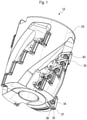
Fig. 1 is a perspective view showing an indexable rotary cutting tool according to an embodiment of the present invention. -
Fig. 2 is a side view showing the indexable rotary cutting tool ofFig. 1 . -
Fig. 3 is a side view showing a tool body used in an embodiment of an indexable rotary cutting tool according to the present invention. - Fig. 4 is a top view showing the tool body of
Fig. 3 from its proximal end side. -
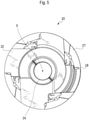
Fig. 5 is a bottom view showing the tool body ofFig. 3 from its distal end side. -
Fig. 6 is a perspective view showing a cutting insert used in an embodiment of an indexable rotary cutting tool according to the present invention. -
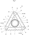
Fig. 7 is a top view showing the cutting insert ofFig. 6 . -
Fig. 8 is a diagram showing, by projection, the rotational trajectories of five cutting inserts, from the cutting insert located closest to a distal end to the cutting insert located closest to a proximal end, at a certain angular position in a tool rotating direction, in order to explain the rotational trajectories of wave shape major cutting edges of all the cutting inserts arranged in one groove of the tool body ofFig. 3 . -
Fig. 9 is a diagram showing portion IX inFig. 8 in an enlarged manner, in order to explain overlapping between rotational trajectories of adjacent cutting inserts in one groove. -
Fig. 10 is a diagram showing portion X inFig. 8 in an enlarged manner, in order to explain overlapping between rotational trajectories of circumferentially adjacent cutting inserts. - Embodiments of the present invention will now be described in detail with reference to the attached drawings. Although the expressions such as "upper," "lower," "front" and "back" may be used in the following description, such expressions are used to aid in easier understanding of the description and are intended to limit neither the absolute positional relationships in a space nor the scope of the present invention.
- An indexable
rotary cutting tool 10 according to the present embodiment is basically constituted by: a substantiallycylindrical tool body 20 having a plurality ofinsert seats 28; and a plurality ofcutting inserts 30 mounted on theinsert seats 28, as shown inFigs. 1 and2 . The indexablerotary cutting tool 10 of the present embodiment is sometimes referred to as a roughing cutter. - As shown in
Figs. 3-5 , thetool body 20 has a cylindrical shape including a substantially circularfirst end surface 21, asecond end surface 22 arranged so as to oppose thefirst end surface 21 and having a substantially circular shape similarly to thefirst end surface 21, and aperipheral surface 23 connecting theseend surfaces tool body 20 has a rotational axis O passing through a center point of thefirst end surface 21 and a center point of thesecond end surface 22. The indexablerotary cutting tool 10 rotates with respect to the rotational axis O. Thefirst end surface 21 is an end surface arranged at a proximal end of thetool body 20 and is also referred to as a proximal end surface. Herein, the proximal end of thetool body 20 refers to an end to be mounted on a machine tool. Thesecond end surface 22 is an end surface arranged at a distal end of thetool body 20 and is also referred to as a distal end surface. Herein, the distal end of thetool body 20 refers to an end which is to be brought closer to a work piece. - The
tool body 20 is provided with athrough hole 24 formed so as to extend from thefirst end surface 21 to thesecond end surface 22 along the rotational axis O and a plurality ofcoolant supply holes 25 through which coolant flows. An attachment bolt to be used for fixing thetool body 20 to an arbor in the machine tool is inserted into the throughhole 24. Thefirst end surface 21 is provided with an opening of the throughhole 24, openings of thecoolant supply holes 25, and akey groove 26 for transferring a motive force from the main shaft of the machine tool. Thesecond end surface 22 is provided with an opening of the throughhole 24 and notches resulting from the provision of theinsert seats 28. - A plurality of
grooves 27 is formed in a spiral manner in theperipheral surface 23 between thefirst end surface 21 and thesecond end surface 22 of thetool body 20. Thegrooves 27 are formed so as to be twisted counterclockwise from the proximal end toward the distal end, as viewed from the distal end surface of thetool body 20. Thegrooves 27 start in the vicinity of thefirst end surface 21 of thetool body 20 and reach thesecond end surface 22. Although fourgrooves 27 are provided in the present embodiment, the number ofgrooves 27 is not limited thereto and any number of grooves may be provided, as long as there are one or more grooves. The plurality ofinsert seats 28 is formed in areas of thegrooves 27 facing forward in the tool rotating direction. In the present embodiment, although fiveinsert seats 28 are provided in onegroove 27, the number ofinsert seats 28 is not limited thereto and two or moreinsert seats 28 may be provided in onegroove 27. On the other hand, a plurality ofcoolant ejection ports 29 for ejecting the coolant are provided in areas of thegrooves 27 facing opposite to the tool rotating direction. Thecoolant ejection ports 29 communicate with the coolant supply holes 25. The number, arrangement, etc. of thecoolant ejection ports 29 and the coolant supply holes 25 may be changed as appropriate, in accordance with a desired cooling performance, etc. - In a
common groove 27, in a side view of thetool body 20, theinsert seat 28 located closest to the distal end of the tool is defined as a first segment, theinsert seat 28 next to the first segment is defined as a second segment, theinsert seat 28 next to the second segment is defined as a third segment, theinsert seat 28 next to the third segment is defined as a fourth segment, and theinsert seat 28 closest to the proximal end is defined as a fifth segment (the uppermost segment). - As shown in
Fig. 3 , theinsert seat 28 is basically constituted by abottom surface 281 that is brought into contact with a lower surface (seating surface) 32 of the cuttinginsert 30 and twoside surfaces 282 that are brought into contact with a peripheral surface (restraining surface) 33 of the cuttinginsert 30. Thebottom surface 281 of the insert seat has a generally similar shape to the shape of the seating surface 32 of the cuttinginsert 30 to be attached thereto. Although the shape is substantially triangular in the present embodiment, the shape is not limited thereto. Thebottom surface 281 is provided with afixture hole 283 at substantially the center thereof for fixing the cuttinginsert 30 onto theinsert seat 28 by, for example, screwing. Specifically, although thefixture hole 283 inFig. 3 is shown in a simplified manner, an inner surface of theactual fixture hole 283 is provided with a female thread. The shapes of thebottom surface 281 and the side surfaces 282 of theinsert seat 28, as well as the positional relationship therebetween, may be changed as appropriate in accordance with the shape, etc. of the cutting insert to be mounted thereon. - As shown in
Figs. 6 and7 , the cuttinginsert 30 used in the present embodiment is basically constituted by: anupper surface 31 whose basic contour is a substantially regular triangle; a lower surface 32 arranged so as to oppose theupper surface 31 and having a substantially triangular shape; and aperipheral surface 33 connecting theupper surface 31 and the lower surface 32. More specifically, the cuttinginsert 30 has a shape in which a part near each vertex of the triangle is cut off by a line substantially orthogonal to one side of the triangle. Thus, it can also be said that theupper surface 31 has a hexagonal shape of 120 degrees rotational symmetry formed by alternately-intersecting long sides and short sides. An angle formed by theupper surface 31 and theperipheral surface 33 is an acute angle, while an angle formed by the lower surface 32 and theperipheral surface 33 is a blunt angle. Accordingly, this cuttinginsert 30 is a so-called positive type. Theupper surface 31 functions as a rake surface, theperipheral surface 33 functions as a flank or restraining surface, and the lower surface 32 functions as a seating surface. Anattachment hole 36 is formed so as to penetrate substantially the center of theupper surface 31 and the lower surface 32. - Part of intersecting edges between the
upper surface 31 and theperipheral surface 33 is provided with cutting edges. Specifically,major cutting edges 34 are formed on long side portions andminor cutting edges 35 are formed on short side portions. Further, acorner cutting edge 37 is formed on each corner at which the long side portion and the short side portion intersect with each other substantially at a right angle. Accordingly, since the cuttinginsert 30 of the present embodiment has three sets of amajor cutting edge 34, aminor cutting edge 35 and acorner cutting edge 37, by rotating the cutting insert by 120 degrees and attaching it onto theinsert seat 28 to use every set of cutting edges, asingle cutting insert 30 can perform cutting three times. - However, the shape and configuration of the cutting
insert 30 used for the indexablerotary cutting tool 10 according to the present invention are not limited thereto and may be changed as appropriate. For example, the cuttinginsert 30 may be of a negative-type in which theperipheral surface 33 intersects with theupper surface 31 and the lower surface 32 at 90 degrees. In such case, both the upper surface and the lower surface are formed in a congruent shape and, if the lower surface 32 is also provided with cutting edges, then the cutting insert is able to perform cutting six times in total by inverting the upper surface and the lower surface. The basic contour of the cutting insert may be other polygonal shapes, such as quadrangles and pentagons. - In the top view of the cutting insert 30 (
Fig. 7 ), themajor cutting edges 34 are formed in a wave shape. The "wave shape" as used herein refers to a shape formed by alternately connecting outwardly-curvedcutting edge portions 341 that are curved like arcs toward the outside of the cuttinginsert 30 and inwardly-curvedcutting edge portions 342 that are curved like arcs toward the inside of the cuttinginsert 30, in the top view of the cuttinginsert 30. However, all portions of the wave shape do not necessarily have to be arc-like curved portions and a part thereof may be formed linearly. In the present embodiment, themajor cutting edge 34 is formed in a wave shape throughout its length and formed in a sine wave. A portion of theperipheral surface 33 that is adjacent to the wave-shapemajor cutting edge 34 is also formed in a wave shape corresponding to the wave shape of themajor cutting edge 34. In such wave-shape cutting edge, since only peak portions (the outwardly-curved cutting edge portions 341) are basically involved in cutting, chips are separated into small pieces. In addition, since only part of the cutting edge is involved in cutting, cutting resistance can be reduced. Thus, such cutting insert is suitable for a tool that forms large depth of cut and thereby discharges a large amount of chips and has a high cutting resistance, such as a roughing cutter. - In the cutting
insert 30 according to the present embodiment, themajor cutting edge 34, thecorner cutting edge 37 and theminor cutting edge 35 along the respective sides of the triangle are connected in the order mentioned so as to form a set of cutting edges, as described above. Accordingly, aminor cutting edge 35 in a certain set is connected to anothermajor cutting edge 34 in an adjacent set. A connecting part A1 between theminor cutting edge 35 in the certain set and themajor cutting edge 34 in the adjacent set and a peripheral part of the connecting part A1 also function as aninner cutting edge 38. The "inner cutting edge" refers to a cutting edge that does not function in a normal lateral feeding (a feeding in a plane orthogonal to the axis of the tool) but is used when the tool is fed also in the axial direction of the tool, as in ramp cutting. In general, in a state in which the cuttinginsert 30 is mounted on the tool body as shown inFig. 1 , in theminor cutting edge 35 provided in the cutting insert located closest to the distal end and involved in cutting, a portion that is provided on a side opposite to the side to which thecorner cutting edge 37 is connected serves as theinner cutting edge 38. - In the present embodiment, a cutting edge portion that may serve as the
inner cutting edge 38 is a cutting edge portion that extends from the connecting part A1 between theminor cutting edge 35 in a certain set and themajor cutting edge 34 in the adjacent set by a certain length toward themajor cutting edge 34, as shown inFig. 7 . In other words, in the outwardly-curvedcutting edge portions 341 of themajor cutting edge 34, a part in the vicinity of an outwardly-curvedcutting edge portion 351 located closest to an end (connecting part A1) also serves as the inner cutting edge. In addition, the outwardly-curvedcutting edge portion 351 located closest to the end has a shape in which the position that is projected outermost in the top view is the connecting point A1 between themajor cutting edge 34 and theminor cutting edge 35, i.e., a shape that ends at the highest point (the middle point of the peak). - In the cutting
insert 30 according to the present embodiment, lands 39 are formed on all the cutting edges 34, 35 and 37, and the width and angle of these lands are not constant. The land width and the land angle are constant in areas extending from the center point C of themajor cutting edge 34 and before reaching the ends (i.e., the connecting point A1 between themajor cutting edge 34 and theminor cutting edge 35 of the adjacent set and a connecting point A2 between themajor cutting edge 34 and thecorner cutting edge 37 of the same set) of themajor cutting edge 34. Specifically, the land width is 0.15 mm and the land angle is 5°. On the other hand, the land width and the land angle vary in areas extending from points that are located slightly on the center point C side with respect to the respective connecting points A1, A2 to the connecting points A1, A2, in themajor cutting edge 34. In such areas, the land width varies so as to become larger and the land angle varies so as to become smaller, from the center point C side toward the connecting points A1, A2. At the connecting points A1, A2, the land width becomes the largest and the land angle becomes the smallest. Specifically, at the connecting points A1, A2, the land width is 0.2 mm and the land angle is 0°. The land width and the land angle of the lands 39 in thecorner cutting edge 37 and theminor cutting edge 35 are the same, throughout their lengths, as the land width and the land angle at the connecting points A1, A2 between suchcorner cutting edge 37 andminor cutting edge 35 and themajor cutting edge 34. Accordingly, the land width is 0.2 mm and the land angle is 0° in theminor cutting edge 35 and themajor cutting edge 34. - Such cutting insert 30 is mounted on the
insert seat 28 of thetool body 20 by afastening screw 40. At this time, the lower surface 32 of the cuttinginsert 30 is brought into contact with thebottom surface 281 of theinsert seat 28. In addition, theperipheral surfaces 33 of the cuttinginsert 30 are brought into contact with the side surfaces 282 of theinsert seat 28. At this time, the cuttinginsert 30 is mounted so as to be arranged in positional relationships in which themajor cutting edge 34 is parallel to theperipheral surface 23 of thetool body 20 on theperipheral surface 23 side and theminor cutting edge 35 is parallel to a distal end surface of thetool body 20 on the distal end surface side, as shown inFig. 2 . A wedge, a presser piece, etc. can be used, other than thefastening screw 40, to fix the cuttinginsert 30. However, by forming theattachment hole 36 so that the diameter of its end parts is larger than that of its central part and bringing a head part of thefastening screw 40 into contact with stepped portions formed by such larger diameter parts of the attachment hole to thereby fix the cuttinginsert 30 to thetool body 20, it is possible to eliminate projections projected in thegroove 27. Thus, the discharging efficiency of chips can be enhanced. - The cutting edges 34, 35, 37 of the cutting
insert 30 can be made of hard materials, such as a cemented carbide, cermet, ceramic, a material obtained by applying some coating to these materials, an ultrahigh-pressure sintered body containing diamond or cubic boron nitride, and a material obtained by applying some coating to the ultrahigh-pressure sintered body containing cubic boron nitride. The remaining parts other than the cutting edges 34, 35, 37 of the cuttinginsert 30 are preferably made of similarly hard materials. - In the present embodiment, five cutting inserts 30 are mounted per one
groove 27. In the firstsegment cutting insert 30 arranged closest to the distal end of the tool, themajor cutting edge 34 thereof is involved in cutting of a side surface of a work piece, theminor cutting edge 35 thereof is involved in cutting of a bottom surface of the work piece and thecorner cutting edge 37 thereof is involved in cutting of a corner of the work piece. On the other hand, in the second to fifth segment cutting inserts 30, theminor cutting edges 35 and thecorner cutting edges 37 are not involved in cutting of the work piece, although themajor cutting edges 34 thereof are involved in cutting of the side surface of the work piece. In other words, theminor cutting edges 35 and thecorner cutting edges 37 of the second to fifth segment cutting inserts 30 are arranged so as not to be projected with respect to the rotational trajectories of themajor cutting edges 34 of the corresponding cutting inserts 30 in the other grooves. - The cutting inserts 30 are arranged in an overlapped manner in one
groove 27 in the direction of the rotational axis O in the side view of thetool body 20. More specifically, themajor cutting edges 34 of adjacent cutting inserts 30 in one groove are arranged such that their cutting portions are overlapped in the direction of the rotational axis O. Since the insert seats 28 are formed in a stair-like shape in thespiral groove 27 as shown inFig. 2 , such overlapped arrangement of the cutting inserts 30 can be achieved. - The cutting inserts 30 are arranged so as to be partially overlapped in the direction of the rotational axis O in one
groove 27, as described above. More specifically, the cutting inserts 30 have the following characteristic configurations. -
Fig. 8 shows a state in which rotational trajectories 301-305 of five cutting inserts, i.e., from the cutting insert located closest to the distal end to the cutting insert located closest to the proximal end, are projected at a certain angular position in the tool rotating direction. As shown inFig. 8 , as viewed from the front side of the rotational trajectories formed by themajor cutting edges 34 of the respective cutting inserts 30 when the indexablerotary cutting tool 10 according to the present embodiment is rotated around the rotational axis O, the cutting inserts 30 are arranged so as to be overlapped in the direction of the rotational axis O such that the phases of the waves of the rotational trajectories 301-305 formed by the adjacent cutting inserts 30 coincide with each other. In other words, the cutting inserts 30 are arranged such that the waves of the rotational trajectories formed by themajor cutting edges 34 of the cutting inserts 30 are formed continuously between the adjacent cutting inserts 30. - In the present embodiment, as shown in
Fig. 9 , which shows portion IX inFig. 8 in an enlarged manner, the cutting inserts 30 are arranged such that, in the rotational trajectories formed by the major cutting edges 34 (therotational trajectories Fig. 9 ) only the rotational trajectories formed by the respective outwardly-curvedcutting edge portions 341 located closest to the ends of themajor cutting edge 34 are overlapped in the direction of the rotational axis O, in eachgroove 27. This relates to, more precisely, the relationship between the rotational trajectory of the outwardly-curvedcutting edge portion 351 of a cutting insert located relatively closer to the distal end and the rotational trajectory of the outwardly-curvedcutting edge portion 341 connected to the corner cutting edge of a cutting insert located relatively closer to the proximal end. In the present embodiment, the same relationship is applied to all the adjacent cutting inserts 30 in all thegrooves 27. - In addition, in the relationship between the
adjacent grooves 27 in the circumferential direction of the tool, the cutting inserts 30 are arranged in such a way that the phases of the waves of the rotational trajectories of thecutting tool 10 are shifted in the direction of the rotational axis O of the tool, so that the phases of the waves of the rotational trajectories of thegrooves 27 do not coincide with each other when the rotational trajectories of all thegrooves 27 are superimposed. Specifically, as shown inFig. 10 , which shows portion X inFig. 8 in an enlarged manner, in the relationship between the first segment cutting inserts located closest to the distal end in thegrooves 27 that are adjacent to each other in the circumferential direction, the phase of the wave of the rotational trajectory shown by the broken line is shifted with respect to therotational trajectory 301 shown in the solid line of the circumferentially adjacent cutting insert. - Next, the effects and advantages of the indexable
rotary cutting tool 10 according to the present embodiment will now be described. - The following advantages can be obtained by configurations in which:
- the cutting inserts 30 each have the
major cutting edge 34 formed in a wave shape in plan view; the cutting inserts 30 are arranged such that, in the rotational trajectories formed by themajor cutting edges 34 of the respective cutting inserts 30 when the indexablerotary cutting tool 10 is rotated around the rotational axis O, the phases of the waves of the rotary trajectories formed by the cutting inserts 30 that are adjacent to each other along the direction of the rotational axis O coincide with each other in onegroove 27; - and at least some of the cutting inserts 30 are arranged such that the rotational trajectories formed by part of cutting edge portions from among the rotational trajectories formed by the
major cutting edges 34 are overlapped with each other in the direction of the rotational axis O, as in the indexablerotary cutting tool 10 according to the present embodiment. - The configurations in which the phases of the wave-like rotational trajectories of the adjacent cutting inserts 30 coincide with each other and the rotational trajectories formed by part of the cutting edge portions are overlapped indicate that at least the outwardly-curved
cutting edge portions 341 located closest to an end (the connecting point A1) of themajor cutting edges 34 are overlapped in the circumferential direction in the present embodiment. In the cuttinginsert 30 of the present embodiment, the outwardly-curvedcutting edge portion 351 of themajor cutting edge 34 can also serve as theinner cutting edge 38. Thus, in the cuttinginsert 30 arranged closest to the distal end of the tool, only such outwardly-curvedcutting edge portion 351 is used for cutting twice, i.e., the cutting of the side surface and the cutting of the bottom surface of a work piece. In other words, the outwardly-curvedcutting edge portion 351 is used as themajor cutting edge 34 and is also used as theinner cutting edge 38. - Accordingly, the outwardly-curved
cutting edge portion 351 is subjected to quite a large load and is prone to breakage. However, by employing the configurations in the present embodiment, such problems can be suppressed. This is because, in an area corresponding to the outwardly-curvedcutting edge portion 351 in the rotating direction, there are twice as many cutting edges as in the other cutting edge portions. In other words, an area in the vicinity of the outwardly-cutting edge portion 351 is overlapped with an area in the vicinity of the outwardly-curvedcutting edge portion 341 at an end of the adjacent cutting insert and, further, since thetool body 20 is provided with four grooves, from among themajor cutting edges 34, four cutting edges are used for cutting in areas corresponding to the other cutting edge portions in the rotating direction whereas eight cutting edges are used for cutting in the area corresponding to the overlapped outwardly-curvedcutting edge portions 351 in the rotating direction. Accordingly, since the thickness of cut per cutting edge is small in such area, the cutting load can be greatly reduced. As described above, by greatly reducing the load applied to the outwardly-curvedcutting edge portions 341 that are used for cutting twice, it is possible to significantly suppress fracture in such portion that is used also as theinner edge 38. - In the present embodiment, the cutting inserts 30 are arranged so as to be overlapped in the direction of the rotational axis O such that only the rotational trajectories formed by the outwardly-curved
cutting edge portions 341 located closest to the end of the major cutting edges 34 (i.e., the outwardly-curvedcutting edge portion 351 corresponding to theinner cutting edge 38 of a cutting insert located relatively closer to the distal end and the outwardly-curvedcutting edge portion 341 connected to the corner cutting edge of a cutting insert located relatively closer to the proximal end) coincide with each other, from among the rotational trajectories formed by the major cutting edges 34. However, the arrangement is not limited thereto. Specifically, the cutting inserts 30 may be arranged such that the rotational trajectories formed by more than one outwardly-curved cutting edge 341 from the end are overlapped with each other. However, in order to maximize the depth of cut provided by the entire tool, the arrangement in which only the portions located closest to the end are overlapped is preferable. - Although all the adjacent cutting inserts 30 are overlapped with each other in all the
grooves 27 in the present embodiment, the arrangement is not limited thereto. Specifically, the effect of suppressing fracture in the outwardly-curvedcutting edge portions 351 can be achieved to some extent even by a configuration in which only some of theadjacent inserts 30 in some of thegrooves 27 are overlapped with each other. However, in order to maximize the fracture suppressing effect, the arrangement in which all the adjacent cutting inserts 30 are overlapped with each other in all thegrooves 27 is preferable. The cuttinginsert 30 whose outwardly-curvedcutting edge portion 351 serves as theinner cutting edge 38 is only the cutting insert located closest to the distal end. This is because, when all the cutting inserts in the tool are replaced at the same time, the cutting insert that has been located closest to the distal end is replaced with the cutting insert that has been located closest to the proximal end for use. - In the
grooves 27 that are adjacent to each other in the circumferential direction of the tool, the cutting inserts 30 are arranged such that the phases of the waves of the rotational trajectories are shifted in the direction of the tool rotational axis O and such that, when the rotational trajectories of all thegrooves 27 are superimposed, the phases of the waves of the rotational trajectories ofsuch grooves 27 do not coincide with each other. With such arrangement, the height difference between the peak portions and valley portions of the wave-like rotational trajectories of themajor cutting edges 34 is reduced when all thegrooves 27 are superimposed, the amount of portions that remain uncut due to the valley portions can be reduced and the surface roughness of a worked surface of a work piece can be enhanced. - The lands 39 are formed in all of the
major cutting edges 34, theminor cutting edges 35 and thecorner cutting edge 37 in the cutting inserts 30 and the land width at the connecting point A1 between themajor cutting edge 34 and theminor cutting edge 35 is larger than the land width at the center point C of themajor cutting edge 34 while the land angle at the connecting point A1 is smaller than the land angle at the center point C. With such configuration, the strength of the portion (the outwardly-curved cutting edge portion 351) of themajor cutting edge 34 that corresponds to theinner cutting edge 38 can be enhanced and fracture can be further suppressed. - In addition, in the abovementioned configuration in which the phases of the waves of the rotational trajectories of the
grooves 27 are shifted from each other in the direction of the tool rotational axis O, since only theinner cutting edge 38 of the cuttinginsert 30 located closest to the distal end of the tool in eachgroove 27 is first brought into contact with the bottom surface of a work piece, the number of cutting edges involved in cutting is small in this state. For example, in all thegrooves 27, an area corresponding to theinner cutting edge 38 of the cuttinginsert 30 located closest to the distal end of the tool contains one cutting edge, an area corresponding to theinner cutting edge 38 of the cuttinginsert 30 located second closest to the distal end contains two cutting edges, and an area corresponding to theinner cutting edge 38 of the cuttinginsert 30 located third closest to the distal end contains three cutting edges. Accordingly, cutting resistances applied to theseinner cutting edges 38 are larger than the cutting resistance applied to the normal inner cutting edge, i.e., an area corresponding to theinner cutting edge 38 of the cuttinginsert 30 located fourth closest to the distal end of the tool and containing four cutting edges, and thus, the configuration of strengthening the lands as described above is effective. At the same time, in the other portions of the major cutting edge 34 (the portions that are not used for cutting twice), the lands 39 are kept sharp, so that the cutting performance can be maintained. - In addition, the land width and land angle of the
minor cutting edge 35 are preferably equal to the land width and land angle at the connecting point A1. Such configuration can enhance the strength of theminor cutting edge 35 to which a large load is applied in the configuration in which thegrooves 27 are arranged such that the phases of the waves of their rotational trajectories are shifted from each other in the direction of axis O of the tool, as described above. - The shape of the cutting inserts 30 used in the present invention does not have to be limited to the triangular shape in plan view. In other words, other shapes may be employed, as long as the cutting
insert 30 has the configuration in which part of themajor cutting edge 34 is also used as theinner cutting edge 38. - Although representative embodiments of the present invention have been described above, various modifications may be made to the present invention and any replacement and modification may be made without departing from the scope of the invention defined in the claims of the present application.
Claims (6)
- An indexable rotary cutting tool (10) comprising: a substantially cylindrical tool body (20) having a rotational axis (O); and cutting inserts (30) mounted on the tool body (20), in which a plurality of grooves (27) is formed in a peripheral surface (23) of the tool body (20), a plurality of insert seats (28) is formed in the grooves (27), and the cutting inserts (30) are removably arranged onto the insert seats (27), wherein:the cutting inserts (30) each have a rake surface (31) and a flank (33) intersecting with the rake surface (31), and a major cutting edge (34), a corner cutting edge (37) connected to the major cutting edge (34), and a minor cutting edge (35) connected to the corner cutting edge (37), are formed in an intersecting edge between the rake surface (31) and the flank (33);the major cutting edge (34) is formed along each side of the rake surface (31) of the cutting insert (30) and is in a wave shape as viewed from a direction facing the rake surface (31) andthe cutting inserts (30) are arranged such that, in rotational trajectories formed by the major cutting edges (34) of the respective cutting inserts (30) when the indexable rotary cutting tool (10) is rotated around the rotational axis (O), phases of waves of rotational trajectories formed by cutting inserts (30) that are adjacent to each other in a direction along the rotational axis (O) in one groove (27) coincide with each other, and such that at least some of the cutting inserts (30) are arranged such that, from among the rotational trajectories formed by the major cutting edges (34), rotational trajectories formed by part of cutting edge portions are overlapped with each other in a direction of the rotational axis (O), whereinthe major cutting edge (34) is formed in a wave shape having a plurality of outwardly-curved cutting edge portions (341) that are curved outwardly as viewed from
the direction facing the rake surface (31); and characterised in thatin each of the grooves (27), the at least some cutting inserts (30) are arranged such that, from among the rotational trajectories formed by the major cutting edges (34), only rotational trajectories formed by outwardly-curved cutting edge portions (341) located closest to ends of the major cutting edges (34) are overlapped with each other in the direction of the rotational axis (O) and, wherein:in the plurality of outwardly-curved cutting edge portions (341), an outwardly-curved cutting edge portion (351) located at an end of the major cutting edge (34) and connected to the minor cutting edge (35) is configured to also serve as an inner cutting edge (38). - The indexable rotary cutting tool (10) according to claim 1, wherein, in all the grooves (27), all adjacent cutting inserts (30) are arranged such that the rotational trajectories of the ends are overlapped with each other in the direction of the rotational axis (O).
- The indexable rotary cutting tool (10) according to any one of claims 1 or 2, wherein, in a relationship between the rotational trajectories of the cutting inserts arranged in grooves (27) that are adjacent to each other in a circumferential direction of the tool body (20), the cutting inserts (30) are arranged such that the phases of the waves of the rotational trajectories are shifted from each other in the direction of the rotational axis (O), and when the rotational trajectories of all the grooves (27) are superimposed, the phases of the waves of the rotational trajectories of the grooves (27) do not coincide with each other.
- The indexable rotary cutting tool (10) according to any one of claims 1 to 3, wherein:the minor cutting edge (35) of the cutting insert (30) is connected to a different major cutting edge (34) from said major cutting edge (34);lands (39) are formed in all of the major cutting edge (34), the minor cutting edge (35), and the corner cutting edge (37);a land width at a connecting point (A1) between said different major cutting edge (34) and the minor cutting edge (35) is larger than a land width at a center point (C) in the different major cutting edge (34); anda land angle at the connecting point (A1) between the different major cutting edge (34) and the minor cutting edge (35) is smaller than a land angle at the center point (C) in the different major cutting edge (34).
- The indexable rotary cutting tool (10) according to claim 4, wherein a land width and a land angle of the minor cutting edge (35) are equal to the land width and the land angle at the connecting point (A1).
- The indexable rotary cutting tool (10) according to any one of claims 1 to 5, wherein the cutting inserts (30) have a substantially triangular shape as viewed from a direction facing the rake surface (31).
Applications Claiming Priority (2)
| Application Number | Priority Date | Filing Date | Title |
|---|---|---|---|
| JP2014143780 | 2014-07-14 | ||
| PCT/JP2015/070057 WO2016009995A1 (en) | 2014-07-14 | 2015-07-13 | Replaceable edge-type rotating cutting tool |
Publications (3)
| Publication Number | Publication Date |
|---|---|
| EP3147057A1 EP3147057A1 (en) | 2017-03-29 |
| EP3147057A4 EP3147057A4 (en) | 2017-09-13 |
| EP3147057B1 true EP3147057B1 (en) | 2022-03-02 |
Family
ID=55078487
Family Applications (1)
| Application Number | Title | Priority Date | Filing Date |
|---|---|---|---|
| EP15821813.1A Active EP3147057B1 (en) | 2014-07-14 | 2015-07-13 | Indexable rotary cutting tool |
Country Status (5)
| Country | Link |
|---|---|
| US (1) | US10124423B2 (en) |
| EP (1) | EP3147057B1 (en) |
| JP (1) | JP6011831B2 (en) |
| CN (1) | CN105813785B (en) |
| WO (1) | WO2016009995A1 (en) |
Families Citing this family (6)
| Publication number | Priority date | Publication date | Assignee | Title |
|---|---|---|---|---|
| US10556278B2 (en) * | 2016-08-16 | 2020-02-11 | Kennametal Inc. | Tool body for a shell end mill and cutting tool |
| CN106825719B (en) * | 2016-12-30 | 2019-12-06 | 株洲钻石切削刀具股份有限公司 | Cutting insert |
| CN106862618B (en) * | 2016-12-30 | 2019-12-13 | 株洲钻石切削刀具股份有限公司 | Drilling machining tool |
| CN107234285B (en) * | 2017-05-17 | 2020-07-17 | 贺州学院 | Formed milling cutter and manufacturing method thereof |
| CN112108697A (en) | 2019-06-20 | 2020-12-22 | 肯纳金属印度有限公司 | Tool holder with pockets for receiving cutting inserts having different clearance angles |
| US11806796B2 (en) * | 2021-03-15 | 2023-11-07 | Kennametal Inc. | Cutting insert and cutting tool comprising cutting insert |
Family Cites Families (19)
| Publication number | Priority date | Publication date | Assignee | Title |
|---|---|---|---|---|
| US4936719A (en) | 1976-08-24 | 1990-06-26 | Greenleaf Corporation | Cutter and indexable on edge inserts with aligned corners and staggered serrated edges |
| JPH0135777Y2 (en) * | 1985-05-25 | 1989-11-01 | ||
| US4844666A (en) * | 1986-08-22 | 1989-07-04 | Izumo Industrial Co., Ltd. | Insert rotary cutting tool |
| CA1270631A (en) * | 1987-02-06 | 1990-06-26 | Robert Theodore Koblesky | Interfitting on-edge inserts for milling cutters |
| CA2062213C (en) * | 1992-03-03 | 1996-07-16 | Alfonso Minicozzi | Indexable cutting insert for rotary cutting tools |
| US5542792A (en) * | 1993-12-21 | 1996-08-06 | Waukesha Cutting Tools, Inc. | Cutting device with removable nosepiece |
| JPH0839308A (en) | 1994-07-26 | 1996-02-13 | Mitsubishi Materials Corp | Throwaway tip |
| IL119114A0 (en) * | 1996-08-22 | 1996-11-14 | Iscar Ltd | Cutting insert |
| US5913644A (en) * | 1998-04-20 | 1999-06-22 | Kennametal Inc. | Helical mill having multiple flutes with differing rake angles |
| DE10043015C2 (en) * | 2000-09-01 | 2002-09-19 | Walter Ag | Cutting tool with direct insert system |
| US6811359B2 (en) * | 2002-05-31 | 2004-11-02 | Kennametal Inc. | True helical cutter system |
| US7563059B2 (en) * | 2006-04-21 | 2009-07-21 | Yg-1 Co., Ltd. | Sinusoidal angled rotary cutting tool |
| JP5023628B2 (en) | 2006-09-13 | 2012-09-12 | 三菱マテリアル株式会社 | Roughing end mill |
| EP2060353B1 (en) * | 2006-09-13 | 2012-12-19 | Mitsubishi Materials Corporation | Roughing insert, and roughing end mill |
| US8613574B2 (en) * | 2008-02-22 | 2013-12-24 | Kennametal Inc. | Helical milling cutter |
| US8696257B2 (en) * | 2009-03-06 | 2014-04-15 | Mitsubishi Materials Corporation | Cutting insert and removable insert-type cutting tool |
| KR101097658B1 (en) * | 2009-05-29 | 2011-12-22 | 대구텍 유한회사 | Cutting insert |
| JP2013202770A (en) | 2012-03-29 | 2013-10-07 | Mitsubishi Materials Corp | Blade edge replaceable end mill and end mill main body used for the same |
| US9505066B2 (en) * | 2014-08-01 | 2016-11-29 | Kennametal Inc. | Rotary cutting tool with regrindable cutting inserts |
-
2015
- 2015-07-13 US US15/312,755 patent/US10124423B2/en active Active
- 2015-07-13 EP EP15821813.1A patent/EP3147057B1/en active Active
- 2015-07-13 WO PCT/JP2015/070057 patent/WO2016009995A1/en active Application Filing
- 2015-07-13 CN CN201580003184.XA patent/CN105813785B/en active Active
- 2015-07-13 JP JP2015543211A patent/JP6011831B2/en active Active
Also Published As
| Publication number | Publication date |
|---|---|
| JP6011831B2 (en) | 2016-10-19 |
| EP3147057A4 (en) | 2017-09-13 |
| US10124423B2 (en) | 2018-11-13 |
| WO2016009995A1 (en) | 2016-01-21 |
| EP3147057A1 (en) | 2017-03-29 |
| CN105813785A (en) | 2016-07-27 |
| US20170189974A1 (en) | 2017-07-06 |
| JPWO2016009995A1 (en) | 2017-04-27 |
| CN105813785B (en) | 2017-08-18 |
Similar Documents
| Publication | Publication Date | Title |
|---|---|---|
| EP3147057B1 (en) | Indexable rotary cutting tool | |
| JP6532940B2 (en) | Double-sided cutting inserts and milling tools | |
| JP5023628B2 (en) | Roughing end mill | |
| US5145294A (en) | Milling cutter capable of using indexable inserts of various shapes | |
| EP3266547B1 (en) | Cutting insert and cutting edge-replaceable rotary cutting tool | |
| US20200368830A1 (en) | Indexable rotary cutting tool and tool body | |
| EP3175945B1 (en) | Cutting insert and replaceable cutting edge cutting tool | |
| EP2489454A1 (en) | Cutting insert and rotary tool with a replaceable blade edge | |
| WO2017122715A1 (en) | Cutting insert and blade-tip-replaceable cutting tool | |
| KR20140106538A (en) | Cutting insert and interchangeable cutting edge-type cutting tool | |
| JP7098538B2 (en) | Star-shaped cutting inserts for rotary milling cutters for front and back | |
| JP2008229744A (en) | Cutting insert and insert removable rotary cutting tool | |
| JP6361948B2 (en) | Cutting inserts and cutting tools | |
| JP2014136264A (en) | Cutting insert for face milling cutter and cutting edge replaceable face milling cutter | |
| EP3112067B1 (en) | Indexable rotary cutting tool | |
| JP7101679B2 (en) | Cutting inserts and shoulder milling tools | |
| WO2014021314A1 (en) | Cutting insert, and replaceable-blade-edge cutting tool | |
| EP3233340B1 (en) | Rotary cutting tool having a predetermined number of left and right handed helical flutes and end face cutting teeth | |
| JP5483872B2 (en) | Cutting insert, cutting tool and cutting method using them | |
| CN104439460A (en) | Indexable end mill for rough machining | |
| JP6004301B2 (en) | Cutting insert and cutting edge exchangeable rotary cutting tool | |
| JP6318558B2 (en) | Cutting insert and replaceable edge drilling tool | |
| CN117206606A (en) | Thread milling cutter | |
| JPH04130115U (en) | Throwaway end mill |
Legal Events
| Date | Code | Title | Description |
|---|---|---|---|
| PUAI | Public reference made under article 153(3) epc to a published international application that has entered the european phase |
Free format text: ORIGINAL CODE: 0009012 |
|
| STAA | Information on the status of an ep patent application or granted ep patent |
Free format text: STATUS: REQUEST FOR EXAMINATION WAS MADE |
|
| 17P | Request for examination filed |
Effective date: 20160701 |
|
| AK | Designated contracting states |
Kind code of ref document: A1 Designated state(s): AL AT BE BG CH CY CZ DE DK EE ES FI FR GB GR HR HU IE IS IT LI LT LU LV MC MK MT NL NO PL PT RO RS SE SI SK SM TR |
|
| AX | Request for extension of the european patent |
Extension state: BA ME |
|
| A4 | Supplementary search report drawn up and despatched |
Effective date: 20170810 |
|
| RIC1 | Information provided on ipc code assigned before grant |
Ipc: B23C 5/20 20060101ALI20170804BHEP Ipc: B23C 5/10 20060101AFI20170804BHEP |
|
| DAV | Request for validation of the european patent (deleted) | ||
| DAX | Request for extension of the european patent (deleted) | ||
| GRAP | Despatch of communication of intention to grant a patent |
Free format text: ORIGINAL CODE: EPIDOSNIGR1 |
|
| STAA | Information on the status of an ep patent application or granted ep patent |
Free format text: STATUS: GRANT OF PATENT IS INTENDED |
|
| INTG | Intention to grant announced |
Effective date: 20210922 |
|
| GRAS | Grant fee paid |
Free format text: ORIGINAL CODE: EPIDOSNIGR3 |
|
| GRAA | (expected) grant |
Free format text: ORIGINAL CODE: 0009210 |
|
| STAA | Information on the status of an ep patent application or granted ep patent |
Free format text: STATUS: THE PATENT HAS BEEN GRANTED |
|
| AK | Designated contracting states |
Kind code of ref document: B1 Designated state(s): AL AT BE BG CH CY CZ DE DK EE ES FI FR GB GR HR HU IE IS IT LI LT LU LV MC MK MT NL NO PL PT RO RS SE SI SK SM TR |
|
| REG | Reference to a national code |
Ref country code: GB Ref legal event code: FG4D |
|
| REG | Reference to a national code |
Ref country code: CH Ref legal event code: EP Ref country code: AT Ref legal event code: REF Ref document number: 1471852 Country of ref document: AT Kind code of ref document: T Effective date: 20220315 |
|
| REG | Reference to a national code |
Ref country code: DE Ref legal event code: R096 Ref document number: 602015077285 Country of ref document: DE |
|
| REG | Reference to a national code |
Ref country code: IE Ref legal event code: FG4D |
|
| REG | Reference to a national code |
Ref country code: LT Ref legal event code: MG9D |
|
| REG | Reference to a national code |
Ref country code: NL Ref legal event code: MP Effective date: 20220302 |
|
| PG25 | Lapsed in a contracting state [announced via postgrant information from national office to epo] |
Ref country code: SE Free format text: LAPSE BECAUSE OF FAILURE TO SUBMIT A TRANSLATION OF THE DESCRIPTION OR TO PAY THE FEE WITHIN THE PRESCRIBED TIME-LIMIT Effective date: 20220302 Ref country code: RS Free format text: LAPSE BECAUSE OF FAILURE TO SUBMIT A TRANSLATION OF THE DESCRIPTION OR TO PAY THE FEE WITHIN THE PRESCRIBED TIME-LIMIT Effective date: 20220302 Ref country code: NO Free format text: LAPSE BECAUSE OF FAILURE TO SUBMIT A TRANSLATION OF THE DESCRIPTION OR TO PAY THE FEE WITHIN THE PRESCRIBED TIME-LIMIT Effective date: 20220602 Ref country code: LT Free format text: LAPSE BECAUSE OF FAILURE TO SUBMIT A TRANSLATION OF THE DESCRIPTION OR TO PAY THE FEE WITHIN THE PRESCRIBED TIME-LIMIT Effective date: 20220302 Ref country code: HR Free format text: LAPSE BECAUSE OF FAILURE TO SUBMIT A TRANSLATION OF THE DESCRIPTION OR TO PAY THE FEE WITHIN THE PRESCRIBED TIME-LIMIT Effective date: 20220302 Ref country code: ES Free format text: LAPSE BECAUSE OF FAILURE TO SUBMIT A TRANSLATION OF THE DESCRIPTION OR TO PAY THE FEE WITHIN THE PRESCRIBED TIME-LIMIT Effective date: 20220302 Ref country code: BG Free format text: LAPSE BECAUSE OF FAILURE TO SUBMIT A TRANSLATION OF THE DESCRIPTION OR TO PAY THE FEE WITHIN THE PRESCRIBED TIME-LIMIT Effective date: 20220602 |
|
| REG | Reference to a national code |
Ref country code: AT Ref legal event code: MK05 Ref document number: 1471852 Country of ref document: AT Kind code of ref document: T Effective date: 20220302 |
|
| PG25 | Lapsed in a contracting state [announced via postgrant information from national office to epo] |
Ref country code: PL Free format text: LAPSE BECAUSE OF FAILURE TO SUBMIT A TRANSLATION OF THE DESCRIPTION OR TO PAY THE FEE WITHIN THE PRESCRIBED TIME-LIMIT Effective date: 20220302 Ref country code: LV Free format text: LAPSE BECAUSE OF FAILURE TO SUBMIT A TRANSLATION OF THE DESCRIPTION OR TO PAY THE FEE WITHIN THE PRESCRIBED TIME-LIMIT Effective date: 20220302 Ref country code: GR Free format text: LAPSE BECAUSE OF FAILURE TO SUBMIT A TRANSLATION OF THE DESCRIPTION OR TO PAY THE FEE WITHIN THE PRESCRIBED TIME-LIMIT Effective date: 20220603 Ref country code: FI Free format text: LAPSE BECAUSE OF FAILURE TO SUBMIT A TRANSLATION OF THE DESCRIPTION OR TO PAY THE FEE WITHIN THE PRESCRIBED TIME-LIMIT Effective date: 20220302 |
|
| PG25 | Lapsed in a contracting state [announced via postgrant information from national office to epo] |
Ref country code: NL Free format text: LAPSE BECAUSE OF FAILURE TO SUBMIT A TRANSLATION OF THE DESCRIPTION OR TO PAY THE FEE WITHIN THE PRESCRIBED TIME-LIMIT Effective date: 20220302 |
|
| PG25 | Lapsed in a contracting state [announced via postgrant information from national office to epo] |
Ref country code: SM Free format text: LAPSE BECAUSE OF FAILURE TO SUBMIT A TRANSLATION OF THE DESCRIPTION OR TO PAY THE FEE WITHIN THE PRESCRIBED TIME-LIMIT Effective date: 20220302 Ref country code: SK Free format text: LAPSE BECAUSE OF FAILURE TO SUBMIT A TRANSLATION OF THE DESCRIPTION OR TO PAY THE FEE WITHIN THE PRESCRIBED TIME-LIMIT Effective date: 20220302 Ref country code: RO Free format text: LAPSE BECAUSE OF FAILURE TO SUBMIT A TRANSLATION OF THE DESCRIPTION OR TO PAY THE FEE WITHIN THE PRESCRIBED TIME-LIMIT Effective date: 20220302 Ref country code: PT Free format text: LAPSE BECAUSE OF FAILURE TO SUBMIT A TRANSLATION OF THE DESCRIPTION OR TO PAY THE FEE WITHIN THE PRESCRIBED TIME-LIMIT Effective date: 20220704 Ref country code: EE Free format text: LAPSE BECAUSE OF FAILURE TO SUBMIT A TRANSLATION OF THE DESCRIPTION OR TO PAY THE FEE WITHIN THE PRESCRIBED TIME-LIMIT Effective date: 20220302 Ref country code: CZ Free format text: LAPSE BECAUSE OF FAILURE TO SUBMIT A TRANSLATION OF THE DESCRIPTION OR TO PAY THE FEE WITHIN THE PRESCRIBED TIME-LIMIT Effective date: 20220302 Ref country code: AT Free format text: LAPSE BECAUSE OF FAILURE TO SUBMIT A TRANSLATION OF THE DESCRIPTION OR TO PAY THE FEE WITHIN THE PRESCRIBED TIME-LIMIT Effective date: 20220302 |
|
| PG25 | Lapsed in a contracting state [announced via postgrant information from national office to epo] |
Ref country code: IS Free format text: LAPSE BECAUSE OF FAILURE TO SUBMIT A TRANSLATION OF THE DESCRIPTION OR TO PAY THE FEE WITHIN THE PRESCRIBED TIME-LIMIT Effective date: 20220702 Ref country code: AL Free format text: LAPSE BECAUSE OF FAILURE TO SUBMIT A TRANSLATION OF THE DESCRIPTION OR TO PAY THE FEE WITHIN THE PRESCRIBED TIME-LIMIT Effective date: 20220302 |
|
| REG | Reference to a national code |
Ref country code: DE Ref legal event code: R097 Ref document number: 602015077285 Country of ref document: DE |
|
| PLBE | No opposition filed within time limit |
Free format text: ORIGINAL CODE: 0009261 |
|
| STAA | Information on the status of an ep patent application or granted ep patent |
Free format text: STATUS: NO OPPOSITION FILED WITHIN TIME LIMIT |
|
| PG25 | Lapsed in a contracting state [announced via postgrant information from national office to epo] |
Ref country code: DK Free format text: LAPSE BECAUSE OF FAILURE TO SUBMIT A TRANSLATION OF THE DESCRIPTION OR TO PAY THE FEE WITHIN THE PRESCRIBED TIME-LIMIT Effective date: 20220302 |
|
| 26N | No opposition filed |
Effective date: 20221205 |
|
| PG25 | Lapsed in a contracting state [announced via postgrant information from national office to epo] |
Ref country code: SI Free format text: LAPSE BECAUSE OF FAILURE TO SUBMIT A TRANSLATION OF THE DESCRIPTION OR TO PAY THE FEE WITHIN THE PRESCRIBED TIME-LIMIT Effective date: 20220302 Ref country code: MC Free format text: LAPSE BECAUSE OF FAILURE TO SUBMIT A TRANSLATION OF THE DESCRIPTION OR TO PAY THE FEE WITHIN THE PRESCRIBED TIME-LIMIT Effective date: 20220302 |
|
| REG | Reference to a national code |
Ref country code: CH Ref legal event code: PL |
|
| GBPC | Gb: european patent ceased through non-payment of renewal fee |
Effective date: 20220713 |
|
| REG | Reference to a national code |
Ref country code: BE Ref legal event code: MM Effective date: 20220731 |
|
| PG25 | Lapsed in a contracting state [announced via postgrant information from national office to epo] |
Ref country code: LU Free format text: LAPSE BECAUSE OF NON-PAYMENT OF DUE FEES Effective date: 20220713 Ref country code: LI Free format text: LAPSE BECAUSE OF NON-PAYMENT OF DUE FEES Effective date: 20220731 Ref country code: FR Free format text: LAPSE BECAUSE OF NON-PAYMENT OF DUE FEES Effective date: 20220731 Ref country code: CH Free format text: LAPSE BECAUSE OF NON-PAYMENT OF DUE FEES Effective date: 20220731 |
|
| PG25 | Lapsed in a contracting state [announced via postgrant information from national office to epo] |
Ref country code: GB Free format text: LAPSE BECAUSE OF NON-PAYMENT OF DUE FEES Effective date: 20220713 Ref country code: BE Free format text: LAPSE BECAUSE OF NON-PAYMENT OF DUE FEES Effective date: 20220731 |
|
| PG25 | Lapsed in a contracting state [announced via postgrant information from national office to epo] |
Ref country code: IT Free format text: LAPSE BECAUSE OF FAILURE TO SUBMIT A TRANSLATION OF THE DESCRIPTION OR TO PAY THE FEE WITHIN THE PRESCRIBED TIME-LIMIT Effective date: 20220302 Ref country code: IE Free format text: LAPSE BECAUSE OF NON-PAYMENT OF DUE FEES Effective date: 20220713 |
|
| PGFP | Annual fee paid to national office [announced via postgrant information from national office to epo] |
Ref country code: DE Payment date: 20230719 Year of fee payment: 9 |
|
| PG25 | Lapsed in a contracting state [announced via postgrant information from national office to epo] |
Ref country code: HU Free format text: LAPSE BECAUSE OF FAILURE TO SUBMIT A TRANSLATION OF THE DESCRIPTION OR TO PAY THE FEE WITHIN THE PRESCRIBED TIME-LIMIT; INVALID AB INITIO Effective date: 20150713 |