EP3145051B1 - Wireless charging systems and methods - Google Patents
Wireless charging systems and methods Download PDFInfo
- Publication number
- EP3145051B1 EP3145051B1 EP16190225.9A EP16190225A EP3145051B1 EP 3145051 B1 EP3145051 B1 EP 3145051B1 EP 16190225 A EP16190225 A EP 16190225A EP 3145051 B1 EP3145051 B1 EP 3145051B1
- Authority
- EP
- European Patent Office
- Prior art keywords
- wireless
- inductive
- charging
- rechargeable device
- charger
- Prior art date
- Legal status (The legal status is an assumption and is not a legal conclusion. Google has not performed a legal analysis and makes no representation as to the accuracy of the status listed.)
- Not-in-force
Links
- 238000000034 method Methods 0.000 title claims description 10
- 230000001939 inductive effect Effects 0.000 claims description 102
- 238000004806 packaging method and process Methods 0.000 claims description 2
- 238000004804 winding Methods 0.000 description 28
- 238000010586 diagram Methods 0.000 description 23
- 230000006698 induction Effects 0.000 description 18
- 238000004891 communication Methods 0.000 description 9
- 239000004020 conductor Substances 0.000 description 6
- 239000003990 capacitor Substances 0.000 description 5
- 230000005672 electromagnetic field Effects 0.000 description 5
- 230000008569 process Effects 0.000 description 5
- 238000003860 storage Methods 0.000 description 5
- 210000000707 wrist Anatomy 0.000 description 5
- 239000013598 vector Substances 0.000 description 4
- 230000005540 biological transmission Effects 0.000 description 3
- 230000006870 function Effects 0.000 description 3
- 238000012546 transfer Methods 0.000 description 3
- 230000008901 benefit Effects 0.000 description 2
- 230000008878 coupling Effects 0.000 description 2
- 238000010168 coupling process Methods 0.000 description 2
- 238000005859 coupling reaction Methods 0.000 description 2
- 238000005516 engineering process Methods 0.000 description 2
- 239000000835 fiber Substances 0.000 description 2
- 230000003287 optical effect Effects 0.000 description 2
- 230000000284 resting effect Effects 0.000 description 2
- 238000013515 script Methods 0.000 description 2
- XLYOFNOQVPJJNP-UHFFFAOYSA-N water Substances O XLYOFNOQVPJJNP-UHFFFAOYSA-N 0.000 description 2
- 230000004397 blinking Effects 0.000 description 1
- 230000001413 cellular effect Effects 0.000 description 1
- 238000004590 computer program Methods 0.000 description 1
- 238000013461 design Methods 0.000 description 1
- 238000009826 distribution Methods 0.000 description 1
- 238000004519 manufacturing process Methods 0.000 description 1
- 238000005259 measurement Methods 0.000 description 1
- 230000007246 mechanism Effects 0.000 description 1
Images


Classifications
-
- H—ELECTRICITY
- H02—GENERATION; CONVERSION OR DISTRIBUTION OF ELECTRIC POWER
- H02J—CIRCUIT ARRANGEMENTS OR SYSTEMS FOR SUPPLYING OR DISTRIBUTING ELECTRIC POWER; SYSTEMS FOR STORING ELECTRIC ENERGY
- H02J50/00—Circuit arrangements or systems for wireless supply or distribution of electric power
- H02J50/40—Circuit arrangements or systems for wireless supply or distribution of electric power using two or more transmitting or receiving devices
- H02J50/402—Circuit arrangements or systems for wireless supply or distribution of electric power using two or more transmitting or receiving devices the two or more transmitting or the two or more receiving devices being integrated in the same unit, e.g. power mats with several coils or antennas with several sub-antennas
-
- G—PHYSICS
- G04—HOROLOGY
- G04C—ELECTROMECHANICAL CLOCKS OR WATCHES
- G04C10/00—Arrangements of electric power supplies in time pieces
-
- H—ELECTRICITY
- H01—ELECTRIC ELEMENTS
- H01F—MAGNETS; INDUCTANCES; TRANSFORMERS; SELECTION OF MATERIALS FOR THEIR MAGNETIC PROPERTIES
- H01F38/00—Adaptations of transformers or inductances for specific applications or functions
- H01F38/14—Inductive couplings
-
- H—ELECTRICITY
- H02—GENERATION; CONVERSION OR DISTRIBUTION OF ELECTRIC POWER
- H02J—CIRCUIT ARRANGEMENTS OR SYSTEMS FOR SUPPLYING OR DISTRIBUTING ELECTRIC POWER; SYSTEMS FOR STORING ELECTRIC ENERGY
- H02J50/00—Circuit arrangements or systems for wireless supply or distribution of electric power
- H02J50/10—Circuit arrangements or systems for wireless supply or distribution of electric power using inductive coupling
-
- H—ELECTRICITY
- H02—GENERATION; CONVERSION OR DISTRIBUTION OF ELECTRIC POWER
- H02J—CIRCUIT ARRANGEMENTS OR SYSTEMS FOR SUPPLYING OR DISTRIBUTING ELECTRIC POWER; SYSTEMS FOR STORING ELECTRIC ENERGY
- H02J50/00—Circuit arrangements or systems for wireless supply or distribution of electric power
- H02J50/20—Circuit arrangements or systems for wireless supply or distribution of electric power using microwaves or radio frequency waves
-
- H—ELECTRICITY
- H02—GENERATION; CONVERSION OR DISTRIBUTION OF ELECTRIC POWER
- H02J—CIRCUIT ARRANGEMENTS OR SYSTEMS FOR SUPPLYING OR DISTRIBUTING ELECTRIC POWER; SYSTEMS FOR STORING ELECTRIC ENERGY
- H02J50/00—Circuit arrangements or systems for wireless supply or distribution of electric power
- H02J50/90—Circuit arrangements or systems for wireless supply or distribution of electric power involving detection or optimisation of position, e.g. alignment
-
- H—ELECTRICITY
- H02—GENERATION; CONVERSION OR DISTRIBUTION OF ELECTRIC POWER
- H02J—CIRCUIT ARRANGEMENTS OR SYSTEMS FOR SUPPLYING OR DISTRIBUTING ELECTRIC POWER; SYSTEMS FOR STORING ELECTRIC ENERGY
- H02J7/00—Circuit arrangements for charging or depolarising batteries or for supplying loads from batteries
- H02J7/0042—Circuit arrangements for charging or depolarising batteries or for supplying loads from batteries characterised by the mechanical construction
-
- H—ELECTRICITY
- H02—GENERATION; CONVERSION OR DISTRIBUTION OF ELECTRIC POWER
- H02J—CIRCUIT ARRANGEMENTS OR SYSTEMS FOR SUPPLYING OR DISTRIBUTING ELECTRIC POWER; SYSTEMS FOR STORING ELECTRIC ENERGY
- H02J7/00—Circuit arrangements for charging or depolarising batteries or for supplying loads from batteries
- H02J7/00032—Circuit arrangements for charging or depolarising batteries or for supplying loads from batteries characterised by data exchange
- H02J7/00034—Charger exchanging data with an electronic device, i.e. telephone, whose internal battery is under charge
-
- H—ELECTRICITY
- H02—GENERATION; CONVERSION OR DISTRIBUTION OF ELECTRIC POWER
- H02J—CIRCUIT ARRANGEMENTS OR SYSTEMS FOR SUPPLYING OR DISTRIBUTING ELECTRIC POWER; SYSTEMS FOR STORING ELECTRIC ENERGY
- H02J7/00—Circuit arrangements for charging or depolarising batteries or for supplying loads from batteries
- H02J7/00032—Circuit arrangements for charging or depolarising batteries or for supplying loads from batteries characterised by data exchange
- H02J7/00036—Charger exchanging data with battery
-
- H—ELECTRICITY
- H02—GENERATION; CONVERSION OR DISTRIBUTION OF ELECTRIC POWER
- H02J—CIRCUIT ARRANGEMENTS OR SYSTEMS FOR SUPPLYING OR DISTRIBUTING ELECTRIC POWER; SYSTEMS FOR STORING ELECTRIC ENERGY
- H02J7/00—Circuit arrangements for charging or depolarising batteries or for supplying loads from batteries
- H02J7/0013—Circuit arrangements for charging or depolarising batteries or for supplying loads from batteries acting upon several batteries simultaneously or sequentially
-
- H—ELECTRICITY
- H02—GENERATION; CONVERSION OR DISTRIBUTION OF ELECTRIC POWER
- H02J—CIRCUIT ARRANGEMENTS OR SYSTEMS FOR SUPPLYING OR DISTRIBUTING ELECTRIC POWER; SYSTEMS FOR STORING ELECTRIC ENERGY
- H02J7/00—Circuit arrangements for charging or depolarising batteries or for supplying loads from batteries
- H02J7/0047—Circuit arrangements for charging or depolarising batteries or for supplying loads from batteries with monitoring or indicating devices or circuits
- H02J7/0048—Detection of remaining charge capacity or state of charge [SOC]
- H02J7/0049—Detection of fully charged condition
Definitions
- portable wireless devices rely on rechargeable power sources.
- the form factor of such portable devices vary significantly, but particular form factors that are gaining popularity are portable devices incorporated into a wrist-worn device or a neck-worn device.
- An example of a small, wrist-worn device is one that can be paired with a wireless headset or earpiece to function as a portable cellular telephone.
- Other devices and device functionality can be incorporated into a wrist-worn device.
- each of these devices are typically powered by a small, rechargeable power source, such as a rechargeable battery. Under normal operating conditions, the rechargeable battery must be frequently recharged.
- One manner of recharging the battery is to use a wired charger that requires a household alternating-current (AC) source to supply the charging energy directly to the device.
- AC alternating-current
- One problem with a wired charging arrangement is that the device to be charged must include a connector port to which a corresponding connector on the charger is connected. Such connectors require physical space, and make it difficult to seal the enclosure of the device to provide a watertight or water resistant package.
- wireless charging allows a device to be manufactured without an external charging connection, which facilitates the fabrication of a watertight or water resistant package. Wireless charging also provides freedom of movement for the user and allows multiple devices to be charged simultaneously. Examples of devices that may benefit from a wireless charging connection include, but are not limited to, a wireless headset, a multiple-function wristwatch, a wrist-worn display or other wrist-worn device, a hearing aid, an electronic earpiece, or other devices.
- US 6,127,799 discloses a device which is wirelessly chargeable.
- the device is equipped with antennas on a plurality of its surfaces.
- a wireless charging system as recited by claim 1, and a method of wirelessly transmitting power to a wireless rechargeable device as recited by claim 15.
- an “application” may also include files having executable content, such as: object code, scripts, byte code, markup language files, and patches.
- an “application” referred to herein may also include files that are not executable in nature, such as documents that may need to be opened or other data files that need to be accessed.
- content may also include files having executable content, such as: object code, scripts, byte code, markup language files, and patches.
- content referred to herein, may also include files that are not executable in nature, such as documents that may need to be opened or other data files that need to be accessed.
- a component may be, but is not limited to being, a process running on a processor, a processor, an object, an executable, a thread of execution, a program, and/or a computer.
- an application running on a computing device and the computing device may be a component.
- One or more components may reside within a process and/or thread of execution, and a component may be localized on one computer and/or distributed between two or more computers.
- these components may execute from various computer readable media having various data structures stored thereon.
- the components may communicate by way of local and/or remote processes such as in accordance with a signal having one or more data packets (e.g., data from one component interacting with another component in a local system, distributed system, and/or across a network such as the Internet with other systems by way of the signal).
- the system and method for wirelessly charging a wireless device can be incorporated into, used with, or otherwise applied to any portable device having a rechargeable power source.
- the term "wrist-worn” device includes any electronic or electric device that can be incorporated into a wrist-worn form factor, such as a wristband, and that uses a rechargeable power source, such as a rechargeable battery.
- neck-worn device includes any electronic or electric device that can be incorporated into a neck-worn form factor that uses a rechargeable power source, such as a rechargeable battery.
- wireless charger inductive charger
- charging station power transmitter
- transmitter portion any device that includes one or more induction coils (i.e., coil antenna and/or inductive coil) and circuitry that applies an alternating electrical current to the induction coil to generate an alternating electromagnetic field suitable for wirelessly charging wireless rechargeable devices.
- Inductive chargers may provide power to a single wireless rechargeable device at a time, or may provide power to multiple wireless rechargeable devices at the same time.
- wireless rechargeable device charge-receiving device
- power receiver and “receiver portion” are used to refer to any device that includes one or more induction coils (i.e., coil antenna and/or inductive coil) and/or an inductive charging circuit configured such that when it is placed within an electromagnetic field generated by an inductive charger, an electrical current is generated in the device.
- a wireless rechargeable device may utilize the generated electrical current to power the wireless rechargeable device and/or charge a battery of the wireless rechargeable device.
- a wireless charging system may include an inductive charger and at least one wireless rechargeable device, but multiple wireless rechargeable devices (e.g., two wireless rechargeable devices, three wireless rechargeable devices, four wireless rechargeable devices, five wireless rechargeable devices, etc) may be included in the system or apparatus.
- the systems, methods, and devices of the various embodiments provide flexibility in the orientation of wireless rechargeable devices with respect to wireless chargers in a wireless charging system.
- the various embodiments free users from worrying about the orientation of their wireless rechargeable devices when placed on or near the transmitting surface of a wireless charger.
- the various embodiments increase the probability that one of the receive coils of a wireless rechargeable device magnetically couples with a transmit coil of a wireless charger no matter how the user deposits the wireless rechargeable device on or near the charger. In this manner, the various embodiments increase the geometric transmission freedom of a wireless charging system.
- a wireless rechargeable device may have two or more receive coils and a wireless charger may have one or more transmit coils.
- a wireless rechargeable device may include a receive coil on each surface on which the wireless rechargeable device is capable of resting. In this manner, no matter how a user lays the wireless rechargeable device on or near a wireless charger, a receive coil of the wireless rechargeable device will align and magnetically couple with a transmit coil of a wireless charger to enable power from the wireless charger to be transmitted to the wireless rechargeable device.
- the number of coils on the wireless rechargeable device and on the wireless charger may define the number of possible charging orientations. As an example, two coils on the wireless rechargeable device and two coils on the charger may result in four potential orientations that enabling charging.
- two coils on the wireless rechargeable device and four coils on the charger may result in eight potential orientations for enabling charging.
- four coils on the wireless rechargeable device and four coils on the charger may result in sixteen potential orientations for enabling charging.
- the number of receive coils on the wireless rechargeable device may be selected based on the number of surfaces on which the wireless rechargeable device may rest when placed on or near the wireless charger.
- the number of transmit coils within the wireless charger device may be selected to increase the probability that a receive coil of the wireless rechargeable device aligns with a transmit coil of the wireless charger to enable inductive charging.
- FIG.1 to 11B does not present embodiments of the invention as claimed. It is nevertheless useful for understanding it.
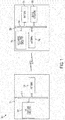
- FIG. 1 is a block diagram illustrating an embodiment of an apparatus for wirelessly charging a wrist-worn device.
- the apparatus 100 for wirelessly charging a wrist-worn device generally comprises a transmitter portion 110, also referred to as a wireless charger, and a receiver portion 150, also referred to as a wireless rechargeable device, or a charge-receiving device.
- the transmitter portion 110 comprises radio frequency (RF) charging circuitry 112 and a transmit antenna 120 connected over a communication bus 114.
- the communication bus 114 can be any physical and/or logical communication infrastructure that allows the connected elements to communication and interoperate.
- the receiver portion 150 comprises radio frequency (RF) charge receiving circuitry 152, a rechargeable power source, such as a battery 156, device circuitry 158 and an antenna 160, connected over a communication bus 154.
- RF radio frequency
- the communication bus 154 can be any physical and/or logical communication infrastructure that allows the connected elements to communication and interoperate.
- the transmit antenna 120 is designed to increase the transfer of charging energy to the receive antenna 160
- the receive antenna 160 is designed to increase the charging energy received from the transmit antenna 120.
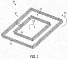
- FIG. 2 is a schematic diagram illustrating an embodiment of the transmit antenna 120 of FIG. 1 .
- the transmit antenna 120 comprises an outer coil 202 and an inner coil 204.
- the outer coil 202 and the inner coil 204 can also be referred to as "inductive” or “induction” coils as they inductively impart charging energy to one or more coils located in a charge-receiving device.
- the outer coil 202 and the inner coil 204 are generally coplanar, and comprise multiple windings.
- the outer coil 202 is wound in a direction 212 opposite the direction 214 of the windings of the inner coil 204.
- the direction of the windings of the outer coil 202 and the inner coil 204 are arbitrary and can be wound in a direction opposite to that shown herein. Winding the outer coil 202 in a direction 212 opposite the direction 214 of the winding of the inner coil 204 confines a magnetic field substantially to an area 210 located between the outer coil 202 and the inner coil 204. As will be described in greater detail below, the area 210 between the outer coil 202 and the inner coil 204 is a location to preferably locate the receive antenna 160 ( FIG. 1 ) to receive increased charging energy from the antenna 120.
- FIG. 3 is a schematic diagram illustrating an example magnetic field generated by the antenna 120 of FIG. 2 .
- a plane 302 is illustrated with respect to the antenna 120. The location of the plane 302 is shown for reference only to illustrate the distribution of a magnetic field 310 that exists in the area 210 located between the outer coil 202 and the inner coil 204.
- the opposite direction of the windings of the outer coil 202 and the inner coil 204 generally confines and focuses the magnetic field 310 to the area 210 because the energy in the magnetic field from each coil is added together in the area 210 and prevents magnetic energy from occurring outside of the outer coil 202 and inside of the inner coil 204 because the energy in the magnetic field from each coil is subtracted from each other in the areas outside of the outer coil 202 and inside of the inner coil 204.
- the outer coil 202 and the inner coil 204 occupy the x-y plane and the magnetic field is generated in the z plane.
- the plane 302 is illustrated as occupying the x-z plane.
- the magnetic field 310 also occupies the y-z plane.
- FIGS. 4A, 4B and 4C are schematic diagrams illustrating an embodiment of the receive antenna 160 of FIG. 1 .
- the receive antenna 160 generally comprises a multiple winding coil 402 that has non-uniform spacing between the windings in different portions of the coil 402. For example, the spacing between the windings in the general areas 410 is narrower than the spacing of the coil windings in the general areas 420.
- Non-uniform spacing of the windings of the coil 402 allows the portion of the coil 402 that is located on an edge of a wristband band to be narrow (e.g., to be able to fit all turns in the edge) and allows the portion of the coil 402 that is located on a large surface of a wristband band to be wider (e.g., to reduce inter-winding coupling).
- the windings in the areas 410 can be located in a plane that is different than the plane in which the windings in the areas 420 are located.
- the windings in the areas 410 can be located in or tilted with respect to a plane defined by the "x" and “y” axes of a Cartesian coordinate system, while the windings in the areas 420 can be located in or tilted with respect to a plane defined by the "x" and “z” or “y” and “z” axes of a Cartesian coordinate system.
- a receive antenna 160 incorporated into a wrist-worn structure can receive charging energy from the transmit antenna 120 described herein.
- the receive antenna 160 generally comprises a "C" shaped configuration, or position, because it is designed to be used within a wrist-worn structure, such as a wristband, that may include a clasp, buckle, snap, or other fastening mechanism that allows it to be opened, placed around a wrist, and then fastened around a wrist.
- a device in which the receive antenna 160 may be incorporated may have any of a loop-shaped configuration, or position, and a C-shaped configuration, or position, and may be configured to be moved between the loop-shaped configuration, or position, and the C-shaped configuration, or position, to accommodate being located in a wristband that can be opened to a "C" shaped position to allow the wristband to be placed around a wrist and then closed to a loop-shaped position when the wristband is secured around a wrist.
- the receive antenna 160 can be generally shaped to fit a number of different applications.
- Non-limiting examples of loop-shaped configurations of the receive antenna 160 include circular, triangular, hexagonal, pentagonal, and any other looped shape. Of course, the receive antenna 160 may have other suitable shapes.
- the non-uniform spacing between windings of the coil 402 and the shape of the coil 402 create what are referred to as one or more "charging planes" located as shown.
- the charging planes 425, 427 and 429 are shown for illustration.
- the non-uniform spacing between windings of the coil 402 allows each charging plane 425, 427 and 429 to be tilted with respect to the planes formed by the major axes x, y and z of the Cartesian coordinate system and to accommodate the shape, configuration and structure of the wrist-worn device into which the coil 402 is incorporated.
- the term "tilted charging plane” is defined as a plane that does not correspond to any plane defined by the major axes in a Cartesian coordinate system.
- the x-y plane, the x-z plane and the y-z plane are planes that are defined by the x, y and z axes in a Cartesian coordinate system.
- a "tilted charging plane” is a plane other than the x-y plane, the x-z plane and the y-z plane.
- FIG. 4C is a schematic diagram illustrating non-tilted charging planes and respective magnetic field vectors.
- the charging plane is the plane that is perpendicular to the vector of the magnetic field. For instance, if the vector of the magnetic field is parallel to the z axis, the charging plane is located in the x-y plane. If the vector of the magnetic field is parallel to the y axis, the charging plane is located in the x-z plane. If the magnetic field is parallel to the x axis, the charging plane is located in the y-z plane.
- a tilted charging plane is a plane other than any of the x-y plane, the x-z plane or the y-z plane, the tilted charging plane is able to couple the magnetic field in the z direction in the example shown in FIGS. 4A and 4B , even though the charging plane is not necessarily in the x-y plane.
- the charging plane is not implemented in the x-y plane due to the limitation of the structure of a band of a wrist-worn device in which the coil is located, particularly, the small area of the edge of the band.
- the charging plane 425 is shown as being tilted with respect to a plane formed by the y-z axis
- the charging plane 427 is shown as being tilted with respect to a plane formed by the x-z axis
- the charging plane 429 is shown as being tilted with respect to a plane formed by the y-z axis.
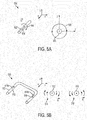
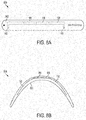
- FIGS. 5A and 5B are a schematic diagrams illustrating a theory of operation of the receive antenna of FIG. 1 .
- a current denoted by an arrow 504 flows in a conductor 502.
- the conductor 502 can be a metallic wire (or other type of conductor) that is used to fabricate the receive antenna 160 and the transmit antenna 120 described above.
- the flow of the current 504 generates a magnetic field "H” 506 that circulates around the conductor 502 according to the "right hand rule.”
- the current 504 flows in the "x" direction and the magnetic field 506 occurs on the y-z plane.
- a conductor 512 is generally "U" shaped and comprises a segment 513 and a segment 515.
- a current 514 is denoted by arrow 514a to denote current flowing in the segment 513 and an arrow 514b to denote current flowing in the segment 515.
- the current 514a generates a magnetic field 516 and the current 514b generates a magnetic field 518. If the conductor 512 is located in the x-y plane, then the "charging plane" is also located in the x-y plane because the charging plane is the plane that is perpendicular to the magnetic field.
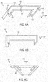
- FIGS. 6A, 6B and 6C are a schematic diagrams illustrating alternative views an embodiment of the receive antenna of FIG. 1 .
- FIG. 6A is a perspective view of the receive antenna 160 of FIGS. 4A and 4B .
- FIG. 6B is a top plan view of the receive antenna 160 of FIGS. 4A and 4B taken in the x-y plane.
- FIG. 6C is a front plan view of the receive antenna 160 of FIGS. 4A and 4B taken in the y-z plane.
- FIG. 7 is a schematic diagram illustrating an embodiment of the transmit antenna 120 and receive antenna 160 of FIG. 1 .
- the receive antenna 160 is located in the area 210 that is between the outer coil 202 and the inner coil 204.
- the charging plane of the antenna 160 is located with respect to the magnetic field 310 in such a way to increase the transfer of charging energy to the receive antenna 160.
- the portions 702, 704 and 706 of the receive antenna 160 are located in planes other than the x-z plane and the y-z plane.
- the portion 702 of the receive antenna 160 forms a plane 712 that is "tilted” with respect to the x-z plane; the portion 704 of the receive antenna 160 forms a plane 714 that is “tilted” with respect to the x-z plane; and the portion 706 of the receive antenna 160 forms a plane 716 that is "tilted” with respect to the y-z plane.
- FIGS. 8A and 8B are schematic diagrams illustrating a wrist-worn device.
- the wrist-worn device 800 comprises a wristband 802 into which an antenna 160, a rechargeable power source, such as a battery 156 and circuitry 158, can be embedded, formed, or otherwise located.
- a rechargeable power source such as a battery 156 and circuitry 158
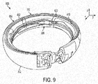
- FIG. 9 is a schematic diagram illustrating the receive antenna of FIG. 1 located in a wristband shaped structure.
- the wristband shaped structure is schematically illustrated as a band 902, including a top edge 904 and an inner surface 906.
- the top edge 904 occupies the x-y plane and the inner surface occupies the x-z and the y-z planes.
- the receive antenna 160 generally comprises a multiple winding coil 402 that has non-uniform spacing between the windings.
- the spacing between the windings in the general area 410 is narrower than the spacing of the coil windings in the general area 420.
- Non-uniform spacing of the windings of the coil 402 allows the portion 410 of the coil 402 that is located on an edge 904 of a wristband band to be narrow (i.e., to be able to fit all turns in the edge) and allows the portion 420 of the coil 402 that is located on a large surface, such as surface 906, of the band 902 to be wider (i.e., to minimize inter-winding coupling).
- the windings in the areas 410 can be located in a plane that is different than the plane in which the windings in the areas 420 are located.
- the windings in the areas 410 can be located in or tilted with respect to a plane defined by the "x" and "y” axes of a Cartesian coordinate system
- the windings in the areas 420 can be located in or tilted with respect to a plane defined by the "x" and "z” or "y” and “z” axes of a Cartesian coordinate system.
- FIG. 10A illustrates an inductive charger circuit 1000A suitable for use with the various embodiments.
- the inductive charger circuit 1000A can be an embodiment of the RF charging circuitry 112 of FIG. 1 .
- the transmitter portion 110 may include a inductive charger circuit 1000A configured to enable the transmitter portion 110 to wirelessly transmit power to a receiver portion 150 by generating a suitable alternating magnetic field.
- the inductive charger circuit 1000A may include a processor 1002 coupled to a memory 1004 and to a power amplifier 1006.
- an alternating current (“AC") input 1014 may be coupled to an AC-to-AC converter 1008 configured to alter the frequency of the input current (e.g., 60 Hz) to a frequency suitable for wirelessly transmitting power to wireless rechargeable devices.
- AC alternating current
- the AC-to-AC converter 1008 may be coupled to a power amplifier 1006 which may be coupled to one or more induction coils 1012a and 1012b, which may be connected in series. Additional induction coils, such as one, two, three, four, or more additional induction coils, may be added in series with induction coils 1012a and 1012b. In the various embodiments, the number of transmit induction coils 1012a, 1012b included in the inductive charger circuit 1000A may be selected to increase the probability that a receive coil of a receiver portion 150 aligns with a transmit coil of the inductive charger circuit 1000A to enable efficient inductive charging.
- the AC input received from the AC input 1014 may be converted to a higher frequency AC current by the AC-to-AC converter 1008, and the higher frequency AC current may be supplied to the power amplifier 1006.
- the amount of current output by the power amplifier 1006 may be adjustable and the processor 1002 may be configured with processor-executable instructions stored in memory 1004 to control the operation of the power amplifier 1006.
- a signal generator may provide an input AC signal with a frequency suitable for inductive charging to the power amplifier 1006 which may receive power from the AC input 1014 and output an amplified AC current to the induction coils 1012a and 1012b. Powered by the higher frequency AC current, the induction coils 1012a and 1012b generate an alternating electromagnetic field.
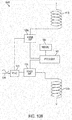
- FIG. 10B illustrates an inductive charger circuit 1000B suitable for use with the various embodiments.
- the inductive charger circuit 1000B can be an embodiment of the RF charging circuitry 112 of FIG. 1 .
- the inductive charger circuit 1000B differs from inductive charger circuit 1000A in that inductive charger circuit 1000B includes one or more additional power amplifiers 1006a connected to induction coil 1012b. Additional induction coils may be added and connected to their own additional power amplifiers. The addition of additional coils and power amplifiers may result in less resistance loss than would be the case from adding induction coils in series as discussed above with reference to FIG. 10A . Moreover, having multiple power amplifiers reduces the power and current rating for each power amplifier, thus simplifying the design for each power amplifier.
- FIG. 11A illustrates an inductive charging circuit including an inductive charging circuit 1100A suitable for use with the various embodiments.
- the inductive charger circuit 1000A can be an embodiment of the RF charge receiving circuitry 152 of FIG. 1 .
- the inductive charging circuit 1100A is configured to enable a wireless charge receiving device associated with a receiver portion 150 to inductively receive power from an inductive charger circuit 1000A or 1000B discussed above with reference to FIGS. 10A and 10B .
- the inductive charging circuit 1100A may include two or more inductive coils 1102a and 1102b connected in series and coupled to a rectifier circuit 1106.
- Such a rectifier circuit 1106 may be any type rectifier, such as a two diode voltage doubler rectifier, a four diode full wave bridge rectifier, etc. Additional inductive coils, such as one, two, three, four, or more additional inductive coils, may be added in series with inductive coils 1102a and 1102b. The number of receive inductive coils included in the inductive charging circuit 1100A may be selected based on the number of surfaces on which a wireless rechargeable device may rest when placed on or near a wireless charger. In operation, the alternating magnetic field from the wireless charger induces an alternating current in the inductive coils 1102a and/or 1102b that passes through the rectifier circuit 1106.
- the output of the rectifier circuit 1106 may be coupled to an EMI filter/buck regulator 1110, which may be coupled to the processor 1118.
- the processor 1118 may be configured with processor-executable instructions to control the operation of the EMI filter/buck regulator 1110.
- the processor 1118 may be coupled to a memory 1120.
- the output of the EMI filter/buck regulator 1110 may be coupled to a capacitor 1112 and the output of the capacitor 1112 may be coupled to a battery 1114.
- the battery 1114 may be coupled to a battery charge sensor 1116 that may be coupled to the processor 1118.
- the battery charge sensor 1116 may output indications of measurements of the battery's 1114 charge to the processor 1118, which the processor may use to regulate power applied to the battery 1114 to avoid overcharging.
- the inductive coils 1102a and/or 1102b generate an alternating electrical current that the rectifier circuit 1106 may rectify into direct current (DC) that the EMI filter/buck regulator 1110 may filter and boost the current's voltage.
- the output of the EMI filter/buck regulator 1110 may be received by the capacitor 1112 that stores electrical energy.
- current drawn from the capacitor may be used to charge the battery 1114.
- the battery charge sensor 1116 may enable the processor 1118 to monitor the battery 1114 charge level and determine when the battery is fully charged. Additionally, the battery charge sensor 1116 may enable the processor 1118 to determine a rate of charge for the battery 1114.
- FIG. 11B illustrates an inductive charging circuit 1100B suitable for use with the various embodiments.
- the inductive charging circuit 1100B illustrated in FIG. 11B differs from the inductive charging circuit 1100A illustrated in FIG. 11A in that the inductive charging circuit 1100B includes one or more additional rectifier circuit 1106a connected to a second induction coil 1102b. Additional induction coils may be added connected to their own additional rectifier circuits. The addition of additional induction coils and rectifier circuits may result in less resistance loss than adding induction coils in series as discussed above with reference to FIG. 11A .
- FIGS. 12A through 12F illustrate various elements of an embodiment of a wireless charging system according to the invention.
- FIG. 12A is a top view of a wireless charger 1208.
- the wireless charger 1208 may include inductive transmit coils 1202 and 1204.
- the inductive transmit coils 1202 and 1204 may be embedded in a charging surface 1210 of the wireless charger 1208.
- the charging surface 1210 may include a graphic guide to assist a user in aligning the wireless rechargeable device 1252 (described with more detail below with reference to FIG. 12C ) on the wireless charger 1208.
- the inductive transmit coils 1202 and 1204 may be low profile coils using American Wire Gauge 30 wires (approx. 0.26mm diameter), for example, or other coils having other suitable properties.
- the wireless charger 1208 may include an inductive charge circuit 1206 to which the inductive transmit coils 1202 and 1204 are electrically connected.
- the inductive transmit coils 1202 and 1204 are connected in series to the inductive charge circuit 1206.
- the inductive transmit coils 1202 and 1204 may not be connected in series, and instead each inductive transmit coil 1202 and 1204 may be connected to a separate power amplifier on the inductive charger circuit 1206.
- the wireless charger 1208 may include the packaging in which the wireless rechargeable device 1252 (described with more detail below with reference to FIG. 12C ) may be sold.
- the inductive transmit coils 1202 and inductive charger circuit 1206, and charging surface 1210 may be integrated into the case in which the wireless rechargeable device 1252 is sold.
- the wireless charger 1208 may include a graphic guide to assist a user in aligning the wireless rechargeable device on a wireless charger surface.
- the wireless charger 1208 may include a LED indicator that may indicate information.
- a blinking LED may indicate a power mode, such as a low power beacon mode, and a continuously illuminated LED may indicate that the charger 1208 is charging a wireless rechargeable device.
- FIG. 12B is a bottom view of the wireless charger 1208 showing the inductive transmit coils 1202 and 1204 connected to the inductive charging circuit 1206 and the back of the charging surface 1210.
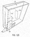
- FIG. 12C is a perspective view of an embodiment of a wireless rechargeable device 1252.
- the wireless rechargeable device 1252 may be configured to rest on at least one, preferably at least two of its surfaces.
- the wireless rechargeable device 1252 may be a wrist watch and may be configured to rest on a first side of the band and a second side of the band depending on which it is laid down by a user. While illustrated as having two surfaces on which it may rest, the wireless rechargeable device 1252 may be configured to rest on more than two surfaces.
- the wireless rechargeable device 1252 On a first of the surfaces on which it is configured to rest, the wireless rechargeable device 1252 may include a first inductive receiver coil 1254.
- the wireless rechargeable device 1252 may include a second inductive receiver coil 1256.
- the inductive receiver coils 1254 and 1256 may be connected to an inductive charging circuit 1258 as described above.
- the inductive charging circuit 1258 may measure 10 mm by 10 mm.
- the inductive receiver coils 1254 and 1256 may be connected in series to the inductive charging circuit 1258.
- the coils may be independent of each other, and the inductive charging circuit 1258 may include a rectifier circuit for each inductive receiver coil 1254 and 1256.
- the wireless rechargeable device may include an LED to indicate that the wireless rechargeable device 1252 is charging.
- FIG. 12D illustrates the wireless rechargeable device in the opposite orientation resting on its first surface with the second inductive receiver coil 1256 oriented up and the first inductive receiver coil 1254 oriented down.
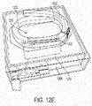
- FIG. 12E shows the wireless rechargeable device 1252 placed on the wireless charger 1208 in a charging configuration.
- the wireless rechargeable device 1252 is placed on the charging surface 1210 with the first surface of the wireless rechargeable device 1252 pointed down.
- the wireless rechargeable device 1252 is placed on the charging surface 1210 of the wireless charger 1208, while all coils may not align to enable power to be wirelessly transmitted (e.g., inductive receiver coil 1256 may not align with a transmit coil and inductive transmitter coil 1202 may not align with a receiver coil), the probability that one receiver coil and one transmit coil (e.g., inductive receiver coil 1254 and inductive transmitter coil 1204) will align to wirelessly transmit power from the wireless charger to the wireless rechargeable device is increased.
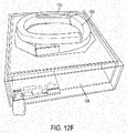
- FIG. 12F illustrates another placement of the wireless rechargeable device 1252 on the wireless charge 1208 that may align different receiver and transmit coils, thereby enabling wireless power transmission.
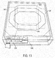
- FIG. 13 illustrates a wireless charger (i.e., transmitter portion) 1306 of a wireless charging system according to another embodiment.
- the wireless charging system in which the wireless charger 1306 is included may be similar to the wireless charging system discussed above with reference to FIGS. 12A through 12F above, except that the wireless charger 1306 may include two additional inductive transmit coils 1302 and 1304. In this manner, additional orientations of the wireless charger 1306 and the wireless rechargeable device 1252 may enable wireless transmission of power.
- the functions described may be implemented in hardware, software, firmware, or any combination thereof. If implemented in software, the functions may be stored on or transmitted as one or more instructions or code on a computer-readable medium.
- Computer-readable media include both computer storage media and communication media including any medium that facilitates transfer of a computer program from one place to another.
- a storage media may be any available media that may be accessed by a computer.
- such computer-readable media may comprise RAM, ROM, EEPROM, CD-ROM or other optical disk storage, magnetic disk storage or other magnetic storage devices, or any other medium that may be used to carry or store desired program code in the form of instructions or data structures and that may be accessed by a computer.
- any connection is properly termed a computer-readable medium.
- the software is transmitted from a website, server, or other remote source using a coaxial cable, fiber optic cable, twisted pair, digital subscriber line ("DSL"), or wireless technologies such as infrared, radio, and microwave
- coaxial cable, fiber optic cable, twisted pair, DSL, or wireless technologies such as infrared, radio, and microwave are included in the definition of medium.
- Disk and disc includes compact disc (“CD”), laser disc, optical disc, digital versatile disc (“DVD”), floppy disk and Blu-Ray disc where disks usually reproduce data magnetically, while discs reproduce data optically with lasers. Combinations of the above should also be included within the scope of computer-readable media.
Landscapes
- Engineering & Computer Science (AREA)
- Power Engineering (AREA)
- Computer Networks & Wireless Communication (AREA)
- Physics & Mathematics (AREA)
- General Physics & Mathematics (AREA)
- Charge And Discharge Circuits For Batteries Or The Like (AREA)
- Coils Of Transformers For General Uses (AREA)
Applications Claiming Priority (5)
| Application Number | Priority Date | Filing Date | Title |
|---|---|---|---|
| US201261730492P | 2012-11-27 | 2012-11-27 | |
| US201261747185P | 2012-12-28 | 2012-12-28 | |
| US13/802,595 US9362776B2 (en) | 2012-11-27 | 2013-03-13 | Wireless charging systems and methods |
| PCT/US2013/071600 WO2014085291A2 (en) | 2012-11-27 | 2013-11-25 | Wireless charging systems and methods |
| EP13803378.2A EP2926351B1 (en) | 2012-11-27 | 2013-11-25 | Wireless charging system for a wrist-worn device |
Related Parent Applications (2)
| Application Number | Title | Priority Date | Filing Date |
|---|---|---|---|
| EP13803378.2A Division-Into EP2926351B1 (en) | 2012-11-27 | 2013-11-25 | Wireless charging system for a wrist-worn device |
| EP13803378.2A Division EP2926351B1 (en) | 2012-11-27 | 2013-11-25 | Wireless charging system for a wrist-worn device |
Publications (2)
| Publication Number | Publication Date |
|---|---|
| EP3145051A1 EP3145051A1 (en) | 2017-03-22 |
| EP3145051B1 true EP3145051B1 (en) | 2019-05-15 |
Family
ID=50771980
Family Applications (2)
| Application Number | Title | Priority Date | Filing Date |
|---|---|---|---|
| EP16190225.9A Not-in-force EP3145051B1 (en) | 2012-11-27 | 2013-11-25 | Wireless charging systems and methods |
| EP13803378.2A Active EP2926351B1 (en) | 2012-11-27 | 2013-11-25 | Wireless charging system for a wrist-worn device |
Family Applications After (1)
| Application Number | Title | Priority Date | Filing Date |
|---|---|---|---|
| EP13803378.2A Active EP2926351B1 (en) | 2012-11-27 | 2013-11-25 | Wireless charging system for a wrist-worn device |
Country Status (7)
| Country | Link |
|---|---|
| US (1) | US9362776B2 (enExample) |
| EP (2) | EP3145051B1 (enExample) |
| JP (1) | JP6312694B2 (enExample) |
| KR (1) | KR102137852B1 (enExample) |
| CN (1) | CN104813420B (enExample) |
| TW (1) | TWI547059B (enExample) |
| WO (1) | WO2014085291A2 (enExample) |
Cited By (1)
| Publication number | Priority date | Publication date | Assignee | Title |
|---|---|---|---|---|
| EP3910751A1 (en) * | 2020-05-11 | 2021-11-17 | GE Precision Healthcare LLC | Methods and systems for wirelessly charging digital x-ray detectors |
Families Citing this family (269)
| Publication number | Priority date | Publication date | Assignee | Title |
|---|---|---|---|---|
| EP3906842A1 (en) | 2011-07-26 | 2021-11-10 | Glysens Incorporated | Tissue implantable sensor with hermetically sealed housing |
| US9859797B1 (en) | 2014-05-07 | 2018-01-02 | Energous Corporation | Synchronous rectifier design for wireless power receiver |
| US10211674B1 (en) | 2013-06-12 | 2019-02-19 | Energous Corporation | Wireless charging using selected reflectors |
| US9882427B2 (en) | 2013-05-10 | 2018-01-30 | Energous Corporation | Wireless power delivery using a base station to control operations of a plurality of wireless power transmitters |
| US9893555B1 (en) | 2013-10-10 | 2018-02-13 | Energous Corporation | Wireless charging of tools using a toolbox transmitter |
| US10063106B2 (en) | 2014-05-23 | 2018-08-28 | Energous Corporation | System and method for a self-system analysis in a wireless power transmission network |
| US10128699B2 (en) | 2014-07-14 | 2018-11-13 | Energous Corporation | Systems and methods of providing wireless power using receiver device sensor inputs |
| US20140008993A1 (en) | 2012-07-06 | 2014-01-09 | DvineWave Inc. | Methodology for pocket-forming |
| US9824815B2 (en) | 2013-05-10 | 2017-11-21 | Energous Corporation | Wireless charging and powering of healthcare gadgets and sensors |
| US10291066B1 (en) | 2014-05-07 | 2019-05-14 | Energous Corporation | Power transmission control systems and methods |
| US9923386B1 (en) | 2012-07-06 | 2018-03-20 | Energous Corporation | Systems and methods for wireless power transmission by modifying a number of antenna elements used to transmit power waves to a receiver |
| US9847679B2 (en) | 2014-05-07 | 2017-12-19 | Energous Corporation | System and method for controlling communication between wireless power transmitter managers |
| US9859757B1 (en) | 2013-07-25 | 2018-01-02 | Energous Corporation | Antenna tile arrangements in electronic device enclosures |
| US10193396B1 (en) | 2014-05-07 | 2019-01-29 | Energous Corporation | Cluster management of transmitters in a wireless power transmission system |
| US9912199B2 (en) | 2012-07-06 | 2018-03-06 | Energous Corporation | Receivers for wireless power transmission |
| US10103582B2 (en) | 2012-07-06 | 2018-10-16 | Energous Corporation | Transmitters for wireless power transmission |
| US10050462B1 (en) | 2013-08-06 | 2018-08-14 | Energous Corporation | Social power sharing for mobile devices based on pocket-forming |
| US10141768B2 (en) | 2013-06-03 | 2018-11-27 | Energous Corporation | Systems and methods for maximizing wireless power transfer efficiency by instructing a user to change a receiver device's position |
| US9806564B2 (en) | 2014-05-07 | 2017-10-31 | Energous Corporation | Integrated rectifier and boost converter for wireless power transmission |
| US9843201B1 (en) | 2012-07-06 | 2017-12-12 | Energous Corporation | Wireless power transmitter that selects antenna sets for transmitting wireless power to a receiver based on location of the receiver, and methods of use thereof |
| US9991741B1 (en) | 2014-07-14 | 2018-06-05 | Energous Corporation | System for tracking and reporting status and usage information in a wireless power management system |
| US9876394B1 (en) | 2014-05-07 | 2018-01-23 | Energous Corporation | Boost-charger-boost system for enhanced power delivery |
| US9843213B2 (en) | 2013-08-06 | 2017-12-12 | Energous Corporation | Social power sharing for mobile devices based on pocket-forming |
| US9838083B2 (en) | 2014-07-21 | 2017-12-05 | Energous Corporation | Systems and methods for communication with remote management systems |
| US10291055B1 (en) | 2014-12-29 | 2019-05-14 | Energous Corporation | Systems and methods for controlling far-field wireless power transmission based on battery power levels of a receiving device |
| US9887739B2 (en) | 2012-07-06 | 2018-02-06 | Energous Corporation | Systems and methods for wireless power transmission by comparing voltage levels associated with power waves transmitted by antennas of a plurality of antennas of a transmitter to determine appropriate phase adjustments for the power waves |
| US10256657B2 (en) * | 2015-12-24 | 2019-04-09 | Energous Corporation | Antenna having coaxial structure for near field wireless power charging |
| US9859756B2 (en) | 2012-07-06 | 2018-01-02 | Energous Corporation | Transmittersand methods for adjusting wireless power transmission based on information from receivers |
| US10063105B2 (en) | 2013-07-11 | 2018-08-28 | Energous Corporation | Proximity transmitters for wireless power charging systems |
| US10063064B1 (en) | 2014-05-23 | 2018-08-28 | Energous Corporation | System and method for generating a power receiver identifier in a wireless power network |
| US20150326070A1 (en) | 2014-05-07 | 2015-11-12 | Energous Corporation | Methods and Systems for Maximum Power Point Transfer in Receivers |
| US10124754B1 (en) | 2013-07-19 | 2018-11-13 | Energous Corporation | Wireless charging and powering of electronic sensors in a vehicle |
| US9954374B1 (en) | 2014-05-23 | 2018-04-24 | Energous Corporation | System and method for self-system analysis for detecting a fault in a wireless power transmission Network |
| US9882430B1 (en) | 2014-05-07 | 2018-01-30 | Energous Corporation | Cluster management of transmitters in a wireless power transmission system |
| US9853458B1 (en) | 2014-05-07 | 2017-12-26 | Energous Corporation | Systems and methods for device and power receiver pairing |
| US9793758B2 (en) | 2014-05-23 | 2017-10-17 | Energous Corporation | Enhanced transmitter using frequency control for wireless power transmission |
| US10186913B2 (en) | 2012-07-06 | 2019-01-22 | Energous Corporation | System and methods for pocket-forming based on constructive and destructive interferences to power one or more wireless power receivers using a wireless power transmitter including a plurality of antennas |
| US10038337B1 (en) | 2013-09-16 | 2018-07-31 | Energous Corporation | Wireless power supply for rescue devices |
| US9143000B2 (en) | 2012-07-06 | 2015-09-22 | Energous Corporation | Portable wireless charging pad |
| US9939864B1 (en) | 2014-08-21 | 2018-04-10 | Energous Corporation | System and method to control a wireless power transmission system by configuration of wireless power transmission control parameters |
| US10148097B1 (en) | 2013-11-08 | 2018-12-04 | Energous Corporation | Systems and methods for using a predetermined number of communication channels of a wireless power transmitter to communicate with different wireless power receivers |
| US12057715B2 (en) | 2012-07-06 | 2024-08-06 | Energous Corporation | Systems and methods of wirelessly delivering power to a wireless-power receiver device in response to a change of orientation of the wireless-power receiver device |
| US10218227B2 (en) | 2014-05-07 | 2019-02-26 | Energous Corporation | Compact PIFA antenna |
| US10965164B2 (en) | 2012-07-06 | 2021-03-30 | Energous Corporation | Systems and methods of wirelessly delivering power to a receiver device |
| US9438045B1 (en) | 2013-05-10 | 2016-09-06 | Energous Corporation | Methods and systems for maximum power point transfer in receivers |
| US10243414B1 (en) | 2014-05-07 | 2019-03-26 | Energous Corporation | Wearable device with wireless power and payload receiver |
| US10211680B2 (en) | 2013-07-19 | 2019-02-19 | Energous Corporation | Method for 3 dimensional pocket-forming |
| US9871398B1 (en) | 2013-07-01 | 2018-01-16 | Energous Corporation | Hybrid charging method for wireless power transmission based on pocket-forming |
| US9853692B1 (en) | 2014-05-23 | 2017-12-26 | Energous Corporation | Systems and methods for wireless power transmission |
| US9893768B2 (en) | 2012-07-06 | 2018-02-13 | Energous Corporation | Methodology for multiple pocket-forming |
| US10090699B1 (en) | 2013-11-01 | 2018-10-02 | Energous Corporation | Wireless powered house |
| US10224982B1 (en) | 2013-07-11 | 2019-03-05 | Energous Corporation | Wireless power transmitters for transmitting wireless power and tracking whether wireless power receivers are within authorized locations |
| US10263432B1 (en) | 2013-06-25 | 2019-04-16 | Energous Corporation | Multi-mode transmitter with an antenna array for delivering wireless power and providing Wi-Fi access |
| US9867062B1 (en) | 2014-07-21 | 2018-01-09 | Energous Corporation | System and methods for using a remote server to authorize a receiving device that has requested wireless power and to determine whether another receiving device should request wireless power in a wireless power transmission system |
| US9899861B1 (en) | 2013-10-10 | 2018-02-20 | Energous Corporation | Wireless charging methods and systems for game controllers, based on pocket-forming |
| US10141791B2 (en) | 2014-05-07 | 2018-11-27 | Energous Corporation | Systems and methods for controlling communications during wireless transmission of power using application programming interfaces |
| US10008889B2 (en) | 2014-08-21 | 2018-06-26 | Energous Corporation | Method for automatically testing the operational status of a wireless power receiver in a wireless power transmission system |
| US10312715B2 (en) | 2015-09-16 | 2019-06-04 | Energous Corporation | Systems and methods for wireless power charging |
| US9876648B2 (en) | 2014-08-21 | 2018-01-23 | Energous Corporation | System and method to control a wireless power transmission system by configuration of wireless power transmission control parameters |
| US9876379B1 (en) | 2013-07-11 | 2018-01-23 | Energous Corporation | Wireless charging and powering of electronic devices in a vehicle |
| US10230266B1 (en) | 2014-02-06 | 2019-03-12 | Energous Corporation | Wireless power receivers that communicate status data indicating wireless power transmission effectiveness with a transmitter using a built-in communications component of a mobile device, and methods of use thereof |
| US9887584B1 (en) | 2014-08-21 | 2018-02-06 | Energous Corporation | Systems and methods for a configuration web service to provide configuration of a wireless power transmitter within a wireless power transmission system |
| US9899873B2 (en) | 2014-05-23 | 2018-02-20 | Energous Corporation | System and method for generating a power receiver identifier in a wireless power network |
| US10199849B1 (en) | 2014-08-21 | 2019-02-05 | Energous Corporation | Method for automatically testing the operational status of a wireless power receiver in a wireless power transmission system |
| US9787103B1 (en) | 2013-08-06 | 2017-10-10 | Energous Corporation | Systems and methods for wirelessly delivering power to electronic devices that are unable to communicate with a transmitter |
| US10075008B1 (en) | 2014-07-14 | 2018-09-11 | Energous Corporation | Systems and methods for manually adjusting when receiving electronic devices are scheduled to receive wirelessly delivered power from a wireless power transmitter in a wireless power network |
| US9831718B2 (en) | 2013-07-25 | 2017-11-28 | Energous Corporation | TV with integrated wireless power transmitter |
| US9825674B1 (en) | 2014-05-23 | 2017-11-21 | Energous Corporation | Enhanced transmitter that selects configurations of antenna elements for performing wireless power transmission and receiving functions |
| US9368020B1 (en) | 2013-05-10 | 2016-06-14 | Energous Corporation | Off-premises alert system and method for wireless power receivers in a wireless power network |
| US10992187B2 (en) | 2012-07-06 | 2021-04-27 | Energous Corporation | System and methods of using electromagnetic waves to wirelessly deliver power to electronic devices |
| US10992185B2 (en) | 2012-07-06 | 2021-04-27 | Energous Corporation | Systems and methods of using electromagnetic waves to wirelessly deliver power to game controllers |
| US10224758B2 (en) | 2013-05-10 | 2019-03-05 | Energous Corporation | Wireless powering of electronic devices with selective delivery range |
| US9893554B2 (en) | 2014-07-14 | 2018-02-13 | Energous Corporation | System and method for providing health safety in a wireless power transmission system |
| US9906065B2 (en) | 2012-07-06 | 2018-02-27 | Energous Corporation | Systems and methods of transmitting power transmission waves based on signals received at first and second subsets of a transmitter's antenna array |
| US10270261B2 (en) | 2015-09-16 | 2019-04-23 | Energous Corporation | Systems and methods of object detection in wireless power charging systems |
| US9948135B2 (en) | 2015-09-22 | 2018-04-17 | Energous Corporation | Systems and methods for identifying sensitive objects in a wireless charging transmission field |
| US9966765B1 (en) | 2013-06-25 | 2018-05-08 | Energous Corporation | Multi-mode transmitter |
| US10439448B2 (en) | 2014-08-21 | 2019-10-08 | Energous Corporation | Systems and methods for automatically testing the communication between wireless power transmitter and wireless power receiver |
| US10090886B1 (en) | 2014-07-14 | 2018-10-02 | Energous Corporation | System and method for enabling automatic charging schedules in a wireless power network to one or more devices |
| US10199835B2 (en) | 2015-12-29 | 2019-02-05 | Energous Corporation | Radar motion detection using stepped frequency in wireless power transmission system |
| US9891669B2 (en) | 2014-08-21 | 2018-02-13 | Energous Corporation | Systems and methods for a configuration web service to provide configuration of a wireless power transmitter within a wireless power transmission system |
| US9941707B1 (en) | 2013-07-19 | 2018-04-10 | Energous Corporation | Home base station for multiple room coverage with multiple transmitters |
| US10381880B2 (en) | 2014-07-21 | 2019-08-13 | Energous Corporation | Integrated antenna structure arrays for wireless power transmission |
| US10206185B2 (en) | 2013-05-10 | 2019-02-12 | Energous Corporation | System and methods for wireless power transmission to an electronic device in accordance with user-defined restrictions |
| US10128693B2 (en) | 2014-07-14 | 2018-11-13 | Energous Corporation | System and method for providing health safety in a wireless power transmission system |
| US10205239B1 (en) | 2014-05-07 | 2019-02-12 | Energous Corporation | Compact PIFA antenna |
| US11502551B2 (en) | 2012-07-06 | 2022-11-15 | Energous Corporation | Wirelessly charging multiple wireless-power receivers using different subsets of an antenna array to focus energy at different locations |
| US9847677B1 (en) | 2013-10-10 | 2017-12-19 | Energous Corporation | Wireless charging and powering of healthcare gadgets and sensors |
| US9252628B2 (en) | 2013-05-10 | 2016-02-02 | Energous Corporation | Laptop computer as a transmitter for wireless charging |
| US9900057B2 (en) | 2012-07-06 | 2018-02-20 | Energous Corporation | Systems and methods for assigning groups of antenas of a wireless power transmitter to different wireless power receivers, and determining effective phases to use for wirelessly transmitting power using the assigned groups of antennas |
| US9973021B2 (en) | 2012-07-06 | 2018-05-15 | Energous Corporation | Receivers for wireless power transmission |
| US10211682B2 (en) | 2014-05-07 | 2019-02-19 | Energous Corporation | Systems and methods for controlling operation of a transmitter of a wireless power network based on user instructions received from an authenticated computing device powered or charged by a receiver of the wireless power network |
| US9941747B2 (en) | 2014-07-14 | 2018-04-10 | Energous Corporation | System and method for manually selecting and deselecting devices to charge in a wireless power network |
| US9124125B2 (en) | 2013-05-10 | 2015-09-01 | Energous Corporation | Wireless power transmission with selective range |
| US9812890B1 (en) | 2013-07-11 | 2017-11-07 | Energous Corporation | Portable wireless charging pad |
| US10223717B1 (en) | 2014-05-23 | 2019-03-05 | Energous Corporation | Systems and methods for payment-based authorization of wireless power transmission service |
| US9941754B2 (en) | 2012-07-06 | 2018-04-10 | Energous Corporation | Wireless power transmission with selective range |
| US10561353B2 (en) | 2016-06-01 | 2020-02-18 | Glysens Incorporated | Biocompatible implantable sensor apparatus and methods |
| US10660550B2 (en) | 2015-12-29 | 2020-05-26 | Glysens Incorporated | Implantable sensor apparatus and methods |
| US9118188B2 (en) * | 2012-12-17 | 2015-08-25 | Intel Corporation | Wireless charging system |
| JP6167395B2 (ja) * | 2013-03-22 | 2017-07-26 | パナソニックIpマネジメント株式会社 | 給電装置 |
| US9537357B2 (en) | 2013-05-10 | 2017-01-03 | Energous Corporation | Wireless sound charging methods and systems for game controllers, based on pocket-forming |
| US9419443B2 (en) | 2013-05-10 | 2016-08-16 | Energous Corporation | Transducer sound arrangement for pocket-forming |
| US9866279B2 (en) | 2013-05-10 | 2018-01-09 | Energous Corporation | Systems and methods for selecting which power transmitter should deliver wireless power to a receiving device in a wireless power delivery network |
| US9819230B2 (en) | 2014-05-07 | 2017-11-14 | Energous Corporation | Enhanced receiver for wireless power transmission |
| US9538382B2 (en) | 2013-05-10 | 2017-01-03 | Energous Corporation | System and method for smart registration of wireless power receivers in a wireless power network |
| JP2014230383A (ja) * | 2013-05-22 | 2014-12-08 | 株式会社東芝 | 電子機器 |
| US10103552B1 (en) | 2013-06-03 | 2018-10-16 | Energous Corporation | Protocols for authenticated wireless power transmission |
| US10003211B1 (en) | 2013-06-17 | 2018-06-19 | Energous Corporation | Battery life of portable electronic devices |
| KR101852940B1 (ko) * | 2013-06-20 | 2018-04-27 | 엘지이노텍 주식회사 | 수신 안테나 및 이를 포함하는 무선 전력 수신 장치 |
| KR101950947B1 (ko) * | 2013-06-27 | 2019-02-21 | 엘지이노텍 주식회사 | 수신 안테나 및 이를 포함하는 무선 전력 수신 장치 |
| US10021523B2 (en) | 2013-07-11 | 2018-07-10 | Energous Corporation | Proximity transmitters for wireless power charging systems |
| US9979440B1 (en) | 2013-07-25 | 2018-05-22 | Energous Corporation | Antenna tile arrangements configured to operate as one functional unit |
| DE102013216753A1 (de) * | 2013-08-23 | 2015-02-26 | Novero Dabendorf Gmbh | Vorrichtung und Verfahren zur kombinierten Signalübertragung oder zur kombinierten Signal- und Energieübertragung |
| KR102025889B1 (ko) * | 2013-11-14 | 2019-09-26 | 주식회사 위츠 | 휴대 단말기와 무선 충전 장치 및 무선 충전 구조 |
| US9384722B2 (en) * | 2014-01-10 | 2016-07-05 | Fishman Transducers, Inc. | Method and device for rechargeable, retrofittable battery pack |
| US10075017B2 (en) | 2014-02-06 | 2018-09-11 | Energous Corporation | External or internal wireless power receiver with spaced-apart antenna elements for charging or powering mobile devices using wirelessly delivered power |
| US9935482B1 (en) | 2014-02-06 | 2018-04-03 | Energous Corporation | Wireless power transmitters that transmit at determined times based on power availability and consumption at a receiving mobile device |
| US10158257B2 (en) | 2014-05-01 | 2018-12-18 | Energous Corporation | System and methods for using sound waves to wirelessly deliver power to electronic devices |
| US9966784B2 (en) | 2014-06-03 | 2018-05-08 | Energous Corporation | Systems and methods for extending battery life of portable electronic devices charged by sound |
| US9973008B1 (en) | 2014-05-07 | 2018-05-15 | Energous Corporation | Wireless power receiver with boost converters directly coupled to a storage element |
| US10170917B1 (en) | 2014-05-07 | 2019-01-01 | Energous Corporation | Systems and methods for managing and controlling a wireless power network by establishing time intervals during which receivers communicate with a transmitter |
| US9800172B1 (en) | 2014-05-07 | 2017-10-24 | Energous Corporation | Integrated rectifier and boost converter for boosting voltage received from wireless power transmission waves |
| US10153645B1 (en) | 2014-05-07 | 2018-12-11 | Energous Corporation | Systems and methods for designating a master power transmitter in a cluster of wireless power transmitters |
| US10153653B1 (en) | 2014-05-07 | 2018-12-11 | Energous Corporation | Systems and methods for using application programming interfaces to control communications between a transmitter and a receiver |
| US9831685B2 (en) * | 2014-05-16 | 2017-11-28 | Samsung Electro-Mechanics Co., Ltd. | Wireless power transmitter |
| US9876536B1 (en) | 2014-05-23 | 2018-01-23 | Energous Corporation | Systems and methods for assigning groups of antennas to transmit wireless power to different wireless power receivers |
| US9583256B2 (en) * | 2014-06-13 | 2017-02-28 | Verily Life Sciences Llc | Three-dimensional wireless charging coil |
| US10068703B1 (en) | 2014-07-21 | 2018-09-04 | Energous Corporation | Integrated miniature PIFA with artificial magnetic conductor metamaterials |
| US10116143B1 (en) | 2014-07-21 | 2018-10-30 | Energous Corporation | Integrated antenna arrays for wireless power transmission |
| US9871301B2 (en) | 2014-07-21 | 2018-01-16 | Energous Corporation | Integrated miniature PIFA with artificial magnetic conductor metamaterials |
| US9917477B1 (en) | 2014-08-21 | 2018-03-13 | Energous Corporation | Systems and methods for automatically testing the communication between power transmitter and wireless receiver |
| US9965009B1 (en) | 2014-08-21 | 2018-05-08 | Energous Corporation | Systems and methods for assigning a power receiver to individual power transmitters based on location of the power receiver |
| JP6378006B2 (ja) * | 2014-08-29 | 2018-08-22 | 東芝テック株式会社 | 電力伝送装置及び送電装置 |
| US9793744B2 (en) | 2014-09-12 | 2017-10-17 | Robert Bosch Tool Corporation | Interface and mounting structure for a wireless charger or intermediate piece |
| US20160094072A1 (en) * | 2014-09-26 | 2016-03-31 | Yuanning Chen | Hybrid energy harvesting device |
| US10404089B2 (en) | 2014-09-29 | 2019-09-03 | Apple Inc. | Inductive charging between electronic devices |
| KR101535048B1 (ko) * | 2014-09-30 | 2015-07-09 | 엘지이노텍 주식회사 | 무선 전력 송신 장치 |
| GB2531507A (en) | 2014-10-14 | 2016-04-27 | Intelligent Energy Ltd | An inductive charger |
| KR102245820B1 (ko) * | 2014-11-04 | 2021-04-28 | 삼성전자주식회사 | 플렉서블 케이블을 구비한 전자 장치 |
| US9614385B2 (en) | 2014-11-14 | 2017-04-04 | Motorola Solutions, Inc. | Apparatus and method for full-orientation over-the-air charging in portable electronic devices |
| US10200087B2 (en) * | 2014-12-23 | 2019-02-05 | Intel Corporation | Wireless power receiving coil along a loop of a device |
| US10122415B2 (en) | 2014-12-27 | 2018-11-06 | Energous Corporation | Systems and methods for assigning a set of antennas of a wireless power transmitter to a wireless power receiver based on a location of the wireless power receiver |
| KR101656260B1 (ko) * | 2015-01-05 | 2016-09-09 | 주식회사 아모센스 | 무선충전용 차폐유닛 및 이를 포함하는 무선전력 충전모듈 |
| US9893535B2 (en) | 2015-02-13 | 2018-02-13 | Energous Corporation | Systems and methods for determining optimal charging positions to maximize efficiency of power received from wirelessly delivered sound wave energy |
| JP6402818B2 (ja) * | 2015-02-20 | 2018-10-10 | 富士通株式会社 | 受電器、及び、電力伝送システム |
| US10122182B2 (en) * | 2015-02-27 | 2018-11-06 | Qualcomm Incorporated | Multi-turn coil on metal backplate |
| US10664020B2 (en) | 2015-04-23 | 2020-05-26 | Semiconductor Energy Laboratory Co., Ltd. | Electronic device |
| US20160322854A1 (en) * | 2015-04-30 | 2016-11-03 | Qualcomm Incorporated | Wearable receive coils for wireless power transfer with no electrical contact |
| CN104865819B (zh) * | 2015-05-11 | 2017-09-01 | 广东小天才科技有限公司 | 一种带有触摸显示屏的多功能手表基座 |
| US10475571B2 (en) * | 2015-05-26 | 2019-11-12 | Amosense Co., Ltd. | Wireless power reception module |
| US9653940B2 (en) * | 2015-06-02 | 2017-05-16 | Voyetra Turtle Beach, Inc. | Headset wireless charging dock |
| CN107836069A (zh) * | 2015-07-09 | 2018-03-23 | 富士通株式会社 | 磁场谐振式馈电装置 |
| JP6531942B2 (ja) * | 2015-07-21 | 2019-06-19 | パナソニックIpマネジメント株式会社 | 送電装置 |
| KR20170024944A (ko) * | 2015-08-26 | 2017-03-08 | 엘지이노텍 주식회사 | 무선 전력 송신 장치 |
| US9906275B2 (en) | 2015-09-15 | 2018-02-27 | Energous Corporation | Identifying receivers in a wireless charging transmission field |
| US10523033B2 (en) | 2015-09-15 | 2019-12-31 | Energous Corporation | Receiver devices configured to determine location within a transmission field |
| US12283828B2 (en) | 2015-09-15 | 2025-04-22 | Energous Corporation | Receiver devices configured to determine location within a transmission field |
| US10008875B1 (en) | 2015-09-16 | 2018-06-26 | Energous Corporation | Wireless power transmitter configured to transmit power waves to a predicted location of a moving wireless power receiver |
| US10158259B1 (en) | 2015-09-16 | 2018-12-18 | Energous Corporation | Systems and methods for identifying receivers in a transmission field by transmitting exploratory power waves towards different segments of a transmission field |
| US10199850B2 (en) | 2015-09-16 | 2019-02-05 | Energous Corporation | Systems and methods for wirelessly transmitting power from a transmitter to a receiver by determining refined locations of the receiver in a segmented transmission field associated with the transmitter |
| US9941752B2 (en) | 2015-09-16 | 2018-04-10 | Energous Corporation | Systems and methods of object detection in wireless power charging systems |
| US10778041B2 (en) | 2015-09-16 | 2020-09-15 | Energous Corporation | Systems and methods for generating power waves in a wireless power transmission system |
| US11710321B2 (en) * | 2015-09-16 | 2023-07-25 | Energous Corporation | Systems and methods of object detection in wireless power charging systems |
| US10186893B2 (en) | 2015-09-16 | 2019-01-22 | Energous Corporation | Systems and methods for real time or near real time wireless communications between a wireless power transmitter and a wireless power receiver |
| US9871387B1 (en) | 2015-09-16 | 2018-01-16 | Energous Corporation | Systems and methods of object detection using one or more video cameras in wireless power charging systems |
| US10211685B2 (en) | 2015-09-16 | 2019-02-19 | Energous Corporation | Systems and methods for real or near real time wireless communications between a wireless power transmitter and a wireless power receiver |
| US9893538B1 (en) | 2015-09-16 | 2018-02-13 | Energous Corporation | Systems and methods of object detection in wireless power charging systems |
| US10135295B2 (en) | 2015-09-22 | 2018-11-20 | Energous Corporation | Systems and methods for nullifying energy levels for wireless power transmission waves |
| US10020678B1 (en) | 2015-09-22 | 2018-07-10 | Energous Corporation | Systems and methods for selecting antennas to generate and transmit power transmission waves |
| US10050470B1 (en) | 2015-09-22 | 2018-08-14 | Energous Corporation | Wireless power transmission device having antennas oriented in three dimensions |
| US10027168B2 (en) | 2015-09-22 | 2018-07-17 | Energous Corporation | Systems and methods for generating and transmitting wireless power transmission waves using antennas having a spacing that is selected by the transmitter |
| US10153660B1 (en) | 2015-09-22 | 2018-12-11 | Energous Corporation | Systems and methods for preconfiguring sensor data for wireless charging systems |
| US10033222B1 (en) | 2015-09-22 | 2018-07-24 | Energous Corporation | Systems and methods for determining and generating a waveform for wireless power transmission waves |
| US10135294B1 (en) | 2015-09-22 | 2018-11-20 | Energous Corporation | Systems and methods for preconfiguring transmission devices for power wave transmissions based on location data of one or more receivers |
| US10128686B1 (en) | 2015-09-22 | 2018-11-13 | Energous Corporation | Systems and methods for identifying receiver locations using sensor technologies |
| CN105262241A (zh) * | 2015-09-30 | 2016-01-20 | 武汉大学 | 适用于电动汽车无线供电系统的发射线圈 |
| JP6120116B2 (ja) | 2015-10-02 | 2017-04-26 | パナソニックIpマネジメント株式会社 | 無線電力伝送システム |
| US10784030B2 (en) * | 2015-10-05 | 2020-09-22 | Amogreentech Co., Ltd. | Magnetic sheet, module comprising same, and portable device comprising same |
| US10734717B2 (en) | 2015-10-13 | 2020-08-04 | Energous Corporation | 3D ceramic mold antenna |
| US10333332B1 (en) | 2015-10-13 | 2019-06-25 | Energous Corporation | Cross-polarized dipole antenna |
| US9853485B2 (en) | 2015-10-28 | 2017-12-26 | Energous Corporation | Antenna for wireless charging systems |
| US9899744B1 (en) | 2015-10-28 | 2018-02-20 | Energous Corporation | Antenna for wireless charging systems |
| US10135112B1 (en) | 2015-11-02 | 2018-11-20 | Energous Corporation | 3D antenna mount |
| US10027180B1 (en) | 2015-11-02 | 2018-07-17 | Energous Corporation | 3D triple linear antenna that acts as heat sink |
| US10063108B1 (en) | 2015-11-02 | 2018-08-28 | Energous Corporation | Stamped three-dimensional antenna |
| CN105471025A (zh) * | 2015-12-08 | 2016-04-06 | 联想(北京)有限公司 | 一种可形变电子设备和无线充电系统 |
| CN106877908A (zh) * | 2015-12-11 | 2017-06-20 | 速码波科技股份有限公司 | 信号传输装置 |
| US10320446B2 (en) | 2015-12-24 | 2019-06-11 | Energous Corporation | Miniaturized highly-efficient designs for near-field power transfer system |
| US10079515B2 (en) | 2016-12-12 | 2018-09-18 | Energous Corporation | Near-field RF charging pad with multi-band antenna element with adaptive loading to efficiently charge an electronic device at any position on the pad |
| US10545907B2 (en) * | 2015-12-24 | 2020-01-28 | Intel Corporation | Adjustable power delivery scheme for universal serial bus |
| US11863001B2 (en) | 2015-12-24 | 2024-01-02 | Energous Corporation | Near-field antenna for wireless power transmission with antenna elements that follow meandering patterns |
| US10038332B1 (en) | 2015-12-24 | 2018-07-31 | Energous Corporation | Systems and methods of wireless power charging through multiple receiving devices |
| US10027159B2 (en) | 2015-12-24 | 2018-07-17 | Energous Corporation | Antenna for transmitting wireless power signals |
| US10256677B2 (en) | 2016-12-12 | 2019-04-09 | Energous Corporation | Near-field RF charging pad with adaptive loading to efficiently charge an electronic device at any position on the pad |
| US10135286B2 (en) | 2015-12-24 | 2018-11-20 | Energous Corporation | Near field transmitters for wireless power charging of an electronic device by leaking RF energy through an aperture offset from a patch antenna |
| US10008886B2 (en) | 2015-12-29 | 2018-06-26 | Energous Corporation | Modular antennas with heat sinks in wireless power transmission systems |
| ES1151333Y (es) * | 2016-01-26 | 2016-10-27 | Larburu Santos Francisco Laserna | Mesa inductiva |
| US20170229913A1 (en) * | 2016-02-08 | 2017-08-10 | Qualcomm Incorporated | Wireless power transfer in wearable devices |
| US20170237267A1 (en) * | 2016-02-12 | 2017-08-17 | Qualcomm Incorporated | Wireless power receiving element with capacitive coupling |
| JP6747845B2 (ja) * | 2016-03-30 | 2020-08-26 | 三洋化成工業株式会社 | 腕装着型電子機器及び非接触充電システム |
| US10638962B2 (en) | 2016-06-29 | 2020-05-05 | Glysens Incorporated | Bio-adaptable implantable sensor apparatus and methods |
| KR102589290B1 (ko) | 2016-06-30 | 2023-10-13 | 엘지이노텍 주식회사 | 무선 전력 송신 코일 형상 및 코일의 배치 방법 |
| US10601468B2 (en) | 2016-09-06 | 2020-03-24 | Apple Inc. | Wirelessly charged devices |
| DE102016219491A1 (de) * | 2016-10-07 | 2018-04-12 | Bayerische Motoren Werke Aktiengesellschaft | Spuleneinheit zum induktiven Laden eines Fahrzeuges |
| US10923954B2 (en) | 2016-11-03 | 2021-02-16 | Energous Corporation | Wireless power receiver with a synchronous rectifier |
| CN110535252A (zh) | 2016-12-12 | 2019-12-03 | 艾诺格思公司 | 用于管理发射设备的操作的集成电路和射频发射设备 |
| US10439442B2 (en) | 2017-01-24 | 2019-10-08 | Energous Corporation | Microstrip antennas for wireless power transmitters |
| US10389161B2 (en) | 2017-03-15 | 2019-08-20 | Energous Corporation | Surface mount dielectric antennas for wireless power transmitters |
| US10680319B2 (en) | 2017-01-06 | 2020-06-09 | Energous Corporation | Devices and methods for reducing mutual coupling effects in wireless power transmission systems |
| US20180262059A1 (en) * | 2017-02-03 | 2018-09-13 | AMI Research & Development, LLC | Electric vehicle charging via rf loops to avoid need for precise alignment with wireless charging equipment |
| US10421534B2 (en) * | 2017-02-07 | 2019-09-24 | Goodrich Corporaiton | Systems and methods for variable gap wireless power and communication |
| DE102017202158A1 (de) * | 2017-02-10 | 2018-08-16 | Robert Bosch Gmbh | Ladevorrichtung und Verfahren zum Betrieb einer Ladevorrichtung |
| KR102624303B1 (ko) * | 2017-02-16 | 2024-01-15 | 주식회사 위츠 | 무선 전력 송신 장치 |
| US11011942B2 (en) | 2017-03-30 | 2021-05-18 | Energous Corporation | Flat antennas having two or more resonant frequencies for use in wireless power transmission systems |
| CN110574231B (zh) * | 2017-03-31 | 2021-08-17 | 阿莫技术有限公司 | 环形天线及具有该环形天线的耳机模块 |
| US10511097B2 (en) | 2017-05-12 | 2019-12-17 | Energous Corporation | Near-field antennas for accumulating energy at a near-field distance with minimal far-field gain |
| US12074452B2 (en) | 2017-05-16 | 2024-08-27 | Wireless Electrical Grid Lan, Wigl Inc. | Networked wireless charging system |
| US11462949B2 (en) | 2017-05-16 | 2022-10-04 | Wireless electrical Grid LAN, WiGL Inc | Wireless charging method and system |
| US12074460B2 (en) | 2017-05-16 | 2024-08-27 | Wireless Electrical Grid Lan, Wigl Inc. | Rechargeable wireless power bank and method of using |
| CN107370243B (zh) * | 2017-06-20 | 2019-06-07 | 华为技术有限公司 | 一种终端无线充电接收装置、发射装置与无线充电系统 |
| US10848853B2 (en) | 2017-06-23 | 2020-11-24 | Energous Corporation | Systems, methods, and devices for utilizing a wire of a sound-producing device as an antenna for receipt of wirelessly delivered power |
| US10638979B2 (en) | 2017-07-10 | 2020-05-05 | Glysens Incorporated | Analyte sensor data evaluation and error reduction apparatus and methods |
| US10855110B2 (en) | 2017-09-06 | 2020-12-01 | Apple Inc. | Antenna integration for portable electronic devices having wireless charging receiver systems |
| US11426091B2 (en) | 2017-09-06 | 2022-08-30 | Apple Inc. | Film coatings as electrically conductive pathways |
| US10381881B2 (en) | 2017-09-06 | 2019-08-13 | Apple Inc. | Architecture of portable electronic devices with wireless charging receiver systems |
| US10122219B1 (en) | 2017-10-10 | 2018-11-06 | Energous Corporation | Systems, methods, and devices for using a battery as a antenna for receiving wirelessly delivered power from radio frequency power waves |
| US11342798B2 (en) | 2017-10-30 | 2022-05-24 | Energous Corporation | Systems and methods for managing coexistence of wireless-power signals and data signals operating in a same frequency band |
| US10554796B2 (en) * | 2017-11-01 | 2020-02-04 | Western Digital Technologies, Inc. | Memory station for automatically backing up data and charging mobile devices |
| US11278668B2 (en) | 2017-12-22 | 2022-03-22 | Glysens Incorporated | Analyte sensor and medicant delivery data evaluation and error reduction apparatus and methods |
| US11255839B2 (en) | 2018-01-04 | 2022-02-22 | Glysens Incorporated | Apparatus and methods for analyte sensor mismatch correction |
| US10806676B2 (en) * | 2018-01-30 | 2020-10-20 | Omnicell, Inc. | Relay tray |
| US10615647B2 (en) | 2018-02-02 | 2020-04-07 | Energous Corporation | Systems and methods for detecting wireless power receivers and other objects at a near-field charging pad |
| CN110277627A (zh) * | 2018-03-13 | 2019-09-24 | 泰科电子(上海)有限公司 | 无线供电设备 |
| US11159057B2 (en) | 2018-03-14 | 2021-10-26 | Energous Corporation | Loop antennas with selectively-activated feeds to control propagation patterns of wireless power signals |
| US11515732B2 (en) | 2018-06-25 | 2022-11-29 | Energous Corporation | Power wave transmission techniques to focus wirelessly delivered power at a receiving device |
| US10821292B2 (en) * | 2018-06-28 | 2020-11-03 | Medtronic, Inc. | Multi-axis coil for implantable medical device |
| CN108899948A (zh) * | 2018-07-06 | 2018-11-27 | 李东方 | 一种无线充电箱 |
| CN110707828A (zh) * | 2018-07-09 | 2020-01-17 | 中兴通讯股份有限公司 | 无线充电接收装置、无线充电的实现方法和移动终端 |
| EP3618227B1 (en) * | 2018-08-29 | 2024-01-03 | Oticon A/s | Wireless charging of multiple rechargeable devices |
| US11314281B2 (en) * | 2018-09-10 | 2022-04-26 | Apple Inc. | Display system |
| US11437735B2 (en) | 2018-11-14 | 2022-09-06 | Energous Corporation | Systems for receiving electromagnetic energy using antennas that are minimally affected by the presence of the human body |
| JP2022523022A (ja) | 2019-01-28 | 2022-04-21 | エナージャス コーポレイション | 無線送電のための小型アンテナ用のシステム及び方法 |
| KR20210123329A (ko) | 2019-02-06 | 2021-10-13 | 에너저스 코포레이션 | 안테나 어레이에 있어서의 개별 안테나들에 이용하기 위해 최적 위상을 추정하는 시스템 및 방법 |
| CN109795354B (zh) * | 2019-03-07 | 2023-08-15 | 暨南大学 | 一种车载无线充电线圈的自动对准装置及方法 |
| US12155231B2 (en) | 2019-04-09 | 2024-11-26 | Energous Corporation | Asymmetric spiral antennas for wireless power transmission and reception |
| WO2021055901A1 (en) | 2019-09-20 | 2021-03-25 | Energous Corporation | Asymmetric spiral antennas with parasitic elements for wireless power transmission |
| US11411441B2 (en) | 2019-09-20 | 2022-08-09 | Energous Corporation | Systems and methods of protecting wireless power receivers using multiple rectifiers and establishing in-band communications using multiple rectifiers |
| CN114731061A (zh) | 2019-09-20 | 2022-07-08 | 艾诺格思公司 | 使用无线功率发射系统中的功率放大器控制器集成电路来分类和检测异物 |
| US11381118B2 (en) | 2019-09-20 | 2022-07-05 | Energous Corporation | Systems and methods for machine learning based foreign object detection for wireless power transmission |
| WO2021055898A1 (en) | 2019-09-20 | 2021-03-25 | Energous Corporation | Systems and methods for machine learning based foreign object detection for wireless power transmission |
| WO2021119483A1 (en) | 2019-12-13 | 2021-06-17 | Energous Corporation | Charging pad with guiding contours to align an electronic device on the charging pad and efficiently transfer near-field radio-frequency energy to the electronic device |
| CN111049281A (zh) * | 2019-12-23 | 2020-04-21 | 国网江西省电力有限公司电力科学研究院 | 一种可自由定位的无线充电系统 |
| US10985617B1 (en) | 2019-12-31 | 2021-04-20 | Energous Corporation | System for wirelessly transmitting energy at a near-field distance without using beam-forming control |
| KR102781700B1 (ko) | 2020-03-19 | 2025-03-18 | 삼성전자 주식회사 | 전자 장치의 화면을 홀로그램으로 표시하는 거치 장치 |
| TWI743727B (zh) * | 2020-03-31 | 2021-10-21 | 國美科技有限公司 | 無線供電方法 |
| US11799324B2 (en) | 2020-04-13 | 2023-10-24 | Energous Corporation | Wireless-power transmitting device for creating a uniform near-field charging area |
| US11469629B2 (en) | 2020-08-12 | 2022-10-11 | Energous Corporation | Systems and methods for secure wireless transmission of power using unidirectional communication signals from a wireless-power-receiving device |
| US11456623B2 (en) | 2020-11-04 | 2022-09-27 | Lagree Technologies, Inc. | Wireless power system for an exercise machine |
| US12306285B2 (en) | 2020-12-01 | 2025-05-20 | Energous Corporation | Systems and methods for using one or more sensors to detect and classify objects in a keep-out zone of a wireless-power transmission field, and antennas with integrated sensor arrangements |
| CN112953038B (zh) * | 2021-03-25 | 2023-06-16 | 国网河北省电力有限公司雄安新区供电公司 | 电动汽车静态无线充电系统及其电磁耦合机构和设计方法 |
| US20240178704A1 (en) * | 2021-03-25 | 2024-05-30 | Indian Institute Of Technology Ropar | Dual-mode antenna with non-uniform coil array for wireless power transmission and method thereof |
| CN115411844A (zh) * | 2021-05-27 | 2022-11-29 | 华为技术有限公司 | 一种无线充电系统、方法和装置 |
| CN115020077B (zh) * | 2021-12-01 | 2023-05-02 | 荣耀终端有限公司 | 无线充电线圈、电子设备及天线 |
| US11916398B2 (en) | 2021-12-29 | 2024-02-27 | Energous Corporation | Small form-factor devices with integrated and modular harvesting receivers, and shelving-mounted wireless-power transmitters for use therewith |
| US20250233453A1 (en) * | 2022-04-07 | 2025-07-17 | Scanstrut Limited | Wireless power system for portable electrical devices on marine vessels and land vessels |
| US12142939B2 (en) | 2022-05-13 | 2024-11-12 | Energous Corporation | Integrated wireless-power-transmission platform designed to operate in multiple bands, and multi-band antennas for use therewith |
| CN115021421A (zh) * | 2022-06-21 | 2022-09-06 | 西安电掣风云智能科技有限公司 | 空心谐振立体线圈、无线电能传输用耦合线圈及机械转轴用无线电能传输装置 |
| WO2024197688A1 (en) * | 2023-03-30 | 2024-10-03 | Renesas Electronics America Inc. | Split planar coil for wireless power transfer |
Family Cites Families (32)
| Publication number | Priority date | Publication date | Assignee | Title |
|---|---|---|---|---|
| GB2201266A (en) | 1986-12-23 | 1988-08-24 | Upperpace Limited | A radio paging watch |
| DE3851664T2 (de) * | 1987-07-10 | 1995-02-16 | Seiko Epson Corp | Ladevorrichtung für elektronisches Gerät. |
| JPH03198532A (ja) * | 1989-12-27 | 1991-08-29 | Omron Corp | ブレスレット型非接触記録媒体 |
| CA2292194C (en) * | 1998-12-22 | 2010-02-16 | Eta Sa Fabriques D'ebauches | Wristwatch with capacitive coupling |
| US6127799A (en) | 1999-05-14 | 2000-10-03 | Gte Internetworking Incorporated | Method and apparatus for wireless powering and recharging |
| EP1303022A1 (fr) | 2001-10-12 | 2003-04-16 | The Swatch Group Management Services AG | Chargeur inductif pour objet portatif électronique tel que, notamment, une pièce d'horlogerie du type montre-bracelet |
| EP1315051A1 (fr) | 2001-11-26 | 2003-05-28 | ETA SA Manufacture Horlogère Suisse | Objet électronique de petites dimensions susceptible d'être porté au poignet |
| CH713523B1 (fr) * | 2001-11-26 | 2018-09-14 | Ebauchesfabrik Eta Ag | Objet électronique portatif tel qu'une pièce d'horlogerie susceptible d'être porté au poignet. |
| GB2388715B (en) | 2002-05-13 | 2005-08-03 | Splashpower Ltd | Improvements relating to the transfer of electromagnetic power |
| WO2004038888A2 (en) | 2002-10-28 | 2004-05-06 | Splashpower Limited | Unit and system for contactless power transfer |
| DE60227260D1 (de) * | 2002-10-28 | 2008-08-07 | Eta Sa Mft Horlogere Suisse | Tragbare elektronische Vorrichtung mit einer elektrischen Verbindung in dem Vorrichtungsgehäuse |
| EP1692753A1 (en) * | 2003-12-03 | 2006-08-23 | Koninklijke Philips Electronics N.V. | A garment including an inductive button and buttonhole |
| JP2005278318A (ja) | 2004-03-25 | 2005-10-06 | Seiko Epson Corp | 充電装置、充電装置の制御方法、制御プログラム及び記録媒体 |
| WO2006097870A2 (en) * | 2005-03-14 | 2006-09-21 | Philips Intellectual Property & Standards Gmbh | A system, an inductive powering device, an energizable load and a method of for enabling a wireless power transfer |
| JP2007130033A (ja) * | 2005-11-08 | 2007-05-31 | Sharp Corp | リングセンサの給電システム |
| US7898105B2 (en) | 2006-09-01 | 2011-03-01 | Powercast Corporation | RF powered specialty lighting, motion, sound |
| JP4308858B2 (ja) | 2007-02-16 | 2009-08-05 | セイコーエプソン株式会社 | 送電制御装置、受電制御装置、無接点電力伝送システム、送電装置、受電装置および電子機器 |
| WO2009147587A1 (en) | 2008-06-05 | 2009-12-10 | Koninklijke Philips Electronics N.V. | Wearable rechargeable power system and electronic device |
| JP2010119456A (ja) * | 2008-11-17 | 2010-06-03 | Olympus Corp | 無線給電装置および送電アンテナ部 |
| JP5521665B2 (ja) | 2009-03-26 | 2014-06-18 | セイコーエプソン株式会社 | コイルユニット、それを用いた送電装置及び受電装置 |
| JP5459058B2 (ja) * | 2009-11-09 | 2014-04-02 | 株式会社豊田自動織機 | 共鳴型非接触電力伝送装置 |
| EP2566011A4 (en) * | 2010-04-30 | 2015-06-10 | Fujitsu Ltd | POWER CONSUMPTION DEVICE AND POWER CONSUMPTION PROCESS |
| FI20105493A0 (fi) | 2010-05-07 | 2010-05-07 | Polar Electro Oy | Tehonsiirto |
| EP2428969B1 (en) | 2010-08-09 | 2016-10-19 | Parspour, Nejila | Coil arrangement for an inductive charging device |
| US9571612B2 (en) * | 2010-11-12 | 2017-02-14 | venyard GmbH | Wrist phone with improved voice quality |
| JP5784300B2 (ja) * | 2010-11-17 | 2015-09-24 | 株式会社東芝 | Rfコイル装置、および、磁気共鳴イメージング装置 |
| KR101397624B1 (ko) * | 2011-03-23 | 2014-05-22 | 주식회사 한림포스텍 | 무선 전력 전송 장치에서의 전력 전송 제어 방법 및 전력 전송 장치 |
| JP2012244763A (ja) * | 2011-05-19 | 2012-12-10 | Sony Corp | 給電装置、給電システムおよび電子機器 |
| KR101317360B1 (ko) * | 2011-10-04 | 2013-10-11 | 주식회사 한림포스텍 | 무선 전력전송장치 및 방법 |
| KR101262556B1 (ko) * | 2011-10-14 | 2013-05-08 | 엘지이노텍 주식회사 | 무선전력 송신장치 |
| KR101305823B1 (ko) * | 2011-11-25 | 2013-09-06 | 한국전기연구원 | 무선전력 중계장치, 무선전력 전송 방법 및 공진주파수 조절 방법 |
| US9166276B2 (en) * | 2012-10-30 | 2015-10-20 | Texas Instruments Incorporated | Multifunction single antenna for contactless systems |
-
2013
- 2013-03-13 US US13/802,595 patent/US9362776B2/en active Active
- 2013-11-25 JP JP2015544165A patent/JP6312694B2/ja active Active
- 2013-11-25 EP EP16190225.9A patent/EP3145051B1/en not_active Not-in-force
- 2013-11-25 KR KR1020157016948A patent/KR102137852B1/ko active Active
- 2013-11-25 EP EP13803378.2A patent/EP2926351B1/en active Active
- 2013-11-25 WO PCT/US2013/071600 patent/WO2014085291A2/en not_active Ceased
- 2013-11-25 CN CN201380061258.6A patent/CN104813420B/zh active Active
- 2013-11-27 TW TW102143314A patent/TWI547059B/zh active
Non-Patent Citations (1)
| Title |
|---|
| None * |
Cited By (2)
| Publication number | Priority date | Publication date | Assignee | Title |
|---|---|---|---|---|
| EP3910751A1 (en) * | 2020-05-11 | 2021-11-17 | GE Precision Healthcare LLC | Methods and systems for wirelessly charging digital x-ray detectors |
| US11375973B2 (en) | 2020-05-11 | 2022-07-05 | GE Precision Healthcare LLC | Methods and systems for wirelessly charging digital x-ray detectors |
Also Published As
| Publication number | Publication date |
|---|---|
| JP2016506224A (ja) | 2016-02-25 |
| WO2014085291A3 (en) | 2014-10-23 |
| EP2926351A2 (en) | 2015-10-07 |
| EP2926351B1 (en) | 2016-11-02 |
| TWI547059B (zh) | 2016-08-21 |
| WO2014085291A2 (en) | 2014-06-05 |
| KR102137852B1 (ko) | 2020-07-24 |
| KR20150090179A (ko) | 2015-08-05 |
| TW201444222A (zh) | 2014-11-16 |
| CN104813420B (zh) | 2019-11-29 |
| JP6312694B2 (ja) | 2018-04-18 |
| CN104813420A (zh) | 2015-07-29 |
| EP3145051A1 (en) | 2017-03-22 |
| US9362776B2 (en) | 2016-06-07 |
| US20140143933A1 (en) | 2014-05-29 |
Similar Documents
| Publication | Publication Date | Title |
|---|---|---|
| EP3145051B1 (en) | Wireless charging systems and methods | |
| US10097052B2 (en) | Power feeding device, power feeding method, and power feeding system | |
| US11056918B2 (en) | System for inductive wireless power transfer for portable devices | |
| US20200133030A1 (en) | Eyewear with wireless charging means | |
| JP2018110519A (ja) | 無線充電用のシステム及び方法 | |
| US20120306282A1 (en) | Combining power from multiple resonance magnetic receivers in resonance magnetic power system | |
| US9973023B2 (en) | Inductive energy transfer coil structure | |
| WO2020023284A1 (en) | Wireless power transmitting devices | |
| US11949251B2 (en) | Wireless charging coil in wearable devices | |
| CN105720696A (zh) | 无线电力传输设备 | |
| EP2760035A1 (en) | Method for forming magnetic-field space | |
| US20180062441A1 (en) | Segmented and Longitudinal Receiver Coil Arrangements for Wireless Power Transfer | |
| AU2017211647B2 (en) | Wireless power transfer in an electronic device having a tuned metallic body | |
| US20220285856A1 (en) | Planar antenna | |
| US20240348095A1 (en) | Wireless Power Transmitters For Transmitting Power At Extended Separation Distances With Magnetic Connectors | |
| KR20180006757A (ko) | 무선충전형 배터리 내장 밴드와 이에 내장된 배터리를 무선충전하기 위한 시스템 | |
| CN107112802B (zh) | 无线电力接收器 | |
| KR100998683B1 (ko) | 멀티무접점전력충전이 가능한 무접점전력수신장치 | |
| WO2025174520A1 (en) | Wireless power transfer coil with insulated conductive wires | |
| JP2017005952A (ja) | 非接触電力送電装置、非接触電力受電装置、及び、非接触電力伝送システム | |
| Wang | Resonant coupling energy transmission technology and its applications to implanted medical devices |
Legal Events
| Date | Code | Title | Description |
|---|---|---|---|
| PUAI | Public reference made under article 153(3) epc to a published international application that has entered the european phase |
Free format text: ORIGINAL CODE: 0009012 |
|
| STAA | Information on the status of an ep patent application or granted ep patent |
Free format text: STATUS: THE APPLICATION HAS BEEN PUBLISHED |
|
| AC | Divisional application: reference to earlier application |
Ref document number: 2926351 Country of ref document: EP Kind code of ref document: P |
|
| AK | Designated contracting states |
Kind code of ref document: A1 Designated state(s): AL AT BE BG CH CY CZ DE DK EE ES FI FR GB GR HR HU IE IS IT LI LT LU LV MC MK MT NL NO PL PT RO RS SE SI SK SM TR |
|
| STAA | Information on the status of an ep patent application or granted ep patent |
Free format text: STATUS: REQUEST FOR EXAMINATION WAS MADE |
|
| 17P | Request for examination filed |
Effective date: 20170920 |
|
| RBV | Designated contracting states (corrected) |
Designated state(s): AL AT BE BG CH CY CZ DE DK EE ES FI FR GB GR HR HU IE IS IT LI LT LU LV MC MK MT NL NO PL PT RO RS SE SI SK SM TR |
|
| GRAP | Despatch of communication of intention to grant a patent |
Free format text: ORIGINAL CODE: EPIDOSNIGR1 |
|
| STAA | Information on the status of an ep patent application or granted ep patent |
Free format text: STATUS: GRANT OF PATENT IS INTENDED |
|
| RIC1 | Information provided on ipc code assigned before grant |
Ipc: H02J 50/10 20160101AFI20181031BHEP Ipc: H02J 7/02 20160101ALI20181031BHEP Ipc: H02J 7/00 20060101ALN20181031BHEP Ipc: G04C 10/00 20060101ALI20181031BHEP Ipc: H02J 50/90 20160101ALI20181031BHEP Ipc: H01F 38/14 20060101ALI20181031BHEP Ipc: H02J 5/00 20160101ALI20181031BHEP Ipc: H02J 50/20 20160101ALI20181031BHEP |
|
| INTG | Intention to grant announced |
Effective date: 20181130 |
|
| GRAS | Grant fee paid |
Free format text: ORIGINAL CODE: EPIDOSNIGR3 |
|
| GRAA | (expected) grant |
Free format text: ORIGINAL CODE: 0009210 |
|
| STAA | Information on the status of an ep patent application or granted ep patent |
Free format text: STATUS: THE PATENT HAS BEEN GRANTED |
|
| AC | Divisional application: reference to earlier application |
Ref document number: 2926351 Country of ref document: EP Kind code of ref document: P |
|
| AK | Designated contracting states |
Kind code of ref document: B1 Designated state(s): AL AT BE BG CH CY CZ DE DK EE ES FI FR GB GR HR HU IE IS IT LI LT LU LV MC MK MT NL NO PL PT RO RS SE SI SK SM TR |
|
| REG | Reference to a national code |
Ref country code: CH Ref legal event code: EP |
|
| REG | Reference to a national code |
Ref country code: DE Ref legal event code: R096 Ref document number: 602013055619 Country of ref document: DE |
|
| REG | Reference to a national code |
Ref country code: IE Ref legal event code: FG4D |
|
| REG | Reference to a national code |
Ref country code: NL Ref legal event code: MP Effective date: 20190515 |
|
| REG | Reference to a national code |
Ref country code: LT Ref legal event code: MG4D |
|
| PG25 | Lapsed in a contracting state [announced via postgrant information from national office to epo] |
Ref country code: NL Free format text: LAPSE BECAUSE OF FAILURE TO SUBMIT A TRANSLATION OF THE DESCRIPTION OR TO PAY THE FEE WITHIN THE PRESCRIBED TIME-LIMIT Effective date: 20190515 Ref country code: PT Free format text: LAPSE BECAUSE OF FAILURE TO SUBMIT A TRANSLATION OF THE DESCRIPTION OR TO PAY THE FEE WITHIN THE PRESCRIBED TIME-LIMIT Effective date: 20190915 Ref country code: SE Free format text: LAPSE BECAUSE OF FAILURE TO SUBMIT A TRANSLATION OF THE DESCRIPTION OR TO PAY THE FEE WITHIN THE PRESCRIBED TIME-LIMIT Effective date: 20190515 Ref country code: ES Free format text: LAPSE BECAUSE OF FAILURE TO SUBMIT A TRANSLATION OF THE DESCRIPTION OR TO PAY THE FEE WITHIN THE PRESCRIBED TIME-LIMIT Effective date: 20190515 Ref country code: LT Free format text: LAPSE BECAUSE OF FAILURE TO SUBMIT A TRANSLATION OF THE DESCRIPTION OR TO PAY THE FEE WITHIN THE PRESCRIBED TIME-LIMIT Effective date: 20190515 Ref country code: HR Free format text: LAPSE BECAUSE OF FAILURE TO SUBMIT A TRANSLATION OF THE DESCRIPTION OR TO PAY THE FEE WITHIN THE PRESCRIBED TIME-LIMIT Effective date: 20190515 Ref country code: NO Free format text: LAPSE BECAUSE OF FAILURE TO SUBMIT A TRANSLATION OF THE DESCRIPTION OR TO PAY THE FEE WITHIN THE PRESCRIBED TIME-LIMIT Effective date: 20190815 Ref country code: AL Free format text: LAPSE BECAUSE OF FAILURE TO SUBMIT A TRANSLATION OF THE DESCRIPTION OR TO PAY THE FEE WITHIN THE PRESCRIBED TIME-LIMIT Effective date: 20190515 Ref country code: FI Free format text: LAPSE BECAUSE OF FAILURE TO SUBMIT A TRANSLATION OF THE DESCRIPTION OR TO PAY THE FEE WITHIN THE PRESCRIBED TIME-LIMIT Effective date: 20190515 |
|
| PG25 | Lapsed in a contracting state [announced via postgrant information from national office to epo] |
Ref country code: GR Free format text: LAPSE BECAUSE OF FAILURE TO SUBMIT A TRANSLATION OF THE DESCRIPTION OR TO PAY THE FEE WITHIN THE PRESCRIBED TIME-LIMIT Effective date: 20190816 Ref country code: BG Free format text: LAPSE BECAUSE OF FAILURE TO SUBMIT A TRANSLATION OF THE DESCRIPTION OR TO PAY THE FEE WITHIN THE PRESCRIBED TIME-LIMIT Effective date: 20190815 Ref country code: RS Free format text: LAPSE BECAUSE OF FAILURE TO SUBMIT A TRANSLATION OF THE DESCRIPTION OR TO PAY THE FEE WITHIN THE PRESCRIBED TIME-LIMIT Effective date: 20190515 Ref country code: LV Free format text: LAPSE BECAUSE OF FAILURE TO SUBMIT A TRANSLATION OF THE DESCRIPTION OR TO PAY THE FEE WITHIN THE PRESCRIBED TIME-LIMIT Effective date: 20190515 |
|
| REG | Reference to a national code |
Ref country code: AT Ref legal event code: MK05 Ref document number: 1134571 Country of ref document: AT Kind code of ref document: T Effective date: 20190515 |
|
| PG25 | Lapsed in a contracting state [announced via postgrant information from national office to epo] |
Ref country code: AT Free format text: LAPSE BECAUSE OF FAILURE TO SUBMIT A TRANSLATION OF THE DESCRIPTION OR TO PAY THE FEE WITHIN THE PRESCRIBED TIME-LIMIT Effective date: 20190515 Ref country code: EE Free format text: LAPSE BECAUSE OF FAILURE TO SUBMIT A TRANSLATION OF THE DESCRIPTION OR TO PAY THE FEE WITHIN THE PRESCRIBED TIME-LIMIT Effective date: 20190515 Ref country code: DK Free format text: LAPSE BECAUSE OF FAILURE TO SUBMIT A TRANSLATION OF THE DESCRIPTION OR TO PAY THE FEE WITHIN THE PRESCRIBED TIME-LIMIT Effective date: 20190515 Ref country code: SK Free format text: LAPSE BECAUSE OF FAILURE TO SUBMIT A TRANSLATION OF THE DESCRIPTION OR TO PAY THE FEE WITHIN THE PRESCRIBED TIME-LIMIT Effective date: 20190515 Ref country code: CZ Free format text: LAPSE BECAUSE OF FAILURE TO SUBMIT A TRANSLATION OF THE DESCRIPTION OR TO PAY THE FEE WITHIN THE PRESCRIBED TIME-LIMIT Effective date: 20190515 |
|
| REG | Reference to a national code |
Ref country code: DE Ref legal event code: R097 Ref document number: 602013055619 Country of ref document: DE |
|
| PG25 | Lapsed in a contracting state [announced via postgrant information from national office to epo] |
Ref country code: SM Free format text: LAPSE BECAUSE OF FAILURE TO SUBMIT A TRANSLATION OF THE DESCRIPTION OR TO PAY THE FEE WITHIN THE PRESCRIBED TIME-LIMIT Effective date: 20190515 Ref country code: IT Free format text: LAPSE BECAUSE OF FAILURE TO SUBMIT A TRANSLATION OF THE DESCRIPTION OR TO PAY THE FEE WITHIN THE PRESCRIBED TIME-LIMIT Effective date: 20190515 |
|
| PLBE | No opposition filed within time limit |
Free format text: ORIGINAL CODE: 0009261 |
|
| STAA | Information on the status of an ep patent application or granted ep patent |
Free format text: STATUS: NO OPPOSITION FILED WITHIN TIME LIMIT |
|
| PG25 | Lapsed in a contracting state [announced via postgrant information from national office to epo] |
Ref country code: TR Free format text: LAPSE BECAUSE OF FAILURE TO SUBMIT A TRANSLATION OF THE DESCRIPTION OR TO PAY THE FEE WITHIN THE PRESCRIBED TIME-LIMIT Effective date: 20190515 |
|
| 26N | No opposition filed |
Effective date: 20200218 |
|
| PG25 | Lapsed in a contracting state [announced via postgrant information from national office to epo] |
Ref country code: PL Free format text: LAPSE BECAUSE OF FAILURE TO SUBMIT A TRANSLATION OF THE DESCRIPTION OR TO PAY THE FEE WITHIN THE PRESCRIBED TIME-LIMIT Effective date: 20190515 |
|
| PGFP | Annual fee paid to national office [announced via postgrant information from national office to epo] |
Ref country code: GB Payment date: 20191029 Year of fee payment: 7 |
|
| PG25 | Lapsed in a contracting state [announced via postgrant information from national office to epo] |
Ref country code: SI Free format text: LAPSE BECAUSE OF FAILURE TO SUBMIT A TRANSLATION OF THE DESCRIPTION OR TO PAY THE FEE WITHIN THE PRESCRIBED TIME-LIMIT Effective date: 20190515 |
|
| REG | Reference to a national code |
Ref country code: DE Ref legal event code: R119 Ref document number: 602013055619 Country of ref document: DE |
|
| REG | Reference to a national code |
Ref country code: CH Ref legal event code: PL |
|
| PG25 | Lapsed in a contracting state [announced via postgrant information from national office to epo] |
Ref country code: CH Free format text: LAPSE BECAUSE OF NON-PAYMENT OF DUE FEES Effective date: 20191130 Ref country code: LU Free format text: LAPSE BECAUSE OF NON-PAYMENT OF DUE FEES Effective date: 20191125 Ref country code: LI Free format text: LAPSE BECAUSE OF NON-PAYMENT OF DUE FEES Effective date: 20191130 Ref country code: MC Free format text: LAPSE BECAUSE OF FAILURE TO SUBMIT A TRANSLATION OF THE DESCRIPTION OR TO PAY THE FEE WITHIN THE PRESCRIBED TIME-LIMIT Effective date: 20190515 |
|
| REG | Reference to a national code |
Ref country code: BE Ref legal event code: MM Effective date: 20191130 |
|
| PG25 | Lapsed in a contracting state [announced via postgrant information from national office to epo] |
Ref country code: IE Free format text: LAPSE BECAUSE OF NON-PAYMENT OF DUE FEES Effective date: 20191125 Ref country code: FR Free format text: LAPSE BECAUSE OF NON-PAYMENT OF DUE FEES Effective date: 20191130 Ref country code: DE Free format text: LAPSE BECAUSE OF NON-PAYMENT OF DUE FEES Effective date: 20200603 |
|
| PG25 | Lapsed in a contracting state [announced via postgrant information from national office to epo] |
Ref country code: BE Free format text: LAPSE BECAUSE OF NON-PAYMENT OF DUE FEES Effective date: 20191130 |
|
| PG25 | Lapsed in a contracting state [announced via postgrant information from national office to epo] |
Ref country code: RO Free format text: LAPSE BECAUSE OF FAILURE TO SUBMIT A TRANSLATION OF THE DESCRIPTION OR TO PAY THE FEE WITHIN THE PRESCRIBED TIME-LIMIT Effective date: 20190515 |
|
| PG25 | Lapsed in a contracting state [announced via postgrant information from national office to epo] |
Ref country code: CY Free format text: LAPSE BECAUSE OF FAILURE TO SUBMIT A TRANSLATION OF THE DESCRIPTION OR TO PAY THE FEE WITHIN THE PRESCRIBED TIME-LIMIT Effective date: 20190515 |
|
| PG25 | Lapsed in a contracting state [announced via postgrant information from national office to epo] |
Ref country code: IS Free format text: LAPSE BECAUSE OF FAILURE TO SUBMIT A TRANSLATION OF THE DESCRIPTION OR TO PAY THE FEE WITHIN THE PRESCRIBED TIME-LIMIT Effective date: 20190915 |
|
| GBPC | Gb: european patent ceased through non-payment of renewal fee |
Effective date: 20201125 |
|
| PG25 | Lapsed in a contracting state [announced via postgrant information from national office to epo] |
Ref country code: MT Free format text: LAPSE BECAUSE OF FAILURE TO SUBMIT A TRANSLATION OF THE DESCRIPTION OR TO PAY THE FEE WITHIN THE PRESCRIBED TIME-LIMIT Effective date: 20190515 Ref country code: HU Free format text: LAPSE BECAUSE OF FAILURE TO SUBMIT A TRANSLATION OF THE DESCRIPTION OR TO PAY THE FEE WITHIN THE PRESCRIBED TIME-LIMIT; INVALID AB INITIO Effective date: 20131125 |
|
| PG25 | Lapsed in a contracting state [announced via postgrant information from national office to epo] |
Ref country code: GB Free format text: LAPSE BECAUSE OF NON-PAYMENT OF DUE FEES Effective date: 20201125 |
|
| PG25 | Lapsed in a contracting state [announced via postgrant information from national office to epo] |
Ref country code: MK Free format text: LAPSE BECAUSE OF FAILURE TO SUBMIT A TRANSLATION OF THE DESCRIPTION OR TO PAY THE FEE WITHIN THE PRESCRIBED TIME-LIMIT Effective date: 20190515 |