EP3144736B1 - Image forming apparatus - Google Patents
Image forming apparatus Download PDFInfo
- Publication number
- EP3144736B1 EP3144736B1 EP16183509.5A EP16183509A EP3144736B1 EP 3144736 B1 EP3144736 B1 EP 3144736B1 EP 16183509 A EP16183509 A EP 16183509A EP 3144736 B1 EP3144736 B1 EP 3144736B1
- Authority
- EP
- European Patent Office
- Prior art keywords
- medium
- transfer roller
- image forming
- support
- transferred
- Prior art date
- Legal status (The legal status is an assumption and is not a legal conclusion. Google has not performed a legal analysis and makes no representation as to the accuracy of the status listed.)
- Active
Links
Images


Classifications
-
- G—PHYSICS
- G03—PHOTOGRAPHY; CINEMATOGRAPHY; ANALOGOUS TECHNIQUES USING WAVES OTHER THAN OPTICAL WAVES; ELECTROGRAPHY; HOLOGRAPHY
- G03G—ELECTROGRAPHY; ELECTROPHOTOGRAPHY; MAGNETOGRAPHY
- G03G15/00—Apparatus for electrographic processes using a charge pattern
- G03G15/14—Apparatus for electrographic processes using a charge pattern for transferring a pattern to a second base
- G03G15/16—Apparatus for electrographic processes using a charge pattern for transferring a pattern to a second base of a toner pattern, e.g. a powder pattern, e.g. magnetic transfer
- G03G15/1665—Apparatus for electrographic processes using a charge pattern for transferring a pattern to a second base of a toner pattern, e.g. a powder pattern, e.g. magnetic transfer by introducing the second base in the nip formed by the recording member and at least one transfer member, e.g. in combination with bias or heat
-
- G—PHYSICS
- G03—PHOTOGRAPHY; CINEMATOGRAPHY; ANALOGOUS TECHNIQUES USING WAVES OTHER THAN OPTICAL WAVES; ELECTROGRAPHY; HOLOGRAPHY
- G03G—ELECTROGRAPHY; ELECTROPHOTOGRAPHY; MAGNETOGRAPHY
- G03G15/00—Apparatus for electrographic processes using a charge pattern
- G03G15/50—Machine control of apparatus for electrographic processes using a charge pattern, e.g. regulating differents parts of the machine, multimode copiers, microprocessor control
- G03G15/5054—Machine control of apparatus for electrographic processes using a charge pattern, e.g. regulating differents parts of the machine, multimode copiers, microprocessor control by measuring the characteristics of an intermediate image carrying member or the characteristics of an image on an intermediate image carrying member, e.g. intermediate transfer belt or drum, conveyor belt
- G03G15/5058—Machine control of apparatus for electrographic processes using a charge pattern, e.g. regulating differents parts of the machine, multimode copiers, microprocessor control by measuring the characteristics of an intermediate image carrying member or the characteristics of an image on an intermediate image carrying member, e.g. intermediate transfer belt or drum, conveyor belt using a test patch
-
- G—PHYSICS
- G03—PHOTOGRAPHY; CINEMATOGRAPHY; ANALOGOUS TECHNIQUES USING WAVES OTHER THAN OPTICAL WAVES; ELECTROGRAPHY; HOLOGRAPHY
- G03G—ELECTROGRAPHY; ELECTROPHOTOGRAPHY; MAGNETOGRAPHY
- G03G2215/00—Apparatus for electrophotographic processes
- G03G2215/00362—Apparatus for electrophotographic processes relating to the copy medium handling
- G03G2215/00443—Copy medium
- G03G2215/00451—Paper
- G03G2215/00455—Continuous web, i.e. roll
Definitions
- the invention relates to an image forming apparatus that uses an electro-photography method to form an image.
- an image forming apparatus that includes a displacement controller of a transferring member, as disclosed in Japanese Unexamined Patent Application Publication No. 2015-25920 , for example.
- the displacement controller of the transferring member moves an endless image holding body (a transferred member) that holds an image on a surface thereof and a transferring member that transfers the image to continuous sheet, in a direction in which the image holding body and the transferring member are brought into contact with each other and separated away from each other relatively.
- JP 2003 076153 A discloses that a transfer part is arranged opposite to a transfer roller of an image formation part; and a tractor part is arranged upstream in the conveyance direction of the continuous form and a post-conveyance part is arranged downstream.
- the transfer part and tractor part are assembled on a frame which is held rotatably on a support shaft. The frame rotates on the support shaft through the rotation of an eccentric cam and then is set at a transfer operation position that the transfer roller and transfer part face to and a standby position where the transfer roller leaves a recording medium.
- JPH0485461U Another reference is JPH0485461U .
- US 5 105 227 A discloses a method of and an apparatus for supplying a record medium to an electrophotograph printer.
- the printer includes a photosensitive means on which are formed electrostatic latent images concerning with images to be printed on the basis of images data.
- the latent images are then converted by applying toner to the latent images to sensible images which are then transferred to the record medium at a transfer position where the sensible images are in opposition to a printable zone of the record medium to form printed images.
- a time from starting motion of the photosensitive means to a moment when the sensible images have arrived at the transfer position is predetermined and the record medium is supplied into the printer so that a leading end of the printable zone of the record medium arrives at the transfer position when the sensible images have arrived at the transfer position.
- the record medium is supplied into the printer so that the record medium is spaced from the photosensitive means by a distance sufficient to prohibit the toner from clinging to the record medium means until the sensible images arrive at the transfer position.
- US 2004/218944 A1 discloses an image forming apparatus including an image bearing member, a transfer member for transferring a toner image from the image bearing member, and a first contact portion and a second contact portion which can be mutually contacted for applying a voltage to the transfer member, the first contact portion having a convex portion, wherein the transfer member is pressed toward the image bearing member by a pressure exerted between the first contact portion and the second contact portion, and the convex portion has a hardness larger than that of the second contact portion. It is rendered possible to prevent an intrusion of toner or the like into the electrical contact portion, thus resulting in a contact failure.
- JP 2014 122960 A discloses a printer including: a conveying unit; an intermediate transfer belt; a secondary transfer unit having a secondary transfer roller that presses the intermediate transfer belt against a secondary transfer backup roller; a fixing unit; a first roller arranged on the upstream side of the secondary transfer unit; a second roller arranged on the downstream side of the secondary transfer unit; and a sensor detecting a toner image fixed to the print medium as a detection mark.
- the printer Upon receiving an instruction to stop printing, the printer causes the conveying unit to stop conveying the print medium from the upstream side to the downstream side, separates the print medium from the intermediate transfer belt and the secondary transfer roller and brings the print medium into contact with the first and second rollers, and then causes the conveying unit to convey the print medium from the downstream side to the upstream side and to stop the conveyance of the print medium on the basis of the detection of the detection mark by the sensor.
- JP 2004 021237 A discloses a electrophotographic printer which prints by transferring and fixing a toner image formed on a photoreceptor drum on a continuous form carried to the photoreceptor drum by a transfer electrostatic charger arranged below the photoreceptor drum prevent a print defect nearby a folding perforated line of the continuous form by providing a form pressing member for bringing the continuous form into contact with the surface of the photoreceptor drum at the transfer electrostatic charger.
- JP 2010 097132 A discloses that if any reason for interruption arises during regular printing, development is stopped at development stop timing.
- the conveyance of the paper is stopped after primary transfer, secondary transfer, and fixing are finished on the paper.
- a secondary transfer roller and a pressure roller are separated from a transfer belt and a heat roller respectively.
- the continuous paper is fed back to the position where the trailing end of a fixed image is returned beyond a secondary transfer section in the paper feed direction.
- a toner image is developed by four developing sections and is primarily transferred to the transfer belt.
- a correction operation for formation of a developer image on a transferred member such as print density correction and color deviation correction be performable even in a state in which continuous paper is located between the transferred member and a transferring member.
- An image forming apparatus includes: an image forming section that forms a developer image by developing a developer; a transferred member conveyed in a first direction and onto which the developer image is to be transferred; a transferring member that faces the transferred member, and makes a transition between a biasing state in which the transferred member is biased by the transferring member and a separated state in which the transferring member is separated away from the transferred member; and a separator that separates, in the separated state, a medium away from the transferred member, in which the medium is held between the transferred member and the transferring member in the biasing state.
- An image forming apparatus includes: an image forming section that forms a developer image by developing a developer; a transferred member conveyed in a first direction and onto which the developer image is to be transferred; a transferring member that faces the transferred member, and makes a transition between a biasing state in which the transferred member is biased by the transferring member and a separated state in which the transferring member is separated away from the transferred member; a support that supports the transferring member; and a separator that separates, in the separated state, a medium away from the transferred member, in which the medium is held between the transferred member and the transferring member in the biasing state.
- the separator includes a driver, a cam, and a biasing member.
- the cam pivots, by driving force transmitted from the driver, in one of a first pivoting direction and a second pivoting direction that is opposite to the first pivoting direction.
- the biasing member biases, by the pivot of the cam in the second pivoting direction, the medium in a direction in which the medium is separated away from the transferred member.
- the support brings the transferring member close to the transferred member by the pivot of the cam in the first pivoting direction, or separates the transferring member away from the transferred member by the pivot of the cam in the second pivoting direction.
- the separator starts to separate the medium away from the transferred member after the transferring member starts making a transition from the biasing state to the separated state.
- An image forming apparatus having a configuration in which a support of a transferring member and a retaining member of a medium are integrated.
- An image forming apparatus in which a retaining member of a medium is provided downstream of a secondary transferring section.
- An image forming apparatus having a configuration in which a support of a transferring member and a retaining member of a medium are formed separately from each other.
- An image forming apparatus in which a retaining member of a medium is provided in an intermediate transferring unit.
- FIG. 1 is a schematic diagram illustrating, upon printing operation, an overall configuration example of an image forming apparatus according to a first embodiment of the invention.
- An image forming unit may be an electro-photographic printer that forms an image (for example, a color image) on a medium (also referred to as paper, a recording medium, a print medium, or a transferred medium) M.
- a medium also referred to as paper, a recording medium, a print medium, or a transferred medium
- the image forming apparatus may include, for example, a medium feeding section 1, a medium conveying section 2, an image forming section 3, and a fixing section 4 in order from upstream to downstream.
- the image forming apparatus further includes a controller 11 that controls entire operation of the image forming apparatus, including an operation of each of the medium feeding section 1, the medium conveying section 2, the image forming section 3, and the fixing section 4.
- the medium M that is fed from the medium feeding section 1 may be conveyed in order of the medium conveying section 2, the image forming section 3, and the fixing section 4.
- a position close to the medium feeding section 1 that is a feed source of the medium M as viewed from any position is referred to herein as upstream, and a position far from the medium feeding section 1 is referred to herein as downstream.
- a direction that is orthogonal to the traveling direction (the arrow F) of the medium M is referred to herein as a lateral direction.
- the image forming section 3 corresponds to a specific but non-limiting example of an "image forming section" in one embodiment of the invention.
- the medium feeding section 1 rotatably holds a roll (a wound structure) MR with a shaft J1 as a rotation axis, and feeds the medium M toward the downstream medium conveying section 2 upon printing operation.
- the roll MR may be the wound medium M on which image formation is to be performed.
- a feed position at which the medium M is fed out from the roll MR is defined as P1.
- the medium conveying section 2 includes a roller pair 21 and a roller pair 22 that are disposed in order from upstream to downstream.
- the roller pair 21 includes a roller 21A and a roller 21B that face each other at a position P2.
- the roller pair 22 includes a roller 22A and a roller 22B that face each other at a position P3.
- the medium M that has been fed out from the roll MR passes through the position P2 and the position P3 in order.
- the feed position P1 of the medium M, the position P2, and the position P3 may be preferably arranged in a straight line in order to suppress load to be applied to the medium M.
- the image forming section 3 includes an image forming unit 5, an intermediate transfer unit 6, a secondary transfer roller unit 7, a sensor group 8, a cleaning unit 9, and a waste toner collecting container 10.
- the image forming unit 5 includes developing devices 51 (51A to 51E) that are disposed above the intermediate transfer unit 6, and each develop a toner (a developer) of corresponding color to form a toner image (a developer image).
- the image forming unit 5 forms toner images of the respective colors in an electrophotography method on a transferred surface 61S of an intermediate transfer belt 61 (described later) of the intermediate transfer unit 6.
- Each of the developing devices 51 may include, for example, a toner feeding section 52, a photosensitive drum 53, and an exposure section 54.
- the intermediate transfer unit 6 may include, for example, the intermediate transfer belt 61, a drive roller 62, a tension roller 63, a secondary transfer backup roller 64, a primary transfer roller 65, a reverse bending roller 66, support rollers 67A and 67B, and idle rollers 68 and 69.
- the intermediate transfer belt 61 may be an endless elastic belt that is made of, for example, a resin material such as a polyimide resin, and corresponds to a specific but non-limiting example of a "transferred member" in one embodiment of the invention.
- the intermediate transfer belt 61 may be stretched by and stretched around the drive roller 62, the tension roller 61, the secondary transfer backup roller 64, the primary transfer roller 65, the reverse bending roller 66, the support rollers 67A and 67B, the idle rollers 68 and 69, and other members.
- the intermediate transfer belt 61 may be stretched to allow the transferred surface 61S, on which the toner image is to be transferred by means of a primary transfer, to face outside, for example.
- the drive roller 62 may be a member that is rotatably driven by a drive motor, thereby causing the intermediate transfer belt 61 to rotate in a predetermined conveying direction 6F.
- the tension roller 63 may be a driven roller that follows the rotation of the intermediate transfer belt 61, and applies tensile force to the intermediate transfer belt 61 by means of biasing force applied from a biasing member such as a coil spring.
- the secondary transfer backup roller 64 may be disposed to face a secondary transfer roller 71 (described later) at a position P4, and hold, together with the secondary transfer roller 71, the intermediate transfer belt 61 and the medium M to thereby form a secondary transferring section upon printing operation.
- the secondary transfer backup roller 64 and the secondary transfer roller 71 perform, to the medium M, a secondary transfer of the toner image that has been transferred by means of the primary transfer to a surface of the intermediate transfer belt 61.
- the primary transfer roller 65 may be disposed to hold, together with the photosensitive drum 53 of each developing device 51, the intermediate transfer belt 61 to thereby form a primary transferring section.
- the primary transfer roller 65 applies a predetermined voltage when performing, to the surface of the intermediate transfer belt 61, the primary transfer of the toner image that has been formed by corresponding developing device 51.
- the reverse bending roller 66 bends the intermediate transfer belt 61 to secure space in which the fixing section 4 is disposed.
- the support roller 67A may be disposed to face the reverse bending roller 66 and hold, together with the reverse bending roller 66, the intermediate transfer belt 61.
- the support roller 67B may be disposed to face the cleaning unit 9, and hold, together with a blade 91 (described later) of the cleaning unit 9, the intermediate transfer belt 61.
- the support roller 67B stabilizes a nip between the intermediate transfer belt 61 and the blade 91.
- Each of these support rollers 67A and 67B may be a driven roller that follows the rotation of the intermediate transfer belt 61, and maintains stable traveling of the intermediate transfer belt 61.
- the idle roller 68 may be disposed between the tension roller 63 and the primary transfer roller 65 that faces the photosensitive drum 53 of the developing device 51 located on the most downstream side.
- the idle roller 68 maintains the intermediate transfer belt 61 to be horizontal which has just passed through the primary transferring section.
- the idle roller 69 may be disposed to face the sensor group 8 with the intermediate transfer belt 61 in between, and maintains a fixed distance between the sensor group 8 and the intermediate transfer belt 61.
- the secondary transfer roller unit 7 includes: the secondary transfer roller 71; a support 72 that rotatably supports the secondary transfer roller 71; shaft members 73 to 75 that extend in the lateral direction; and an eccentric cam 76 that is fixed to both ends of the shaft member 75.
- the secondary transfer roller 71 corresponds to a specific but non-limiting example of a "transferring member" in one embodiment of the invention. A detailed configuration of the secondary transfer roller unit 7 is described later.
- the sensor group 8 may include, for example, a color deviation sensor and a density sensor.
- the color deviation sensor detects relative positional deviation, namely, color deviation in the conveying direction 6F of the toner images of the respective colors that have been formed by the developing devices 51 and then transferred by means of the primary transfer to the transferred surface 61S of the intermediate transfer belt 61.
- the color deviation sensor may include, for example, a light emitting diode that applies light to the transferred surface 61S of the intermediate transfer belt 61, and a light receiver that receives light reflected by the transferred surface 61S, such as a phototransistor and a photodiode.
- the density sensor detects density of each of the toner images that are formed by the respective developing devices 51, and may be disposed to face the transferred surface 61S of the intermediate transfer belt 61.
- the cleaner unit 9 includes the blade 91, a waste toner container 92, and a film 93.
- the blade 91 scrapes remaining toners that remain on the transferred surface 61S of the intermediate transfer belt 61.
- the waste toner container 92 contains the remaining toners that have been scraped by the blade 91 once, and has a conveying device such as a conveying spiral that conveys the waste toner to the waste toner collecting container 10.
- the film 93 prevents the waste toners that have been scraped once by the blade 91, from being thrown up.
- the waste toner collecting container 10 may be a member that is disposed inside a space surrounded by the intermediate transfer belt 61, for example, and contains the waste toner that remains on the surface of the intermediate transfer belt 61 after the secondary transfer.
- the fixing section 4 may be disposed downstream of the secondary transferring section in which the secondary transfer backup roller 64 and the secondary transfer roller 71 face each other.
- the fixing section 4 applies heat and pressure to the toner images that have been transferred to the medium M conveyed from the secondary transferring section, and allows the toner images to melt, thereby fixing the melted toner images on the medium M.
- the fixing section 4 includes paired rollers 41 and 42, a heat source 43, and a heat source 44.
- the paired rollers 41 and 42 may be brought into press contact with each other at a predetermined pressure at a position P5.
- the heat source 43 may be installed in the roller 41 and heat the roller 41.
- the heat source 44 may be installed in the roller 42 and heat the roller 42.
- the heat sources 43 and 44 may be, for example, halogen lamps.
- the paired rollers 41 and 42 may be operable to perform an approaching operation in which the paired rollers 41 and 42 come close to and come into contact with each other, and a separating operation in which the paired rollers 41 and 42 move in a direction in which they are separated from each other.
- the fixing section 4 conveys the medium M to the downstream side while holding the medium M between the roller 41 and the roller 42 and applying heat and pressure to the medium M.
- the separating operation that causes the paired rollers 41 and 42 to be separated away from each other may be carried out, for example, in a case where malfunction occurs in traveling of the medium M, in a case where a correction operation such as print density correction and color deviation correction is performed, upon standby in which the printing operation is not performed, or in any other occasion.
- the position P3 of the roller pair 22, the position P4 of the secondary transferring section, and the position P5 of the fixing section 4 may be desirably arranged in a straight line. This prevents traveling of the medium M from becoming unstable depending on a kind of the medium M, and makes it easier to ensure formation of favorable toner images.
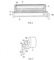
- FIG. 2 is a side view of the configuration of the secondary transfer roller unit 7 as viewed from the upstream side thereof.
- FIG. 3 is an outline perspective view of a drive transmission mechanism for pivot operation of the eccentric cam 76.
- the secondary transfer roller 71 holds, together with the secondary transfer backup roller 64, the intermediate transfer belt 61 and the medium M to thereby form the secondary transferring section.
- the secondary transfer roller 71 rotates along with traveling of the intermediate transfer belt 61 and the medium M, and causes positional difference between the secondary transfer roller 71 and the secondary transfer backup roller 64, thereby performing, to the medium M, the secondary transfer of the toner images that have been transferred by means of the primary transfer to the transferred surface 61S.
- the support 72 rotatably supports both ends of the secondary transfer roller 71.
- the support 72 corresponds to a specific but non-limiting example of a "support” in one embodiment of the invention.
- the support 72 may be fixed to the rod-shaped shaft member 73 that extends in the lateral direction along the secondary transfer roller 71, and pivot within a range illustrated by an arrow Y72 ( FIG. 1 ) with the shaft member 73 as a supporting point.
- the shaft member 74 penetrates through the support 72 in the lateral direction, and may be fixed to the support 72 to allow both ends thereof to protrude from the support 72.
- a peripheral surface of the shaft member 74 comes into contact with a peripheral surface 76S of the eccentric cam 76, and slides on the peripheral surface 76S of the eccentric cam 76 along with the pivot of the eccentric cam 76.
- Two eccentric cams 76 may be preferably provided such that respective eccentric cams 76 come into contact with both ends of the shaft member 74 ( FIG. 2 ).
- the eccentric cam 76 may be fixed to the shaft member 75, and may be pivotable within a range illustrated by an arrow Y76 ( FIG. 1 ) around the shaft member 75.
- the shaft member 74 slides on the peripheral surface 76S of the eccentric cam 76 along with such pivot of the eccentric cam 76, which changes attitude of the support 72.
- a part that is located relatively far from the shaft member 75, of the peripheral surface 76S of the eccentric cam 76 may come into contact with the shaft member 74, and the support 72 may accordingly be pushed up to a relatively high position.
- This state corresponds to a specific but non-limiting example of a "biasing state" in one embodiment of the invention, in which the secondary transfer roller 71 supported by the support 72 biases the intermediate transfer belt 61 toward the secondary transfer backup roller 64.
- the eccentric cam 76 may be moved to a position that is rotated rightward by, for example, 90 degrees from the position of FIG. 1 .
- a part that is located relatively close to the shaft member 75, of the peripheral surface 76S of the eccentric cam 76 may come into contact with the shaft member 74, and the support 72 may accordingly be dropped down to a low position relatively.
- This state corresponds to a specific but non-limiting example of a "separated state" in one embodiment of the invention, in which the secondary transfer roller 71 supported by the support 72 is separated away from the intermediate transfer belt 61. Note that, in this example, the support 72 falls freely by own weight due to change in the pivot position of the eccentric cam 76 that is supported by the support 72.
- a biasing member such as a spring may be used to actively push the support 72 downward.
- a change in attitude change of the support 72 allows the secondary transfer roller 71 supported by the support 72 to perform the approaching operation in which the secondary transfer roller 71 approaches toward the intermediate transfer belt 61 and the separating operation in which the secondary transfer roller 71 is separated away from the intermediate transfer belt 61.
- the secondary transfer roller 71 may be operable to make a transition between the biasing state and the separated state.
- the separating operation that causes the secondary transfer roller 71 to be separated away from the intermediate transfer belt 61 may be carried out, for example, in the case where malfunction occurs in traveling of the medium M, in the case where a correction operation such as print density correction and color deviation correction is performed, upon standby in which the printing operation is not performed, or in any other occasion.
- the secondary transfer roller unit 7 further includes a motor 77 serving as a driving source that generates driving force, and gears 78A to 78E that transmit the driving force to the shaft member 75.
- the motor 77 corresponds to a specific but non-limiting example of a "driver" in one embodiment of the invention.
- the motor 77 may be provided with a shaft 77J, and the driving force may be transmitted to the gear 78A through rotation of the shaft 77J.
- the gear 78A engages with the gear 78B, the gear 78B engages with the gear 78C, the gear 78C engages with the gear 78D, the gear 78D engages with the gear 78E, and the gear 78E may be fixed to an end of the shaft member 75.
- the gears 78A to 78E and the shaft member 75 rotate in conjunction with one another, and the eccentric cam 76 accordingly pivots around the shaft member 75.
- the pivoting of the eccentric cam 76 by means of the driving force of the motor 77 causes the eccentric cam 76 itself to bias the support 72 and bring the secondary transfer roller 71 close to the intermediate transfer belt 61.
- adjusting a rotation amount of the motor 77 makes it possible to appropriately change the pivot position of the eccentric cam 76, namely, attitude of the support 72.
- the support 72 further includes a retaining member 79 at an upper part thereof.
- the retaining member 79 corresponds to a specific but non-limiting example of a "biasing member” in one embodiment of the invention.
- a combination of the retaining member 79 and the motor 77 corresponds to a specific but non-limiting example of a "separator” in one embodiment of the invention.
- the retaining member 79 forms an opening 72K together with the support 72. Upon the printing operation illustrated in FIG. 1 , the retaining member 79 may be located between the second roller pair 22 and the secondary transferring section, and the medium M traveling toward the secondary transferring section passes through the opening 72K.
- the retaining member 79 be prevented from coming into contact with the medium M (be separated away from the medium M).
- the retaining member 79 may be in contact with an upper surface MS of the medium M at the upstream side of the secondary transferring section, and push down the medium M.
- the retaining member 79 that is fixed to the support 72 biases the medium M in a direction away from the intermediate transfer belt 61.
- a separating operation in which the medium M is separated and the separating operation of the secondary transfer roller 71 may be carried out in conjunction with each other by means of the movement of the retaining member 79 and the support 72, namely, by means of the change in attitude of the suppor 72 thereby causing both the secondary transfer roller 71 and the medium M to be separated away from the intermediate transfer belt 61.
- the secondary transfer roller 71 in the biasing state, the secondary transfer roller 71 is in contact with the intermediate transfer belt 61 with the medium M in between whereas the retaining member 79 is separated away from the medium M.
- the secondary transfer roller 71 may be separated away from the intermediate transfer belt 61 at timing different from timing at which the medium M may be separated away from the intermediate transfer belt 61.
- the holding state of the medium M by the secondary transfer roller 71 and the intermediate transfer belt 61 may be released but the biasing operation of the retaining member 79 with respect to the medium M has not been started. This is due to a gap provided between the retaining member 79 and the medium M, and a predetermined time is thus necessary for the retaining member 79 to come close to and come into contact with the medium M.
- the retaining member 79 starts to separate the medium M away from the intermediate transfer belt 61 after the secondary transfer roller 71 starts making a transition from the biasing state to the separated state.
- the toner images may be transferred to the medium M in the following manner.
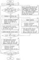
- An operation of the image forming apparatus according to the first embodiment is described below with reference to FIG. 5.
- FIG. 5 is a flowchart for describing the operation of the image forming apparatus according to the first embodiment.
- FIG. 6 is a diagram illustrating, upon standby before the medium M is inserted, an overall configuration example of the image forming apparatus according to the first embodiment.
- step S2 a determination is made as to whether to perform density correction and color deviation correction of the toner images.
- step S3 the density correction and the color deviation correction of the toner images are performed (step S3).
- the controller 11 activates the developing devices 51A to 51E and the intermediate transfer belt 61, and a correction toner image may be formed on the transferred surface 61S of the intermediate transfer belt 61. Further, the sensor group 8 detects the correction toner image, and the controller 11 performs the density correction and the color deviation correction of the toner images, on the basis of the detected data.
- printing job may be transmitted from an external apparatus or any other apparatus to the controller 11 (step S4).
- the controller 11 When receiving the printing job, the controller 11 activates the motor 77, and allows the eccentric cam 76 to pivot to thereby push up the support 72, causing the secondary transfer roller 71 to nip the intermediate transfer belt 61. Further, the controller 11 brings the roller 41 and the roller 42 close to each other, thereby causing them to nip each other (step S5).
- the controller 11 activates the developing devices 51A to 51E, the intermediate transfer belt 61, and the fixing section 4 (step S6).
- the toner image may be formed on (transferred by means of the primary transfer to) the transferred surface 61S of the intermediate transfer belt 61 through the electrophotography process.
- the medium M may be fed out from the roll MR, and the medium conveying section 2 may be activated to feed the medium M to the secondary transferring section.
- the toner image on the transferred surface 61S may be transferred (transferred by means of the secondary transfer) to the medium M, and the toner image may be then fixed to the medium M by the fixing section 4 (step S7).
- step S8 a determination is made as to whether a situation in which the medium M is not properly conveyed, namely, so-called paper jam has occurred in the printing operation.
- the controller 11 stops the developing devices 51A to 51E, the intermediate transfer belt 61, and the fixing section 4 (step S12). Further, the controller 11 activates the motor 77, and causes the eccentric cam 76 to pivot to thereby move the support 72 downward, separating the secondary transfer roller 71 and the medium M from the intermediate transfer belt 61 and separating the roller 41 and the roller 42 from each other (step S13). Thereafter, the process returns to step S5 after the jammed medium M is removed (step S14).
- step S8 when it is determined that paper jam has not occurred in the printing operation (NO in step S8), the controller 11 stops the developing devices 51A to 51E, the intermediate transfer belt 61, the fixing section 4, and the medium conveying section 2 (step S9). Then, the controller 11 separates the roller 41 and the roller 42 away from each other. Further, the controller 11 activates the motor 77, and causes the eccentric cam 76 to pivot to thereby move the support 72 downward, separating the secondary transfer roller 71 and the medium M from the intermediate transfer belt 61 (step S10). Thereafter, when the printing operation is to be further performed repeatedly (YES in step S11), the process returns to step S2.
- the correction operation may be performed again (step S3).
- the correction operation is free from any influence caused by the remaining of the medium M in the image forming section 3, owing to the separation of the medium M away from the intermediate transfer belt 61 by the retaining member 79.
- step S10 When the printing operation is not to be performed any more in step S10 (NO in step S11), the main power supply may be turned off and the series of operations may be completed (end).
- the medium M is separated away from the intermediate transfer belt 61 by the retaining member 79 that is driven by the motor 77, during the operation stop (in standby).
- a correction operation for formation of the developer image on the intermediate transfer belt 61 such as print density correction and the color deviation correction
- Japanese Unexamined Patent Application Publication No. 2015-25920 mentioned above involves a risk in which the medium may come into contact with the image holding body B.
- the present embodiment allows the intermediate transfer belt 61 and the medium M to be separated away from each other with higher possibility, preventing the medium M from being stained by the correction operation.
- the retaining member 79 comes into contact with the upper surface MS of the medium M at the upstream of the secondary transferring section, and pushes down the medium M, it is possible to prevent the toner from being attached to the retaining member 79. If the retaining member 79 is located downstream of the secondary transferring section, the toner of the intermediate transfer belt 61 may possibly be attached to the retaining member 79.
- the roller pair 22, the secondary transferring section, and the fixing section 4 may be arranged in a straight line (so-called straight path is formed). This makes it possible to handle various print media such as special paper.
- the driving force derived from the single motor 77 may be used to perform the separating operation that causes the secondary transfer roller 71 to be separated away from the intermediate transfer belt 61 and the separating operation that causes the medium M to be separated away from the intermediate transfer belt 61 in conjunction with each other. This achieves a simplified control operation and a simplified configuration.
- the support 72 that supports the secondary transfer roller 71 may be integrated with the retaining member 79 that retains the medium M, which achieves a simplifier configuration.
- the biasing operation performed on the medium M by the retaining member 79 may be carried out after the holding state of the medium M by the secondary transferring section is released. This makes it possible to reduce a load applied to, for example, the intermediate transfer belt 61 and the medium M. As a result, for example, it is possible to avoid a decrease in quality of printed image.
- the image forming apparatus therefore makes it possible to form an image with better quality.
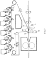
- FIG. 7 is a schematic diagram illustrating an overall configuration example of an image forming apparatus according to a modification of the first embodiment of the invention.
- the present modification has a configuration same as that of the image forming apparatus according to the above-described first embodiment, except that the retaining member 79 is provided downstream of the secondary transferring section in which the secondary transfer backup roller 64 and the secondary transfer roller 71 face each other.
- the configuration according to the present modification may be employed in a case where it is difficult to dispose the retaining member 79 between the roller pair 22 and the secondary transferring section due to restrictions on the configuration.
- the configuration may be employed when a distance between the roller pair 22 and the secondary transferring section is narrow.
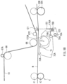
- FIG. 8A is a schematic diagram illustrating, upon the printing operation, a configuration example of a key part of an image forming apparatus according to a second embodiment of the invention.
- FIG. 8B is a schematic diagram illustrating, upon standby, a configuration example of the key part of the image forming apparatus according to the second embodiment of the invention.
- the image forming apparatus has a configuration substantially similar to that of the image forming apparatus according to the first embodiment, except that a secondary transfer roller unit 7A is provided in place of the secondary transfer roller unit 7, and a retaining member 12 that retains the medium M is provided separately from the secondary transfer roller unit 7A.
- the intermediate transfer unit 6 of the image forming apparatus further includes a support roller 67C that is provided near the upstream side of the secondary transfer backup roller 64.
- the support roller 67C stretches the intermediate transfer belt 61.
- Providing the support roller 67C makes it possible to bring the intermediate transfer belt 61 between the secondary transfer backup roller 64 and the support roller 67C, closer to the medium M that is conveyed through the roller pair 22 and the secondary transferring section. More specifically, providing the support roller 67C allows the intermediate transfer belt 61 to so travel as to be substantially parallel even more to the medium M that is about to go into the secondary transferring section. Hence, it is possible to expect an improvement in print quality of the toner image that is transferred to the medium M.
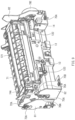
- FIG. 9 is a perspective view of the secondary transfer roller unit 7A and the retaining member 12.
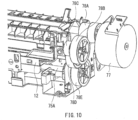
- FIG. 10 is a perspective view of a part of the secondary transfer roller unit 7A and the retaining member 12.
- FIG. 11 is an exploded perspective view of a part of the secondary transfer roller unit 7A.
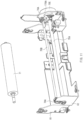
- FIG. 12 is a perspective view of the retaining member 12.
- the secondary transfer roller unit 7A has a configuration substantially similar to that of the secondary transfer roller unit 7 according to the above-described first embodiment, except that the secondary transfer roller unit 7A includes a support 72A that rotatably supports the secondary transfer roller 71, shaft members 73A to 75A and 75B, and an eccentric cam 76A.
- the driving force of the motor 77 may be transmitted to the shaft member 75A through the gears 78A to 78E (see FIG. 10 or any other drawing).
- two eccentric cams 76A may be so provided as to sandwich the support 72A in the lateral direction.
- the two eccentric cams 76A may be coupled to each other through the two shaft members 75A and 75B that extend in the lateral direction.
- the support 72 may be so held by a frame 81 that is fixed to the image forming apparatus main body, as to be pivotable with the shaft member 73A as a supporting point.
- Each of the eccentric cams 76A may be so held by a frame 82 that is fixed to the image forming apparatus main body, as to be pivotable around the shaft member 75A.
- FIG. 8A illustrates the biasing state in which the secondary transfer roller 71 biases the intermediate transfer belt 61 toward the secondary transfer backup roller 64
- FIG. 8B illustrates the separated state in which the secondary transfer roller 71 is separated away from the intermediate transfer belt 61.
- the retaining member 12 includes a retaining part 121, a supporting part 122, and a cam receiving part 123 (for example, see FIG. 12 ).
- the retaining part 121 extends in the lateral direction, and comes into contact with the medium M upon the separating operation of the medium M.
- the retaining part 121 may have a substantially V-shaped cross section orthogonal to the lateral direction, for example ( FIG. 1 ).
- the supporting part 122 supports the retaining part 121 from below, and forms an opening 12K through which the medium M passes, together with the retaining part 121.
- the cam receiving part 123 may be a protrusion that is installed upright on the supporting part 122 and extends in the lateral direction.
- the cam receiving part 123 comes into contact with the shaft member 75B that is fixed to the eccentric cam 76A, to receive downward biasing force, when the medium M is to be separated away from the intermediate transfer belt 61.
- the cam receiving part 123 may be separated away from the shaft member 75B.
- the retaining member 12 may be held by, for example, the frame 82 to be movable in the vertical direction.
- a biasing member 13 such as a plate spring and a coil spring may be provided below the supporting part 122.
- the retaining member 12 may be biased upward by biasing force of the biasing member 13. Therefore, upon the printing operation illustrated in FIG. 8A , the cam receiving part 123 does not receive the biasing force from the shaft member 75B.
- the retaining part 121 accordingly receives only the biasing force of the biasing member 13 through the cam receiving part 123 and the supporting part 122, thereby maintaining the separated state from the medium M. Therefore, in the biasing state, the secondary transfer roller 71 may be separated away from the intermediate transfer belt 61 at timing different from timing at which the medium M may be separated away from the intermediate transfer belt 61. In detail, at the time immediately after the support 72A starts to change its attitude (to move from the state in FIG. 8A to the state in FIG. 8B ), the holding state of the medium M by the secondary transfer roller 71 and the intermediate transfer belt 61 may be released but the biasing operation of the retaining part 121 with respect to the medium M has not been started.
- the medium M may be held, together with the intermediate transfer belt 61, between the secondary transfer backup roller 64 and the secondary transfer roller 71 in the secondary transferring section, and the retaining member 12 may be retracted to a position separated from the medium M ( FIG. 8A ), as with the image forming apparatus according to the foregoing first embodiment.
- the eccentric cam 76A pivots leftward within a range of an arrow 76A. Further, the part that is located relatively far from the shaft member 75A, of the peripheral surface 76AS of the eccentric cam 76A may come into contact with the shaft member 74A, and the support 72A may be pushed up to a high position relatively.
- the medium M may be retracted to a position separated from the intermediate transfer belt 61 by the retaining member 12, and the secondary transfer roller 71 may also be retracted to a position separated from the intermediate transfer belt 61. At this time, the medium M may be separated also from the secondary transfer roller 71. More specifically, as illustrated by way of example in FIG. 8B , the eccentric cam 76A may make a transition to a position that is rotated rightward within the range (for example, 90 degrees) of the arrow Y76A from the position in FIG. 8A .
- the series of operations described above may be controlled by the controller 11, as with the above-described first embodiment.
- the pivot position of the eccentric cam 76A may be detected by a position sensor 14 ( FIG. 9 ) such as an optical sensor.
- the foregoing second embodiment also makes it possible to achieve effects similar to those of the above-described first embodiment. Since the support 72A that supports the secondary transfer roller 71 and the retaining member 12 that retains the medium M are provided separately from each other, flexibility in design relating to arrangement of the support 72A and the retaining member 12 is increased as compared with the first embodiment in which the support and the retaining member are integrated. Further, the retaining member 12 may be forcibly brought into contact with the medium M by the eccentric cam 76A by means of the driving force derived from the motor 77. Therefore, it is possible to ensure that the medium M is separated away from the intermediate transfer belt 61 even when the medium M is large in thickness or high in hardness.
- the support 72A and the retaining member 12 separately from each other makes it possible to individually set the retracted positions upon the standby of the secondary transfer roller 71 and the medium M. This makes it possible to ensure that the contact between the secondary transfer roller 71 and the medium M is prevented. Further, a load applied to the secondary transfer roller 71 is reduced, and allowing for expectation for longer life of the secondary transfer roller 71.
- the intermediate transfer belt 61 is separated away from the medium M during the operation stop (upon the standby), allowing for detachment of the intermediate transfer unit 6. This facilitates a replacement operation of the intermediate transfer unit 6 attributable to the deterioration of the intermediate transfer belt 61 or any other component.
- the biasing operation performed on the medium M by the retaining part 121 may be carried out after the holding state of the medium M by the secondary transferring section is released. This makes it possible to reduce a load applied to, for example, the intermediate transfer belt 61 and the medium M. As a result, for example, it is possible to avoid a decrease in quality of printed image.
- FIG. 13A and FIG. 13B each schematically illustrate a configuration example of a key part of an image forming apparatus according to a modification of the second embodiment of the invention.
- the present modification has a configuration same as that of the image forming apparatus according to the above-described second embodiment, except that a retaining member 15 fixed to the intermediate transfer unit 6 is provided in place of the retaining member 12.
- the retaining member 15 may be so fixed to a main body of the intermediate transfer unit 6 as to be rotatable around a shaft 15J.
- the retaining member 15 has a retaining part 15A at a front end thereof.
- the retaining part 15A may be retracted to a position separated from the medium M upon the printing operation ( FIG. 13A ), and the retaining part 15A biases the medium M downward (in a direction in which the medium M is separated away from the intermediate transfer belt 61) upon the standby ( FIG. 13B ).
- a coil spring 16 serving as a biasing member may be provided at a location that is in the vicinity of an end, of the retaining member 15, on the opposite side of the retaining part 15A.
- the retaining member 15 may be pulled by biasing force of the coil spring 16 in a direction of an arrow Y16B, which causes the retaining part 15A to bias the medium M downward.
- driving force derived from the motor or any other component may be transmitted to the retaining member 15 through the shaft 15J, which causes the retaining member 15 to rotate around the shaft 15J in a direction of an arrow Y16B that is a direction against the biasing force of the coil spring 16 (in a direction in which the coil spring 16 is extended).
- the retaining part 15A is retracted to a position separated from the medium M.
- the configuration according to the present modification may be employed in a case where there are restrictions on the configuration.
- the configuration may be employed when sufficient space is not secured around the secondary transfer roller unit 7A.
- the image forming apparatus may transfer only a toner image of a black color to thereby form a monochrome image.
- the support 72 is moved downward by own weight in the above-described first embodiment.
- the support 72 may be forcibly moved downward by a biasing member such as a coil spring.
- the support 72 may be forcibly moved upward by a biasing member such as a coil spring, and the support 72 may be forcibly moved downward by the eccentric cam 76.
- the image forming apparatus is not limited thereto. Any embodiment of the invention is applicable to an image forming unit that functions as a multifunctional peripheral having a function such as a scanner function, a facsimile function, and an image displaying function, in addition to the printing function.
Landscapes
- Physics & Mathematics (AREA)
- General Physics & Mathematics (AREA)
- Engineering & Computer Science (AREA)
- Microelectronics & Electronic Packaging (AREA)
- Electrostatic Charge, Transfer And Separation In Electrography (AREA)
- Control Or Security For Electrophotography (AREA)
Applications Claiming Priority (1)
| Application Number | Priority Date | Filing Date | Title |
|---|---|---|---|
| JP2015178631A JP6465779B2 (ja) | 2015-09-10 | 2015-09-10 | 画像形成装置 |
Publications (2)
| Publication Number | Publication Date |
|---|---|
| EP3144736A1 EP3144736A1 (en) | 2017-03-22 |
| EP3144736B1 true EP3144736B1 (en) | 2023-05-10 |
Family
ID=56683770
Family Applications (1)
| Application Number | Title | Priority Date | Filing Date |
|---|---|---|---|
| EP16183509.5A Active EP3144736B1 (en) | 2015-09-10 | 2016-08-10 | Image forming apparatus |
Country Status (3)
| Country | Link |
|---|---|
| US (1) | US9835988B2 (enExample) |
| EP (1) | EP3144736B1 (enExample) |
| JP (1) | JP6465779B2 (enExample) |
Families Citing this family (5)
| Publication number | Priority date | Publication date | Assignee | Title |
|---|---|---|---|---|
| JP6123940B1 (ja) * | 2016-09-28 | 2017-05-10 | 富士ゼロックス株式会社 | 画像形成装置 |
| JP7003426B2 (ja) * | 2017-03-23 | 2022-01-20 | 富士フイルムビジネスイノベーション株式会社 | 画像形成装置 |
| JP7009847B2 (ja) * | 2017-09-05 | 2022-01-26 | コニカミノルタ株式会社 | 画像形成装置、用紙処理システム及びプログラム |
| JP7030465B2 (ja) * | 2017-09-27 | 2022-03-07 | キヤノン株式会社 | 転写ユニットおよび画像形成装置 |
| US20220043388A1 (en) * | 2019-04-30 | 2022-02-10 | Hewlett-Packard Development Company, L.P. | Toner hopper heating device |
Citations (4)
| Publication number | Priority date | Publication date | Assignee | Title |
|---|---|---|---|---|
| JP2004021237A (ja) * | 2002-06-20 | 2004-01-22 | Toray Eng Co Ltd | 電子写真プリンタ |
| JP2010097132A (ja) * | 2008-10-20 | 2010-04-30 | Casio Electronics Co Ltd | 連続紙印刷装置 |
| JP2014122960A (ja) * | 2012-12-20 | 2014-07-03 | Casio Electronics Co Ltd | 印刷装置 |
| JP2015025920A (ja) * | 2013-07-25 | 2015-02-05 | 富士ゼロックス株式会社 | 画像形成装置 |
Family Cites Families (10)
| Publication number | Priority date | Publication date | Assignee | Title |
|---|---|---|---|---|
| JPS5034543A (enExample) * | 1973-07-27 | 1975-04-02 | ||
| JPS63315451A (ja) * | 1987-01-17 | 1988-12-23 | Asahi Optical Co Ltd | 電子写真用被記録媒体供給方法 |
| JP2556261Y2 (ja) * | 1990-11-30 | 1997-12-03 | 株式会社サトー | 電子写真装置における転写部の紙押え機構 |
| JP2000181320A (ja) | 1998-12-11 | 2000-06-30 | Hitachi Koki Co Ltd | 両面記録用の電子写真装置 |
| JP2003076153A (ja) * | 2001-08-31 | 2003-03-14 | Minolta Co Ltd | 画像形成装置 |
| JP2004252258A (ja) * | 2003-02-21 | 2004-09-09 | Canon Inc | 画像形成装置 |
| JP5353041B2 (ja) * | 2008-03-26 | 2013-11-27 | 株式会社リコー | 加圧機構、転写装置、及び、画像形成装置 |
| JP5888587B2 (ja) * | 2011-03-07 | 2016-03-22 | 株式会社リコー | 画像形成装置 |
| US8538306B2 (en) * | 2011-05-23 | 2013-09-17 | Xerox Corporation | Web feed system having compensation roll |
| US20120308274A1 (en) * | 2011-06-03 | 2012-12-06 | Xerox Corporation | Single btr roll at stripper for continuous web transfer |
-
2015
- 2015-09-10 JP JP2015178631A patent/JP6465779B2/ja active Active
-
2016
- 2016-08-10 EP EP16183509.5A patent/EP3144736B1/en active Active
- 2016-08-12 US US15/235,246 patent/US9835988B2/en active Active
Patent Citations (4)
| Publication number | Priority date | Publication date | Assignee | Title |
|---|---|---|---|---|
| JP2004021237A (ja) * | 2002-06-20 | 2004-01-22 | Toray Eng Co Ltd | 電子写真プリンタ |
| JP2010097132A (ja) * | 2008-10-20 | 2010-04-30 | Casio Electronics Co Ltd | 連続紙印刷装置 |
| JP2014122960A (ja) * | 2012-12-20 | 2014-07-03 | Casio Electronics Co Ltd | 印刷装置 |
| JP2015025920A (ja) * | 2013-07-25 | 2015-02-05 | 富士ゼロックス株式会社 | 画像形成装置 |
Also Published As
| Publication number | Publication date |
|---|---|
| JP6465779B2 (ja) | 2019-02-06 |
| US20170075262A1 (en) | 2017-03-16 |
| JP2017054035A (ja) | 2017-03-16 |
| US9835988B2 (en) | 2017-12-05 |
| EP3144736A1 (en) | 2017-03-22 |
Similar Documents
| Publication | Publication Date | Title |
|---|---|---|
| JP5349999B2 (ja) | プロセスカートリッジおよび画像形成装置 | |
| US8244168B2 (en) | Image forming apparatus with movable transfer device | |
| JP5060315B2 (ja) | 定着装置及びこれを備えた画像形成装置 | |
| EP3144736B1 (en) | Image forming apparatus | |
| CN113820935B (zh) | 成像装置 | |
| JP5561612B2 (ja) | 画像形成装置 | |
| JP5339750B2 (ja) | 画像形成装置 | |
| JP2019045580A (ja) | 画像形成装置 | |
| JP5910919B2 (ja) | 画像形成装置 | |
| WO2020171215A1 (ja) | 画像形成装置 | |
| JP2011002622A (ja) | カラー電子写真画像形成装置 | |
| US11592758B2 (en) | Photosensitive member unit capable of preventing a photosensitive member and a charging roller from accidentally being released from a separation state | |
| US9639030B2 (en) | Image forming apparatus for applying a lubricant to an image-bearing member | |
| CN114236997B (zh) | 单色成像装置 | |
| JP2009003304A (ja) | 画像形成装置 | |
| JP7139671B2 (ja) | 定着装置、画像形成装置および圧接状態切換装置 | |
| JP2005316320A (ja) | 画像形成装置 | |
| JP5354374B2 (ja) | 画像形成装置 | |
| US11835914B2 (en) | Apparatus having a replaceable cover | |
| JP2011248320A (ja) | 画像形成装置 | |
| JP2010271504A (ja) | 定着装置及びこれを備えた画像形成装置 | |
| EP2413199B1 (en) | Fixing device and image forming apparatus incorporating same | |
| JP5306271B2 (ja) | 軸部材保持機構、感光体ドラムユニット及び画像形成装置 | |
| JP7767059B2 (ja) | 画像形成装置 | |
| JP2020020974A (ja) | 画像形成装置 |
Legal Events
| Date | Code | Title | Description |
|---|---|---|---|
| PUAI | Public reference made under article 153(3) epc to a published international application that has entered the european phase |
Free format text: ORIGINAL CODE: 0009012 |
|
| STAA | Information on the status of an ep patent application or granted ep patent |
Free format text: STATUS: THE APPLICATION HAS BEEN PUBLISHED |
|
| AK | Designated contracting states |
Kind code of ref document: A1 Designated state(s): AL AT BE BG CH CY CZ DE DK EE ES FI FR GB GR HR HU IE IS IT LI LT LU LV MC MK MT NL NO PL PT RO RS SE SI SK SM TR |
|
| AX | Request for extension of the european patent |
Extension state: BA ME |
|
| STAA | Information on the status of an ep patent application or granted ep patent |
Free format text: STATUS: REQUEST FOR EXAMINATION WAS MADE |
|
| 17P | Request for examination filed |
Effective date: 20170922 |
|
| RBV | Designated contracting states (corrected) |
Designated state(s): AL AT BE BG CH CY CZ DE DK EE ES FI FR GB GR HR HU IE IS IT LI LT LU LV MC MK MT NL NO PL PT RO RS SE SI SK SM TR |
|
| STAA | Information on the status of an ep patent application or granted ep patent |
Free format text: STATUS: EXAMINATION IS IN PROGRESS |
|
| 17Q | First examination report despatched |
Effective date: 20210426 |
|
| RAP1 | Party data changed (applicant data changed or rights of an application transferred) |
Owner name: OKI ELECTRIC INDUSTRY CO., LTD. |
|
| GRAP | Despatch of communication of intention to grant a patent |
Free format text: ORIGINAL CODE: EPIDOSNIGR1 |
|
| STAA | Information on the status of an ep patent application or granted ep patent |
Free format text: STATUS: GRANT OF PATENT IS INTENDED |
|
| INTG | Intention to grant announced |
Effective date: 20230216 |
|
| GRAS | Grant fee paid |
Free format text: ORIGINAL CODE: EPIDOSNIGR3 |
|
| GRAA | (expected) grant |
Free format text: ORIGINAL CODE: 0009210 |
|
| STAA | Information on the status of an ep patent application or granted ep patent |
Free format text: STATUS: THE PATENT HAS BEEN GRANTED |
|
| AK | Designated contracting states |
Kind code of ref document: B1 Designated state(s): AL AT BE BG CH CY CZ DE DK EE ES FI FR GB GR HR HU IE IS IT LI LT LU LV MC MK MT NL NO PL PT RO RS SE SI SK SM TR |
|
| REG | Reference to a national code |
Ref country code: GB Ref legal event code: FG4D |
|
| REG | Reference to a national code |
Ref country code: AT Ref legal event code: REF Ref document number: 1567290 Country of ref document: AT Kind code of ref document: T Effective date: 20230515 Ref country code: CH Ref legal event code: EP |
|
| REG | Reference to a national code |
Ref country code: DE Ref legal event code: R096 Ref document number: 602016079289 Country of ref document: DE |
|
| REG | Reference to a national code |
Ref country code: IE Ref legal event code: FG4D |
|
| REG | Reference to a national code |
Ref country code: NL Ref legal event code: FP |
|
| REG | Reference to a national code |
Ref country code: LT Ref legal event code: MG9D |
|
| REG | Reference to a national code |
Ref country code: AT Ref legal event code: MK05 Ref document number: 1567290 Country of ref document: AT Kind code of ref document: T Effective date: 20230510 |
|
| PG25 | Lapsed in a contracting state [announced via postgrant information from national office to epo] |
Ref country code: SE Free format text: LAPSE BECAUSE OF FAILURE TO SUBMIT A TRANSLATION OF THE DESCRIPTION OR TO PAY THE FEE WITHIN THE PRESCRIBED TIME-LIMIT Effective date: 20230510 Ref country code: PT Free format text: LAPSE BECAUSE OF FAILURE TO SUBMIT A TRANSLATION OF THE DESCRIPTION OR TO PAY THE FEE WITHIN THE PRESCRIBED TIME-LIMIT Effective date: 20230911 Ref country code: NO Free format text: LAPSE BECAUSE OF FAILURE TO SUBMIT A TRANSLATION OF THE DESCRIPTION OR TO PAY THE FEE WITHIN THE PRESCRIBED TIME-LIMIT Effective date: 20230810 Ref country code: ES Free format text: LAPSE BECAUSE OF FAILURE TO SUBMIT A TRANSLATION OF THE DESCRIPTION OR TO PAY THE FEE WITHIN THE PRESCRIBED TIME-LIMIT Effective date: 20230510 Ref country code: AT Free format text: LAPSE BECAUSE OF FAILURE TO SUBMIT A TRANSLATION OF THE DESCRIPTION OR TO PAY THE FEE WITHIN THE PRESCRIBED TIME-LIMIT Effective date: 20230510 |
|
| PG25 | Lapsed in a contracting state [announced via postgrant information from national office to epo] |
Ref country code: RS Free format text: LAPSE BECAUSE OF FAILURE TO SUBMIT A TRANSLATION OF THE DESCRIPTION OR TO PAY THE FEE WITHIN THE PRESCRIBED TIME-LIMIT Effective date: 20230510 Ref country code: PL Free format text: LAPSE BECAUSE OF FAILURE TO SUBMIT A TRANSLATION OF THE DESCRIPTION OR TO PAY THE FEE WITHIN THE PRESCRIBED TIME-LIMIT Effective date: 20230510 Ref country code: LV Free format text: LAPSE BECAUSE OF FAILURE TO SUBMIT A TRANSLATION OF THE DESCRIPTION OR TO PAY THE FEE WITHIN THE PRESCRIBED TIME-LIMIT Effective date: 20230510 Ref country code: LT Free format text: LAPSE BECAUSE OF FAILURE TO SUBMIT A TRANSLATION OF THE DESCRIPTION OR TO PAY THE FEE WITHIN THE PRESCRIBED TIME-LIMIT Effective date: 20230510 Ref country code: IS Free format text: LAPSE BECAUSE OF FAILURE TO SUBMIT A TRANSLATION OF THE DESCRIPTION OR TO PAY THE FEE WITHIN THE PRESCRIBED TIME-LIMIT Effective date: 20230910 Ref country code: HR Free format text: LAPSE BECAUSE OF FAILURE TO SUBMIT A TRANSLATION OF THE DESCRIPTION OR TO PAY THE FEE WITHIN THE PRESCRIBED TIME-LIMIT Effective date: 20230510 Ref country code: GR Free format text: LAPSE BECAUSE OF FAILURE TO SUBMIT A TRANSLATION OF THE DESCRIPTION OR TO PAY THE FEE WITHIN THE PRESCRIBED TIME-LIMIT Effective date: 20230811 |
|
| PG25 | Lapsed in a contracting state [announced via postgrant information from national office to epo] |
Ref country code: FI Free format text: LAPSE BECAUSE OF FAILURE TO SUBMIT A TRANSLATION OF THE DESCRIPTION OR TO PAY THE FEE WITHIN THE PRESCRIBED TIME-LIMIT Effective date: 20230510 |
|
| PG25 | Lapsed in a contracting state [announced via postgrant information from national office to epo] |
Ref country code: SK Free format text: LAPSE BECAUSE OF FAILURE TO SUBMIT A TRANSLATION OF THE DESCRIPTION OR TO PAY THE FEE WITHIN THE PRESCRIBED TIME-LIMIT Effective date: 20230510 |
|
| PG25 | Lapsed in a contracting state [announced via postgrant information from national office to epo] |
Ref country code: SM Free format text: LAPSE BECAUSE OF FAILURE TO SUBMIT A TRANSLATION OF THE DESCRIPTION OR TO PAY THE FEE WITHIN THE PRESCRIBED TIME-LIMIT Effective date: 20230510 Ref country code: SK Free format text: LAPSE BECAUSE OF FAILURE TO SUBMIT A TRANSLATION OF THE DESCRIPTION OR TO PAY THE FEE WITHIN THE PRESCRIBED TIME-LIMIT Effective date: 20230510 Ref country code: RO Free format text: LAPSE BECAUSE OF FAILURE TO SUBMIT A TRANSLATION OF THE DESCRIPTION OR TO PAY THE FEE WITHIN THE PRESCRIBED TIME-LIMIT Effective date: 20230510 Ref country code: EE Free format text: LAPSE BECAUSE OF FAILURE TO SUBMIT A TRANSLATION OF THE DESCRIPTION OR TO PAY THE FEE WITHIN THE PRESCRIBED TIME-LIMIT Effective date: 20230510 Ref country code: DK Free format text: LAPSE BECAUSE OF FAILURE TO SUBMIT A TRANSLATION OF THE DESCRIPTION OR TO PAY THE FEE WITHIN THE PRESCRIBED TIME-LIMIT Effective date: 20230510 Ref country code: CZ Free format text: LAPSE BECAUSE OF FAILURE TO SUBMIT A TRANSLATION OF THE DESCRIPTION OR TO PAY THE FEE WITHIN THE PRESCRIBED TIME-LIMIT Effective date: 20230510 |
|
| REG | Reference to a national code |
Ref country code: DE Ref legal event code: R097 Ref document number: 602016079289 Country of ref document: DE |
|
| PG25 | Lapsed in a contracting state [announced via postgrant information from national office to epo] |
Ref country code: MC Free format text: LAPSE BECAUSE OF FAILURE TO SUBMIT A TRANSLATION OF THE DESCRIPTION OR TO PAY THE FEE WITHIN THE PRESCRIBED TIME-LIMIT Effective date: 20230510 |
|
| PLBE | No opposition filed within time limit |
Free format text: ORIGINAL CODE: 0009261 |
|
| STAA | Information on the status of an ep patent application or granted ep patent |
Free format text: STATUS: NO OPPOSITION FILED WITHIN TIME LIMIT |
|
| REG | Reference to a national code |
Ref country code: CH Ref legal event code: PL |
|
| PG25 | Lapsed in a contracting state [announced via postgrant information from national office to epo] |
Ref country code: MC Free format text: LAPSE BECAUSE OF FAILURE TO SUBMIT A TRANSLATION OF THE DESCRIPTION OR TO PAY THE FEE WITHIN THE PRESCRIBED TIME-LIMIT Effective date: 20230510 |
|
| PG25 | Lapsed in a contracting state [announced via postgrant information from national office to epo] |
Ref country code: LU Free format text: LAPSE BECAUSE OF NON-PAYMENT OF DUE FEES Effective date: 20230810 |
|
| 26N | No opposition filed |
Effective date: 20240213 |
|
| PG25 | Lapsed in a contracting state [announced via postgrant information from national office to epo] |
Ref country code: LU Free format text: LAPSE BECAUSE OF NON-PAYMENT OF DUE FEES Effective date: 20230810 Ref country code: CH Free format text: LAPSE BECAUSE OF NON-PAYMENT OF DUE FEES Effective date: 20230831 |
|
| PG25 | Lapsed in a contracting state [announced via postgrant information from national office to epo] |
Ref country code: SI Free format text: LAPSE BECAUSE OF FAILURE TO SUBMIT A TRANSLATION OF THE DESCRIPTION OR TO PAY THE FEE WITHIN THE PRESCRIBED TIME-LIMIT Effective date: 20230510 |
|
| REG | Reference to a national code |
Ref country code: BE Ref legal event code: MM Effective date: 20230831 |
|
| REG | Reference to a national code |
Ref country code: IE Ref legal event code: MM4A |
|
| PG25 | Lapsed in a contracting state [announced via postgrant information from national office to epo] |
Ref country code: SI Free format text: LAPSE BECAUSE OF FAILURE TO SUBMIT A TRANSLATION OF THE DESCRIPTION OR TO PAY THE FEE WITHIN THE PRESCRIBED TIME-LIMIT Effective date: 20230510 Ref country code: IT Free format text: LAPSE BECAUSE OF FAILURE TO SUBMIT A TRANSLATION OF THE DESCRIPTION OR TO PAY THE FEE WITHIN THE PRESCRIBED TIME-LIMIT Effective date: 20230510 |
|
| PG25 | Lapsed in a contracting state [announced via postgrant information from national office to epo] |
Ref country code: IE Free format text: LAPSE BECAUSE OF NON-PAYMENT OF DUE FEES Effective date: 20230810 |
|
| PG25 | Lapsed in a contracting state [announced via postgrant information from national office to epo] |
Ref country code: IE Free format text: LAPSE BECAUSE OF NON-PAYMENT OF DUE FEES Effective date: 20230810 |
|
| PG25 | Lapsed in a contracting state [announced via postgrant information from national office to epo] |
Ref country code: BE Free format text: LAPSE BECAUSE OF NON-PAYMENT OF DUE FEES Effective date: 20230831 |
|
| PG25 | Lapsed in a contracting state [announced via postgrant information from national office to epo] |
Ref country code: BG Free format text: LAPSE BECAUSE OF FAILURE TO SUBMIT A TRANSLATION OF THE DESCRIPTION OR TO PAY THE FEE WITHIN THE PRESCRIBED TIME-LIMIT Effective date: 20230510 |
|
| PG25 | Lapsed in a contracting state [announced via postgrant information from national office to epo] |
Ref country code: BG Free format text: LAPSE BECAUSE OF FAILURE TO SUBMIT A TRANSLATION OF THE DESCRIPTION OR TO PAY THE FEE WITHIN THE PRESCRIBED TIME-LIMIT Effective date: 20230510 |
|
| PG25 | Lapsed in a contracting state [announced via postgrant information from national office to epo] |
Ref country code: CY Free format text: LAPSE BECAUSE OF FAILURE TO SUBMIT A TRANSLATION OF THE DESCRIPTION OR TO PAY THE FEE WITHIN THE PRESCRIBED TIME-LIMIT; INVALID AB INITIO Effective date: 20160810 |
|
| PG25 | Lapsed in a contracting state [announced via postgrant information from national office to epo] |
Ref country code: HU Free format text: LAPSE BECAUSE OF FAILURE TO SUBMIT A TRANSLATION OF THE DESCRIPTION OR TO PAY THE FEE WITHIN THE PRESCRIBED TIME-LIMIT; INVALID AB INITIO Effective date: 20160810 |
|
| PGFP | Annual fee paid to national office [announced via postgrant information from national office to epo] |
Ref country code: NL Payment date: 20250704 Year of fee payment: 10 |
|
| PGFP | Annual fee paid to national office [announced via postgrant information from national office to epo] |
Ref country code: DE Payment date: 20250702 Year of fee payment: 10 |
|
| PGFP | Annual fee paid to national office [announced via postgrant information from national office to epo] |
Ref country code: GB Payment date: 20250703 Year of fee payment: 10 |
|
| PGFP | Annual fee paid to national office [announced via postgrant information from national office to epo] |
Ref country code: FR Payment date: 20250703 Year of fee payment: 10 |
|
| PG25 | Lapsed in a contracting state [announced via postgrant information from national office to epo] |
Ref country code: TR Free format text: LAPSE BECAUSE OF FAILURE TO SUBMIT A TRANSLATION OF THE DESCRIPTION OR TO PAY THE FEE WITHIN THE PRESCRIBED TIME-LIMIT Effective date: 20230510 |