EP3142945B1 - Freight container and method for transporting cargo - Google Patents
Freight container and method for transporting cargo Download PDFInfo
- Publication number
- EP3142945B1 EP3142945B1 EP15729951.2A EP15729951A EP3142945B1 EP 3142945 B1 EP3142945 B1 EP 3142945B1 EP 15729951 A EP15729951 A EP 15729951A EP 3142945 B1 EP3142945 B1 EP 3142945B1
- Authority
- EP
- European Patent Office
- Prior art keywords
- container
- air
- battery
- cargo
- conditioning unit
- Prior art date
- Legal status (The legal status is an assumption and is not a legal conclusion. Google has not performed a legal analysis and makes no representation as to the accuracy of the status listed.)
- Active
Links
Images


Classifications
-
- B—PERFORMING OPERATIONS; TRANSPORTING
- B65—CONVEYING; PACKING; STORING; HANDLING THIN OR FILAMENTARY MATERIAL
- B65D—CONTAINERS FOR STORAGE OR TRANSPORT OF ARTICLES OR MATERIALS, e.g. BAGS, BARRELS, BOTTLES, BOXES, CANS, CARTONS, CRATES, DRUMS, JARS, TANKS, HOPPERS, FORWARDING CONTAINERS; ACCESSORIES, CLOSURES, OR FITTINGS THEREFOR; PACKAGING ELEMENTS; PACKAGES
- B65D88/00—Large containers
- B65D88/74—Large containers having means for heating, cooling, aerating or other conditioning of contents
- B65D88/745—Large containers having means for heating, cooling, aerating or other conditioning of contents blowing or injecting heating, cooling or other conditioning fluid inside the container
Definitions
- the present disclosure relates to a freight container for transporting cargo, especially temperature sensitive cargo.
- the disclosure further relates to a method for transporting cargo.
- Freight containers are widely used to transport such cargo, e.g. by boat, train, and/or truck.
- Some cargo e.g. food, such as fruit, dairy products, meat, etc., but also electronics, may require a climate controlled environment to prevent their deterioration.
- Temperature and/or humidity sensitive cargo can be transported by a freight container comprising an air conditioning unit.
- the air conditioning unit can be integrated into the container.
- a power source/generator For example a diesel powered generator and fuel tank can be integrated into the container.
- the extra equipment may affect the available cargo space because the outer dimensions of the container are constrained by international standards.
- a long range transport container may contain a relatively large fuel tank that occupies part of the cargo space.
- such a design runs counter to the general need for maximizing the cargo capacity of the freight container.
- WO 92/20 542 discloses a refrigerated container having a top, a bottom, two oppositely disposed vertically extending sidewalls, an end wall and a closed entrance positioned opposite said end wall to thereby form an elongated enclosure for containing products while maintaining the products within a desired temperature range, wherein said refrigerated container comprises refrigeration means mounted adjacent said end wall and including a refrigeration compressor and an electrical motor operatively coupled thereto, wherein said refrigeration means include an electrical generator connected to said electrical motor, a diesel engine for driving said generator, and a fuel tank for storing diesel for use by said engine.
- United States patent application publication US 2009/0 299 534 discloses an environmentally controlled shipping container including a storage space and a refrigeration system that includes a prime mover, a compressor driven by the prime mover and providing a flow of refrigerant, a condenser that receives the flow of refrigerant, and an evaporator in heat exchange relation with the storage space, wherein a controller operates the refrigeration system in one of: a continuous mode in which the prime mover operates continuously; a standard start/stop mode; and a modulated start/stop mode in which the operating parameters of the refrigeration system may be modulated.
- Document DE10 2011 105 475 A1 discloses an interchangeable container having an air conditioning unit placed above a cargo floor of a cargo space.
- Document US 2,635,432 discloses a self-contained refrigerating freight car unit having an air conditioning unit place above a cargo floor of a cargo space.
- the container comprises a container body enclosing a cargo space for storing the cargo.
- the container further comprises an air conditioning unit arranged for controlling a temperature and/or humidity in the cargo space.
- the air conditioning unit may for instance be arranged for conditioning the temperature of air in the container, e.g. in order to facilitate that the temperature of goods transported by the container can be kept substantially below a predetermined maximum temperature and/or can be kept substantially above a predetermined minimum temperature, preferably said temperature can be kept substantially within a predetermined temperature range.
- the air conditioning unit can be arranged for cooling air and/or can be arranged for heating air.
- the container further comprises a generator for powering the air conditioning unit.
- the container further comprises a fuel tank for supplying the generator with fuel, especially diesel.
- Part the air conditioning unit is suspended above a cargo floor of the cargo space and the air conditioning unit is arranged partially above the fuel tank.
- the present arrangement may allow cargo to be placed on the cargo floor below the air conditioning system.
- the outer dimensions of the container can be kept within specification, while saving cargo space at least at the floor level.
- a part of the air conditioning unit e.g. condenser, may be sticking outside from the container body.
- the air conditioning unit can be placed through a vertical side wall, yet stay within the constrained perimeter of the container.
- the cargo floor may extends below the step for allowing cargo to be placed on the cargo floor below the step.
- the design made available by the present disclosure can provide a container having an outer length corresponding with the sizes and dimensions of a standard freight container.
- the freight container can be formed as a 45 foot container, preferably as a so-called 45 ft. pallet wide container.
- a relevant norm for the standard container dimensions would for example be an ISO standard, such as ISO 668 (1995) or an equivalent standard.
- the container can be provided with first fitting blocks of which the mutual spacing corresponds to the mutual spacing of a 40 foot container and/or second fitting blocks or so-called corner fittings of which the mutual spacing corresponds to the mutual spacing of the outermost placed fitting blocks of a 45 foot container.
- the air conditioning unit is arranged partially above the fuel tank, for instance to save further space.
- the fuel tank can be arranged flat against an outer hull of the container.
- the generator can be integrated as part of the air conditioning unit.
- the container may comprise one or more batteries for feeding the air conditioning unit and/or starting the generator.
- the battery can be charged by the generator.
- the fuel tank may comprises an L-shape, wherein the battery is accommodated in a cavity formed by the L-shape.
- the container may comprise a sensor, especially a temperature sensor, associated with the cargo space, and a controller for controlling the air conditioning system.
- the controller is arranged for determining whether an air property sensed by the sensor needs to be altered by examining whether the sensed air property is below a predetermined bottom threshold value and/or above a predetermined top threshold value, and for controlling the air conditioning unit such as to alter the air property accordingly.
- Another or further problem associated with containers for transporting temperature sensitive cargo is that the batteries of such containers can run low, especially when the containers are transported through relatively cold areas with a relatively cold outdoor temperature (e.g. when being transported overland, for instance by train, e.g. from Europe through Russia to China, or vice versa).
- the present disclosure provides a freight container for transporting cargo, especially temperature sensitive cargo as described above, or otherwise.
- the container comprises a cargo space defining a cargo floor, and an air conditioning unit, preferably a cooling and/or heating unit, a battery for feeding the air conditioning unit, a generator, especially a diesel powered generator, for charging the battery at least partly, and a fuel tank for supplying the generator with fuel.
- the container further comprises a clock and a controller arranged for controlling the generator in order to charge the battery at least partly at a moment when a predetermined time interval has lapsed since the last time the battery is charged at least partly.
- the container further comprises a voltage sensing device and a controller arranged for controlling the generator in order to charge the battery at least partly at a moment when is determined that the terminal voltage of the battery has dropped below a predetermined minimum voltage threshold value.
- the container further comprises a receiver and a controller arranged for controlling the generator in order to charge the battery at least partly based on a control signal received by said receiver.
- said wall By providing a wall separating the cargo space from a part of the air conditioning system located behind said wall, said wall can define a cavity for guiding air from the cargo space to the air conditioning unit or vice versa.
- the present disclosure provides a method for transporting cargo, especially temperature sensitive cargo, by means of a freight container.
- the method comprises providing a freight container, preferably a container as described herein.
- the container is provided with at least an air conditioning unit, preferably a cooling and/or heating unit.
- the container is further provided with a battery and a generator, especially a diesel powered generator.
- the method further comprises sensing an air property of air inside the container, especially the temperature of air inside the container.
- the method further comprises determining whether said air property needs to be altered by examining whether the sensed air property is below a predetermined bottom threshold value and/or above a predetermined top threshold value.
- the method further comprises altering said air property when the value of the sensed air property is below said predetermined bottom threshold value, such as to bring said air property above said predetermined bottom threshold value, or altering said air property when the sensed value of the air property is above said predetermined top threshold value, such as to bring said air property below said predetermined top threshold value.
- the method further comprises at least partly charging the battery by means of the generator at a moment when there is no need to alter the air property of the air inside the container. This may be advantageous for keeping the battery charged also during periods when the air conditioning is not strictly necessary. Otherwise, the battery may discharge which may also prevent the generator from starting.
- the step of charging the battery at a moment when there is no need to alter the air property of the air inside the container is initiated when a predetermined time interval has lapsed, e.g. when a predetermined time interval has lapsed since the last time the battery is charged at least partly.
- the step of charging the battery at a moment when there is no need to alter the air property of the air inside the container is initiated when it is determined that the terminal voltage of the battery has dropped below a predetermined minimum voltage threshold value.
- the freight container further is provided with a receiver, and wherein the step of charging the battery at a moment when there is no need to alter the air property of the air inside the container is initiated by means of a control signal received by said receiver of the freight container.
- the air conditioning unit is activated while the air property does not need to be altered based e.g. on temperature.
- the battery can be at least partly charged by means of the generator at a moment when there is a need to alter the air property of the air inside the container.
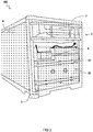
- FIG 1 shows a schematic perspective bird's eye view of an embodiment of a freight container 100.
- the container 100 is suitable for transporting cargo 5, especially temperature sensitive cargo.
- a freight container may also be referred to as an intermodal container, shipping container, e.g. a refrigerated container or a so-called reefer.
- the container which preferably can be an intermodal container and/or an ISO container, can be arranged for intermodal freight transport which can involve the use of multiple modes of transportation, e.g. including rail transportation, transportation by truck, and/or ship transportation, without any handling of the freight itself when changing modes of transportation.
- intermodal containers can be stacked up to seven units high. For instance therefore, the intermodal container can be arranged to be stackable, e.g.
- the container can be sufficiently strong and/or can be provided with bottom and top fittings, especially twistlock fittings.
- the container can be a so-called multimodal transport container, and may be arranged for multimodal transport, or so-called combined transport, wherein the transportation of goods can be under a single contract, but can nevertheless be performed wit at least two different means of transport, e.g. rail, sea and/or road.
- the container 100 comprises a container body 24 enclosing a cargo space 25 for storing the cargo 5.
- the container further comprises an air conditioning unit 7 arranged for controlling a temperature and/or humidity in the cargo space 25. Part the air conditioning unit 7 is suspended above a cargo floor 3 of the cargo space 25 for allowing cargo to be placed on the cargo floor 3 below the said part of the air conditioning unit 7.
- the container 100 comprises a generator (not shown) for powering the air conditioning unit 7.
- the generator may be external, or integrated into the air conditioning unit 7.
- the generator may be coupled to a fuel tank (not shown here) for supplying the generator with fuel, typically diesel.
- the generator may be powered by other means, e.g. electricity
- At least the outer length of the container corresponds with the sizes and dimensions of a standard freight container, especially a 45 foot container.
- the container is formed as a 45 foot container, preferably as a so-called 45 ft. pallet wide container.
- the cargo floor 3 is at least 2.4 meter wide and at least 13.2 meter long, such as to accommodate at least 33 Euro-pallets, e.g. stored in the manner shown in FIG 1 .
- the part of the air conditioning system 7 located above the cargo floor 3 is extending above the cargo floor for at most about 0.8 meter, it can be advantageous to place the first Euro-pallets with their longitudinal direction (e.g. two time 120 cm) extending in the width direction of the container (240 cm), such that only the loading height of two pallets (in stead of that of three 3 pallets) is restricted by said part of the air conditioning system located above the cargo floor.
- their longitudinal direction e.g. two time 120 cm
- the width direction of the container 240 cm
- the container is provided with first fitting blocks of which the mutual spacing corresponds to the mutual spacing of a 40 foot container and/or second fitting blocks or so-called corner fittings of which the mutual spacing corresponds to the mutual spacing of the outermost placed fitting blocks of a 45 foot container.
- FIG 2 shows a cross-section side view of a front of another embodiment of the container 100 including cargo 5 place inside the cargo space 25.
- the air conditioning unit 7 is arranged at or near a front side 1 of the container 100. This may be opposite a back side provided with one or more doors (not shown). In another or further embodiment, at least a part of the air conditioning system is provided against or near a top side 2 of the container 100.
- the container body 24 comprises a cavity 17 protruding inward into the container.
- at least part of the air conditioning unit 7 is sticking out from the container body 24 and accommodated in the cavity 17.
- a condenser part 7a of the air conditioning unit 7 may stick outside the container body 24 while an evaporator part 7b sticks inside the container body 24, in particular into the cargo space 25.
- the cavity 17 is formed by an inward step of the container body 24 on the upper front side 1,2 of the container 100.
- the cargo floor 3 extends below the step for allowing cargo 5 to be placed on the cargo floor 3 below the step.
- a sheet or sail 23 is provide at an outlet of the air conditioning unit 7 in the cargo space 25.
- the cool air from the air conditioning unit 7 may be distributed over the cargo space 25.
- the air conditioning unit 7 is arranged at least partially above the fuel tank 20.
- part of the condenser 7a is above the fuel tank 20.
- the fuel tank 20 is arranged flat against an outer hull of the container. By providing a relatively flat fuel tank, cargo space 25 inside the container body 24 may be further increased.
- the container and/or air conditioning unit 7 comprises a sensor (not shown), e.g. a temperature sensor.
- the sensor may be associated with the cargo space.
- a controller is provided for controlling the air conditioning system.
- the controller is arranged for determining whether an air property sensed by the sensor needs to be altered by examining whether the sensed air property is below a predetermined bottom threshold value and/or above a predetermined top threshold value.
- the controller may be arranged for controlling the air conditioning unit such as to alter the air property accordingly.
- the container 100 comprises a separation wall being located at a distal end of the cargo floor and separating the cargo space at least partly from a second part of the air conditioning system located behind said wall.
- the said wall defines a cavity for guiding air from the cargo space to the air conditioning unit or vice versa.
- FIG 3 shows a schematic perspective drawing of the front part of the embodiment, e.g. similar to FIG 2 .
- the container 100 comprises a battery 9 for feeding the air conditioning unit, a generator (not specifically indicated), especially a diesel powered generator, for charging the battery at least partly, and a fuel tank 20 for supplying the generator with fuel.
- the container 100 comprises a battery 9 for feeding the air conditioning unit 7 and/or starting the generator.
- the battery is arranged to be charged by the generator.
- the fuel tank 20 comprises an L-shape, wherein the battery 9 is accommodate in a cavity formed by the L-shape.
- This in combination with the suspended air conditioning unit 7, may provide a maximum capacity to the fuel tank 20 while allowing the placement of a battery 9, and without sacrificing cargo space.
- the container 100 as described herein, or otherwise comprises a clock and a controller arranged for controlling the generator in order to charge the battery 9 at least partly at a moment when a predetermined time interval has lapsed since the last time the battery is charged at least partly.
- the container 100 comprises a voltage sensing device and a controller arranged for controlling the generator in order to charge the battery at least partly at a moment when is determined that the terminal voltage of the battery has dropped below a predetermined minimum voltage threshold value.
- the container further comprises a receiver 21 and a controller arranged for controlling the generator in order to charge the battery at least partly based on a control signal received by said receiver.
- the figure may illustrate a method for transporting cargo, especially temperature sensitive cargo, by means of a freight container.
- the method comprises providing a freight container, preferably a container 100 as described herein, said container being provided with at least an air conditioning unit 7, preferably a cooling and/or heating unit, a battery 9, and a generator, especially a diesel powered generator.
- the method comprises sensing an air property of air inside the container, especially the temperature of air inside the container.
- the method comprises determining whether said air property needs to be altered by examining whether the sensed air property is below a predetermined bottom threshold value and/or above a predetermined top threshold value.
- the method comprises altering said air property when the value of the sensed air property is below said predetermined bottom threshold value, such as to bring said air property above said predetermined bottom threshold value, or altering said air property when the sensed value of the air property is above said predetermined top threshold value, such as to bring said air property below said predetermined top threshold value.
- the method comprises at least partly charging the battery 9 by means of the generator at a moment when there is no need to alter the air property of the air inside 25 the container.
- the step of charging the battery 9 at a moment when there is no need to alter the air property of the air inside 25 the container is initiated when a predetermined time interval has lapsed, e.g. when a predetermined time interval has lapsed since the last time the battery 9 is charged at least partly.
- the step of charging the battery 9 at a moment when there is no need to alter the air property of the air inside the container 100 is initiated when it is determined that the terminal voltage of the battery has dropped below a predetermined minimum voltage threshold value.
- the freight container 100 is provided with a receiver 21, e.g. on a top side 2 of the container as shown in FIG 6 .
- a receiver 21 e.g. on a top side 2 of the container as shown in FIG 6 .
- the step of charging the battery 9 at a moment when there is no need to alter the air property of the air inside the container can be initiated by means of a control signal received by said receiver of the freight container.
- the method comprises the step of altering the air property of the air inside the container while the battery is charged at the moment when the air property does not need to be altered.
- the method comprises the step of at least partly charging the battery by means of the generator at a moment when there is a need to alter the air property of the air inside the container.
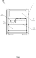
- FIG 4 shows a schematic front view of an embodiment of the embodiment, e.g. similar to FIG 2 and 3 .
- the container 100 comprises on the front side 1, an air conditioning unit 7, a fuel tank 20, and a battery 9.
- the fuel tank 20 may be held fixed by belts 22.
- FIG 5 shows a schematic view of the side 8 of an embodiment of the container 100, e.g. similar to FIGs 2-4 .
- the container 100 comprises an air conditioning unit 7 at or near the ceiling 2 of the container.
- the fuel tank 20 is arranged at the front side. As shown, the fuel tank 20 may be protected by extended corners 6. Also shown in this figure is the floor 3 at the bottom 4 of the container.
- FIG 6 shows a schematic view of the top 2 of the embodiment, e.g. similar to FIGs 2-5 .
- the top view shows for example a roster 11, which may function as an outlet for the air conditioning unit (not visible here).
- an optional transceiver 21 which may be used for receiving instructions and/or sending a status/location of the container or air conditioning unit.
- the top view shows an optional solar panel 10, which may be used to power equipment in the container.
- the solar panel 10 may be used to charge the battery (not shown here).
- FIG 7 shows a schematic perspective view of an embodiment of a fuel tank 20, e.g. as used in FIGs 2-6 .
- the L-shape of the tank 20 may be advantageous to accommodate equipment, e.g. a battery.
- the fuel tank 20 comprises a number of holes or tubes extending into the fuel tank. These may be advantageous e.g. to prevent or diminish slushing of the fuel inside the tank.
- the air conditioning unit may also provide heating when necessary.
- the air conditioning unit may also provide other environmental control, e.g. humidity control.
- embodiments were shown for a specifically arranged air conditioning unit, also alternative ways may be envisaged by those skilled in the art having the benefit of the present disclosure for achieving a similar or equivalent function and result.
- components such as the air conditioning unit, generator, battery, and/or fuel tank may be combined or split up into one or more alternative components.
- the various elements of the embodiments as discussed and shown offer certain advantages, such providing an air conditioned cargo space having maximizes capacity.
- any one of the above embodiments or processes may be combined with one or more other embodiments or processes to provide even further improvements in finding and matching designs and advantages.
- this disclosure offers particular advantages to transport of temperature sensitive cargo, and in general can be applied for any application wherein a maximum storage capacity for a climate controlled cargo container is desired.
Description
- The present disclosure relates to a freight container for transporting cargo, especially temperature sensitive cargo. The disclosure further relates to a method for transporting cargo.
- Modern society has become increasingly dependent on the long distance transport of cargo. Freight containers are widely used to transport such cargo, e.g. by boat, train, and/or truck. Some cargo, e.g. food, such as fruit, dairy products, meat, etc., but also electronics, may require a climate controlled environment to prevent their deterioration. Temperature and/or humidity sensitive cargo can be transported by a freight container comprising an air conditioning unit. For example, the air conditioning unit can be integrated into the container. To guarantee continuous temperature control, it is desirable to also integrate a power source/generator into the container or air conditioning unit. For example a diesel powered generator and fuel tank can be integrated into the container. However, the extra equipment may affect the available cargo space because the outer dimensions of the container are constrained by international standards. For example, a long range transport container may contain a relatively large fuel tank that occupies part of the cargo space. However, such a design runs counter to the general need for maximizing the cargo capacity of the freight container.
- Therefore, a general need exists for a long range, climate controlled freight container or reefer having an increased cargo capacity. For example, a specific need exists to have sufficient cargo capacity to transport thirty-three or more Euro pallets (each with a size of 80 cm x 120 cm) arranged side by side, while keeping climate control for a journey lasting twenty days or more.
- International patent application publication
WO 92/20 542 - United States patent application publication
US 2009/0 299 534 discloses an environmentally controlled shipping container including a storage space and a refrigeration system that includes a prime mover, a compressor driven by the prime mover and providing a flow of refrigerant, a condenser that receives the flow of refrigerant, and an evaporator in heat exchange relation with the storage space, wherein a controller operates the refrigeration system in one of: a continuous mode in which the prime mover operates continuously; a standard start/stop mode; and a modulated start/stop mode in which the operating parameters of the refrigeration system may be modulated. DocumentDE10 2011 105 475 A1 discloses an interchangeable container having an air conditioning unit placed above a cargo floor of a cargo space. DocumentUS 2,635,432 discloses a self-contained refrigerating freight car unit having an air conditioning unit place above a cargo floor of a cargo space. - To meet these or other challenges, one aspect of the present disclosure provides a freight container for transporting cargo, especially temperature sensitive cargo. The container comprises a container body enclosing a cargo space for storing the cargo. The container further comprises an air conditioning unit arranged for controlling a temperature and/or humidity in the cargo space. It is noted that the air conditioning unit may for instance be arranged for conditioning the temperature of air in the container, e.g. in order to facilitate that the temperature of goods transported by the container can be kept substantially below a predetermined maximum temperature and/or can be kept substantially above a predetermined minimum temperature, preferably said temperature can be kept substantially within a predetermined temperature range. For example, the air conditioning unit can be arranged for cooling air and/or can be arranged for heating air. The container further comprises a generator for powering the air conditioning unit. The container further comprises a fuel tank for supplying the generator with fuel, especially diesel. Part the air conditioning unit is suspended above a cargo floor of the cargo space and the air conditioning unit is arranged partially above the fuel tank. Advantageously, the present arrangement may allow cargo to be placed on the cargo floor below the air conditioning system. By arranging the air conditioning unit at or near a front side of the container opposite a back side provided with one or more doors, the unit can be placed against the front without affecting the doors. For example, at least a part of the air conditioning system can be provided against a top side of the container. By providing an outside of the container body with a cavity protruding inward into the container and accommodating at least part of the air conditioning unit in the cavity, the outer dimensions of the container can be kept within specification, while saving cargo space at least at the floor level. For example, a part of the air conditioning unit, e.g. condenser, may be sticking outside from the container body. By shaping the cavity as an inward step of the container body on the upper front side of the container, the air conditioning unit can be placed through a vertical side wall, yet stay within the constrained perimeter of the container. Advantageously, the cargo floor may extends below the step for allowing cargo to be placed on the cargo floor below the step.
- In one aspect, the design made available by the present disclosure can provide a container having an outer length corresponding with the sizes and dimensions of a standard freight container. For example, the freight container can be formed as a 45 foot container, preferably as a so-called 45 ft. pallet wide container. A relevant norm for the standard container dimensions would for example be an ISO standard, such as ISO 668 (1995) or an equivalent standard. The present design allows for a cargo floor that is at least 2.4 meter wide and at least 13.2 meter long, such as to accommodate at least 33 Euro-pallets or EPAL-pallets on the floor (each pallet typically has width x length = 80 cm x 120 cm). For example, 11 rows of 3 pallets (having their longitudinal direction extending in the longitudinal direction of the container/cargo floor) Alternatively, 1 row of 3 pallets (having their longitudinal direction extending in the longitudinal direction of the container/cargo floor) and 15 rows of 2 + 1 * 3 pallets having their longitudinal direction extending in the width direction of the container/cargo floor). The container can be provided with first fitting blocks of which the mutual spacing corresponds to the mutual spacing of a 40 foot container and/or second fitting blocks or so-called corner fittings of which the mutual spacing corresponds to the mutual spacing of the outermost placed fitting blocks of a 45 foot container. The air conditioning unit is arranged partially above the fuel tank, for instance to save further space. For example, the fuel tank can be arranged flat against an outer hull of the container. Further space can be saved by integrating components. For example the generator can be integrated as part of the air conditioning unit. Alternatively, or in addition to the generator, the container may comprise one or more batteries for feeding the air conditioning unit and/or starting the generator. Advantageously, the battery can be charged by the generator. To save further space, the fuel tank may comprises an L-shape, wherein the battery is accommodated in a cavity formed by the L-shape.
- The container may comprise a sensor, especially a temperature sensor, associated with the cargo space, and a controller for controlling the air conditioning system. For example, the controller is arranged for determining whether an air property sensed by the sensor needs to be altered by examining whether the sensed air property is below a predetermined bottom threshold value and/or above a predetermined top threshold value, and for controlling the air conditioning unit such as to alter the air property accordingly.
- Another or further problem associated with containers for transporting temperature sensitive cargo is that the batteries of such containers can run low, especially when the containers are transported through relatively cold areas with a relatively cold outdoor temperature (e.g. when being transported overland, for instance by train, e.g. from Europe through Russia to China, or vice versa).
- Accordingly, in another or further aspect, the present disclosure provides a freight container for transporting cargo, especially temperature sensitive cargo as described above, or otherwise. The container comprises a cargo space defining a cargo floor, and an air conditioning unit, preferably a cooling and/or heating unit, a battery for feeding the air conditioning unit, a generator, especially a diesel powered generator, for charging the battery at least partly, and a fuel tank for supplying the generator with fuel. The container further comprises a clock and a controller arranged for controlling the generator in order to charge the battery at least partly at a moment when a predetermined time interval has lapsed since the last time the battery is charged at least partly. Alternatively, or in addition, the container further comprises a voltage sensing device and a controller arranged for controlling the generator in order to charge the battery at least partly at a moment when is determined that the terminal voltage of the battery has dropped below a predetermined minimum voltage threshold value. Alternatively, or in addition, the container further comprises a receiver and a controller arranged for controlling the generator in order to charge the battery at least partly based on a control signal received by said receiver.
- By providing a wall separating the cargo space from a part of the air conditioning system located behind said wall, said wall can define a cavity for guiding air from the cargo space to the air conditioning unit or vice versa.
- In a further aspect, the present disclosure provides a method for transporting cargo, especially temperature sensitive cargo, by means of a freight container. The method comprises providing a freight container, preferably a container as described herein. The container is provided with at least an air conditioning unit, preferably a cooling and/or heating unit. The container is further provided with a battery and a generator, especially a diesel powered generator. The method further comprises sensing an air property of air inside the container, especially the temperature of air inside the container. The method further comprises determining whether said air property needs to be altered by examining whether the sensed air property is below a predetermined bottom threshold value and/or above a predetermined top threshold value. The method further comprises altering said air property when the value of the sensed air property is below said predetermined bottom threshold value, such as to bring said air property above said predetermined bottom threshold value, or altering said air property when the sensed value of the air property is above said predetermined top threshold value, such as to bring said air property below said predetermined top threshold value. The method further comprises at least partly charging the battery by means of the generator at a moment when there is no need to alter the air property of the air inside the container. This may be advantageous for keeping the battery charged also during periods when the air conditioning is not strictly necessary. Otherwise, the battery may discharge which may also prevent the generator from starting.
- In one embodiment, the step of charging the battery at a moment when there is no need to alter the air property of the air inside the container is initiated when a predetermined time interval has lapsed, e.g. when a predetermined time interval has lapsed since the last time the battery is charged at least partly. In another or further embodiment, the step of charging the battery at a moment when there is no need to alter the air property of the air inside the container is initiated when it is determined that the terminal voltage of the battery has dropped below a predetermined minimum voltage threshold value. In another or further embodiment, the freight container further is provided with a receiver, and wherein the step of charging the battery at a moment when there is no need to alter the air property of the air inside the container is initiated by means of a control signal received by said receiver of the freight container. In one embodiment, the air conditioning unit is activated while the air property does not need to be altered based e.g. on temperature. Alternatively, or in addition, the battery can be at least partly charged by means of the generator at a moment when there is a need to alter the air property of the air inside the container.
- These and other features, aspects, and advantages of the apparatus, systems and methods of the present disclosure will become better understood from the following description, appended claims, and accompanying drawing wherein:
-
FIG 1 shows a schematic perspective bird's eye view of an embodiment of a container; -
FIG 2 shows a cross-section side view of a front of another embodiment of the container including placement of cargo; -
FIG 3 shows a schematic perspective drawing of the front part of the embodiment; -
FIG 4 shows a schematic front view of an embodiment of the embodiment; -
FIG 5 shows a schematic side view of an embodiment of the embodiment; -
FIG 6 shows a schematic top view of an embodiment of the embodiment; -
FIG 7 shows a schematic perspective view of an embodiment of a fuel tank. - Unless otherwise defined, all terms (including technical and scientific terms) used herein have the same meaning as commonly understood by one of ordinary skill in the art to which this invention belongs as read in the context of the description and drawings. It will be further understood that terms, such as those defined in commonly used dictionaries, should be interpreted as having a meaning that is consistent with their meaning in the context of the relevant art and will not be interpreted in an idealized or overly formal sense unless expressly so defined herein. In some instances, detailed descriptions of well-known devices and methods may be omitted so as not to obscure the description of the present systems and methods. Terminology used for describing particular embodiments is not intended to be limiting of the invention. As used herein, the singular forms "a", "an" and "the" are intended to include the plural forms as well, unless the context clearly indicates otherwise. The term "and/or" includes any and all combinations of one or more of the associated listed items. It will be understood that the terms "comprises" and/or "comprising" specify the presence of stated features but do not preclude the presence or addition of one or more other features. It will be further understood that when a particular step of a method is referred to as subsequent to another step, it can directly follow said other step or one or more intermediate steps may be carried out before carrying out the particular step, unless specified otherwise. Likewise it will be understood that when a connection between structures or components is described, this connection may be established directly or through intermediate structures or components unless specified otherwise. All publications, patent applications, patents, and other references mentioned herein are incorporated by reference in their entirety. In case of conflict, the present specification, including definitions, will control.
- The invention is described more fully hereinafter with reference to the accompanying drawings, in which embodiments of the invention are shown. This invention may, however, be embodied in many different forms and should not be construed as limited to the embodiments set forth herein. Rather, these embodiments are provided so that this disclosure will be thorough and complete, and will fully convey the scope of the invention to those skilled in the art. The description of the exemplary embodiments is intended to be read in connection with the accompanying drawings, which are to be considered part of the entire written description. In the drawings, the absolute and relative sizes of systems, components, layers, and regions may be exaggerated for clarity. Embodiments may be described with reference to schematic and/or cross-section illustrations of possibly idealized embodiments and intermediate structures of the invention. Relative terms as well as derivatives thereof should be construed to refer to the orientation as then described or as shown in the drawing under discussion. These relative terms are for convenience of description and do not require that the system be constructed or operated in a particular orientation unless these relative terms (e.g. above) are present in the claims which define the scope of protection. In the description and drawings, like numbers refer to like elements throughout. In particular, the following reference numbers may apply: 1 container front, 2 container ceiling, 3 cargo floor, 4 container bottom, 5 cargo, 6 corner pieces, 7 cooler, 8 container side, 9 battery, 10 solar panels, 11 cooler gate, 13 reinforced holes, 20 fuel tank, 21 remote control, 22 belt, 23 distribution sheet, 24 container body, 25 cargo space, 100 container.
-
FIG 1 shows a schematic perspective bird's eye view of an embodiment of afreight container 100. Thecontainer 100 is suitable for transportingcargo 5, especially temperature sensitive cargo. A freight container may also be referred to as an intermodal container, shipping container, e.g. a refrigerated container or a so-called reefer. The container, which preferably can be an intermodal container and/or an ISO container, can be arranged for intermodal freight transport which can involve the use of multiple modes of transportation, e.g. including rail transportation, transportation by truck, and/or ship transportation, without any handling of the freight itself when changing modes of transportation. Typically, on board ships, intermodal containers can be stacked up to seven units high. For instance therefore, the intermodal container can be arranged to be stackable, e.g. can be sufficiently strong and/or can be provided with bottom and top fittings, especially twistlock fittings. The container can be a so-called multimodal transport container, and may be arranged for multimodal transport, or so-called combined transport, wherein the transportation of goods can be under a single contract, but can nevertheless be performed wit at least two different means of transport, e.g. rail, sea and/or road. - According to the embodiment shown, the
container 100 comprises acontainer body 24 enclosing acargo space 25 for storing thecargo 5. The container further comprises anair conditioning unit 7 arranged for controlling a temperature and/or humidity in thecargo space 25. Part theair conditioning unit 7 is suspended above acargo floor 3 of thecargo space 25 for allowing cargo to be placed on thecargo floor 3 below the said part of theair conditioning unit 7. In another or further embodiment, thecontainer 100 comprises a generator (not shown) for powering theair conditioning unit 7. For example, the generator may be external, or integrated into theair conditioning unit 7. The generator may be coupled to a fuel tank (not shown here) for supplying the generator with fuel, typically diesel. Alternatively, or in addition, the generator may be powered by other means, e.g. electricity - In one embodiment, at least the outer length of the container corresponds with the sizes and dimensions of a standard freight container, especially a 45 foot container. In another or further embodiment, the container is formed as a 45 foot container, preferably as a so-called 45 ft. pallet wide container. In one embodiment, the
cargo floor 3 is at least 2.4 meter wide and at least 13.2 meter long, such as to accommodate at least 33 Euro-pallets, e.g. stored in the manner shown inFIG 1 . - For example, in case the part of the
air conditioning system 7 located above thecargo floor 3 is extending above the cargo floor for at most about 0.8 meter, it can be advantageous to place the first Euro-pallets with their longitudinal direction (e.g. two time 120 cm) extending in the width direction of the container (240 cm), such that only the loading height of two pallets (in stead of that of three 3 pallets) is restricted by said part of the air conditioning system located above the cargo floor. - In one embodiment (not shown here), the container is provided with first fitting blocks of which the mutual spacing corresponds to the mutual spacing of a 40 foot container and/or second fitting blocks or so-called corner fittings of which the mutual spacing corresponds to the mutual spacing of the outermost placed fitting blocks of a 45 foot container.
-
FIG 2 shows a cross-section side view of a front of another embodiment of thecontainer 100 includingcargo 5 place inside thecargo space 25. - In one embodiment, e.g. as shown, the
air conditioning unit 7 is arranged at or near afront side 1 of thecontainer 100. This may be opposite a back side provided with one or more doors (not shown). In another or further embodiment, at least a part of the air conditioning system is provided against or near atop side 2 of thecontainer 100. - In one embodiment, e.g. as shown, the
container body 24 comprises acavity 17 protruding inward into the container. In another or further embodiment at least part of theair conditioning unit 7 is sticking out from thecontainer body 24 and accommodated in thecavity 17. For example, acondenser part 7a of theair conditioning unit 7 may stick outside thecontainer body 24 while anevaporator part 7b sticks inside thecontainer body 24, in particular into thecargo space 25. In another or further embodiment, e.g. as shown, thecavity 17 is formed by an inward step of thecontainer body 24 on the upperfront side container 100. In another or further embodiment, e.g. as shown, thecargo floor 3 extends below the step for allowingcargo 5 to be placed on thecargo floor 3 below the step. - In one embodiment, a sheet or sail 23 is provide at an outlet of the
air conditioning unit 7 in thecargo space 25. By arranging thesheet 23, as shown suspended at thetop side 2 of thecontainer 100, the cool air from theair conditioning unit 7 may be distributed over thecargo space 25. - In one embodiment, e.g. as shown, the
air conditioning unit 7 is arranged at least partially above thefuel tank 20. For example, in the embodiment shown, part of thecondenser 7a is above thefuel tank 20. In another or further embodiment, e.g. as shown, thefuel tank 20 is arranged flat against an outer hull of the container. By providing a relatively flat fuel tank,cargo space 25 inside thecontainer body 24 may be further increased. - In one embodiment, the container and/or
air conditioning unit 7 comprises a sensor (not shown), e.g. a temperature sensor. The sensor may be associated with the cargo space. In another or further embodiment a controller is provided for controlling the air conditioning system. For example, the controller is arranged for determining whether an air property sensed by the sensor needs to be altered by examining whether the sensed air property is below a predetermined bottom threshold value and/or above a predetermined top threshold value. The controller may be arranged for controlling the air conditioning unit such as to alter the air property accordingly. - In one embodiment, the
container 100 comprises a separation wall being located at a distal end of the cargo floor and separating the cargo space at least partly from a second part of the air conditioning system located behind said wall. In the embodiment, the said wall defines a cavity for guiding air from the cargo space to the air conditioning unit or vice versa. -
FIG 3 shows a schematic perspective drawing of the front part of the embodiment, e.g. similar toFIG 2 . In one embodiment, e.g. as shown, thecontainer 100 comprises abattery 9 for feeding the air conditioning unit, a generator (not specifically indicated), especially a diesel powered generator, for charging the battery at least partly, and afuel tank 20 for supplying the generator with fuel. In one embodiment, e.g. as shown, thecontainer 100 comprises abattery 9 for feeding theair conditioning unit 7 and/or starting the generator. In one embodiment, the battery is arranged to be charged by the generator. - In one embodiment, e.g. as shown, the
fuel tank 20 comprises an L-shape, wherein thebattery 9 is accommodate in a cavity formed by the L-shape. This, in combination with the suspendedair conditioning unit 7, may provide a maximum capacity to thefuel tank 20 while allowing the placement of abattery 9, and without sacrificing cargo space. - In one embodiment, the
container 100 as described herein, or otherwise, comprises a clock and a controller arranged for controlling the generator in order to charge thebattery 9 at least partly at a moment when a predetermined time interval has lapsed since the last time the battery is charged at least partly. Alternatively, or in addition, thecontainer 100 comprises a voltage sensing device and a controller arranged for controlling the generator in order to charge the battery at least partly at a moment when is determined that the terminal voltage of the battery has dropped below a predetermined minimum voltage threshold value. Alternatively, or in addition, the container further comprises areceiver 21 and a controller arranged for controlling the generator in order to charge the battery at least partly based on a control signal received by said receiver. - In another or further aspect of the disclosure, the figure may illustrate a method for transporting cargo, especially temperature sensitive cargo, by means of a freight container. In one embodiment, the method comprises providing a freight container, preferably a
container 100 as described herein, said container being provided with at least anair conditioning unit 7, preferably a cooling and/or heating unit, abattery 9, and a generator, especially a diesel powered generator. In another or further embodiment, the method comprises sensing an air property of air inside the container, especially the temperature of air inside the container. In another or further embodiment, the method comprises determining whether said air property needs to be altered by examining whether the sensed air property is below a predetermined bottom threshold value and/or above a predetermined top threshold value. In another or further embodiment, the method comprises altering said air property when the value of the sensed air property is below said predetermined bottom threshold value, such as to bring said air property above said predetermined bottom threshold value, or altering said air property when the sensed value of the air property is above said predetermined top threshold value, such as to bring said air property below said predetermined top threshold value. In another or further embodiment, the method comprises at least partly charging thebattery 9 by means of the generator at a moment when there is no need to alter the air property of the air inside 25 the container. - In one embodiment, the step of charging the
battery 9 at a moment when there is no need to alter the air property of the air inside 25 the container is initiated when a predetermined time interval has lapsed, e.g. when a predetermined time interval has lapsed since the last time thebattery 9 is charged at least partly. - In one embodiment, the step of charging the
battery 9 at a moment when there is no need to alter the air property of the air inside thecontainer 100 is initiated when it is determined that the terminal voltage of the battery has dropped below a predetermined minimum voltage threshold value. - In one embodiment, the
freight container 100 is provided with areceiver 21, e.g. on atop side 2 of the container as shown inFIG 6 . For example the step of charging thebattery 9 at a moment when there is no need to alter the air property of the air inside the container can be initiated by means of a control signal received by said receiver of the freight container. - In one embodiment, the method comprises the step of altering the air property of the air inside the container while the battery is charged at the moment when the air property does not need to be altered.
- In one embodiment, the method comprises the step of at least partly charging the battery by means of the generator at a moment when there is a need to alter the air property of the air inside the container.
-
FIG 4 shows a schematic front view of an embodiment of the embodiment, e.g. similar toFIG 2 and3 . In the embodiment shown, thecontainer 100 comprises on thefront side 1, anair conditioning unit 7, afuel tank 20, and abattery 9. Thefuel tank 20 may be held fixed bybelts 22. -
FIG 5 shows a schematic view of theside 8 of an embodiment of thecontainer 100, e.g. similar toFIGs 2-4 . As visible in this view, thecontainer 100 comprises anair conditioning unit 7 at or near theceiling 2 of the container. Thefuel tank 20 is arranged at the front side. As shown, thefuel tank 20 may be protected byextended corners 6. Also shown in this figure is thefloor 3 at thebottom 4 of the container. -
FIG 6 shows a schematic view of thetop 2 of the embodiment, e.g. similar toFIGs 2-5 . The top view shows for example a roster 11, which may function as an outlet for the air conditioning unit (not visible here). Also shown on the top side is anoptional transceiver 21, which may be used for receiving instructions and/or sending a status/location of the container or air conditioning unit. Finally, the top view shows an optionalsolar panel 10, which may be used to power equipment in the container. For example, thesolar panel 10 may be used to charge the battery (not shown here). -
FIG 7 shows a schematic perspective view of an embodiment of afuel tank 20, e.g. as used inFIGs 2-6 . The L-shape of thetank 20 may be advantageous to accommodate equipment, e.g. a battery. In the embodiment shown, thefuel tank 20 comprises a number of holes or tubes extending into the fuel tank. These may be advantageous e.g. to prevent or diminish slushing of the fuel inside the tank. - For the purpose of clarity and a concise description, features are described herein as part of the same or separate embodiments, however, it will be appreciated that the scope of the invention may include embodiments having combinations of all or some of the features described. Alternative, or in addition to providing a cooling function, the air conditioning unit may also provide heating when necessary. Alternatively, or in addition, the air conditioning unit may also provide other environmental control, e.g. humidity control. For example, while embodiments were shown for a specifically arranged air conditioning unit, also alternative ways may be envisaged by those skilled in the art having the benefit of the present disclosure for achieving a similar or equivalent function and result.
- E.g. components such as the air conditioning unit, generator, battery, and/or fuel tank may be combined or split up into one or more alternative components. The various elements of the embodiments as discussed and shown offer certain advantages, such providing an air conditioned cargo space having maximizes capacity. Of course, it is to be appreciated that any one of the above embodiments or processes may be combined with one or more other embodiments or processes to provide even further improvements in finding and matching designs and advantages. It is appreciated that this disclosure offers particular advantages to transport of temperature sensitive cargo, and in general can be applied for any application wherein a maximum storage capacity for a climate controlled cargo container is desired.
- While the present systems and methods have been described in particular detail with reference to specific exemplary embodiments thereof, it should also be appreciated that numerous modifications and alternative embodiments may be devised by those having ordinary skill in the art without departing from the scope of the present disclosure. For example, embodiments wherein devices or systems are disclosed to be arranged and/or constructed for performing a specified method or function inherently disclose the method or function as such and/or in combination with other disclosed embodiments of methods or systems. Furthermore, embodiments of methods are considered to inherently disclose their implementation in respective hardware, where possible, in combination with other disclosed embodiments of methods or systems. Furthermore, methods that can be embodied as program instructions, e.g. on a non-transient computer-readable storage medium, are considered inherently disclosed as such embodiment.
- Finally, the above-discussion is intended to be merely illustrative of the present systems and/or methods and should not be construed as limiting the appended claims to any particular embodiment or group of embodiments. The specification and drawings are accordingly to be regarded in an illustrative manner and are not intended to limit the scope of the appended claims. In interpreting the appended claims, it should be understood that the word "comprising" does not exclude the presence of other elements or acts than those listed in a given claim; the word "a" or "an" preceding an element does not exclude the presence of a plurality of such elements; any reference signs in the claims do not limit their scope; several "means" may be represented by the same or different item(s) or implemented structure or function; any of the disclosed devices or portions thereof may be combined together or separated into further portions unless specifically stated otherwise. The mere fact that certain measures are recited in mutually different claims does not indicate that a combination of these measures cannot be used to advantage. In particular, all working combinations of the claims are considered inherently disclosed.
Claims (15)
- Freight container (100) for transporting cargo (5), especially temperature sensitive cargo, the container (100) comprising:- a container body (24) enclosing a cargo space (25) for storing the cargo (5);- an air conditioning unit (7), preferably a cooling and/or heating unit (7), arranged for controlling a temperature and/or humidity in the cargo space (25);- a generator for powering the air conditioning unit (7); and- a fuel tank (20) for supplying the generator with fuel, especially diesel; characterised in that- the air conditioning unit (7) is arranged partially above the fuel tank (20) and in that part of the air conditioning unit (7) is suspended above a cargo floor (3) of the cargo space (25) for allowing cargo to be placed on the cargo floor (3) below the said part of the air conditioning unit (7).
- Freight container according to claim 1, wherein the container is an intermodal container or a so-called multimodal transport container, especially an ISO container.
- Freight container according to claim 1 or 2, wherein the air conditioning unit (7) is arranged at or near a front side (1) of the container (100) opposite a back side provided with one or more doors.
- Freight container according to any one of the preceding claims,
wherein an outside of the container body (24) comprises a cavity (17) protruding inward into the container, and at least part of the air conditioning unit (7) is sticking out from the container body (24) and accommodated in the cavity (17),
preferably wherein the cavity (17) is formed by an inward step of the container body (24) on the upper front side (1,2) of the container (100),
more preferably wherein the cargo floor (3) extends below the step for allowing cargo (5) to be placed on the cargo floor (3) below the step. - Freight container according to any one of the preceding claims, wherein the fuel tank (20) is arranged flat against an outer hull of the container.
- Freight container according to any one of the preceding claims, wherein the generator is part of the air conditioning unit (7).
- Freight container according to any one of the preceding claims, comprising a battery (9) for feeding the air conditioning unit (7) and/or starting the generator, the battery being arranged to be charged by the generator,
preferably wherein the fuel tank (20) comprises an L-shape, and the battery (9) is accommodated in a cavity formed by the L-shape. - Freight container according to any one of the preceding claims, wherein said at least a part of the air conditioning unit (7) is provided against a top side (2) of the container.
- Freight container according to any one of the preceding claims,
wherein at least the outer length of the freight container corresponds with the sizes and dimensions of a standard freight container, especially a 45 foot container, or wherein the freight container is formed as a 45 foot container, preferably as a so-called 45 ft. pallet wide container, or wherein the cargo floor (3) is at least 2.4 meter wide and at least 13.2 meter long, such as to accommodate at least 33 Euro-pallets. - Freight container according to any one of the preceding claims, wherein the container is provided with first fitting blocks of which the mutual spacing corresponds to the mutual spacing of a 40 foot container and/or second fitting blocks or so-called corner fittings of which the mutual spacing corresponds to the mutual spacing of the outermost placed fitting blocks of a 45 foot container.
- Freight container according to any one of the preceding claims, further comprising a sensor, especially a temperature sensor, associated with the cargo space, and a controller for controlling the air conditioning unit, wherein said controller is arranged for determining whether an air property sensed by the sensor needs to be altered by examining whether the sensed air property is below a predetermined bottom threshold value and/or above a predetermined top threshold value, and for controlling the air conditioning unit such as to alter the air property accordingly.
- Freight container according to any one of the preceding claims, comprising a battery (9) for feeding the air conditioning unit (7), wherein the generator, especially a diesel powered generator, is for charging the battery (9) at least partly,
wherein the container (100) further comprises a clock and a controller arranged for controlling the generator in order to charge the battery (9) at least partly at a moment when a predetermined time interval has lapsed since the last time the battery is charged at least partly, and/or
wherein the container (100) further comprises a voltage sensing device and a controller arranged for controlling the generator in order to charge the battery at least partly at a moment when is determined that the terminal voltage of the battery has dropped below a predetermined minimum voltage threshold value, and/or
wherein the container further comprises a receiver (21) and a controller arranged for controlling the generator in order to charge the battery at least partly based on a control signal received by said receiver. - Freight container according to any one of the preceding claims, further comprising a separation wall being located at a distal end of the cargo floor and separating the cargo space at least partly from a second part of the air conditioning unit (7) located behind said wall, wherein said wall defines a cavity for guiding air from the cargo space to the air conditioning unit or vice versa.
- Method for transporting cargo, especially temperature sensitive cargo, by means of a freight container, the method comprising:- providing a freight container (100) according to any one of the preceding claims;- sensing an air property of air inside the container, especially the temperature of air inside the container;- determining whether said air property needs to be altered by examining whether the sensed air property is below a predetermined bottom threshold value and/or above a predetermined top threshold value;- altering said air property when the value of the sensed air property is below said predetermined bottom threshold value, such as to bring said air property above said predetermined bottom threshold value, or altering said air property when the sensed value of the air property is above said predetermined top threshold value, such as to bring said air property below said predetermined top threshold value; and- at least partly charging the battery (9) by means of the generator at a moment when there is no need to alter the air property of the air inside (25) the container.
- Method according to claim 14,
wherein the step of charging the battery (9) at a moment when there is no need to alter the air property of the air inside (25) the container is initiated when a predetermined time interval has lapsed, e.g. when a predetermined time interval has lapsed since the last time the battery (9) is charged at least partly; or wherein the step of charging the battery (9) at a moment when there is no need to alter the air property of the air inside the container (100) is initiated when it is determined that the terminal voltage of the battery has dropped below a predetermined minimum voltage threshold value; and/or
wherein the freight container further is provided with a receiver (21), and wherein the step of charging the battery (9) at a moment when there is no need to alter the air property of the air inside the container is initiated by means of a control signal received by said receiver of the freight container; and/or
wherein the method further comprises the step of altering the air property of the air inside the container while the battery is charged at the moment when the air property does not need to be altered; and/or
wherein the method further comprises the step of at least partly charging the battery by means of the generator at a moment when there is a need to alter the air property of the air inside the container.
Priority Applications (6)
| Application Number | Priority Date | Filing Date | Title |
|---|---|---|---|
| RS20170985A RS56420B1 (en) | 2014-05-16 | 2015-05-08 | Freight container and method for transporting cargo |
| PL17179507T PL3284702T3 (en) | 2014-05-16 | 2015-05-08 | Freight container and method for transporting cargo |
| PL15729951T PL3142945T3 (en) | 2014-05-16 | 2015-05-08 | Freight container and method for transporting cargo |
| SI201530107T SI3142945T1 (en) | 2014-05-16 | 2015-05-08 | Freight container and method for transporting cargo |
| EP17179507.3A EP3284702B1 (en) | 2014-05-16 | 2015-05-08 | Freight container and method for transporting cargo |
| HRP20171465TT HRP20171465T1 (en) | 2014-05-16 | 2017-10-02 | Freight container and method for transporting cargo |
Applications Claiming Priority (3)
| Application Number | Priority Date | Filing Date | Title |
|---|---|---|---|
| CN201420250748.2U CN203959038U (en) | 2014-05-16 | 2014-05-16 | Extraordinary land route deep freezer |
| NL2012992A NL2012992C2 (en) | 2014-05-16 | 2014-06-12 | Freight container and method for transporting cargo. |
| PCT/NL2015/050322 WO2015174830A1 (en) | 2014-05-16 | 2015-05-08 | Freight container and method for transporting cargo |
Related Child Applications (1)
| Application Number | Title | Priority Date | Filing Date |
|---|---|---|---|
| EP17179507.3A Division EP3284702B1 (en) | 2014-05-16 | 2015-05-08 | Freight container and method for transporting cargo |
Publications (2)
| Publication Number | Publication Date |
|---|---|
| EP3142945A1 EP3142945A1 (en) | 2017-03-22 |
| EP3142945B1 true EP3142945B1 (en) | 2017-07-05 |
Family
ID=51919654
Family Applications (2)
| Application Number | Title | Priority Date | Filing Date |
|---|---|---|---|
| EP15729951.2A Active EP3142945B1 (en) | 2014-05-16 | 2015-05-08 | Freight container and method for transporting cargo |
| EP17179507.3A Active EP3284702B1 (en) | 2014-05-16 | 2015-05-08 | Freight container and method for transporting cargo |
Family Applications After (1)
| Application Number | Title | Priority Date | Filing Date |
|---|---|---|---|
| EP17179507.3A Active EP3284702B1 (en) | 2014-05-16 | 2015-05-08 | Freight container and method for transporting cargo |
Country Status (15)
| Country | Link |
|---|---|
| EP (2) | EP3142945B1 (en) |
| CN (3) | CN203959038U (en) |
| DE (1) | DE202015007754U1 (en) |
| DK (1) | DK3142945T3 (en) |
| EA (1) | EA029480B1 (en) |
| ES (1) | ES2643385T3 (en) |
| HR (1) | HRP20171465T1 (en) |
| HU (1) | HUE034917T2 (en) |
| LT (1) | LT3142945T (en) |
| NL (1) | NL2012992C2 (en) |
| PL (2) | PL3142945T3 (en) |
| PT (1) | PT3142945T (en) |
| RS (1) | RS56420B1 (en) |
| SI (1) | SI3142945T1 (en) |
| WO (1) | WO2015174830A1 (en) |
Families Citing this family (15)
| Publication number | Priority date | Publication date | Assignee | Title |
|---|---|---|---|---|
| CN203959038U (en) * | 2014-05-16 | 2014-11-26 | 单位45有限公司 | Extraordinary land route deep freezer |
| CN104803124B (en) * | 2015-03-03 | 2018-01-26 | 中集集团集装箱控股有限公司 | Container built in fuel tank |
| US11415367B2 (en) | 2016-06-17 | 2022-08-16 | Carrier Corporation | Mechanical subcooler with battery supplement |
| CN109416217A (en) * | 2016-06-17 | 2019-03-01 | 开利公司 | Battery system for refrigerated transport container |
| SG11201902937VA (en) | 2016-10-10 | 2019-05-30 | Carrier Corp | Method of stacking refrigerated shipping containers |
| DE102017203604A1 (en) | 2017-03-06 | 2018-09-06 | Thomas Gessner | System for storage, distribution and delivery of mobile containers and / or goods in containers with vehicles |
| CN108768045A (en) * | 2018-08-22 | 2018-11-06 | 中车长江车辆有限公司 | Railway dislocation generation is equipped |
| CN109353711B (en) * | 2018-12-27 | 2023-09-19 | 中车长江车辆有限公司 | refrigerated container |
| CN110002123A (en) * | 2019-04-26 | 2019-07-12 | 中铁第四勘察设计院集团有限公司 | A kind of high-speed rail logistics medical supplies transport machine for collecting load |
| CN110436066A (en) * | 2019-08-30 | 2019-11-12 | 中车长江车辆有限公司 | Frozen products insulated container |
| RU194769U1 (en) * | 2019-09-30 | 2019-12-23 | Общество с ограниченной ответственностью "Эксплуатация и ремонт вагонов и контейнеров" | REMOVABLE DEVICE FOR ELECTRICITY SUPPLY OF REFRIGERATOR CONTAINER ON RAILWAY PLATFORM |
| CN112918937A (en) * | 2019-12-05 | 2021-06-08 | 巴彦淖尔市蒙强科技节能有限公司 | Low-energy-consumption fresh-keeping warehouse utilizing solar energy to generate electricity |
| US11891236B2 (en) | 2020-02-25 | 2024-02-06 | Pvpallet, Inc. | Transport container |
| SE544334C2 (en) * | 2020-10-02 | 2022-04-12 | Envirotainer Eng Ab | Freight container comprising environmental sensors and method for sensing an environmental parameter |
| CN113998330A (en) * | 2021-11-05 | 2022-02-01 | 中车长江运输设备集团有限公司 | Refrigerated container front end structure and refrigerated container with same |
Citations (11)
| Publication number | Priority date | Publication date | Assignee | Title |
|---|---|---|---|---|
| US2635432A (en) | 1948-06-28 | 1953-04-21 | Dole Refrigerating Co | Self-contained refrigerating freight car unit |
| US3871188A (en) | 1973-09-07 | 1975-03-18 | Thermo King Corp | Demountable transportation refrigeration unit |
| WO1992020542A1 (en) | 1991-05-13 | 1992-11-26 | Reefco Manufacturing Corporation | Refrigerated container |
| US5739675A (en) | 1995-12-26 | 1998-04-14 | Carrier Corporation | Removable powertray for a self contained motor generator set |
| CN2622115Y (en) | 2003-05-30 | 2004-06-30 | 扬州通利冷藏集装箱有限公司 | Refrigerated container having concave-convex front part |
| WO2008079875A1 (en) | 2006-12-21 | 2008-07-03 | Thermo King Corporation | Heating system for transport refrigeration unit |
| CN101402413A (en) | 2007-10-17 | 2009-04-08 | 中国国际海运集装箱(集团)股份有限公司 | Front frame of refrigerated container |
| CN101501424A (en) | 2006-06-27 | 2009-08-05 | 洋马株式会社 | Refrigerating container |
| US20090299534A1 (en) | 2008-05-30 | 2009-12-03 | Thermo King Corporation | Start/stop temperature control operation |
| WO2011056642A2 (en) | 2009-10-27 | 2011-05-12 | Carrier Corporation | Hybrid refrigeration system for a mobile unit and method of operation |
| DE102011105475A1 (en) | 2011-06-24 | 2012-12-27 | Man Truck & Bus Ag | Interchangeable container for storage and transportation of e.g. temperature-sensitive goods in trailer, has power generator to supply electrical power to electrical load which is not component of cooling device |
Family Cites Families (12)
| Publication number | Priority date | Publication date | Assignee | Title |
|---|---|---|---|---|
| SE508482C2 (en) * | 1996-01-23 | 1998-10-12 | Frigotainer Ab | Arrangements at refrigerated containers |
| AU757623B2 (en) * | 1999-05-03 | 2003-02-27 | Fcl Interstate Transport Services Pty Ltd | Modular freight container |
| CN1288048C (en) * | 2002-05-31 | 2006-12-06 | 蜻蛉工业株式会社 | Refrigeating plant for container |
| CN100506636C (en) * | 2003-05-19 | 2009-07-01 | 艾珀罗格股份有限公司 | Autonomous swimming cargo containers |
| CN2739139Y (en) * | 2004-11-09 | 2005-11-09 | 路久生 | Self-power movable air-conditioned fresh-retaining box |
| AU2006236102A1 (en) * | 2005-11-17 | 2007-05-31 | Fcl Interstate Transport Services Pty Ltd | An improved freight container |
| JP2008008513A (en) * | 2006-06-27 | 2008-01-17 | Yanmar Co Ltd | Engine drive-type refrigerating container |
| WO2008001528A1 (en) * | 2006-06-27 | 2008-01-03 | Yanmar Co., Ltd. | Refrigerating container |
| CN201538535U (en) * | 2009-11-16 | 2010-08-04 | 中国国际海运集装箱(集团)股份有限公司 | Insulated container |
| BRMU9002187U2 (en) * | 2010-10-08 | 2012-11-06 | Anjos Nilson Goncalves Dos | offshore cooling container with eutectic plate system |
| JP6071300B2 (en) * | 2012-07-24 | 2017-02-01 | 三菱重工業株式会社 | Transport refrigeration system |
| CN203959038U (en) * | 2014-05-16 | 2014-11-26 | 单位45有限公司 | Extraordinary land route deep freezer |
-
2014
- 2014-05-16 CN CN201420250748.2U patent/CN203959038U/en active Active
- 2014-06-12 NL NL2012992A patent/NL2012992C2/en active IP Right Maintenance
-
2015
- 2015-05-08 PT PT157299512T patent/PT3142945T/en unknown
- 2015-05-08 ES ES15729951.2T patent/ES2643385T3/en active Active
- 2015-05-08 PL PL15729951T patent/PL3142945T3/en unknown
- 2015-05-08 EA EA201692212A patent/EA029480B1/en not_active IP Right Cessation
- 2015-05-08 WO PCT/NL2015/050322 patent/WO2015174830A1/en active Application Filing
- 2015-05-08 CN CN201580038851.8A patent/CN114929598A/en active Pending
- 2015-05-08 RS RS20170985A patent/RS56420B1/en unknown
- 2015-05-08 EP EP15729951.2A patent/EP3142945B1/en active Active
- 2015-05-08 DK DK15729951.2T patent/DK3142945T3/en active
- 2015-05-08 DE DE202015007754.4U patent/DE202015007754U1/en active Active
- 2015-05-08 PL PL17179507T patent/PL3284702T3/en unknown
- 2015-05-08 LT LTEP15729951.2T patent/LT3142945T/en unknown
- 2015-05-08 SI SI201530107T patent/SI3142945T1/en unknown
- 2015-05-08 HU HUE15729951A patent/HUE034917T2/en unknown
- 2015-05-08 EP EP17179507.3A patent/EP3284702B1/en active Active
- 2015-05-15 CN CN201520316808.0U patent/CN204896377U/en not_active Expired - Fee Related
-
2017
- 2017-10-02 HR HRP20171465TT patent/HRP20171465T1/en unknown
Patent Citations (11)
| Publication number | Priority date | Publication date | Assignee | Title |
|---|---|---|---|---|
| US2635432A (en) | 1948-06-28 | 1953-04-21 | Dole Refrigerating Co | Self-contained refrigerating freight car unit |
| US3871188A (en) | 1973-09-07 | 1975-03-18 | Thermo King Corp | Demountable transportation refrigeration unit |
| WO1992020542A1 (en) | 1991-05-13 | 1992-11-26 | Reefco Manufacturing Corporation | Refrigerated container |
| US5739675A (en) | 1995-12-26 | 1998-04-14 | Carrier Corporation | Removable powertray for a self contained motor generator set |
| CN2622115Y (en) | 2003-05-30 | 2004-06-30 | 扬州通利冷藏集装箱有限公司 | Refrigerated container having concave-convex front part |
| CN101501424A (en) | 2006-06-27 | 2009-08-05 | 洋马株式会社 | Refrigerating container |
| WO2008079875A1 (en) | 2006-12-21 | 2008-07-03 | Thermo King Corporation | Heating system for transport refrigeration unit |
| CN101402413A (en) | 2007-10-17 | 2009-04-08 | 中国国际海运集装箱(集团)股份有限公司 | Front frame of refrigerated container |
| US20090299534A1 (en) | 2008-05-30 | 2009-12-03 | Thermo King Corporation | Start/stop temperature control operation |
| WO2011056642A2 (en) | 2009-10-27 | 2011-05-12 | Carrier Corporation | Hybrid refrigeration system for a mobile unit and method of operation |
| DE102011105475A1 (en) | 2011-06-24 | 2012-12-27 | Man Truck & Bus Ag | Interchangeable container for storage and transportation of e.g. temperature-sensitive goods in trailer, has power generator to supply electrical power to electrical load which is not component of cooling device |
Non-Patent Citations (2)
| Title |
|---|
| "Container specification", HAPAG-LLOYD, 2010, pages 1 - 48, XP055610528 |
| HANDBOOK OF MATERIAL AND COMPONENTS FOR FREIGHT CONTAINERS |
Also Published As
| Publication number | Publication date |
|---|---|
| DK3142945T3 (en) | 2017-10-23 |
| HUE034917T2 (en) | 2018-03-28 |
| PL3284702T3 (en) | 2021-01-11 |
| SI3142945T1 (en) | 2017-12-29 |
| EA201692212A1 (en) | 2017-08-31 |
| LT3142945T (en) | 2017-10-25 |
| DE202015007754U1 (en) | 2016-02-25 |
| CN204896377U (en) | 2015-12-23 |
| PL3142945T3 (en) | 2017-12-29 |
| EP3284702B1 (en) | 2020-05-13 |
| PT3142945T (en) | 2017-10-09 |
| CN203959038U (en) | 2014-11-26 |
| RS56420B1 (en) | 2018-01-31 |
| ES2643385T3 (en) | 2017-11-22 |
| HRP20171465T1 (en) | 2017-12-29 |
| EA029480B1 (en) | 2018-03-30 |
| NL2012992C2 (en) | 2015-08-17 |
| CN114929598A (en) | 2022-08-19 |
| EP3284702A1 (en) | 2018-02-21 |
| EP3142945A1 (en) | 2017-03-22 |
| WO2015174830A1 (en) | 2015-11-19 |
Similar Documents
| Publication | Publication Date | Title |
|---|---|---|
| EP3142945B1 (en) | Freight container and method for transporting cargo | |
| US10538211B2 (en) | Load management in a transport unit of a self-contained climate controlled storage unit | |
| US11085782B2 (en) | Interactive trip-planning application for transportation refrigeration unit with an energy storage device | |
| EP3472542B1 (en) | Transport refrigeration system with a battery system and corresponding method | |
| US9821700B2 (en) | Integrated charging unit for passive refrigeration system | |
| US20040226309A1 (en) | Temperature controlled, pallet-sized shipping container | |
| US10837692B2 (en) | Modular cryogenic shipping system | |
| US5187945A (en) | Refrigerated container | |
| US9987906B2 (en) | Systems and methods for powering a transport refrigeration system | |
| US20090212047A1 (en) | Environment controlled cargo container | |
| US9282518B2 (en) | Methods and systems for preserving the life of a transport refrigeration system power source | |
| EP2297004B1 (en) | Transportation container for protecting temperature sensitive products, transportation system | |
| CA2581185A1 (en) | Temperature controlled air cargo container transport dolly | |
| US20150316311A1 (en) | Multi-temperature transport refrigeration system | |
| US20180274843A1 (en) | Transport container environmental control lid | |
| CN110539948B (en) | Cold chain logistics process | |
| EP4063151A1 (en) | Electrical architecture for powering multiple transport refrigeration units | |
| US20150316310A1 (en) | Thermal accumulator for a transport refrigeration system | |
| CN104495037A (en) | Cold chain logistics distribution vehicle and distribution method thereof | |
| CN103612815A (en) | Cold-chain logistics transportation cold insulation box | |
| CN103738608A (en) | Air-cooling type movable refrigerator | |
| EP2811243A1 (en) | Transport container for distribution of agricultural produce |
Legal Events
| Date | Code | Title | Description |
|---|---|---|---|
| PUAI | Public reference made under article 153(3) epc to a published international application that has entered the european phase |
Free format text: ORIGINAL CODE: 0009012 |
|
| 17P | Request for examination filed |
Effective date: 20161215 |
|
| AK | Designated contracting states |
Kind code of ref document: A1 Designated state(s): AL AT BE BG CH CY CZ DE DK EE ES FI FR GB GR HR HU IE IS IT LI LT LU LV MC MK MT NL NO PL PT RO RS SE SI SK SM TR |
|
| AX | Request for extension of the european patent |
Extension state: BA ME |
|
| GRAP | Despatch of communication of intention to grant a patent |
Free format text: ORIGINAL CODE: EPIDOSNIGR1 |
|
| TPAC | Observations filed by third parties |
Free format text: ORIGINAL CODE: EPIDOSNTIPA |
|
| DAV | Request for validation of the european patent (deleted) | ||
| DAX | Request for extension of the european patent (deleted) | ||
| GRAJ | Information related to disapproval of communication of intention to grant by the applicant or resumption of examination proceedings by the epo deleted |
Free format text: ORIGINAL CODE: EPIDOSDIGR1 |
|
| INTG | Intention to grant announced |
Effective date: 20170418 |
|
| GRAP | Despatch of communication of intention to grant a patent |
Free format text: ORIGINAL CODE: EPIDOSNIGR1 |
|
| GRAS | Grant fee paid |
Free format text: ORIGINAL CODE: EPIDOSNIGR3 |
|
| GRAA | (expected) grant |
Free format text: ORIGINAL CODE: 0009210 |
|
| INTG | Intention to grant announced |
Effective date: 20170518 |
|
| AK | Designated contracting states |
Kind code of ref document: B1 Designated state(s): AL AT BE BG CH CY CZ DE DK EE ES FI FR GB GR HR HU IE IS IT LI LT LU LV MC MK MT NL NO PL PT RO RS SE SI SK SM TR |
|
| REG | Reference to a national code |
Ref country code: GB Ref legal event code: FG4D |
|
| REG | Reference to a national code |
Ref country code: CH Ref legal event code: EP |
|
| REG | Reference to a national code |
Ref country code: AT Ref legal event code: REF Ref document number: 906435 Country of ref document: AT Kind code of ref document: T Effective date: 20170715 |
|
| REG | Reference to a national code |
Ref country code: IE Ref legal event code: FG4D |
|
| REG | Reference to a national code |
Ref country code: DE Ref legal event code: R096 Ref document number: 602015003450 Country of ref document: DE |
|
| REG | Reference to a national code |
Ref country code: HR Ref legal event code: TUEP Ref document number: P20171465 Country of ref document: HR |
|
| REG | Reference to a national code |
Ref country code: RO Ref legal event code: EPE |
|
| REG | Reference to a national code |
Ref country code: PT Ref legal event code: SC4A Ref document number: 3142945 Country of ref document: PT Date of ref document: 20171009 Kind code of ref document: T Free format text: AVAILABILITY OF NATIONAL TRANSLATION Effective date: 20171002 |
|
| REG | Reference to a national code |
Ref country code: DK Ref legal event code: T3 Effective date: 20171018 |
|
| REG | Reference to a national code |
Ref country code: SE Ref legal event code: TRGR |
|
| REG | Reference to a national code |
Ref country code: NL Ref legal event code: FP |
|
| REG | Reference to a national code |
Ref country code: ES Ref legal event code: FG2A Ref document number: 2643385 Country of ref document: ES Kind code of ref document: T3 Effective date: 20171122 |
|
| REG | Reference to a national code |
Ref country code: NO Ref legal event code: T2 Effective date: 20170705 |
|
| REG | Reference to a national code |
Ref country code: HR Ref legal event code: T1PR Ref document number: P20171465 Country of ref document: HR |
|
| REG | Reference to a national code |
Ref country code: EE Ref legal event code: FG4A Ref document number: E014595 Country of ref document: EE Effective date: 20171004 |
|
| REG | Reference to a national code |
Ref country code: SK Ref legal event code: T3 Ref document number: E 25373 Country of ref document: SK |
|
| REG | Reference to a national code |
Ref country code: HU Ref legal event code: AG4A Ref document number: E034917 Country of ref document: HU |
|
| REG | Reference to a national code |
Ref country code: DE Ref legal event code: R026 Ref document number: 602015003450 Country of ref document: DE Ref country code: GR Ref legal event code: EP Ref document number: 20170402686 Country of ref document: GR Effective date: 20180330 |
|
| PLBI | Opposition filed |
Free format text: ORIGINAL CODE: 0009260 |
|
| PLAX | Notice of opposition and request to file observation + time limit sent |
Free format text: ORIGINAL CODE: EPIDOSNOBS2 |
|
| 26 | Opposition filed |
Opponent name: QINGDAO CIMC SPECIAL REEFER CO., LTD. Effective date: 20180404 |
|
| REG | Reference to a national code |
Ref country code: FR Ref legal event code: PLFP Year of fee payment: 4 |
|
| PG25 | Lapsed in a contracting state [announced via postgrant information from national office to epo] |
Ref country code: SM Free format text: LAPSE BECAUSE OF FAILURE TO SUBMIT A TRANSLATION OF THE DESCRIPTION OR TO PAY THE FEE WITHIN THE PRESCRIBED TIME-LIMIT Effective date: 20170705 |
|
| PLBB | Reply of patent proprietor to notice(s) of opposition received |
Free format text: ORIGINAL CODE: EPIDOSNOBS3 |
|
| PG25 | Lapsed in a contracting state [announced via postgrant information from national office to epo] |
Ref country code: MC Free format text: LAPSE BECAUSE OF FAILURE TO SUBMIT A TRANSLATION OF THE DESCRIPTION OR TO PAY THE FEE WITHIN THE PRESCRIBED TIME-LIMIT Effective date: 20170705 |
|
| REG | Reference to a national code |
Ref country code: HR Ref legal event code: ODRP Ref document number: P20171465 Country of ref document: HR Payment date: 20190424 Year of fee payment: 5 |
|
| REG | Reference to a national code |
Ref country code: DE Ref legal event code: R100 Ref document number: 602015003450 Country of ref document: DE |
|
| PLCK | Communication despatched that opposition was rejected |
Free format text: ORIGINAL CODE: EPIDOSNREJ1 |
|
| PG25 | Lapsed in a contracting state [announced via postgrant information from national office to epo] |
Ref country code: MT Free format text: LAPSE BECAUSE OF NON-PAYMENT OF DUE FEES Effective date: 20180508 |
|
| PLBN | Opposition rejected |
Free format text: ORIGINAL CODE: 0009273 |
|
| STAA | Information on the status of an ep patent application or granted ep patent |
Free format text: STATUS: OPPOSITION REJECTED |
|
| 27O | Opposition rejected |
Effective date: 20190925 |
|
| REG | Reference to a national code |
Ref country code: AT Ref legal event code: UEP Ref document number: 906435 Country of ref document: AT Kind code of ref document: T Effective date: 20170705 |
|
| REG | Reference to a national code |
Ref country code: HR Ref legal event code: ODRP Ref document number: P20171465 Country of ref document: HR Payment date: 20200506 Year of fee payment: 6 |
|
| PG25 | Lapsed in a contracting state [announced via postgrant information from national office to epo] |
Ref country code: MK Free format text: LAPSE BECAUSE OF NON-PAYMENT OF DUE FEES Effective date: 20170705 Ref country code: CY Free format text: LAPSE BECAUSE OF FAILURE TO SUBMIT A TRANSLATION OF THE DESCRIPTION OR TO PAY THE FEE WITHIN THE PRESCRIBED TIME-LIMIT Effective date: 20170705 |
|
| PG25 | Lapsed in a contracting state [announced via postgrant information from national office to epo] |
Ref country code: AL Free format text: LAPSE BECAUSE OF FAILURE TO SUBMIT A TRANSLATION OF THE DESCRIPTION OR TO PAY THE FEE WITHIN THE PRESCRIBED TIME-LIMIT Effective date: 20170705 |
|
| REG | Reference to a national code |
Ref country code: HR Ref legal event code: ODRP Ref document number: P20171465 Country of ref document: HR Payment date: 20210504 Year of fee payment: 7 |
|
| REG | Reference to a national code |
Ref country code: HR Ref legal event code: ODRP Ref document number: P20171465 Country of ref document: HR Payment date: 20220428 Year of fee payment: 8 |
|
| REG | Reference to a national code |
Ref country code: HR Ref legal event code: ODRP Ref document number: P20171465 Country of ref document: HR Payment date: 20230503 Year of fee payment: 9 |
|
| PGFP | Annual fee paid to national office [announced via postgrant information from national office to epo] |
Ref country code: NL Payment date: 20230425 Year of fee payment: 9 Ref country code: LU Payment date: 20230519 Year of fee payment: 9 |
|
| PGFP | Annual fee paid to national office [announced via postgrant information from national office to epo] |
Ref country code: RS Payment date: 20230428 Year of fee payment: 9 Ref country code: RO Payment date: 20230503 Year of fee payment: 9 Ref country code: PT Payment date: 20230427 Year of fee payment: 9 Ref country code: NO Payment date: 20230523 Year of fee payment: 9 Ref country code: LT Payment date: 20230422 Year of fee payment: 9 Ref country code: IT Payment date: 20230526 Year of fee payment: 9 Ref country code: IE Payment date: 20230522 Year of fee payment: 9 Ref country code: FR Payment date: 20230526 Year of fee payment: 9 Ref country code: EE Payment date: 20230515 Year of fee payment: 9 Ref country code: DK Payment date: 20230524 Year of fee payment: 9 Ref country code: DE Payment date: 20230519 Year of fee payment: 9 Ref country code: CZ Payment date: 20230502 Year of fee payment: 9 Ref country code: CH Payment date: 20230605 Year of fee payment: 9 Ref country code: BG Payment date: 20230526 Year of fee payment: 9 |
|
| PGFP | Annual fee paid to national office [announced via postgrant information from national office to epo] |
Ref country code: TR Payment date: 20230505 Year of fee payment: 9 Ref country code: SK Payment date: 20230504 Year of fee payment: 9 Ref country code: SI Payment date: 20230427 Year of fee payment: 9 Ref country code: SE Payment date: 20230519 Year of fee payment: 9 Ref country code: PL Payment date: 20230426 Year of fee payment: 9 Ref country code: LV Payment date: 20230512 Year of fee payment: 9 Ref country code: IS Payment date: 20230511 Year of fee payment: 9 Ref country code: HU Payment date: 20230523 Year of fee payment: 9 Ref country code: HR Payment date: 20230503 Year of fee payment: 9 Ref country code: GR Payment date: 20230522 Year of fee payment: 9 Ref country code: FI Payment date: 20230523 Year of fee payment: 9 Ref country code: AT Payment date: 20230522 Year of fee payment: 9 |
|
| PGFP | Annual fee paid to national office [announced via postgrant information from national office to epo] |
Ref country code: BE Payment date: 20230519 Year of fee payment: 9 |
|
| PGFP | Annual fee paid to national office [announced via postgrant information from national office to epo] |
Ref country code: GB Payment date: 20230524 Year of fee payment: 9 Ref country code: ES Payment date: 20230725 Year of fee payment: 9 |