EP3142833B1 - Nose- and ear-hair trimmer - Google Patents
Nose- and ear-hair trimmer Download PDFInfo
- Publication number
- EP3142833B1 EP3142833B1 EP15741154.7A EP15741154A EP3142833B1 EP 3142833 B1 EP3142833 B1 EP 3142833B1 EP 15741154 A EP15741154 A EP 15741154A EP 3142833 B1 EP3142833 B1 EP 3142833B1
- Authority
- EP
- European Patent Office
- Prior art keywords
- head
- penetration
- stationary blade
- slots
- hairs
- Prior art date
- Legal status (The legal status is an assumption and is not a legal conclusion. Google has not performed a legal analysis and makes no representation as to the accuracy of the status listed.)
- Active
Links
- 230000035515 penetration Effects 0.000 claims description 30
- 210000004209 hair Anatomy 0.000 claims description 23
- 210000003128 head Anatomy 0.000 description 45
- 210000000887 face Anatomy 0.000 description 7
- 210000001331 nose Anatomy 0.000 description 5
- XLYOFNOQVPJJNP-UHFFFAOYSA-N water Substances O XLYOFNOQVPJJNP-UHFFFAOYSA-N 0.000 description 4
- 238000004140 cleaning Methods 0.000 description 3
- 239000008237 rinsing water Substances 0.000 description 3
- 210000005069 ears Anatomy 0.000 description 2
- 239000000470 constituent Substances 0.000 description 1
- 230000000694 effects Effects 0.000 description 1
- 239000007788 liquid Substances 0.000 description 1
- 210000003928 nasal cavity Anatomy 0.000 description 1
- 238000010008 shearing Methods 0.000 description 1
- 239000007787 solid Substances 0.000 description 1
- 210000003135 vibrissae Anatomy 0.000 description 1
Images

Classifications
-
- B—PERFORMING OPERATIONS; TRANSPORTING
- B26—HAND CUTTING TOOLS; CUTTING; SEVERING
- B26B—HAND-HELD CUTTING TOOLS NOT OTHERWISE PROVIDED FOR
- B26B19/00—Clippers or shavers operating with a plurality of cutting edges, e.g. hair clippers, dry shavers
- B26B19/14—Clippers or shavers operating with a plurality of cutting edges, e.g. hair clippers, dry shavers of the rotary-cutter type; Cutting heads therefor; Cutters therefor
- B26B19/143—Details of outer cutters
-
- B—PERFORMING OPERATIONS; TRANSPORTING
- B26—HAND CUTTING TOOLS; CUTTING; SEVERING
- B26B—HAND-HELD CUTTING TOOLS NOT OTHERWISE PROVIDED FOR
- B26B19/00—Clippers or shavers operating with a plurality of cutting edges, e.g. hair clippers, dry shavers
- B26B19/14—Clippers or shavers operating with a plurality of cutting edges, e.g. hair clippers, dry shavers of the rotary-cutter type; Cutting heads therefor; Cutters therefor
- B26B19/148—Clippers or shavers operating with a plurality of cutting edges, e.g. hair clippers, dry shavers of the rotary-cutter type; Cutting heads therefor; Cutters therefor specially adapted for removing hair from inaccessible places, e.g. nostrils
-
- B—PERFORMING OPERATIONS; TRANSPORTING
- B26—HAND CUTTING TOOLS; CUTTING; SEVERING
- B26B—HAND-HELD CUTTING TOOLS NOT OTHERWISE PROVIDED FOR
- B26B19/00—Clippers or shavers operating with a plurality of cutting edges, e.g. hair clippers, dry shavers
- B26B19/38—Details of, or accessories for, hair clippers, or dry shavers, e.g. housings, casings, grips, guards
- B26B19/46—Details of, or accessories for, hair clippers, or dry shavers, e.g. housings, casings, grips, guards providing for illuminating the area to be shaved or clipped
Definitions
- the present invention relates to a trimmer for nose and ear hair (TNO) or "nose and ear trimmer” (NET) in English.
- TNO nose and ear hair
- NET nose and ear trimmer
- TNO Ear and nose hair trimmers
- EP 1 747 858 B1 (2006) which proposes a particular positioning of the blade on the rotating head
- EP 1 749 622 (2006) which proposes a particular flow path of the rinsing water through the shaving head of the TNO.
- EP 2 298 511 B1 (2010 ) discloses a routing of the rinsing liquid around the blades
- EP 2 301 728 A1 discloses a specific arrangement of the blades
- US 2011/0010941 A1 discloses a translation movement in the axis of the TNO with blades on either side of a rod in extension of a handle.
- TNOs of the state of the art apart from the side-blade mowers, generally have a movable cutting device rotating within a rounded cylinder-shaped stationary head which can not mainly cut the hairs only on the front side in the direction of penetration of the cavities where the hairs lie.
- This type of TNO cuts practically nothing in the direction of exit of the cavities because a penetration of the hairs in the slots of the stationary head is provided only on the front face mainly, and to a lesser extent on the lateral faces.
- the present invention aims to provide a TNO offering the possibility of mowing the bristles both by the front face of the shaving head in the direction of penetration and by the rear face thereof during the removal of the nasal and auricular cavities. proposing a stationary head of particular geometry provided with opening slots not only on the rounded front and / or side of the cylinder which we call the front and side faces in the direction of penetration of the shaving head but also on the part back of it.
- the present invention discloses a motorized mower for the hairs growing in the cavities of the nose and ears comprising a shaving head with a movable blade and a stationary blade, the stationary blade being equipped with slots for the penetration of the bristles on the front face and on the lateral face seen in the direction of introduction of the shaving head into the cavity to be mowed, characterized in that said stationary blade also has slots for the penetration of the bristles on its rear face to also cut the bristles during the removal of the shaving head from the cavity to be mowed.
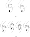
- the figure 1 schematically represents the possibilities of using a TNO according to the state of the art.
- the absence of penetration slots for the bristles on the rear face of the stationary head only allows the size of the bristles in the direction of penetration of the shaving head into the nasal opening in this case.
- the shaving head can not pick any hair by pulling out of the nasal opening, which reduces its effectiveness. This mode of use therefore favors the cut back hair is inefficient if the hair is inclined to the inside of the cavity.
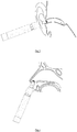
- the figure 2 schematically shows the possibilities of using a TNO according to the invention.
- the additional presence of penetration slots for the bristles on the rear face of the shaving head allows the size of the hairs both in the direction of penetration into the nasal opening and in the direction of withdrawal.
- the shaving head can also capture the hair by withdrawing from the nasal opening, straightening the hairs that go up in the cavity which increases its effectiveness.
- TNO according to the invention shaves both in the direction of the penetration in the direction of withdrawal of the orifice.
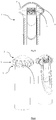
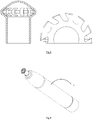
- the figure 5 represents a sectional view of an embodiment of the head of the TNO according to the invention.
- the figure 6 represents a three-dimensional view with a partial section showing the arrangement of the elements inside the head as well as the penetration slots present on both the front, side and rear faces of the head in the direction of the penetration .
- the head generally has a truncated bicon form.
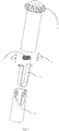
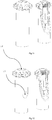
- the figure 7 represents an exploded view of the head of the TNO according to an embodiment of the invention with its constituent elements.
- the spring pushes the moving blades against the front and rear faces of the stationary blade.
- the figure 8 represents a front view and a plan view of the stationary blade of the TNO according to the invention.
- the figure 9 represents a 3D overview of an embodiment of the TNO according to the present invention with its handle that integrates a motor and a rechargeable battery or a battery.
- the handle can take different forms and its shape is limited only by practical considerations of grip.
- the figure 10 represents a non-limiting set of TNO shaving heads according to the present invention. All these heads have the characteristic of having on the stationary blade not only penetration slots on the front and side parts but also on the rear face of the head in the direction of penetration into the shaving orifice.
- the figure 11 represents another embodiment of the invention with an opening in the center of the stationary blade facilitating rinsing with water.
- the figure 12 the same mode of execution as that of the figure 11 but with an additional opening on the drive cylinder of the movable blade for the passage of the rinsing water.
- the origin of the present invention resides in the observation that the prior art nose-nosed trimmers (TNO) shaved nose and ear hairs only in the direction of the penetration of the shaving head into the orifices. concerned. This is simply due to the absence of slots for the penetration of the hairs into the stationary blade on all sides of the head.
- the penetration slots are generally located on the front side, that is to say the front face of the head in the direction of penetration into the cavity. mow, the slots usually overflow a little on the side faces as shown on the figure 1 .
- the present invention proposes a TNO with a shaving head having slots for the penetration of the bristles on all the faces of the stationary blade, therefore also on the rear face, which makes it possible to increase significantly shave efficiency and limit the number of back and forth movements for an identical result.
- the figure 10 represents a non-limiting set of TNO shaving heads corresponding to this main feature of the invention.
- the presence of slots for the penetration of the bristles on a large part of the front, side and rear faces also increases the accessibility of the rinsing water to the movable blade for cleaning the head.
- the slots for the penetration 7 of the bristles of the stationary blade 5 extend uninterruptedly between the front face 2 and the rear face 4 through the side face 3.
- the slots are not interrupted by a possible shift between the slots of the front 2, side 3 and rear 4 which allows them to function as a comb which is the desired effect.
- the movable blades 6 are pushed by a single spring 8 against the inner wall of the stationary blade 5, when it has a biconical shape.
- the stationary blades of the state of the art generally require two springs, a spring for the thrust in the direction of the axis of rotation and another for thrust in the perpendicular direction of the axis of rotation.
- the device according to the invention may be equipped with one or more luminescent electrodes for illuminating the orifices to be treated.
Description
La présente invention se rapporte à une tondeuse pour poils de nez et d'oreilles (TNO) ou « nose and ear trimmer » (NET) en anglais.The present invention relates to a trimmer for nose and ear hair (TNO) or "nose and ear trimmer" (NET) in English.
Les tondeuses de poils de nez et d'oreilles (TNO) sont désormais bien connues des utilisateurs confrontés aux problèmes des poils poussant dans les narines et les creux de l'oreille à partir de l'âge mûr.Ear and nose hair trimmers (TNO) are now well known to users who have problems with hair growing in the nostrils and troughs of the ear from middle age.
Différentes solutions ont été proposées pour aborder ce problème dont l'une des premières date de 1933 quand le brevet
Bien que les TNO ont connu de nombreuses évolutions depuis cette époque, le mécanisme de base est resté le même.Although the NWT has undergone many changes since then, the basic mechanism has remained the same.
Le document
Le document
Le document
D'autres améliorations ont également été proposées dans
Les perfectionnements de ces dernières années sont divulgués dans
Plus récemment encore,
Malgré les perfectionnements de ces dernières années, toutes les TNO de l'état de la technique, en dehors des tondeuses à lames latérales, ont généralement un dispositif de coupe mobile tournant au sein d'une tête stationnaire en forme de cylindre arrondi qui ne peut principalement couper les poils que sur la face avant dans le sens de pénétration des cavités où les poils se situent. Ce type de TNO ne coupe pratiquement rien dans le sens de sortie des cavités parce qu'une pénétration des poils dans les fentes de la tête stationnaire n'est prévue que sur la face avant principalement, et dans une moindre mesure sur les faces latérales.Despite the improvements of recent years, all TNOs of the state of the art, apart from the side-blade mowers, generally have a movable cutting device rotating within a rounded cylinder-shaped stationary head which can not mainly cut the hairs only on the front side in the direction of penetration of the cavities where the hairs lie. This type of TNO cuts practically nothing in the direction of exit of the cavities because a penetration of the hairs in the slots of the stationary head is provided only on the front face mainly, and to a lesser extent on the lateral faces.
La présente invention vise à fournir une TNO offrant la possibilité de tondre des poils aussi bien par la face avant de la tête de rasage dans le sens de la pénétration que par la face arrière de celle-ci lors du retrait des cavités nasales et auriculaires en proposant une tête stationnaire de géométrie particulière munie de fentes d'ouverture non seulement sur la partie arrondie frontale et/ou latérale du cylindre que nous appelons les faces avant et latérales dans le sens de la pénétration de la tête de rasage mais également sur la partie arrière de celle-ci.The present invention aims to provide a TNO offering the possibility of mowing the bristles both by the front face of the shaving head in the direction of penetration and by the rear face thereof during the removal of the nasal and auricular cavities. proposing a stationary head of particular geometry provided with opening slots not only on the rounded front and / or side of the cylinder which we call the front and side faces in the direction of penetration of the shaving head but also on the part back of it.
La présente invention divulgue une tondeuse motorisée pour les poils poussant dans les cavités du nez et des oreilles comportant une tête de rasage avec une lame mobile et une lame stationnaire, la lame stationnaire étant équipée de fentes pour la pénétration des poils sur la face avant et sur la face latérale vu dans le sens d'introduction de la tête de rasage dans la cavité à tondre, caractérisée en ce que ladite lame stationnaire comporte également des fentes pour la pénétration des poils sur sa face arrière permettant de couper également les poils lors du retrait de la tête de rasage de la cavité à tondre.The present invention discloses a motorized mower for the hairs growing in the cavities of the nose and ears comprising a shaving head with a movable blade and a stationary blade, the stationary blade being equipped with slots for the penetration of the bristles on the front face and on the lateral face seen in the direction of introduction of the shaving head into the cavity to be mowed, characterized in that said stationary blade also has slots for the penetration of the bristles on its rear face to also cut the bristles during the removal of the shaving head from the cavity to be mowed.
Les modes d'exécution préférés de l'invention comportent au moins une, ou une quelconque combinaison appropriée des caractéristiques suivantes :
- la tête stationnaire a globalement une forme de bicone tronqué ;
- la tête comporte un ressort unique poussant les lames mobiles contre les faces avant et arrière de ladite tête ;
- la lame stationnaire comporte une ouverture au centre de sa face avant ;
- la lame stationnaire comporte une ouverture au centre de sa face avant et le cylindre d'entrainement comporte une ouverture sur sa face latérale ;
- les fentes pour la pénétration des poils de la lame stationnaire forment un angle de coupe avec la direction radiale et par rapport à l'axe de rotation de ladite tête de rasage ;
- les fentes pour la pénétration des poils de la lame stationnaire se prolongent de manière ininterrompue entre la face avant et la face arrière en passant par la face latérale.
- the stationary head generally has a truncated bicone shape;
- the head comprises a single spring pushing the movable blades against the front and rear faces of said head;
- the stationary blade has an opening in the center of its front face;
- the stationary blade has an opening in the center of its front face and the drive cylinder has an opening on its side face;
- the slots for the penetration of the bristles of the stationary blade form a cutting angle with the radial direction and with respect to the axis of rotation of said shaving head;
- the slots for the penetration of the hairs of the stationary blade extend uninterruptedly between the front face and the rear face through the side face.
La
La
Les
La
La
La
La
La
La
La
La
- 1. Tête de rasage de la TNO1. TNO shaving head
- 2. Face avant de la tête de la TNO (partie frontale de la tête)2. Front face of the TNO head (front part of the head)
- 3. Face latérale de la tête de la TNO3. Side view of the head of the NWT
- 4. Face arrière de la tête de la TNO4. Back of the head of TNO
- 5. Lame stationnaire5. Stationary blade
- 6. Lame mobile6. Moving blade
- 7. Fentes pour la pénétration des poils7. Slits for hair penetration
- 8. Ressort8. Spring
- 9. Poignée9. Handle
- 10. Cylindre d'entraînement10. Drive cylinder
- 11. Dispositif de maintien des lames mobiles11. Device for holding moving blades
- 12. Ouverture sur la lame stationnaire12. Opening on the stationary blade
- 13. Ouverture sur le cylindre d'entraînement13. Opening on the drive cylinder
L'origine de la présente invention réside dans le constat que les tondeuses nez oreilles (TNO) de l'état de la technique ne rasent les poils du nez et des oreilles que dans le sens de la pénétration de la tête de rasage dans les orifices concernés. Ceci est tout simplement dû à l'absence de fentes pour la pénétration des poils dans la lame stationnaire sur tous les côtés de la tête. Sur les têtes de rasage des TNO de l'état de la technique, les fentes de pénétration sont généralement situées sur le côté frontal, c'est-à-dire la face avant de la tête dans le sens de la pénétration dans la cavité à tondre, les fentes débordent généralement un peu sur les faces latérales comme représenté sur la
Pour augmenter l'efficacité de rasage, la présente invention propose une TNO avec une tête de rasage présentant des fentes pour la pénétration des poils sur l'ensemble des faces de la lame stationnaire, donc également sur la face arrière ce qui permet d'augmenter considérablement l'efficacité de rasage et de limiter le nombre de mouvements de va-et-vient pour un résultat identique.To increase the shaving efficiency, the present invention proposes a TNO with a shaving head having slots for the penetration of the bristles on all the faces of the stationary blade, therefore also on the rear face, which makes it possible to increase significantly shave efficiency and limit the number of back and forth movements for an identical result.
La
De préférence, les fentes pour la pénétration 7 des poils de la lame stationnaire 5 se prolongent de manière ininterrompue entre la face avant 2 et la face arrière 4 en passant par la face latérale 3. Les fentes ne sont donc pas interrompues par un décalage éventuel entre les fentes des faces avant 2, latérales 3 et arrières 4 ce qui leur permet de fonctionner comme un peigne ce qui est l'effet recherché.Preferably, the slots for the
Pour améliorer encore la facilité de nettoyage de la tête, on peut prévoir une ouverture 12 sur le dôme de la partie centrale de la lame stationnaire 5 et même associer celle-ci à une ouverture supplémentaire sur le cylindre d'entraînement 13 pour assurer un flux d'eau à travers le dispositif lors du rinçage.To further improve the ease of cleaning of the head, it is possible to provide an
Les lames mobiles 6, sont poussées par un ressort 8 unique contre la paroi interne de la lame stationnaire 5, lorsque celle-ci a une forme biconique. Les lames stationnaires de l'état de la technique ont généralement besoin de deux ressorts, un ressort pour la poussée dans le sens de l'axe de rotation et un autre pour la poussée dans le sens perpendiculaire de l'axe de rotation.The
Pour éviter que les lames mobiles pénètrent dans les fentes pour la pénétration des poils de la lame stationnaire 5, celles-ci forment un angle de coupe avec la direction radiale de la tête de rasage ; pour l'amélioration de la coupe, elles forment également un angle par rapport à l'axe de rotation de ladite tête de rasage.To prevent the movable blades from entering the slots for the penetration of the bristles of the
Le dispositif selon l'invention peut être équipé d'une ou de plusieurs électrodes luminescentes pour éclairer les orifices à traiter.The device according to the invention may be equipped with one or more luminescent electrodes for illuminating the orifices to be treated.
Claims (7)
- A motorized trimmer for hairs growing in the nose and ear cavities, comprising a shaving head (1) with a movable blade (6) and a stationary blade (5), the stationary blade being equipped with slots for the penetration of hairs (7) on the front face (2) and on the side face (3) as viewed in the direction of introduction of the shaving head (1) into the cavity to be trimmed, characterized in that said stationary blade (5) also comprises slots for the penetration of hairs (7) on its rear face (4) also allowing cutting of hairs upon withdrawal of the shaving head (1) from the cavity to be trimmed.
- The trimmer according to claim 1, characterized in that the stationary head (5) globally has the form of a truncated bicone.
- The trimmer according to any one of the preceding claims, characterized in that said head (1) comprises a single spring (8) pushing the movable blades (6) against the front (2) and rear (4) faces of said head.
- The trimmer according to any one of the preceding claims, characterized in that the stationary blade (5) comprises an opening (12) at the center of its front face.
- The trimmer according to any one of the preceding claims, characterized in that the stationary blade (5) comprises an opening (12) at the center of its front face and the drive cylinder (11) comprises an opening (13) on its side face.
- The trimmer according to any one of the preceding claims, characterized in that the slots for the penetration (7) of hairs of the stationary blade (5) form a cutting angle with the radial direction and relative to the rotation axis of said shaving head (1).
- The trimmer according to any one of the preceding claims, characterized in that the slots for the penetration (7) of hairs of the stationary blade (5) extend uninterrupted between the front face (2) and the rear face (4), passing through the side face (3).
Applications Claiming Priority (2)
| Application Number | Priority Date | Filing Date | Title |
|---|---|---|---|
| EP14180988.9A EP2985124A1 (en) | 2014-08-14 | 2014-08-14 | Nose- and ear-hair trimmer |
| PCT/EP2015/066448 WO2016023706A1 (en) | 2014-08-14 | 2015-07-17 | Clippers for nose and ear hairs |
Publications (2)
| Publication Number | Publication Date |
|---|---|
| EP3142833A1 EP3142833A1 (en) | 2017-03-22 |
| EP3142833B1 true EP3142833B1 (en) | 2017-11-01 |
Family
ID=51357773
Family Applications (2)
| Application Number | Title | Priority Date | Filing Date |
|---|---|---|---|
| EP14180988.9A Withdrawn EP2985124A1 (en) | 2014-08-14 | 2014-08-14 | Nose- and ear-hair trimmer |
| EP15741154.7A Active EP3142833B1 (en) | 2014-08-14 | 2015-07-17 | Nose- and ear-hair trimmer |
Family Applications Before (1)
| Application Number | Title | Priority Date | Filing Date |
|---|---|---|---|
| EP14180988.9A Withdrawn EP2985124A1 (en) | 2014-08-14 | 2014-08-14 | Nose- and ear-hair trimmer |
Country Status (20)
| Country | Link |
|---|---|
| US (1) | US10335966B2 (en) |
| EP (2) | EP2985124A1 (en) |
| JP (2) | JP6629761B2 (en) |
| KR (1) | KR101806352B1 (en) |
| CN (1) | CN106573385B (en) |
| AU (1) | AU2015303427B2 (en) |
| BR (1) | BR212017000451Y1 (en) |
| CA (1) | CA2948963C (en) |
| CL (1) | CL2017000332A1 (en) |
| CR (1) | CR20170052A (en) |
| DK (1) | DK3142833T3 (en) |
| DO (1) | DOP2017000024A (en) |
| ES (1) | ES2655297T3 (en) |
| HK (1) | HK1231440A1 (en) |
| IL (1) | IL249808B (en) |
| MX (1) | MX2017001972A (en) |
| NZ (1) | NZ727666A (en) |
| RU (1) | RU2648716C1 (en) |
| SA (1) | SA517380895B1 (en) |
| WO (1) | WO2016023706A1 (en) |
Families Citing this family (6)
| Publication number | Priority date | Publication date | Assignee | Title |
|---|---|---|---|---|
| CN110650826B (en) | 2017-03-14 | 2022-06-03 | 巴克斯卡佩控股公司 | Back hair and body hair trimming devices and related methods of use |
| USD975921S1 (en) * | 2018-12-10 | 2023-01-17 | William Alexander Basztyk | Shaver handle |
| CA185156S (en) * | 2018-12-10 | 2021-01-20 | Basztyk William Alexander | Shaver handle |
| EP3753690A1 (en) * | 2019-06-21 | 2020-12-23 | Koninklijke Philips N.V. | Guard element for use in a hair-cutting unit |
| KR102325633B1 (en) * | 2021-01-13 | 2021-11-12 | 로얄금속공업 주식회사 | A rotary hair-cutting device |
| USD1021256S1 (en) | 2021-06-30 | 2024-04-02 | Conair Llc | Multifunction grooming appliance |
Family Cites Families (40)
| Publication number | Priority date | Publication date | Assignee | Title |
|---|---|---|---|---|
| US1973631A (en) | 1933-09-05 | 1934-09-11 | Max F Johnson | Hair clipper |
| US2212856A (en) * | 1938-03-23 | 1940-08-27 | American Safety Razor Corp | Clipping device |
| US2331873A (en) * | 1941-03-24 | 1943-10-19 | Thews Otto | Electric razor |
| US2987818A (en) | 1959-03-04 | 1961-06-13 | Juda L Rosenstein | Supplemental cutting attachment for electric razors |
| US3284894A (en) * | 1965-06-21 | 1966-11-15 | Joseph J Ryan | Razor having hair trimming means |
| US3731379A (en) | 1971-12-17 | 1973-05-08 | R Williams | Hair cutting apparatus |
| US3965569A (en) * | 1974-08-19 | 1976-06-29 | Bolduc Lee R | Cutting apparatus |
| US3925888A (en) | 1974-09-30 | 1975-12-16 | William G Bozsanyi | Hair clipper for the nose and ears |
| FR2430829A1 (en) | 1978-07-11 | 1980-02-08 | Gillet Max | Dry electric shaver for trimming e.g. nostril hair - has foil of rocket nose cone shape contg. revolving cutter and mounted on end of cased drive shaft |
| JPS5940889A (en) | 1982-08-31 | 1984-03-06 | 松下電工株式会社 | Blade of electric razor |
| US4521962A (en) * | 1984-02-27 | 1985-06-11 | Harold Van Natta | Grooming device |
| US4958432A (en) | 1989-10-26 | 1990-09-25 | Marshall Willie J | Rotary hair trimmer |
| IL93142A (en) * | 1990-01-23 | 1994-04-12 | Davidovitz Zvi | Electric fingernail clipper |
| US4980973A (en) * | 1990-02-28 | 1991-01-01 | Lee Chin Piao | Shaver having a clipper |
| US5979056A (en) | 1995-06-07 | 1999-11-09 | Andrews; Edward A. | Body shaving device with curved razor blade strip |
| US6505403B1 (en) | 1995-06-07 | 2003-01-14 | Edward A. Andrews | Hair shaving device with u-shaped razor blade strip |
| JPH09225158A (en) | 1996-02-26 | 1997-09-02 | Matsushita Electric Works Ltd | Nostril hair cutter |
| US6067714A (en) | 1997-10-03 | 2000-05-30 | Sharper Image Corporation | Turbo cleaning illuminated personal groomer |
| US6151785A (en) | 1998-05-14 | 2000-11-28 | Morris; Lionel | Pen-shaped hair clipper |
| US6272752B1 (en) | 1999-08-30 | 2001-08-14 | Robert F. Pino | Hair trimming tool |
| US6711822B1 (en) * | 2002-05-10 | 2004-03-30 | Mary K. Ginns | Single rotary blade grooming trimmer |
| US20040068873A1 (en) * | 2002-10-09 | 2004-04-15 | Thomas Tona | Rotary trimmer and shaving device |
| US6836965B1 (en) * | 2003-03-14 | 2005-01-04 | Alrita Ross | Rotational hair cutting device |
| US20050028369A1 (en) * | 2003-03-31 | 2005-02-10 | Nico Cocchiarella | Nostril hair trimmer with rotating cutter blade |
| US20050005453A1 (en) * | 2003-07-07 | 2005-01-13 | Zoltan Egeresi | Water pressure driven wet and dry shaver with beard trimmer, water clean out, and speed control |
| US20050198824A1 (en) * | 2004-03-12 | 2005-09-15 | White Dennis J. | Rotary hair trimmer |
| JP4526942B2 (en) | 2004-12-17 | 2010-08-18 | 株式会社 菊星 | Shaver |
| FR2887172B1 (en) * | 2005-06-20 | 2008-08-01 | 3D Clip Sarl | RAZOR TYPE APPARATUS, MOWER, EPILATOR AND / OR "EXFOLIATEUR", HAVING AT LEAST ONE REMOVABLE HEAD |
| JP2007029382A (en) | 2005-07-26 | 2007-02-08 | Matsushita Electric Works Ltd | Nose hair cutter |
| JP4186965B2 (en) | 2005-07-26 | 2008-11-26 | 松下電工株式会社 | Nose hair cutter |
| JP4203670B2 (en) | 2005-08-05 | 2009-01-07 | パナソニック電工株式会社 | Nose hair cutter |
| US20110010941A1 (en) | 2009-07-20 | 2011-01-20 | Specialife Industries Limited | Nose hair trimmer with dual cutting edges |
| US20110016722A1 (en) * | 2009-07-27 | 2011-01-27 | Dayton Stark | Razor system |
| JP5132645B2 (en) | 2009-09-18 | 2013-01-30 | パナソニック株式会社 | Nose hair cutter |
| JP2011062446A (en) * | 2009-09-18 | 2011-03-31 | Panasonic Electric Works Co Ltd | Nose hair trimmer |
| JP4971403B2 (en) * | 2009-09-25 | 2012-07-11 | パナソニック株式会社 | Hair removal machine |
| JP4894902B2 (en) | 2009-09-25 | 2012-03-14 | パナソニック電工株式会社 | Hair removal machine |
| JP5043974B2 (en) * | 2010-03-25 | 2012-10-10 | パナソニック株式会社 | Nose hair cutter |
| SE1230140A1 (en) | 2012-12-04 | 2014-06-05 | Roger Stenquist | Hair trimmer |
| US20150251325A1 (en) | 2014-03-04 | 2015-09-10 | Spectrum Brands, Inc. | Electric Hair Trimmer |
-
2014
- 2014-08-14 EP EP14180988.9A patent/EP2985124A1/en not_active Withdrawn
-
2015
- 2015-07-17 CN CN201580042535.8A patent/CN106573385B/en active Active
- 2015-07-17 AU AU2015303427A patent/AU2015303427B2/en active Active
- 2015-07-17 DK DK15741154.7T patent/DK3142833T3/en active
- 2015-07-17 CA CA2948963A patent/CA2948963C/en active Active
- 2015-07-17 US US15/503,921 patent/US10335966B2/en active Active - Reinstated
- 2015-07-17 ES ES15741154.7T patent/ES2655297T3/en active Active
- 2015-07-17 CR CR20170052A patent/CR20170052A/en unknown
- 2015-07-17 KR KR1020177006895A patent/KR101806352B1/en active IP Right Grant
- 2015-07-17 JP JP2016567826A patent/JP6629761B2/en active Active
- 2015-07-17 RU RU2016149204A patent/RU2648716C1/en active
- 2015-07-17 WO PCT/EP2015/066448 patent/WO2016023706A1/en active Application Filing
- 2015-07-17 EP EP15741154.7A patent/EP3142833B1/en active Active
- 2015-07-17 MX MX2017001972A patent/MX2017001972A/en unknown
- 2015-07-17 BR BR212017000451U patent/BR212017000451Y1/en active IP Right Grant
- 2015-07-17 NZ NZ727666A patent/NZ727666A/en unknown
-
2016
- 2016-12-27 IL IL249808A patent/IL249808B/en unknown
-
2017
- 2017-01-25 DO DO2017000024A patent/DOP2017000024A/en unknown
- 2017-02-09 CL CL2017000332A patent/CL2017000332A1/en unknown
- 2017-02-13 SA SA517380895A patent/SA517380895B1/en unknown
- 2017-05-24 HK HK17105262.1A patent/HK1231440A1/en unknown
-
2018
- 2018-04-12 JP JP2018076898A patent/JP6662941B2/en active Active
Non-Patent Citations (1)
| Title |
|---|
| None * |
Also Published As
| Publication number | Publication date |
|---|---|
| JP6662941B2 (en) | 2020-03-11 |
| CA2948963A1 (en) | 2016-02-18 |
| CL2017000332A1 (en) | 2017-08-18 |
| NZ727666A (en) | 2018-02-23 |
| JP2018161480A (en) | 2018-10-18 |
| MX2017001972A (en) | 2017-05-15 |
| AU2015303427B2 (en) | 2017-11-23 |
| KR20170038074A (en) | 2017-04-05 |
| HK1231440A1 (en) | 2017-12-22 |
| JP6629761B2 (en) | 2020-01-15 |
| CN106573385B (en) | 2018-04-13 |
| CN106573385A (en) | 2017-04-19 |
| EP2985124A1 (en) | 2016-02-17 |
| JP2017523818A (en) | 2017-08-24 |
| BR212017000451Y1 (en) | 2020-01-14 |
| EP3142833A1 (en) | 2017-03-22 |
| CR20170052A (en) | 2017-03-23 |
| US20170239825A1 (en) | 2017-08-24 |
| DK3142833T3 (en) | 2018-02-05 |
| IL249808B (en) | 2021-12-01 |
| AU2015303427A1 (en) | 2017-01-12 |
| ES2655297T3 (en) | 2018-02-19 |
| WO2016023706A1 (en) | 2016-02-18 |
| BR212017000451U2 (en) | 2018-02-14 |
| IL249808A0 (en) | 2017-03-30 |
| SA517380895B1 (en) | 2020-09-03 |
| DOP2017000024A (en) | 2017-04-16 |
| CA2948963C (en) | 2017-07-04 |
| US10335966B2 (en) | 2019-07-02 |
| RU2648716C1 (en) | 2018-03-28 |
| KR101806352B1 (en) | 2017-12-07 |
Similar Documents
| Publication | Publication Date | Title |
|---|---|---|
| EP3142833B1 (en) | Nose- and ear-hair trimmer | |
| EP3377281B1 (en) | Hair clipper with collector | |
| EP2894959B1 (en) | Rotary cutting head with wires and assembly consisting of such a head and a drive shaft for driving said head | |
| EP2380424B1 (en) | Rotary cutting head using flexible filiform cutting elements and cutting devices provided with such a cutting head. | |
| EP3302902B1 (en) | Beard trimmer with one or more rotating heads surrounded by combs with particular geometry and equipped with a protection position for the comb | |
| FR2462974A1 (en) | SHAVING BLOCK FOR ELECTRIC RAZOR WITH ROTATING HEAD | |
| FR2946492A3 (en) | TRIMMER | |
| EP3302901B1 (en) | Beard trimmer with one or more rotating heads having a fixed blade with particular geometry | |
| EP1903855B1 (en) | Device for pruning and shredding plants | |
| EP3237154B1 (en) | Beard clipper with one or more rotating heads | |
| FR2888085A1 (en) | CUTTING HEAD FOR A BRUSHCUTTER | |
| FR2651089A1 (en) | Improvements made to portable treedozer heads | |
| EP0603086B1 (en) | Blade for machines like portable brush cutters and lawn mowers | |
| EP3302903A1 (en) | Beard trimmer comprising one or more rotating heads having a cleaning arrangement | |
| CA2970354C (en) | Mowing or grinding device | |
| EP1701607B1 (en) | Cutting head for bush cutter, hedge cutter or the like provided with improved means for locking a cutting wire | |
| EP0266674B1 (en) | Hairdressers' scissors | |
| FR2469987A1 (en) | SHAVER | |
| CA1062576A (en) | Harvested root plants, such as beets, topping apparatus | |
| FR2737078A1 (en) | Portable hydraulic pruner, e.g. for pruning in forests, fruit pruning, etc. - consists of hydraulic unit, supplying pressurised fluid to cutting head with double acting jack to drive lower cutter against fixed counter blade | |
| EP3272210A1 (en) | Rotor for clearing apparatus | |
| FR3032597A1 (en) | LAMIER DEVICE, AND MODULE FOR LAMIER DEVICE | |
| FR3032141A1 (en) | MECHANICAL BARBER MOWER | |
| FR3046371A3 (en) | BLADE INTENDED TO BE REMOVABLY MOUNTED BETWEEN TWO COMBINES OF A MOWER OR RAZOR |
Legal Events
| Date | Code | Title | Description |
|---|---|---|---|
| PUAI | Public reference made under article 153(3) epc to a published international application that has entered the european phase |
Free format text: ORIGINAL CODE: 0009012 |
|
| 17P | Request for examination filed |
Effective date: 20161216 |
|
| AK | Designated contracting states |
Kind code of ref document: A1 Designated state(s): AL AT BE BG CH CY CZ DE DK EE ES FI FR GB GR HR HU IE IS IT LI LT LU LV MC MK MT NL NO PL PT RO RS SE SI SK SM TR |
|
| AX | Request for extension of the european patent |
Extension state: BA ME |
|
| GRAP | Despatch of communication of intention to grant a patent |
Free format text: ORIGINAL CODE: EPIDOSNIGR1 |
|
| DAV | Request for validation of the european patent (deleted) | ||
| DAX | Request for extension of the european patent (deleted) | ||
| INTG | Intention to grant announced |
Effective date: 20170524 |
|
| RIN1 | Information on inventor provided before grant (corrected) |
Inventor name: JULEMONT, PIERRE |
|
| GRAS | Grant fee paid |
Free format text: ORIGINAL CODE: EPIDOSNIGR3 |
|
| GRAA | (expected) grant |
Free format text: ORIGINAL CODE: 0009210 |
|
| AK | Designated contracting states |
Kind code of ref document: B1 Designated state(s): AL AT BE BG CH CY CZ DE DK EE ES FI FR GB GR HR HU IE IS IT LI LT LU LV MC MK MT NL NO PL PT RO RS SE SI SK SM TR |
|
| REG | Reference to a national code |
Ref country code: GB Ref legal event code: FG4D Free format text: NOT ENGLISH |
|
| REG | Reference to a national code |
Ref country code: CH Ref legal event code: EP Ref country code: AT Ref legal event code: REF Ref document number: 941602 Country of ref document: AT Kind code of ref document: T Effective date: 20171115 |
|
| REG | Reference to a national code |
Ref country code: IE Ref legal event code: FG4D Free format text: LANGUAGE OF EP DOCUMENT: FRENCH |
|
| REG | Reference to a national code |
Ref country code: DE Ref legal event code: R096 Ref document number: 602015005750 Country of ref document: DE |
|
| REG | Reference to a national code |
Ref country code: DK Ref legal event code: T3 Effective date: 20180131 |
|
| REG | Reference to a national code |
Ref country code: ES Ref legal event code: FG2A Ref document number: 2655297 Country of ref document: ES Kind code of ref document: T3 Effective date: 20180219 |
|
| REG | Reference to a national code |
Ref country code: NL Ref legal event code: MP Effective date: 20171101 |
|
| REG | Reference to a national code |
Ref country code: LT Ref legal event code: MG4D |
|
| REG | Reference to a national code |
Ref country code: AT Ref legal event code: MK05 Ref document number: 941602 Country of ref document: AT Kind code of ref document: T Effective date: 20171101 |
|
| PG25 | Lapsed in a contracting state [announced via postgrant information from national office to epo] |
Ref country code: SE Free format text: LAPSE BECAUSE OF FAILURE TO SUBMIT A TRANSLATION OF THE DESCRIPTION OR TO PAY THE FEE WITHIN THE PRESCRIBED TIME-LIMIT Effective date: 20171101 Ref country code: NO Free format text: LAPSE BECAUSE OF FAILURE TO SUBMIT A TRANSLATION OF THE DESCRIPTION OR TO PAY THE FEE WITHIN THE PRESCRIBED TIME-LIMIT Effective date: 20180201 Ref country code: FI Free format text: LAPSE BECAUSE OF FAILURE TO SUBMIT A TRANSLATION OF THE DESCRIPTION OR TO PAY THE FEE WITHIN THE PRESCRIBED TIME-LIMIT Effective date: 20171101 Ref country code: LT Free format text: LAPSE BECAUSE OF FAILURE TO SUBMIT A TRANSLATION OF THE DESCRIPTION OR TO PAY THE FEE WITHIN THE PRESCRIBED TIME-LIMIT Effective date: 20171101 Ref country code: NL Free format text: LAPSE BECAUSE OF FAILURE TO SUBMIT A TRANSLATION OF THE DESCRIPTION OR TO PAY THE FEE WITHIN THE PRESCRIBED TIME-LIMIT Effective date: 20171101 |
|
| PG25 | Lapsed in a contracting state [announced via postgrant information from national office to epo] |
Ref country code: LV Free format text: LAPSE BECAUSE OF FAILURE TO SUBMIT A TRANSLATION OF THE DESCRIPTION OR TO PAY THE FEE WITHIN THE PRESCRIBED TIME-LIMIT Effective date: 20171101 Ref country code: BG Free format text: LAPSE BECAUSE OF FAILURE TO SUBMIT A TRANSLATION OF THE DESCRIPTION OR TO PAY THE FEE WITHIN THE PRESCRIBED TIME-LIMIT Effective date: 20180201 Ref country code: IS Free format text: LAPSE BECAUSE OF FAILURE TO SUBMIT A TRANSLATION OF THE DESCRIPTION OR TO PAY THE FEE WITHIN THE PRESCRIBED TIME-LIMIT Effective date: 20180301 Ref country code: HR Free format text: LAPSE BECAUSE OF FAILURE TO SUBMIT A TRANSLATION OF THE DESCRIPTION OR TO PAY THE FEE WITHIN THE PRESCRIBED TIME-LIMIT Effective date: 20171101 Ref country code: GR Free format text: LAPSE BECAUSE OF FAILURE TO SUBMIT A TRANSLATION OF THE DESCRIPTION OR TO PAY THE FEE WITHIN THE PRESCRIBED TIME-LIMIT Effective date: 20180202 Ref country code: RS Free format text: LAPSE BECAUSE OF FAILURE TO SUBMIT A TRANSLATION OF THE DESCRIPTION OR TO PAY THE FEE WITHIN THE PRESCRIBED TIME-LIMIT Effective date: 20171101 Ref country code: AT Free format text: LAPSE BECAUSE OF FAILURE TO SUBMIT A TRANSLATION OF THE DESCRIPTION OR TO PAY THE FEE WITHIN THE PRESCRIBED TIME-LIMIT Effective date: 20171101 |
|
| REG | Reference to a national code |
Ref country code: FR Ref legal event code: PLFP Year of fee payment: 4 |
|
| PG25 | Lapsed in a contracting state [announced via postgrant information from national office to epo] |
Ref country code: CY Free format text: LAPSE BECAUSE OF FAILURE TO SUBMIT A TRANSLATION OF THE DESCRIPTION OR TO PAY THE FEE WITHIN THE PRESCRIBED TIME-LIMIT Effective date: 20171101 Ref country code: EE Free format text: LAPSE BECAUSE OF FAILURE TO SUBMIT A TRANSLATION OF THE DESCRIPTION OR TO PAY THE FEE WITHIN THE PRESCRIBED TIME-LIMIT Effective date: 20171101 Ref country code: CZ Free format text: LAPSE BECAUSE OF FAILURE TO SUBMIT A TRANSLATION OF THE DESCRIPTION OR TO PAY THE FEE WITHIN THE PRESCRIBED TIME-LIMIT Effective date: 20171101 Ref country code: SK Free format text: LAPSE BECAUSE OF FAILURE TO SUBMIT A TRANSLATION OF THE DESCRIPTION OR TO PAY THE FEE WITHIN THE PRESCRIBED TIME-LIMIT Effective date: 20171101 |
|
| REG | Reference to a national code |
Ref country code: DE Ref legal event code: R097 Ref document number: 602015005750 Country of ref document: DE |
|
| PG25 | Lapsed in a contracting state [announced via postgrant information from national office to epo] |
Ref country code: PL Free format text: LAPSE BECAUSE OF FAILURE TO SUBMIT A TRANSLATION OF THE DESCRIPTION OR TO PAY THE FEE WITHIN THE PRESCRIBED TIME-LIMIT Effective date: 20171101 Ref country code: SM Free format text: LAPSE BECAUSE OF FAILURE TO SUBMIT A TRANSLATION OF THE DESCRIPTION OR TO PAY THE FEE WITHIN THE PRESCRIBED TIME-LIMIT Effective date: 20171101 |
|
| PLBE | No opposition filed within time limit |
Free format text: ORIGINAL CODE: 0009261 |
|
| STAA | Information on the status of an ep patent application or granted ep patent |
Free format text: STATUS: NO OPPOSITION FILED WITHIN TIME LIMIT |
|
| PG25 | Lapsed in a contracting state [announced via postgrant information from national office to epo] |
Ref country code: MT Free format text: LAPSE BECAUSE OF FAILURE TO SUBMIT A TRANSLATION OF THE DESCRIPTION OR TO PAY THE FEE WITHIN THE PRESCRIBED TIME-LIMIT Effective date: 20171101 |
|
| 26N | No opposition filed |
Effective date: 20180802 |
|
| REG | Reference to a national code |
Ref country code: CH Ref legal event code: PL |
|
| PG25 | Lapsed in a contracting state [announced via postgrant information from national office to epo] |
Ref country code: LU Free format text: LAPSE BECAUSE OF NON-PAYMENT OF DUE FEES Effective date: 20180717 Ref country code: MC Free format text: LAPSE BECAUSE OF FAILURE TO SUBMIT A TRANSLATION OF THE DESCRIPTION OR TO PAY THE FEE WITHIN THE PRESCRIBED TIME-LIMIT Effective date: 20171101 |
|
| REG | Reference to a national code |
Ref country code: IE Ref legal event code: MM4A |
|
| PG25 | Lapsed in a contracting state [announced via postgrant information from national office to epo] |
Ref country code: IE Free format text: LAPSE BECAUSE OF NON-PAYMENT OF DUE FEES Effective date: 20180717 Ref country code: CH Free format text: LAPSE BECAUSE OF NON-PAYMENT OF DUE FEES Effective date: 20180731 Ref country code: LI Free format text: LAPSE BECAUSE OF NON-PAYMENT OF DUE FEES Effective date: 20180731 |
|
| PG25 | Lapsed in a contracting state [announced via postgrant information from national office to epo] |
Ref country code: PT Free format text: LAPSE BECAUSE OF FAILURE TO SUBMIT A TRANSLATION OF THE DESCRIPTION OR TO PAY THE FEE WITHIN THE PRESCRIBED TIME-LIMIT Effective date: 20171101 |
|
| PG25 | Lapsed in a contracting state [announced via postgrant information from national office to epo] |
Ref country code: RO Free format text: LAPSE BECAUSE OF FAILURE TO SUBMIT A TRANSLATION OF THE DESCRIPTION OR TO PAY THE FEE WITHIN THE PRESCRIBED TIME-LIMIT Effective date: 20171101 Ref country code: MK Free format text: LAPSE BECAUSE OF NON-PAYMENT OF DUE FEES Effective date: 20171101 Ref country code: HU Free format text: LAPSE BECAUSE OF FAILURE TO SUBMIT A TRANSLATION OF THE DESCRIPTION OR TO PAY THE FEE WITHIN THE PRESCRIBED TIME-LIMIT; INVALID AB INITIO Effective date: 20150717 |
|
| PG25 | Lapsed in a contracting state [announced via postgrant information from national office to epo] |
Ref country code: AL Free format text: LAPSE BECAUSE OF FAILURE TO SUBMIT A TRANSLATION OF THE DESCRIPTION OR TO PAY THE FEE WITHIN THE PRESCRIBED TIME-LIMIT Effective date: 20171101 |
|
| PGFP | Annual fee paid to national office [announced via postgrant information from national office to epo] |
Ref country code: DK Payment date: 20200625 Year of fee payment: 6 Ref country code: TR Payment date: 20200625 Year of fee payment: 6 |
|
| PGFP | Annual fee paid to national office [announced via postgrant information from national office to epo] |
Ref country code: BE Payment date: 20200624 Year of fee payment: 6 |
|
| PG25 | Lapsed in a contracting state [announced via postgrant information from national office to epo] |
Ref country code: SI Free format text: LAPSE BECAUSE OF NON-PAYMENT OF DUE FEES Effective date: 20180717 |
|
| PGFP | Annual fee paid to national office [announced via postgrant information from national office to epo] |
Ref country code: IT Payment date: 20200622 Year of fee payment: 6 |
|
| REG | Reference to a national code |
Ref country code: DK Ref legal event code: EBP Effective date: 20210731 |
|
| REG | Reference to a national code |
Ref country code: BE Ref legal event code: MM Effective date: 20210731 |
|
| PG25 | Lapsed in a contracting state [announced via postgrant information from national office to epo] |
Ref country code: TR Free format text: LAPSE BECAUSE OF NON-PAYMENT OF DUE FEES Effective date: 20210717 |
|
| PG25 | Lapsed in a contracting state [announced via postgrant information from national office to epo] |
Ref country code: IT Free format text: LAPSE BECAUSE OF NON-PAYMENT OF DUE FEES Effective date: 20210717 Ref country code: DK Free format text: LAPSE BECAUSE OF NON-PAYMENT OF DUE FEES Effective date: 20210731 Ref country code: BE Free format text: LAPSE BECAUSE OF NON-PAYMENT OF DUE FEES Effective date: 20210731 |
|
| P01 | Opt-out of the competence of the unified patent court (upc) registered |
Effective date: 20230419 |
|
| PGFP | Annual fee paid to national office [announced via postgrant information from national office to epo] |
Ref country code: GB Payment date: 20230620 Year of fee payment: 9 Ref country code: ES Payment date: 20230801 Year of fee payment: 9 |
|
| PGFP | Annual fee paid to national office [announced via postgrant information from national office to epo] |
Ref country code: FR Payment date: 20230724 Year of fee payment: 9 Ref country code: DE Payment date: 20230620 Year of fee payment: 9 |