EP1903855B1 - Device for pruning and shredding plants - Google Patents
Device for pruning and shredding plants Download PDFInfo
- Publication number
- EP1903855B1 EP1903855B1 EP06779038A EP06779038A EP1903855B1 EP 1903855 B1 EP1903855 B1 EP 1903855B1 EP 06779038 A EP06779038 A EP 06779038A EP 06779038 A EP06779038 A EP 06779038A EP 1903855 B1 EP1903855 B1 EP 1903855B1
- Authority
- EP
- European Patent Office
- Prior art keywords
- pruning
- rotors
- shredding
- blades
- plants
- Prior art date
- Legal status (The legal status is an assumption and is not a legal conclusion. Google has not performed a legal analysis and makes no representation as to the accuracy of the status listed.)
- Not-in-force
Links
Images


Classifications
-
- A—HUMAN NECESSITIES
- A01—AGRICULTURE; FORESTRY; ANIMAL HUSBANDRY; HUNTING; TRAPPING; FISHING
- A01G—HORTICULTURE; CULTIVATION OF VEGETABLES, FLOWERS, RICE, FRUIT, VINES, HOPS OR SEAWEED; FORESTRY; WATERING
- A01G23/00—Forestry
- A01G23/02—Transplanting, uprooting, felling or delimbing trees
- A01G23/08—Felling trees
- A01G23/093—Combinations of shearing, sawing or milling apparatus specially adapted for felling trees
Definitions
- the present invention relates to a device for pruning and grinding vegetation.
- Pruning operations are generally carried out by means of chainsaws or the like, carried manually or mounted on tractors, while grinding is subsequently carried out by means of vegetable crushers.
- Pruning is a slow operation, and when it comes to treating tall hedges or trees along traffic lanes, it can lead to slowdowns.
- the present invention aims to overcome these various disadvantages by providing a device for pruning and grinding vegetation, allowing not only to perform both operations simultaneously, but also to achieve a rate never before reached .
- the device for pruning and grinding the vegetation comprises a grinding head disposed at the end of a steerable arm itself carried by a tractor capable of moving along the vegetation to be treated, said head comprises a casing comprising two parallel flanges between which are mounted two juxtaposed rotors parallel axes, equipped with radial knives and adapted to be rotated in opposite directions, so that the knives of said rotors move in the space between said rotors and cause the vegetation to cut and grind.
- one of the two flanges is largely indented.
- one of the flanges is extended by a deflector adapted to contain and guide said vegetation towards the rotors.
- the rotors each comprise a body in the form of a cylinder of relatively large diameter from which the knives protrude.
- At least one of the rotors is associated with counter-knives arranged at a flange at the entrance to the space separating said rotors.
- the pruning and grinding device comprises counter-knives arranged in line with the space which separates the rotors, and which each have an active edge, which preferably coincides with to the axis passing through the two axes rotors, so as to be parallel to the knives 15 when they cross said knives against.
- the pruning and grinding device comprises a scraper disposed at the space of the space separating the rotors, designed to pivot about an axis parallel to those of the rotors, so as to be able to take several positions between two extreme positions which correspond for one to the scraping of one rotor and the other to the scraping of the other rotor.
- scraper means integral with the housing, which is in the form of combs between the teeth from which the knives pass.
- the casing internally comprises means capable of slowing the progression of the plant material after its passage in the space between the rotors.
- the casing comprises openings positioned facing each of the rotors and intended for the discharge of the ground material, said openings being provided with deflector means capable of directing the mash flow.
- the steerable arm is adapted to be secured to a tractor, and it is at least two, preferably at least three degrees of freedom, so as to allow the grinding head to be placed in different orientations and at different heights.
- a device for pruning and grinding the vegetation comprises a head 1 mounted at the end of an articulated arm 2, visible on the figure 2 .
- the head 1 comprises a housing 10 comprising two flanges 11 and 12 which enclose and hold two rotors 13 and 14 of parallel axes which each comprise a cylinder body provided with radial knives 15, shown schematically, and separated by a space 16 in which evolve the knives 15.
- the two rotors 13 and 14 are rotated in the direction of arrows respectively F and R, so as to cause vegetation in the space 16, and to propel it into the housing 10 in order to realize the grinding.
- the knives 15 are preferably evenly distributed over the entire surface of the bodies of the rotors 13 and 14 so as not to favor the stuffing phenomena.
- the casing 10 is internally equipped with means 10 'able to slow the progression of the plant material, so as to increase the duration of its presence in the knife action zone 15 .
- These means may for example consist of bars protruding from the inner face of the housing 10 parallel to the axes of the rotors 13 and 14, and extending between the two flanges 11 and 12.
- the head 1 also comprises scraper elements 17 integral with the housing 1, and which extend between the knives 15 to come into substantially contact with the bodies of the rotors 13 and 14.
- the head 1 has at each of its ends, that is to say on either side of the rotors 13 and 14, an opening 18 for the discharge of the ground material.
- the head 1 means for collecting and discharging the ground material.
- the articulated arm. 2 which in this case is secured to the flange 12, moves the head 1 relative to the vegetation, and in particular so that the flange 11 remains substantially parallel to the direction of movement and vegetation.
- the articulated arm 2 has several degrees of freedom, at least two, preferably three.
- the flange 11 is widely indented to allow increased penetration into the vegetation, unlike the flange 12 thus containing the projections.
- counter-knives 3 shown schematically on the figure 1 , intended to facilitate the cutting of vegetation.
- These counter-knives 3 may consist of an extension of the flange 11 in the region of the space 16, and having, for each of the rotors 13 and 14, a toothed edge concentric to the rotor concerned, and of radius between that of the body of the rotor and knives 15.
- the head 1 is also provided, optionally, against knives 30, visible on the figure 1 disposed at the right of the space 16, and each having an active edge 31, which preferably coincides with the axis passing through the two axes of the rotors 13 and 14, so as to be parallel to the knives 15 when these cross the counter knives 30.
- the flange 12 is extended forward, that is to say on the side of which the knives 15 emerge, by a deflector 19 adapted to contain and guide the vegetation.
- the articulated arm 2 comprises mainly a movable arm 20 in pendular motion and secured to the head 1 opposite the rotor 14, and a jack 21 whose end is secured to the head 1 opposite the rotor 13, and which is intended, as it is lengthened or shortened, to vary the inclination of the head 1.
- the arm 20 is doubled by a drive shaft 22 which transmits the movement to the rotor 14, while a transmission shaft 23 allows the rotor 13 to be driven.
- the openings 18, not visible, for the discharge of the ground material are close to the middle region of the housing, and each open to the right of a flap 18 ', which is rotatable along an axis perpendicular to those of the rotors 13 and 14. It is therefore possible, by the pivoting flaps 18 ', to direct the flow of ground material.
- flaps can be replaced by chutes, also steerable, each of which covers an opening 18, thereby channeling the flow of ground material.
- the head 1 further comprises a scraper 4, disposed at the right of the space 16, and which acts between the counter knives 18 ', this scraper 4 being provided pivotally movable along an axis parallel to those of the rotors 13 and 14, so as to take two extreme positions which correspond for one to the scraping of the rotor 13 and the other to the scraping of the rotor 14.
- this scraper 4 also has a deflector function, since according to the extreme position chosen, the vegetation is directed towards one or the other of the rotors 13 and 14. On the other hand, by positioning the scraper 4 between the two positions extreme, the vegetation is directed simultaneously to the two rotors 13 and 14.
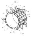
- a rotor 13 or 14 can be seen, which consists of a drum 5 externally provided with pairs 50 of crowns 51, intended to secure knife holders 52. Crowns 51 are pierced with holes 53 and have notches 54, while that the knife holders 52 each comprise firstly two pins 55, one at each end, and secondly holes, not visible.
- Each knife holder 52 is inserted between two rings 51 of a pair 50, the pins 55 are engaged in the notches 54 and are intended to support the shearing forces, the joining being carried out by means of bolts 56.
- notches 54 are of symmetrical shape, so as to allow the attachment of the knife holders 52 in one direction or the other.
- the knife holders 52 are each provided with a blade 57 which has a bevel 58.
- the bevels 58 are oriented towards the inside of the rotor, so as to maintain the vegetation and thus ensure optimum grinding.
- the embodiment which has just been described comprises a pair of rotors, while it is perfectly possible that it comprises several pairs.
- the two rotors shown are of identical dimensions, whereas according to the use for which the device is intended, the two rotors may be of different diameters in order to favor, on the side of the largest rotor, a direction of rotation. propulsion of plant matter.
Landscapes
- Life Sciences & Earth Sciences (AREA)
- Biodiversity & Conservation Biology (AREA)
- Ecology (AREA)
- Forests & Forestry (AREA)
- Environmental Sciences (AREA)
- Harvester Elements (AREA)
- Soil Working Implements (AREA)
- Shovels (AREA)
- Finish Polishing, Edge Sharpening, And Grinding By Specific Grinding Devices (AREA)
Description
La présente invention a pour objet un dispositif d'élagage et de broyage de la végétation.The present invention relates to a device for pruning and grinding vegetation.
L'entretien des abords des routes et chemins forestiers ou autres, nécessite de régulières opérations d'élagage, qui elles-mêmes génèrent des opérations de broyage de la végétation pour permettre l'enlèvement et le transport des déchets obtenus.The maintenance of the approaches to roads and forest or other roads requires regular pruning operations, which themselves generate operations of grinding vegetation to allow the removal and transport of waste obtained.
Les opérations d'élagages sont de manière générale réalisées au moyen de scies tronçonneuses ou analogues, portées manuellement ou montées sur des engins tracteurs, tandis que le broyage intervient ultérieurement au moyen de broyeurs à végétaux.Pruning operations are generally carried out by means of chainsaws or the like, carried manually or mounted on tractors, while grinding is subsequently carried out by means of vegetable crushers.
On utilise également des outils de coupe manuels traditionnels, ou bien des débroussailleuses, lesquelles sont toutefois inefficaces dès que les branches dépassent une certaine section.Traditional manual cutting tools or brushcutters are also used, but they are ineffective as soon as the branches exceed a certain section.
L'élagage est une opération lente, et lorsqu'il s'agit de traiter des haies hautes ou des arbres en bordure de voies de circulation, cela peut entraîner des ralentissements de la circulation.Pruning is a slow operation, and when it comes to treating tall hedges or trees along traffic lanes, it can lead to slowdowns.
En outre, le broyage étant une opération indépendante de celle de l'élagage, cela accroît les inconvénients précités.In addition, the grinding being an operation independent of that of pruning, this increases the aforementioned drawbacks.
La présente invention a pour but de remédier à ces divers inconvénients en proposant un dispositif d'élagage et de broyage de la végétation, permettant non seulement de réaliser ces deux opérations simultanément, mais également de les réaliser à une cadence encore jamais atteinte à ce jour.The present invention aims to overcome these various disadvantages by providing a device for pruning and grinding vegetation, allowing not only to perform both operations simultaneously, but also to achieve a rate never before reached .
Le document
Le dispositif d'élagage et de broyage de la végétation selon l'invention comporte une tête de broyage disposée à l'extrémité d'un bras orientable lui-même porté par un engin tracteur apte à se déplacer le long de la végétation à traiter, ladite tête comporte un carter comprenant deux flasques parallèles entre lesquels sont montés deux rotors juxtaposés d'axes parallèles, équipés de couteaux radiaux et aptes à être entraînés en rotation dans des sens inverses, en sorte que les couteaux desdits rotors évoluent dans l'espace qui sépare lesdits rotors et y entraînent la végétation en vue de la couper et de la broyer.The device for pruning and grinding the vegetation according to the invention comprises a grinding head disposed at the end of a steerable arm itself carried by a tractor capable of moving along the vegetation to be treated, said head comprises a casing comprising two parallel flanges between which are mounted two juxtaposed rotors parallel axes, equipped with radial knives and adapted to be rotated in opposite directions, so that the knives of said rotors move in the space between said rotors and cause the vegetation to cut and grind.
Selon une caractéristique additionnelle du dispositif d'élagage et de broyage selon l'invention, l'un des deux flasques, celui destiné à être placé au plus près de la végétation, est largement échancré.According to an additional feature of the pruning and grinding device according to the invention, one of the two flanges, the one intended to be placed closer to the vegetation, is largely indented.
Selon une autre caractéristique additionnelle du dispositif d'élagage et de broyage selon l'invention, l'un des flasques, celui destiné à être placé le plus loin de la végétation, est prolongé d'un déflecteur apte à contenir et guider ladite végétation vers les rotors.According to another additional feature of the pruning and grinding device according to the invention, one of the flanges, the one intended to be placed farthest from the vegetation, is extended by a deflector adapted to contain and guide said vegetation towards the rotors.
Selon une autre caractéristique additionnelle du dispositif d'élagage et de broyage selon l'invention, les rotors comprennent chacun un corps se présentant sous la forme d'un cylindre de relativement grand diamètre duquel font saillie les couteaux.According to another additional characteristic of the pruning and grinding device according to the invention, the rotors each comprise a body in the form of a cylinder of relatively large diameter from which the knives protrude.
Selon une autre caractéristique additionnelle du dispositif d'élagage et de broyage selon l'invention, au moins l'un des rotors est associé à des contre-couteaux disposés au niveau d'un flasque à l'entrée de l'espace qui sépare lesdits rotors.According to another additional feature of the pruning and grinding device according to the invention, at least one of the rotors is associated with counter-knives arranged at a flange at the entrance to the space separating said rotors.
Selon une autre caractéristique additionnelle du dispositif d'élagage et de broyage selon l'invention, il comporte des contre-couteaux disposés au droit de l'espace qui sépare les rotors, et qui présentent chacun un bord actif, qui de préférence est confondu avec à l'axe passant par les deux axes des rotors, en sorte d'être parallèle aux couteaux 15 lorsque ceux-ci croisent lesdits contre couteaux.According to another additional feature of the pruning and grinding device according to the invention, it comprises counter-knives arranged in line with the space which separates the rotors, and which each have an active edge, which preferably coincides with to the axis passing through the two axes rotors, so as to be parallel to the
Selon une autre caractéristique additionnelle du dispositif d'élagage et de broyage selon l'invention, il comporte un racleur disposé au droit de l'espace qui sépare les rotors, prévu mobile en pivotement selon un axe parallèle à ceux des rotors, en sorte de pouvoir prendre plusieurs positions entre deux positions extrêmes qui correspondent pour l'une au raclement d'un rotor et pour l'autre au raclement de l'autre rotor.According to another additional feature of the pruning and grinding device according to the invention, it comprises a scraper disposed at the space of the space separating the rotors, designed to pivot about an axis parallel to those of the rotors, so as to be able to take several positions between two extreme positions which correspond for one to the scraping of one rotor and the other to the scraping of the other rotor.
Selon une autre caractéristique additionnelle du dispositif d'élagage et de broyage selon l'invention, il est muni de moyens racleurs solidaires du carter, se présentant sous la forme de peignes entre les dents desquels passent les couteaux.According to another additional feature of the pruning and grinding device according to the invention, it is provided with scraper means integral with the housing, which is in the form of combs between the teeth from which the knives pass.
Selon une autre caractéristique additionnelle du dispositif d'élagage et de broyage selon l'invention, le carter comporte intérieurement des moyens aptes à ralentir la progression de la matière végétale après son passage dans l'espace qui sépare les rotors.According to another additional feature of the pruning and grinding device according to the invention, the casing internally comprises means capable of slowing the progression of the plant material after its passage in the space between the rotors.
Selon une autre caractéristique additionnelle du dispositif d'élagage et de broyage selon l'invention, le carter comporte des ouvertures positionnées en regard de chacun des rotors et destinées à l'évacuation du broyat, lesdites ouvertures étant équipées de moyens déflecteurs aptes à diriger le flux de broyat.According to another additional feature of the pruning and grinding device according to the invention, the casing comprises openings positioned facing each of the rotors and intended for the discharge of the ground material, said openings being provided with deflector means capable of directing the mash flow.
Selon une autre caractéristique additionnelle du dispositif d'élagage et de broyage selon l'invention, le bras orientable est prévu apte à être solidarisé à un engin tracteur, et il est à au moins deux, de préférence au moins trois, degrés de liberté, en sorte de permettre de placer la tête de broyage selon différentes orientations et à différentes hauteurs.According to another additional feature of the pruning and grinding device according to the invention, the steerable arm is adapted to be secured to a tractor, and it is at least two, preferably at least three degrees of freedom, so as to allow the grinding head to be placed in different orientations and at different heights.
Les avantages et les caractéristiques du dispositif d'élagage et de broyage selon l'invention, ressortiront plus clairement de la description qui suit et qui se rapporte au dessin annexé, lequel en représente un mode de réalisation non limitatif.The advantages and characteristics of the pruning and grinding device according to the invention will emerge more clearly from the description which follows and which refers to the appended drawing, which represents a non-limiting embodiment thereof.
Dans le dessin annexé :
- la
figure 1 représente une vue schématique de côté d'une partie du dispositif d'élagage et de broyage de la végétation selon l'invention. - la
figure 2 représente une vue schématique sous un autre angle du même dispositif. - la
figure 3 représente une vue schématique en perspective du même dispositif. - la
figure 4 représente une vue une vue schématique de côté d'une variante d'une partie du même dispositif. - la
figure 5 représente une vue schématique partielle en perspective d'un élément du même dispositif.
- the
figure 1 is a schematic side view of a portion of the device for pruning and grinding the vegetation according to the invention. - the
figure 2 represents a diagrammatic view from another angle of the same device. - the
figure 3 represents a schematic perspective view of the same device. - the
figure 4 represents a view a schematic side view of a variant of a part of the same device. - the
figure 5 represents a partial schematic perspective view of an element of the same device.
En référence à ces figures on peut voir qu'un dispositif d'élagage et de broyage de la végétation selon l'invention comprend une tête 1 montée à l'extrémité d'un bras articulé 2, visible sur la
La tête 1 comporte un carter 10 comprenant deux flasques 11 et 12 qui enserrent et maintiennent deux rotors 13 et 14 d'axes parallèles qui comprennent chacun un corps cylindre muni de couteaux radiaux 15, représentés schématiquement, et séparés par un espace 16 dans lequel évoluent les couteaux 15.The
Les deux rotors 13 et 14 sont entraînés en contre rotation, dans le sens des flèches respectivement F et R, en sorte d'entraîner la végétation dans l'espace 16, et de la propulser dans le carter 10 en vue d'en réaliser le broyage.The two
Les couteaux 15 sont de préférence régulièrement répartis sur toute la surface des corps des rotors 13 et 14 en sorte de ne pas favoriser les phénomènes de bourrage.The
Afin d'accroître la qualité du broyage, le carter 10 est équipé intérieurement de moyens 10' aptes à ralentir la progression de la matière végétale, en sorte d'augmenter la durée de présence de cette dernière dans la zone d'action des couteaux 15.In order to increase the quality of grinding, the
Ces moyens peuvent par exemple consister en des barres faisant saillie de la face intérieure du carter 10 parallèlement aux axes des rotors 13 et 14, et s'étendant entre les deux flasques 11 et 12.These means may for example consist of bars protruding from the inner face of the
La tête 1 comporte également des éléments racleurs 17 solidaires du carter 1, et qui s'étendent entre les couteaux 15 pour venir pratiquement au contact des corps des rotors 13 et 14.The
La tête 1 présente à chacune de ses extrémités, c'est-à-dire de part et d'autre des rotors 13 et 14, une ouverture 18 permettant l'évacuation du broyat.The
On notera qu'il est parfaitement possible d'associer à la tête 1 des moyens de collecte et d'évacuation du broyat.Note that it is perfectly possible to associate the
Le bras articulé. 2, qui en l'occurrence est solidarisé au flasque 12, permet de déplacer la tête 1 par rapport à la végétation, et notamment de manière que le flasque 11 demeure sensiblement parallèle au sens de déplacement et à la végétation. Le bras articulé 2 est à plusieurs degrés de liberté, au moins deux, de préférence trois.The articulated arm. 2, which in this case is secured to the
Il est ainsi possible de traiter des parois végétales verticales telles que des haies ou analogues, mais également surfaces horizontales, en déplaçant la tête 1 flasque 11 parallèle au sol.It is thus possible to treat vertical plant walls such as hedges or the like, but also horizontal surfaces, by moving the
On notera, comme cela est plus particulièrement visible sur la
Il est par ailleurs possible d'équiper la tête 1 de contre-couteaux 3, représentés schématiquement sur la
On notera qua la tête 1 est également munie, de manière optionnelle, de contre-couteaux 30, visibles sur la
Sur la
Le bras articulé 2 comprend principalement un bras 20 mobile en déplacement pendulaire et solidarisé à la tête 1 en regard du rotor 14, et un vérin 21 dont l'extrémité est solidarisée à la tête 1 en regard du rotor 13, et qui est destiné, au gré de son allongement ou de son raccourcissement, à faire varier l'inclinaison de la tête 1.The articulated arm 2 comprises mainly a
Le bras 20 est doublé d'un arbre d'entraînement 22 qui transmet le mouvement au rotor 14, tandis qu'un arbre de transmission 23 permet l'entraînement du rotor 13.The
En référence à la
Ainsi, les ouvertures 18, non visibles, destinées à l'évacuation du broyat, sont rapprochée de la région médiane du carter, et débouchent chacune au droit d'un volet 18', lequel est orientable selon un axe perpendiculaire à ceux des rotors 13 et 14. Il est par conséquent possible, par le pivotement des volets 18', d'orienter le flux de broyat.Thus, the
On notera que les volets peuvent être remplacés par des goulottes, également orientable, qui couvrent chacune une ouverture 18, permettant ainsi de canaliser le flux de broyat.Note that the flaps can be replaced by chutes, also steerable, each of which covers an
Par ailleurs, la tête 1 comporte de plus un racleur 4, disposé au droit de l'espace 16, et qui agit entre les contre couteaux 18', ce racleur 4 étant prévu mobile en pivotement selon un axe parallèle à ceux des rotors 13 et 14, en sorte de pouvoir prendre deux positions extrêmes qui correspondent pour l'une au raclement du rotor 13 et pour l'autre au raclement du rotor 14.Furthermore, the
On comprendra que ce racleur 4 présente également une fonction de déflecteur, puisque selon la position extrême choisie, la végétation est dirigée vers l'un ou l'autre des rotors 13 et 14. Par contre, en positionnant le racleur 4 entre les deux positions extrêmes, la végétation est dirigée simultanément vers les deux rotors 13 et 14.It will be understood that this scraper 4 also has a deflector function, since according to the extreme position chosen, the vegetation is directed towards one or the other of the
En référence maintenant à la
Chaque porte-couteau 52 est introduit entre deux couronnes 51 d'une paire 50, les goupilles 55 sont engagées dans les échancrures 54 et sont destinées à supporter les efforts de cisaillement, la solidarisation étant réalisée au moyen de boulons 56.Each
On notera que les échancrures 54 sont de forme symétrique, en sorte de permettre la fixation des porte-couteaux 52 dans un sens ou dans l'autre.It will be noted that the
Les porte-couteaux 52 sont munis chacun d'une lame 57 qui présente un biseau 58. Comme on peut le voir également sur la
Ainsi, le mode de réalisation qui vient d'être décrit comprend une paire de rotors, alors qu'il est parfaitement possible qu'il en comprenne plusieurs paires.Thus, the embodiment which has just been described comprises a pair of rotors, while it is perfectly possible that it comprises several pairs.
D'autre part, les deux rotors représentés sont de dimensions identiques, alors que selon l'utilisation à laquelle le dispositif est destiné, les deux rotors peuvent être de diamètres différents afin de favoriser, du côté du rotor le plus grand, une direction de propulsion de la matière végétale.On the other hand, the two rotors shown are of identical dimensions, whereas according to the use for which the device is intended, the two rotors may be of different diameters in order to favor, on the side of the largest rotor, a direction of rotation. propulsion of plant matter.
Claims (13)
- Device for pruning and shredding plants, characterised in that it includes a shredding head (1) arranged at the end of a steerable arm (2) itself borne by a tractor machine capable of moving along the plants to be treated, said head including a housing (10) comprising two parallel end plates (11, 12), characterised in that between the end plates are mounted two juxtaposed rotors (13, 14) with parallel axes, equipped with radial blades (15 ; 52, 57) and capable of being driven in rotation in opposite directions (F, R), so that the blades (15; 52, 57) of said rotors (13, 14) move in the space (16), which separates said rotors (13, 14) and drive therein the plants with a view to their cutting and shredding.
- Device for pruning and shredding according to claim 1, characterised in that one (11) of the two end plates (11, 12), the one aimed at being placed closest to the plants, is largely indented.
- Device for pruning and shredding according to claim 1 or claim 2, characterised in that one (12) of the end plates (11, 12), the one aimed at being placed farthest away from the plants, is extended with a deflector (19) capable of containing and guiding said plants towards the rotors (13, 14).
- Device for pruning and shredding according to any of the preceding claims, characterised in that the rotors (13, 14) each comprise a body in the form of a relatively large-diameter cylinder (5) from which the blades (15 ; 52, 57) protrude.
- Device for pruning and shredding according to any of the preceding claims, characterised in that each of the shredders (13, 14) consists of a barrel (5) externally provided with pairs (50) of crowns (51), aimed at making integral blade-holders (52), each of which is inserted between two crowns (51) of a pair (50), locked in place by means of pins and fixed by bolts.
- Device for pruning and shredding according to any of the preceding claims, characterised in that it is provided with scraper means (17 ; 4) integral with the housing (10), in the form of combs between the teeth of which the blades (15, 52, 57) pass.
- Device for pruning and shredding according to any of the preceding claims, characterised in that the housing (10) internally includes means (10') capable of slowing down the progression of the plant material after its passing into the space (16) separating the rotors (13, 14).
- Device for pruning and shredding according to claim 6, characterised in that the means (10') capable of slowing down the progression of the plant material consist of bars protruding out of the inner face of the housing (10) parallel to the axes of the rotors (13) and (14), and extending between the two end plates (11, 12).
- Device for pruning and shredding according to any of the preceding claims, characterised in that at least one of the rotors (13, 14) is associated with counter-blades (3) arranged at the level of an end plate (11) at the inlet of the space (16) separating said rotors (13, 14).
- Device for pruning and shredding according to any of the preceding claims, characterised in that it comprises counter-blades (30) arranged in front of the space (16) separating the rotors (13, 14), and each having an active edge (31), which preferably coincides with the axis passing through the two axes of said rotors (13, 14), so as to be parallel to the blades (15 ; 52, 57) when the latter intersect said counter-blades (30).
- Device for pruning and of shredding according to any of the preceding claims, characterised in that it includes a scraper (4) arranged in front of the space (16) separating the rotors (13, 14), designed so as to pivot according to an axis parallel to those of the rotors (13, 14), so as to be capable of adopting several positions between two end positions, one corresponding to the scraping of a rotor and other to the scraping of the other rotor.
- Device for pruning and shredding according to any of the preceding claims, characterised in that the housing (10) includes openings (18) positioned in front of each rotor (13, 14) and aimed at evacuating the shred, said openings (18) being provided with deflector means (18') capable of directing the flow of shred.
- Device for pruning and shredding according to any of the preceding claims, characterised in that the steerable arm (2) is designed capable of being made integral with a tractor machine, and has at least two, preferably at least three, degrees of freedom, so as to allow placing the shredding head (1) according to various orientations and at various heights.
Applications Claiming Priority (4)
| Application Number | Priority Date | Filing Date | Title |
|---|---|---|---|
| FR0552142A FR2888086A1 (en) | 2005-07-11 | 2005-07-11 | Plants pruning and shredding device for maintaining access to e.g. roads, has rotors with radial blades driven in rotation in opposite directions, so that blades move in space separating rotors and drive inside plants to be cut or shredded |
| FR0552447A FR2888087A1 (en) | 2005-07-11 | 2005-08-05 | Plants pruning and shredding device for maintaining access to e.g. roads, has rotors with radial blades driven in rotation in opposite directions, so that blades move in space separating rotors and drive inside plants to be cut or shredded |
| FR0552618A FR2888088B1 (en) | 2005-07-11 | 2005-08-31 | DEVICE FOR PRUNING AND MILLING VEGETATION |
| PCT/FR2006/050701 WO2007007005A2 (en) | 2005-07-11 | 2006-07-10 | Device for pruning and shredding plants |
Publications (2)
| Publication Number | Publication Date |
|---|---|
| EP1903855A2 EP1903855A2 (en) | 2008-04-02 |
| EP1903855B1 true EP1903855B1 (en) | 2012-08-29 |
Family
ID=37591633
Family Applications (1)
| Application Number | Title | Priority Date | Filing Date |
|---|---|---|---|
| EP06779038A Not-in-force EP1903855B1 (en) | 2005-07-11 | 2006-07-10 | Device for pruning and shredding plants |
Country Status (7)
| Country | Link |
|---|---|
| US (1) | US20080191075A1 (en) |
| EP (1) | EP1903855B1 (en) |
| EA (1) | EA012356B1 (en) |
| FR (1) | FR2888088B1 (en) |
| MA (1) | MA29732B1 (en) |
| TN (1) | TNSN08003A1 (en) |
| WO (1) | WO2007007005A2 (en) |
Families Citing this family (7)
| Publication number | Priority date | Publication date | Assignee | Title |
|---|---|---|---|---|
| FR2992827A1 (en) * | 2012-07-03 | 2014-01-10 | Infaco | EPAMINING HEAD AND INSTRUMENT COMPRISING THE SAME |
| IT201600094638A1 (en) * | 2016-09-21 | 2018-03-21 | Seppi M Ag S P A | Tool in a tool holder for shredders / milling machines |
| US10807098B1 (en) | 2017-07-26 | 2020-10-20 | Pearson Incorporated | Systems and methods for step grinding |
| US10751722B1 (en) * | 2018-10-24 | 2020-08-25 | Pearson Incorporated | System for processing cannabis crop materials |
| US10757860B1 (en) | 2019-10-31 | 2020-09-01 | Hemp Processing Solutions, LLC | Stripper apparatus crop harvesting system |
| US10933424B1 (en) | 2019-12-11 | 2021-03-02 | Pearson Incorporated | Grinding roll improvements |
| FR3142324A1 (en) * | 2022-11-30 | 2024-05-31 | Guene Yannick | BLADE DEVICE FOR PRUNING AND SHREDDING PLANTS |
Family Cites Families (5)
| Publication number | Priority date | Publication date | Assignee | Title |
|---|---|---|---|---|
| US3996980A (en) * | 1974-12-09 | 1976-12-14 | Kyosti Pallari | Clearing machine for brushwood |
| US4121777A (en) * | 1977-09-15 | 1978-10-24 | Kolstad Richard M | Mobile tree removing apparatus |
| FR2530924A1 (en) * | 1982-07-29 | 1984-02-03 | Carre F Etu Const | Improved land-clearance and recovery machine. |
| US5305972A (en) * | 1993-07-30 | 1994-04-26 | Hancocks Larry R K | Cable suspended chipper system |
| US5692689A (en) * | 1996-06-05 | 1997-12-02 | Shinn; Rickey D. | Cutter device and method for cleaning and mulching trees |
-
2005
- 2005-08-31 FR FR0552618A patent/FR2888088B1/en not_active Expired - Fee Related
-
2006
- 2006-07-10 US US11/914,921 patent/US20080191075A1/en not_active Abandoned
- 2006-07-10 EA EA200800259A patent/EA012356B1/en not_active IP Right Cessation
- 2006-07-10 WO PCT/FR2006/050701 patent/WO2007007005A2/en active Application Filing
- 2006-07-10 EP EP06779038A patent/EP1903855B1/en not_active Not-in-force
-
2008
- 2008-01-08 TN TNP2008000003A patent/TNSN08003A1/en unknown
- 2008-02-07 MA MA30624A patent/MA29732B1/en unknown
Also Published As
| Publication number | Publication date |
|---|---|
| MA29732B1 (en) | 2008-09-01 |
| EA012356B1 (en) | 2009-10-30 |
| FR2888088B1 (en) | 2007-08-31 |
| TNSN08003A1 (en) | 2009-07-14 |
| WO2007007005A3 (en) | 2007-06-14 |
| EA200800259A1 (en) | 2008-06-30 |
| FR2888088A1 (en) | 2007-01-12 |
| WO2007007005A2 (en) | 2007-01-18 |
| US20080191075A1 (en) | 2008-08-14 |
| EP1903855A2 (en) | 2008-04-02 |
Similar Documents
| Publication | Publication Date | Title |
|---|---|---|
| EP1903855B1 (en) | Device for pruning and shredding plants | |
| FR2464098A1 (en) | MOTOR-DRIVEN SHREDDER IN PARTICULAR FOR GARDEN WASTE | |
| EP3142833B1 (en) | Nose- and ear-hair trimmer | |
| EP0206965B1 (en) | Rotary mower | |
| FR2726966A1 (en) | CUTTING AND TRANSPORT DEVICE FOR AGRICULTURAL ROD PRODUCTS | |
| US11083133B2 (en) | Double disc counter rotation mulching mower assembly | |
| FR2917571A1 (en) | SHRINK ELASTIC DEVICE | |
| EP1066883A1 (en) | Shredding apparatus for vegetal or other material | |
| EP0603086B1 (en) | Blade for machines like portable brush cutters and lawn mowers | |
| EP2918162B1 (en) | Cutting device with blades and counter-blades, with elliptic motion | |
| EP2057892B1 (en) | Trimmer with curved frame | |
| EP0407321B1 (en) | Mowerconditioner with means intended to modify the current of air produced by the cutting means | |
| FR2924305A1 (en) | Stump-extracting tool for extracting and cutting tree stumps, has jaw including blades independently mounted with respect to each other, where blades have units for driving blades for synchronous or asynchronous displacement of blades | |
| FR2685993A1 (en) | Machine for cutting plants, particularly forestry shredder | |
| FR2888087A1 (en) | Plants pruning and shredding device for maintaining access to e.g. roads, has rotors with radial blades driven in rotation in opposite directions, so that blades move in space separating rotors and drive inside plants to be cut or shredded | |
| FR2733115A1 (en) | Rotary cutter for vegetation, | |
| EP2727457B1 (en) | Cutting machine | |
| JP7169547B2 (en) | Lawn mower and cultivator | |
| FR2543791A1 (en) | Improvements to dressing devices for bushes such as vines and dressing devices comprising these improvements | |
| FR2923136A1 (en) | Cutting disks driving unit for curvilinear base cutting mechanism for e.g. hedge trimming, has driven pulleys connected to rotation shafts, respectively, and belts ensuring transmission between hydraulic actuators and rotation shafts | |
| EP0756814A1 (en) | Brushmower housing | |
| FR2888086A1 (en) | Plants pruning and shredding device for maintaining access to e.g. roads, has rotors with radial blades driven in rotation in opposite directions, so that blades move in space separating rotors and drive inside plants to be cut or shredded | |
| FR2900536A1 (en) | Grinder-rotor type plant cutting machine e.g. forestry shredder, has movable assembly including panels on both sides of axis and pivoting between two angular positions, and cylinder pivoting assembly around axis | |
| FR2923137A1 (en) | Monolithic frame for cutting mechanism for pruning e.g. hedge, has main housing arranged on rigid bottom plate and positioned in upstream of rotating shafts of cutting discs with respect to forward and working direction | |
| FR2795601A1 (en) | Cutting machine has rotating blades enclosed in housing and arch in order to ensure frontal and lateral protection |
Legal Events
| Date | Code | Title | Description |
|---|---|---|---|
| PUAI | Public reference made under article 153(3) epc to a published international application that has entered the european phase |
Free format text: ORIGINAL CODE: 0009012 |
|
| 17P | Request for examination filed |
Effective date: 20080204 |
|
| AK | Designated contracting states |
Kind code of ref document: A2 Designated state(s): AT BE BG CH CY CZ DE DK EE ES FI FR GB GR HU IE IS IT LI LT LU LV MC NL PL PT RO SE SI SK TR |
|
| DAX | Request for extension of the european patent (deleted) | ||
| GRAP | Despatch of communication of intention to grant a patent |
Free format text: ORIGINAL CODE: EPIDOSNIGR1 |
|
| DAX | Request for extension of the european patent (deleted) | ||
| GRAS | Grant fee paid |
Free format text: ORIGINAL CODE: EPIDOSNIGR3 |
|
| GRAA | (expected) grant |
Free format text: ORIGINAL CODE: 0009210 |
|
| AK | Designated contracting states |
Kind code of ref document: B1 Designated state(s): AT BE BG CH CY CZ DE DK EE ES FI FR GB GR HU IE IS IT LI LT LU LV MC NL PL PT RO SE SI SK TR |
|
| REG | Reference to a national code |
Ref country code: GB Ref legal event code: FG4D Free format text: NOT ENGLISH |
|
| REG | Reference to a national code |
Ref country code: CH Ref legal event code: EP |
|
| REG | Reference to a national code |
Ref country code: AT Ref legal event code: REF Ref document number: 572536 Country of ref document: AT Kind code of ref document: T Effective date: 20120915 |
|
| REG | Reference to a national code |
Ref country code: IE Ref legal event code: FG4D Free format text: LANGUAGE OF EP DOCUMENT: FRENCH |
|
| REG | Reference to a national code |
Ref country code: DE Ref legal event code: R096 Ref document number: 602006031752 Country of ref document: DE Effective date: 20121018 |
|
| REG | Reference to a national code |
Ref country code: AT Ref legal event code: MK05 Ref document number: 572536 Country of ref document: AT Kind code of ref document: T Effective date: 20120829 |
|
| REG | Reference to a national code |
Ref country code: NL Ref legal event code: VDEP Effective date: 20120829 |
|
| REG | Reference to a national code |
Ref country code: LT Ref legal event code: MG4D Effective date: 20120829 |
|
| PG25 | Lapsed in a contracting state [announced via postgrant information from national office to epo] |
Ref country code: LT Free format text: LAPSE BECAUSE OF FAILURE TO SUBMIT A TRANSLATION OF THE DESCRIPTION OR TO PAY THE FEE WITHIN THE PRESCRIBED TIME-LIMIT Effective date: 20120829 Ref country code: AT Free format text: LAPSE BECAUSE OF FAILURE TO SUBMIT A TRANSLATION OF THE DESCRIPTION OR TO PAY THE FEE WITHIN THE PRESCRIBED TIME-LIMIT Effective date: 20120829 Ref country code: FI Free format text: LAPSE BECAUSE OF FAILURE TO SUBMIT A TRANSLATION OF THE DESCRIPTION OR TO PAY THE FEE WITHIN THE PRESCRIBED TIME-LIMIT Effective date: 20120829 Ref country code: IS Free format text: LAPSE BECAUSE OF FAILURE TO SUBMIT A TRANSLATION OF THE DESCRIPTION OR TO PAY THE FEE WITHIN THE PRESCRIBED TIME-LIMIT Effective date: 20121229 Ref country code: CY Free format text: LAPSE BECAUSE OF FAILURE TO SUBMIT A TRANSLATION OF THE DESCRIPTION OR TO PAY THE FEE WITHIN THE PRESCRIBED TIME-LIMIT Effective date: 20120829 |
|
| PG25 | Lapsed in a contracting state [announced via postgrant information from national office to epo] |
Ref country code: SI Free format text: LAPSE BECAUSE OF FAILURE TO SUBMIT A TRANSLATION OF THE DESCRIPTION OR TO PAY THE FEE WITHIN THE PRESCRIBED TIME-LIMIT Effective date: 20120829 Ref country code: LV Free format text: LAPSE BECAUSE OF FAILURE TO SUBMIT A TRANSLATION OF THE DESCRIPTION OR TO PAY THE FEE WITHIN THE PRESCRIBED TIME-LIMIT Effective date: 20120829 Ref country code: SE Free format text: LAPSE BECAUSE OF FAILURE TO SUBMIT A TRANSLATION OF THE DESCRIPTION OR TO PAY THE FEE WITHIN THE PRESCRIBED TIME-LIMIT Effective date: 20120829 Ref country code: GR Free format text: LAPSE BECAUSE OF FAILURE TO SUBMIT A TRANSLATION OF THE DESCRIPTION OR TO PAY THE FEE WITHIN THE PRESCRIBED TIME-LIMIT Effective date: 20121130 Ref country code: PT Free format text: LAPSE BECAUSE OF FAILURE TO SUBMIT A TRANSLATION OF THE DESCRIPTION OR TO PAY THE FEE WITHIN THE PRESCRIBED TIME-LIMIT Effective date: 20121231 |
|
| PG25 | Lapsed in a contracting state [announced via postgrant information from national office to epo] |
Ref country code: CZ Free format text: LAPSE BECAUSE OF FAILURE TO SUBMIT A TRANSLATION OF THE DESCRIPTION OR TO PAY THE FEE WITHIN THE PRESCRIBED TIME-LIMIT Effective date: 20120829 Ref country code: NL Free format text: LAPSE BECAUSE OF FAILURE TO SUBMIT A TRANSLATION OF THE DESCRIPTION OR TO PAY THE FEE WITHIN THE PRESCRIBED TIME-LIMIT Effective date: 20120829 Ref country code: DK Free format text: LAPSE BECAUSE OF FAILURE TO SUBMIT A TRANSLATION OF THE DESCRIPTION OR TO PAY THE FEE WITHIN THE PRESCRIBED TIME-LIMIT Effective date: 20120829 Ref country code: RO Free format text: LAPSE BECAUSE OF FAILURE TO SUBMIT A TRANSLATION OF THE DESCRIPTION OR TO PAY THE FEE WITHIN THE PRESCRIBED TIME-LIMIT Effective date: 20120829 Ref country code: ES Free format text: LAPSE BECAUSE OF FAILURE TO SUBMIT A TRANSLATION OF THE DESCRIPTION OR TO PAY THE FEE WITHIN THE PRESCRIBED TIME-LIMIT Effective date: 20121210 Ref country code: EE Free format text: LAPSE BECAUSE OF FAILURE TO SUBMIT A TRANSLATION OF THE DESCRIPTION OR TO PAY THE FEE WITHIN THE PRESCRIBED TIME-LIMIT Effective date: 20120829 |
|
| PG25 | Lapsed in a contracting state [announced via postgrant information from national office to epo] |
Ref country code: PL Free format text: LAPSE BECAUSE OF FAILURE TO SUBMIT A TRANSLATION OF THE DESCRIPTION OR TO PAY THE FEE WITHIN THE PRESCRIBED TIME-LIMIT Effective date: 20120829 Ref country code: IT Free format text: LAPSE BECAUSE OF FAILURE TO SUBMIT A TRANSLATION OF THE DESCRIPTION OR TO PAY THE FEE WITHIN THE PRESCRIBED TIME-LIMIT Effective date: 20120829 Ref country code: SK Free format text: LAPSE BECAUSE OF FAILURE TO SUBMIT A TRANSLATION OF THE DESCRIPTION OR TO PAY THE FEE WITHIN THE PRESCRIBED TIME-LIMIT Effective date: 20120829 |
|
| PLBE | No opposition filed within time limit |
Free format text: ORIGINAL CODE: 0009261 |
|
| STAA | Information on the status of an ep patent application or granted ep patent |
Free format text: STATUS: NO OPPOSITION FILED WITHIN TIME LIMIT |
|
| PG25 | Lapsed in a contracting state [announced via postgrant information from national office to epo] |
Ref country code: BG Free format text: LAPSE BECAUSE OF FAILURE TO SUBMIT A TRANSLATION OF THE DESCRIPTION OR TO PAY THE FEE WITHIN THE PRESCRIBED TIME-LIMIT Effective date: 20121129 |
|
| 26N | No opposition filed |
Effective date: 20130530 |
|
| REG | Reference to a national code |
Ref country code: DE Ref legal event code: R097 Ref document number: 602006031752 Country of ref document: DE Effective date: 20130530 |
|
| PG25 | Lapsed in a contracting state [announced via postgrant information from national office to epo] |
Ref country code: MC Free format text: LAPSE BECAUSE OF FAILURE TO SUBMIT A TRANSLATION OF THE DESCRIPTION OR TO PAY THE FEE WITHIN THE PRESCRIBED TIME-LIMIT Effective date: 20120829 |
|
| REG | Reference to a national code |
Ref country code: IE Ref legal event code: MM4A |
|
| PG25 | Lapsed in a contracting state [announced via postgrant information from national office to epo] |
Ref country code: IE Free format text: LAPSE BECAUSE OF NON-PAYMENT OF DUE FEES Effective date: 20130710 |
|
| PG25 | Lapsed in a contracting state [announced via postgrant information from national office to epo] |
Ref country code: TR Free format text: LAPSE BECAUSE OF FAILURE TO SUBMIT A TRANSLATION OF THE DESCRIPTION OR TO PAY THE FEE WITHIN THE PRESCRIBED TIME-LIMIT Effective date: 20120829 |
|
| REG | Reference to a national code |
Ref country code: DE Ref legal event code: R082 Ref document number: 602006031752 Country of ref document: DE Representative=s name: PATENTANWAELTE UND RECHTSANWALT DR. WEISS, ARA, DE Ref country code: DE Ref legal event code: R082 Ref document number: 602006031752 Country of ref document: DE Representative=s name: PATENTANWAELTE UND RECHTSANWALT WEISS, ARAT & , DE |
|
| PG25 | Lapsed in a contracting state [announced via postgrant information from national office to epo] |
Ref country code: HU Free format text: LAPSE BECAUSE OF FAILURE TO SUBMIT A TRANSLATION OF THE DESCRIPTION OR TO PAY THE FEE WITHIN THE PRESCRIBED TIME-LIMIT; INVALID AB INITIO Effective date: 20060710 Ref country code: LU Free format text: LAPSE BECAUSE OF NON-PAYMENT OF DUE FEES Effective date: 20130710 |
|
| PGFP | Annual fee paid to national office [announced via postgrant information from national office to epo] |
Ref country code: CH Payment date: 20150721 Year of fee payment: 10 Ref country code: GB Payment date: 20150721 Year of fee payment: 10 Ref country code: DE Payment date: 20150721 Year of fee payment: 10 |
|
| PGFP | Annual fee paid to national office [announced via postgrant information from national office to epo] |
Ref country code: BE Payment date: 20150721 Year of fee payment: 10 |
|
| REG | Reference to a national code |
Ref country code: FR Ref legal event code: PLFP Year of fee payment: 11 |
|
| PG25 | Lapsed in a contracting state [announced via postgrant information from national office to epo] |
Ref country code: BE Free format text: LAPSE BECAUSE OF NON-PAYMENT OF DUE FEES Effective date: 20160731 |
|
| REG | Reference to a national code |
Ref country code: DE Ref legal event code: R119 Ref document number: 602006031752 Country of ref document: DE |
|
| REG | Reference to a national code |
Ref country code: CH Ref legal event code: PL |
|
| GBPC | Gb: european patent ceased through non-payment of renewal fee |
Effective date: 20160710 |
|
| PG25 | Lapsed in a contracting state [announced via postgrant information from national office to epo] |
Ref country code: CH Free format text: LAPSE BECAUSE OF NON-PAYMENT OF DUE FEES Effective date: 20160731 Ref country code: DE Free format text: LAPSE BECAUSE OF NON-PAYMENT OF DUE FEES Effective date: 20170201 Ref country code: LI Free format text: LAPSE BECAUSE OF NON-PAYMENT OF DUE FEES Effective date: 20160731 |
|
| PG25 | Lapsed in a contracting state [announced via postgrant information from national office to epo] |
Ref country code: GB Free format text: LAPSE BECAUSE OF NON-PAYMENT OF DUE FEES Effective date: 20160710 |
|
| REG | Reference to a national code |
Ref country code: FR Ref legal event code: PLFP Year of fee payment: 12 |
|
| PGFP | Annual fee paid to national office [announced via postgrant information from national office to epo] |
Ref country code: FR Payment date: 20170726 Year of fee payment: 12 |
|
| PG25 | Lapsed in a contracting state [announced via postgrant information from national office to epo] |
Ref country code: FR Free format text: LAPSE BECAUSE OF NON-PAYMENT OF DUE FEES Effective date: 20180731 |