EP1066883A1 - Shredding apparatus for vegetal or other material - Google Patents
Shredding apparatus for vegetal or other material Download PDFInfo
- Publication number
- EP1066883A1 EP1066883A1 EP00490026A EP00490026A EP1066883A1 EP 1066883 A1 EP1066883 A1 EP 1066883A1 EP 00490026 A EP00490026 A EP 00490026A EP 00490026 A EP00490026 A EP 00490026A EP 1066883 A1 EP1066883 A1 EP 1066883A1
- Authority
- EP
- European Patent Office
- Prior art keywords
- rotor
- tools
- defibration
- cutting
- plants
- Prior art date
- Legal status (The legal status is an assumption and is not a legal conclusion. Google has not performed a legal analysis and makes no representation as to the accuracy of the status listed.)
- Granted
Links
Images


Classifications
-
- B—PERFORMING OPERATIONS; TRANSPORTING
- B02—CRUSHING, PULVERISING, OR DISINTEGRATING; PREPARATORY TREATMENT OF GRAIN FOR MILLING
- B02C—CRUSHING, PULVERISING, OR DISINTEGRATING IN GENERAL; MILLING GRAIN
- B02C18/00—Disintegrating by knives or other cutting or tearing members which chop material into fragments
- B02C18/06—Disintegrating by knives or other cutting or tearing members which chop material into fragments with rotating knives
- B02C18/16—Details
- B02C18/18—Knives; Mountings thereof
- B02C18/186—Axially elongated knives
-
- A—HUMAN NECESSITIES
- A01—AGRICULTURE; FORESTRY; ANIMAL HUSBANDRY; HUNTING; TRAPPING; FISHING
- A01G—HORTICULTURE; CULTIVATION OF VEGETABLES, FLOWERS, RICE, FRUIT, VINES, HOPS OR SEAWEED; FORESTRY; WATERING
- A01G3/00—Cutting implements specially adapted for horticultural purposes; Delimbing standing trees
- A01G3/002—Cutting implements specially adapted for horticultural purposes; Delimbing standing trees for comminuting plant waste
-
- B—PERFORMING OPERATIONS; TRANSPORTING
- B02—CRUSHING, PULVERISING, OR DISINTEGRATING; PREPARATORY TREATMENT OF GRAIN FOR MILLING
- B02C—CRUSHING, PULVERISING, OR DISINTEGRATING IN GENERAL; MILLING GRAIN
- B02C18/00—Disintegrating by knives or other cutting or tearing members which chop material into fragments
- B02C18/06—Disintegrating by knives or other cutting or tearing members which chop material into fragments with rotating knives
- B02C18/14—Disintegrating by knives or other cutting or tearing members which chop material into fragments with rotating knives within horizontal containers
Definitions
- the present invention relates to a grinder, in particular intended for the reduction of plants or other materials, such as in particular branches.
- the mill according to the invention can also be used for grind other products.
- Such shredders are commonly used for maintenance parks and gardens, where large quantities of vegetable, cut or dead. These are particularly bulky, and to facilitate their disposal, and / or their transport to storage areas or treatment, it is preferable to reduce their volume by reducing them by parts.
- grinding devices comprising a feed area and an ejection area, between which is provided a chamber equipped with grinding means, which are constituted by a rotor comprising on its periphery specific tools according to the type of plant or materials to be ground.
- flail crushers are preferred, because the plagues exert against the comer, leaves, grass or, said small branches a work of defibration of the wood ensuring its reduction.
- the difficulty lies in the fact that it is necessary to perform sorting the plants or materials to be ground if one does not want to damage the knife grinding means, which degrade rapidly in the presence of stones or pebbles, or if good efficiency is desired grinding.
- Shredders other than rotor shredders are also most often used for the treatment of plants. They are however not entirely satisfactory.
- the object of the present invention is to provide a grinder to reduce plants such as, in particular bare branches or no, shrubs or other materials and allow to increase the yield of said grinder, that is to say capable of grinding just as much branches of small diameter only branches of large diameter, and only no obstacle to the presence of stones or pebbles or any other material hard.
- the present invention achieves these goals and relates to for this purpose a grinder, in particular intended for the reduction of plants or other materials, including a feeding zone and an ejection zone, between which is provided a chamber equipped with grinding means, which consist of a rotor comprising specific tools according to the type of plants or materials to be ground, characterized in that on the same rotor, are alternately arranged cutting tools, intended for grinding of a type of plant, and / or defibration or bursting tools, intended grinding other types of plants, or hard materials, as well as means of ventilation, allowing the evacuation of plants or other materials crushed outside said chamber, so as to constitute a drum versatile asset.
- a grinder in particular intended for the reduction of plants or other materials, including a feeding zone and an ejection zone, between which is provided a chamber equipped with grinding means, which consist of a rotor comprising specific tools according to the type of plants or materials to be ground, characterized in that on the same rotor, are alternately arranged cutting tools, intended for grinding of a type
- the present invention also relates to characteristics which will emerge during the description which follows, and which should be considered in isolation or in any combination possible techniques.
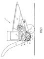
- the crusher 1, designated as a whole in FIG. 1, includes a feed zone 2, and an ejection zone 3.
- the material treated thus circulates in the grinder 1 from the feed zone 2 to the ejection zone 3 in a direction of progression passing through a chamber intermediate 4 located between the feed zone 2 and the ejection zone 3, which is intended to be equipped with the grinding means.
- the latter are advantageously constituted by a rotor with specific tools depending on the type of plants or materials to be grind.
- these grinding means consist of a rotor 5 on which are alternately arranged, cutting tools 6, intended for grinding a type of plant, and cutting tools defibration or bursting 7, intended for the grinding of other types of plants or hard materials, as well as ventilation means 15, allowing the evacuation of plants or other crushed materials out of said bedroom.
- a versatile active drum is thus obtained.
- Said ventilation means 15 are, for example, separate said cutting tools 6 and said defibering or splitting tools 7.
- said ventilation means 15 are positioned, in particular, so as to define the template of the fragments of plants or other materials sliced by said cutting tools 6.
- Said cutting tools 6, said defibering tools or burst 7 and said ventilation means 15 are positioned one relative to the others, depending on the direction of rotation of the rotor, for example, so as to successively authorize defibration or bursting, the definition of cuts sliced fragments, cuts and disposes of plants or other crushed materials.
- the said plants or other materials are thus treated upon entering chamber 4 so as to authorize their grinding to a level fine enough to be evacuated directly, without having to stay at rotor contact. This promotes the absence of stuffing.
- Cutting tools 6 and / or defibering tools or burst 7 are positioned so as to present a zone of action on plants or other materials substantially parallel to the axis 9 of rotation of the rotor while said ventilation means 15 are, at least partially, radial.
- Cutting tools 6 consist of knives on the rotor 5, and act tangentially in the direction of rotation F of said rotor 5. They intervene effectively to cut branches of medium or large diameter in the form, for example, of fragments having the section of the branch treated and given thickness.
- the defibration or bursting tools 7 are constituted by flails hinging freely on a fixed hinge pin 8, and extending parallel to the axis 9 of the rotor 5 to act so tangential under the effect of the centrifugal force acting in the direction of rotation of the rotor 5, and intervening for their part to defiberate the comer, the leaves, grass or small branches and burst hard materials such as stones or pebbles. Thanks to their free articulation, they retract when they meet branches of medium or large diameter, these being processed by the cutting tools when they in turn meet said branches. Said defibration or bursting tools 7 are possibly free to rotate all around their axis of articulation 8.
- the rotor 5 comprises at its periphery in particular two series of knives 6 1 , 6 2 , diametrically opposite, extending along two axial lines corresponding substantially to two generatrices of the rotor 5, as shown in the right-hand area of the figure 5.
- the rotor 5 has at its periphery in particular two series of flails 7 1 , 7 2 , diametrically opposed, extending along two axial lines, corresponding substantially to two generatrices of the rotor 5, but which are advantageously offset by 90 ° relative to the knife cutting lines 6.
- the flails 7 1 , of a defibration and burst line are themselves in particular offset axially with respect to those of another line 7 2 of defibration and opposite burst, so as to obtain a better effectiveness of plagues 7 regardless of the introduction of plants into the feeding zone 2.
- the zones attack 7a of the plagues 7 of two defibration and burst lines opposite are diametrically spaced at a distance D 'greater than that D "of the attack zones 6a of the knives 6 of the two cutting lines, of so as to obtain, by rotation, two virtual working cylinders, one of which C ' defibration and bursting acts on the plant or material beforehand to the other C "cutting.
- the flails 7 constituting the defibration and bursting tools are constituted by weights eccentric with respect to their articulated axis 8 integral rotor 5.
- the cutting zones 7a are reported on these weights by mechanical means making them removable to allow their interchangeability in case of wear.
- Said ventilation means are constituted, for example, at least one pale 16.
- the rotor comprises, in particular, two said blades 16, symmetrical with respect to the axis 9 of rotation rotor.
- Said blades 16 are made, for example, a proximal portion 17 a radial extending from said axis 9 of rotation of the rotor up to about half the radius of said rotor, and a distal portion 17 b, s' extending in the extension of said proximal portion 17a toward the periphery of the rotor in a curve according to the direction opposite the direction of rotation of the rotor.
- each blade is oriented, in particular along the perpendicular bisector of two cutting tools 6 and defibration and bursting tools 7, the distal part 17 b having a distal edge 18 just upstream of said cutting tools 6 , depending on the direction of rotation of the rotor.
- the blades 16 thus define, as it were, housings 19 in which the hammers 7 are movable.
- a cutter bar 10 extending axially to the rotor 5 and lying at a substantially corresponding radial distance R from it, and at most equal, to the radius R 'of the base surface of the virtual working cylinder C', of defibration and bursting.
- the bar 10 in fact constitutes a section wearing part square that can be rotated 90 ° when one of its faces is worn, which quadruples its lifespan.
- the shredder 1A differs from the previous one in that it includes a second rotor 5A constituting a second active drum, identical to the first, which is arranged on the same axis in order to constitute a double rotor.
- the second rotor 5A is angularly offset by 90 ° relative to the first 5, by so that the knives 6 of a cutting line of the first rotor are especially offset from those of another cutting line of the second rotor for greater cutting efficiency, regardless of introduction of the branch.
- Figure 5 shows not only the latter characteristic but also the fact that the plagues 7 are offset also axially with respect to each other of a defibration line and burst to another.
- the assembly thus constituted, whether it is a single rotor or a rotor double, creates an air flow ejecting the crushed plants towards the area 2.
- the particles of plants or materials are thus ejected after grinding and allow the grinder to be released, without any additional filtering and / or extraction.
Abstract
Description
La présente invention concerne un broyeur, notamment destiné à la réduction de végétaux ou autres matériaux, tels que notamment branches.The present invention relates to a grinder, in particular intended for the reduction of plants or other materials, such as in particular branches.
Toutefois, bien que plus particulièrement prévu pour de telles applications, le broyeur selon l'invention pourra également être utilisé pour broyer d'autres produits.However, although more particularly intended for such applications, the mill according to the invention can also be used for grind other products.
De tels broyeurs sont communément utilisés pour l'entretien des parcs et jardins, où l'on est amené à traiter de grandes quantités de végétaux, découpés ou morts. Ceux-ci sont particulièrement encombrants, et pour faciliter leur élimination, et/ou leur transport vers des zones de stockage ou de traitement, il est préférable de diminuer leur volume en les réduisant en morceaux.Such shredders are commonly used for maintenance parks and gardens, where large quantities of vegetable, cut or dead. These are particularly bulky, and to facilitate their disposal, and / or their transport to storage areas or treatment, it is preferable to reduce their volume by reducing them by parts.
Pour cela, on connaít des dispositifs de broyage comprenant une zone d'alimentation et une zone d'éjection, entre lesquelles est ménagée une chambre équipée de moyens de broyage, qui sont constitués par un rotor comportant sur sa périphérie des outils spécifiques selon le type de végétaux ou matériaux à broyer.For this, we know grinding devices comprising a feed area and an ejection area, between which is provided a chamber equipped with grinding means, which are constituted by a rotor comprising on its periphery specific tools according to the type of plant or materials to be ground.
Afin de broyer efficacement des branches de moyen ou de gros diamètre, par exemple de 5 à 20 cm, il est connu d'utiliser des broyeurs à couteaux qui sont destinés à effectuer des coupes transversales sur lesdites branches.In order to effectively crush branches of medium or large diameter, for example from 5 to 20 cm, it is known to use grinders with knives which are intended to make cross cuts on said branches.
Pour encore les petites branches, par exemple jusque 5 cm, des broyeurs à fléaux sont préférés, car les fléaux exercent contre le tout-venant, les feuilles, l'herbe ou, lesdites petites branches un travail de défibrage du bois assurant sa réduction.For still small branches, for example up to 5 cm, flail crushers are preferred, because the plagues exert against the comer, leaves, grass or, said small branches a work of defibration of the wood ensuring its reduction.
La difficulté réside dans le fait qu'il est nécessaire d'effectuer un tri des végétaux ou matériaux à broyer si l'on ne veut pas détériorer les moyens de broyage à couteaux, qui se dégradent rapidement en présence de pierres ou cailloux, ou si l'on souhaite une bonne efficacité des moyens de broyage.The difficulty lies in the fact that it is necessary to perform sorting the plants or materials to be ground if one does not want to damage the knife grinding means, which degrade rapidly in the presence of stones or pebbles, or if good efficiency is desired grinding.
Des broyeurs autres que des broyeurs à rotor sont d'ailleurs le plus souvent utilisés pour le traitement des végétaux. Ils ne sont cependant pas entièrement satisfaisants.Shredders other than rotor shredders are also most often used for the treatment of plants. They are however not entirely satisfactory.
Un problème rencontré avec l'ensemble des broyeurs connus réside en effet dans l'apparition de phénomènes de bourrage dans la chambre de broyage.A problem encountered with all known shredders indeed resides in the appearance of stuffing phenomena in the grinding chamber.
Le but de la présente invention est de proposer un broyeur pour réduire les végétaux tels que, notamment des branches dénudées ou non, des arbustes ou autres matériaux et de permettre d'augmenter le rendement dudit broyeur, c'est-à-dire capable de broyer tout autant des branches de petit diamètre que des branches de gros diamètre, et ne faisant pas obstacle à la présence de pierres ou cailloux ou de tous autres matériaux durs.The object of the present invention is to provide a grinder to reduce plants such as, in particular bare branches or no, shrubs or other materials and allow to increase the yield of said grinder, that is to say capable of grinding just as much branches of small diameter only branches of large diameter, and only no obstacle to the presence of stones or pebbles or any other material hard.
La présente invention permet d'atteindre ces buts et concerne à cet effet un broyeur, notamment destiné à la réduction de végétaux ou autres matériaux, comprenant une zone d'alimentation et une zone d'éjection, entre lesquelles est ménagée une chambre équipée de moyens de broyage, qui sont constitués par un rotor comportant des outils spécifiques selon le type de végétaux ou matériaux à broyer, caractérisé en ce que sur un même rotor, sont disposés en alternance des outils de coupe, destinés au broyage d'un type de végétaux, et/ou des outils de défibrage ou d'éclatement, destinés au broyage d'autres types de végétaux, ou matériaux durs, ainsi que des moyens de ventilation, permettant l'évacuation des végétaux ou autres matériaux broyés hors de ladite chambre, de manière à constituer un tambour actif polyvalent.The present invention achieves these goals and relates to for this purpose a grinder, in particular intended for the reduction of plants or other materials, including a feeding zone and an ejection zone, between which is provided a chamber equipped with grinding means, which consist of a rotor comprising specific tools according to the type of plants or materials to be ground, characterized in that on the same rotor, are alternately arranged cutting tools, intended for grinding of a type of plant, and / or defibration or bursting tools, intended grinding other types of plants, or hard materials, as well as means of ventilation, allowing the evacuation of plants or other materials crushed outside said chamber, so as to constitute a drum versatile asset.
La présente invention concerne également les caractéristiques qui ressortiront au cours de la description qui va suivre, et qui devront être considérés isolément ou selon toutes leurs combinaisons techniques possibles.The present invention also relates to characteristics which will emerge during the description which follows, and which should be considered in isolation or in any combination possible techniques.
Cette description donnée à titre d'exemple non limitatif fera mieux comprendre comment l'invention peut être réalisée en référence aux dessins annexés sur lesquels :
- la figure 1 est une vue schématique en coupe longitudinale d'un broyeur selon l'invention,
- la figure 2 est une vue d'un rotor polyvalent selon la figure 1,
- la figure 3 est une vue du rotor selon la figure 2, lors de l'attaque d'un matériau dur,
- la figure 4 est une vue du rotor selon la figure 2, lors de l'attaque d'une branche de gros diamètre,
- la figure 5 est une vue longitudinale d'un rotor double selon une variante de réalisation,
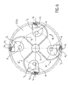
- la figure 6 est une vue transversale selon la figure 5,
- la figure 7 reprend en perspective le rotor de la figure 5.
- FIG. 1 is a schematic view in longitudinal section of a mill according to the invention,
- FIG. 2 is a view of a multipurpose rotor according to FIG. 1,
- FIG. 3 is a view of the rotor according to FIG. 2, during the attack of a hard material,
- FIG. 4 is a view of the rotor according to FIG. 2, during the attack on a branch of large diameter,
- FIG. 5 is a longitudinal view of a double rotor according to an alternative embodiment,
- FIG. 6 is a transverse view according to FIG. 5,
- FIG. 7 shows in perspective the rotor of FIG. 5.
Le broyeur 1, désigné dans son ensemble à la figure 1,
comprend une zone d'alimentation 2, et une zone d'éjection 3. La matière
traitée circule ainsi dans le broyeur 1 en allant de la zone d'alimentation 2 à la
zone d'éjection 3 selon un sens de progression passant par une chambre
intermédiaire 4 située entre la zone d'alimentation 2 et la zone d'éjection 3,
qui est destinée à être équipée des moyens de broyage.The
Ces derniers sont avantageusement constitués par un rotor comportant des outils spécifiques selon le type de végétaux ou matériaux à broyer.The latter are advantageously constituted by a rotor with specific tools depending on the type of plants or materials to be grind.
Plus précisément, selon l'invention, ces moyens de broyage
sont constitués par un rotor 5 sur lequel sont disposés en alternance, des
outils de coupe 6, destinés au broyage d'un type de végétaux, et des outils de
défibrage ou d'éclatement 7, destinés au broyage d'autres types de végétaux
ou matériaux durs, ainsi que des moyens de ventilation 15, permettant
l'évacuation des végétaux ou autres matériaux broyés hors de ladite
chambre.More specifically, according to the invention, these grinding means
consist of a
Il est obtenu ainsi un tambour actif polyvalent.A versatile active drum is thus obtained.
Lesdits moyens de ventilation 15 sont, par exemple, distincts
desdits outils de coupe 6 et desdits outils de défibrage ou d'éclatement 7.Said ventilation means 15 are, for example, separate
said
Comme illustré à la figure 2, lesdits moyens de ventilation 15
sont positionnés, notamment, de façon à définir le gabarit des fragments de
végétaux ou autres matériaux tranchés par lesdits outils de coupe 6.As illustrated in FIG. 2, said ventilation means 15
are positioned, in particular, so as to define the template of the fragments of
plants or other materials sliced by said
Lesdits outils de coupe 6, lesdits outils de défibrage ou
d'éclatement 7 et lesdits moyens de ventilation 15 sont positionnés les uns
par rapport aux autres, selon le sens de rotation du rotor, par exemple, de
façon à autoriser successivement le défibrage ou l'éclatement, la définition du
gabrit des fragments tranchés, la coupe et l'évacuation des végétaux ou
autres matériaux broyés. On traite ainsi lesdits végétaux ou autres matériaux
dès leur entrée dans la chambre 4 de façon à autoriser leur broyage à un
niveau suffisamment fin pour être évacués directement, sans avoir à rester au
contact du rotor. On favorise de la sorte l'absence de bourrage.Said
Les outils de coupe 6 et/ou les outils de défibrage ou
d'éclatement 7 sont positionnés de façon à présenter une zone d'action sur
les végétaux ou autres matériaux sensiblement parallèle à l'axe 9 de rotation
du rotor tandis que lesdits moyens de ventilation 15 sont, au moins
partiellement, radiaux.
Les outils de coupe 6 sont constitués par des couteaux sur le
rotor 5, et agissent de manière tangentielle dans le sens de rotation F dudit
rotor 5. Ils interviennent efficacement pour couper des branches de moyen ou
de gros diamètre sous la forme, par exemple, de fragments présentant la
section de la branche traitée et d'épaisseur donnée.
Par contre, les outils de défibrage ou d'éclatement 7 sont
constitués par des fléaux s'articulant librement sur un axe d'articulation fixe 8,
et s'étendant parallèlement à l'axe 9 du rotor 5 pour agir de manière
tangentielle sous l'effet de la force centrifuge agissant dans le sens de
rotation du rotor 5, et intervenant quant à eux pour défibrer le tout-venant, les
feuilles, l'herbe ou les petites branches et éclater les matériaux durs tels que
des pierres ou cailloux. Grâce à leur articulation libre, ils s'escamotent
lorsqu'ils rencontrent des branches de moyen ou gros diamètre, celles-ci
étant traitées par les outils de coupe lorsqu'ils rencontrent à leur tour lesdites
branches. Lesdits outils de défibrage ou d'éclatement 7 sont éventuellement
libres en rotation tout autour de leur axe d'articulation 8.On the other hand, the defibration or bursting
En fait, le rotor 5 comporte à sa périphérie notamment deux
séries de couteaux 61, 62, diamétralement opposés, s'étendant suivant deux
lignes axiales correspondant sensiblement à deux génératrices du rotor 5,
comme le montre la zone de droite de la figure 5.In fact, the
Egalement, le rotor 5 comporte à sa périphérie notamment
deux séries de fléaux 71, 72, diamétralement opposés, s'étendant suivant
deux lignes axiales, correspondant sensiblement à deux génératrices du rotor
5, mais qui sont avantageusement décalées de 90 ° par rapport aux lignes de
coupe des couteaux 6.Also, the
En outre, les fléaux 71, d'une ligne de défibrage et
d'éclatement sont eux-mêmes notamment décalés axialement par rapport à
ceux d'une autre ligne 72 de défibrage et d'éclatement opposée, de manière à
obtenir une meilleure efficacité des fléaux 7 quelle que soit l'introduction des
végétaux dans la zone d'alimentation 2.In addition, the
Selon une autre caractéristique de l'invention, les zones
d'attaque 7a des fléaux 7 de deux lignes de défibrage et d'éclatement
opposées sont diamétralement espacées selon une distance D' supérieure à
celle D" des zones d'attaque 6a des couteaux 6 des deux lignes de coupe, de
manière à obtenir, par rotation, deux cylindres virtuels de travail dont l'un C'
de défibrage et d'éclatement agit sur le végétal ou le matériau préalablement
à l'autre C" de coupe.According to another characteristic of the invention, the zones
attack 7a of the
C'est précisément ce dépassement radial « r » (R' - R")des
fléaux 7 par rapport aux couteaux 6 qui permettra de préserver ces derniers
lors de la présence d'un caillou ou d'une pierre dans le tout-venant au
moment de l'introduction dans la zone d'alimentation.It is precisely this radial overshoot "r" (R '- R ") of the
Comme le montrent particulièrement bien les figures, les
fléaux 7 constituant les outils de défibrage et d'éclatement sont constitués par
des masselottes excentrées par rapport à leur axe d'articulation 8 solidaires
du rotor 5.As the figures show particularly well, the
En fait, les zones de coupe 7a sont rapportée sur ces
masselottes par des moyens mécaniques permettant de les rendre amovibles
afin de permettre leur interchangeabilité en cas d'usure.In fact, the
Il en est de même pour les couteaux 6 qui sont reliés au rotor
5 par l'intermédiaire de moyens mécaniques permettant leur
interchangeabilité également.It is the same for the
Lesdits moyens de ventilation sont constitués, par exemple,
d'au moins une pâle 16. Comme illustré à la figure 2, le rotor comprend,
notamment, deuxdites pâles 16, symétriques par rapport à l'axe 9 de rotation
du rotor.Said ventilation means are constituted, for example,
at least one pale 16. As illustrated in FIG. 2, the rotor comprises,
in particular, two said
Lesdites pâles 16 sont constituées, par exemple, d'une partie
proximale 17a radiale, s'étendant dudit axe 9 de rotation du rotor jusqu'à
environ la moitié du rayon dudit rotor, et d'une partie distale 17b, s'étendant
dans le prolongement de ladite partie proximale 17a vers la périphérie du
rotor, en s'incurvant selon le sens opposé au sens de rotation du rotor.Said
Ladite partie proximale 17a de chaque pâle est orientée,
notamment selon la médiatrice de deux outils de coupe 6 et outils de
défibrage et d'éclatement 7 successifs, la partie distale 17b présentant un
rebord distal 18 juste en amont desdits outils de coupe 6, selon le sens de
rotation du rotor. Les pâles 16 définissent ainsi, en quelque sorte, des
logements 19 dans lesquels les marteaux 7 sont mobiles.Said
Selon une autre caractéristique de l'invention,
particulièrement bien visible sur les figures 3 et 4, dans une zone limitrophe
de la zone d'alimentation 2 et de la chambre de broyage 4, est disposée
fixement une barre de coupe 10 s'étendant axialement au rotor 5 et se situant
à une distance radiale R de celui-ci, sensiblement correspondant, et au plus
égale, au rayon R' de la surface de base du cylindre virtuel de travail C', de
défibrage et d'éclatement.According to another characteristic of the invention,
particularly well visible in Figures 3 and 4, in a bordering area
the
La barre 10 constitue en fait une pièce d'usure de section
carrée pouvant être tournée de 90° quand une de ses faces est usée, ce qui
multiplie par quatre sa durée de vie.The
A noter également que la différence « r' » entre le rayon R"'
du voile du tambour du rotor 5, correspondant au bord distal 18 des pâles 16,
sur lequel l'extrémité des branches vont buter et le rayon R" de la surface de
base du cylindre virtuel de coupe C" est égale à l'épaisseur de coupe
souhaitée (R" - R"' = r' = épaisseur de coupe).Also note that the difference "r '" between the radius R "'
the veil of the
Selon une variante de réalisation, représentée sur les figures
5 et 6, le broyeur 1A se distingue du précédent en ce qu'il comporte un
second rotor 5A constituant un second tambour actif, identique au premier,
qui est disposé sur le même axe afin de constituer un rotor double.According to an alternative embodiment, shown in the figures
5 and 6, the
Comme le montre particulièrement bien la figure 5, le second
rotor 5A est angulairement décalé de 90 ° par rapport au premier 5, de
manière à ce que les couteaux 6 d'une ligne de coupe du premier rotor soient
notamment décalés par rapport à ceux d'une autre ligne de coupe du second
rotor pour une plus grande efficacité de coupe, quelle que soit l'introduction
de la branche.As shown particularly well in Figure 5, the
La figure 5 permet de visualiser non seulement cette dernière
caractéristique mais également le fait que les fléaux 7 sont décalés
également axialement les uns par rapport aux autres d'une ligne de défibrage
et d'éclatement à une autre.Figure 5 shows not only the latter
characteristic but also the fact that the
D'une manière générale, l'alternance des lignes de couteaux
6, des lignes de fléaux 7 et des pâles 16 sur un même rotor 5 ou 5A et le
décalage angulaire d'un rotor 5 par rapport à un autre 5A identique permet
d'obtenir un équilibrage pour une machine travaillant sans saccade et sans
vibration.Generally speaking, the alternation of
L'ensemble ainsi constitué, qu'il soit à rotor simple ou à rotor
double, crée un flux d'air éjectant les végétaux broyés en direction de la zone
d'éjection 2. Les particules de végétaux ou de matériaux sont ainsi éjectés
après broyage et permettent la libération du broyeur, sans équipement de
filtrage et/ou d'extraction supplémentaire.The assembly thus constituted, whether it is a single rotor or a rotor
double, creates an air flow ejecting the crushed plants towards the
Bien naturellement, les dispositions qui viennent d'être décrites peuvent être adaptées, sans sortir de la présente invention notamment quant au nombre de couteaux et/ou de fléaux et/ou rotors.Naturally, the provisions which have just been described can be adapted without departing from the present invention in particular as to the number of knives and / or flails and / or rotors.
Claims (10)
Applications Claiming Priority (2)
| Application Number | Priority Date | Filing Date | Title |
|---|---|---|---|
| FR9908736 | 1999-07-01 | ||
| FR9908736A FR2795661B1 (en) | 1999-07-01 | 1999-07-01 | CRUSHER, ESPECIALLY FOR REDUCING PLANTS OR OTHER MATERIALS |
Publications (2)
| Publication Number | Publication Date |
|---|---|
| EP1066883A1 true EP1066883A1 (en) | 2001-01-10 |
| EP1066883B1 EP1066883B1 (en) | 2008-10-08 |
Family
ID=9547782
Family Applications (1)
| Application Number | Title | Priority Date | Filing Date |
|---|---|---|---|
| EP00490026A Expired - Lifetime EP1066883B1 (en) | 1999-07-01 | 2000-06-30 | Shredding apparatus for vegetal or other material |
Country Status (4)
| Country | Link |
|---|---|
| EP (1) | EP1066883B1 (en) |
| AT (1) | ATE410233T1 (en) |
| DE (1) | DE60040435D1 (en) |
| FR (1) | FR2795661B1 (en) |
Cited By (7)
| Publication number | Priority date | Publication date | Assignee | Title |
|---|---|---|---|---|
| FR2912326A1 (en) * | 2007-02-14 | 2008-08-15 | Bugnot 55 Soc Par Actions Simp | Plant grinding tool for plant grinder, has pendular flyweights articulated around axis of rotor and includes active end with front face located behind plan passed through apex of step and articulation center of flyweight |
| FR2954673A1 (en) * | 2009-12-28 | 2011-07-01 | Michel Bugnot | Rotor for plant crusher, has opening arranged in spacing partition formed upstream of two openings with respect to rotation direction of rotor, and reduction tool that is housed in bracing space |
| EP2363017A1 (en) | 2009-12-24 | 2011-09-07 | Rabaud | Vegetable grinding device |
| FR2973721A1 (en) * | 2011-04-06 | 2012-10-12 | Michel Bugnot | Plants shredder, has finger comprising section passed via bore and terminated in orifice of wall to fix tool with rotor, and another section having diameter larger than that of former section and cooperating with orifice of another wall |
| EP2669013A1 (en) | 2012-05-31 | 2013-12-04 | Rabaud | Improvement to plant mills |
| AT511662B1 (en) * | 2010-02-17 | 2014-04-15 | Kesla Oyj | Rotor for a cutting machine |
| FR3010330A1 (en) * | 2013-09-09 | 2015-03-13 | Michel Bugnot | VEGETABLE MILLER |
Families Citing this family (2)
| Publication number | Priority date | Publication date | Assignee | Title |
|---|---|---|---|---|
| DE10305535B3 (en) * | 2003-02-11 | 2004-08-12 | Werner Kress | Shredding machine for garden refuse has filling shaft and discharge shaft on opposite sides of shredding device with shredding blade |
| FR2948582B1 (en) | 2009-07-31 | 2011-08-19 | Kiva | DEVICE FOR GRINDING PLANTS. |
Citations (7)
| Publication number | Priority date | Publication date | Assignee | Title |
|---|---|---|---|---|
| FR943110A (en) * | 1947-02-24 | 1949-02-28 | Machine for milling straw, fodder and the like | |
| US3724767A (en) * | 1971-10-07 | 1973-04-03 | Piqua Eng Inc | Shredder-grinder machine having an improved rotor |
| DE9113277U1 (en) * | 1991-10-25 | 1992-01-30 | Haas, Volker, 5439 Stockum-Pueschen, De | |
| US5189868A (en) * | 1992-03-23 | 1993-03-02 | Jerry Hill | Leaf mulcher |
| DE9410330U1 (en) * | 1994-06-27 | 1994-09-15 | Doppstadt Werner | Flail drum for a shredding machine |
| US5413286A (en) * | 1992-04-27 | 1995-05-09 | Tramor, Inc. | Waste processing machine |
| WO2000013797A1 (en) * | 1998-09-03 | 2000-03-16 | Bartlem Pty. Ltd. | Garden refuse shredding apparatus |
-
1999
- 1999-07-01 FR FR9908736A patent/FR2795661B1/en not_active Expired - Fee Related
-
2000
- 2000-06-30 EP EP00490026A patent/EP1066883B1/en not_active Expired - Lifetime
- 2000-06-30 DE DE60040435T patent/DE60040435D1/en not_active Expired - Lifetime
- 2000-06-30 AT AT00490026T patent/ATE410233T1/en not_active IP Right Cessation
Patent Citations (7)
| Publication number | Priority date | Publication date | Assignee | Title |
|---|---|---|---|---|
| FR943110A (en) * | 1947-02-24 | 1949-02-28 | Machine for milling straw, fodder and the like | |
| US3724767A (en) * | 1971-10-07 | 1973-04-03 | Piqua Eng Inc | Shredder-grinder machine having an improved rotor |
| DE9113277U1 (en) * | 1991-10-25 | 1992-01-30 | Haas, Volker, 5439 Stockum-Pueschen, De | |
| US5189868A (en) * | 1992-03-23 | 1993-03-02 | Jerry Hill | Leaf mulcher |
| US5413286A (en) * | 1992-04-27 | 1995-05-09 | Tramor, Inc. | Waste processing machine |
| DE9410330U1 (en) * | 1994-06-27 | 1994-09-15 | Doppstadt Werner | Flail drum for a shredding machine |
| WO2000013797A1 (en) * | 1998-09-03 | 2000-03-16 | Bartlem Pty. Ltd. | Garden refuse shredding apparatus |
Cited By (7)
| Publication number | Priority date | Publication date | Assignee | Title |
|---|---|---|---|---|
| FR2912326A1 (en) * | 2007-02-14 | 2008-08-15 | Bugnot 55 Soc Par Actions Simp | Plant grinding tool for plant grinder, has pendular flyweights articulated around axis of rotor and includes active end with front face located behind plan passed through apex of step and articulation center of flyweight |
| EP2363017A1 (en) | 2009-12-24 | 2011-09-07 | Rabaud | Vegetable grinding device |
| FR2954673A1 (en) * | 2009-12-28 | 2011-07-01 | Michel Bugnot | Rotor for plant crusher, has opening arranged in spacing partition formed upstream of two openings with respect to rotation direction of rotor, and reduction tool that is housed in bracing space |
| AT511662B1 (en) * | 2010-02-17 | 2014-04-15 | Kesla Oyj | Rotor for a cutting machine |
| FR2973721A1 (en) * | 2011-04-06 | 2012-10-12 | Michel Bugnot | Plants shredder, has finger comprising section passed via bore and terminated in orifice of wall to fix tool with rotor, and another section having diameter larger than that of former section and cooperating with orifice of another wall |
| EP2669013A1 (en) | 2012-05-31 | 2013-12-04 | Rabaud | Improvement to plant mills |
| FR3010330A1 (en) * | 2013-09-09 | 2015-03-13 | Michel Bugnot | VEGETABLE MILLER |
Also Published As
| Publication number | Publication date |
|---|---|
| FR2795661B1 (en) | 2001-09-07 |
| EP1066883B1 (en) | 2008-10-08 |
| DE60040435D1 (en) | 2008-11-20 |
| ATE410233T1 (en) | 2008-10-15 |
| FR2795661A1 (en) | 2001-01-05 |
Similar Documents
| Publication | Publication Date | Title |
|---|---|---|
| US11173496B2 (en) | Flywheel and paddle assembly for a chipping or shredding apparatus, and an apparatus incorporating same | |
| EP1066883B1 (en) | Shredding apparatus for vegetal or other material | |
| HU220979B1 (en) | Rotor cutter | |
| EP1776856B1 (en) | Vegetation cutter | |
| EP1261250B1 (en) | Vegetable product shredding apparatus | |
| EP1903855B1 (en) | Device for pruning and shredding plants | |
| EP0620043A2 (en) | Desintegrator for solid objects | |
| US10882051B1 (en) | Mulcher with improved cutting drum | |
| WO1993023988A1 (en) | Machine for the destruction of banana plantation | |
| EP0290556B1 (en) | Combined implement for crushing, grubbing, decompaction and working of the soil | |
| FR2508344A1 (en) | WASTE SHREDDER WITH HELICOIDAL SIZE | |
| FR2715267A1 (en) | Device intended to be combined with a disc bar for the purpose of chopping and / or crushing plants. Disc bar cutting machine equipped with such a device. | |
| EP0420731A1 (en) | Knifecrusher-shredder for refuse | |
| US6945025B2 (en) | Shredder head with protective elements, and mobile sylvicultural apparatus including the same | |
| FR2698237A1 (en) | Grass cutting machine, - Has flail device to progressively reduce the height of grass, with separate final level cutter. | |
| WO2009004252A2 (en) | Pruner-chopper device | |
| FR2685993A1 (en) | Machine for cutting plants, particularly forestry shredder | |
| FR2937829A1 (en) | Mounted/semi-mounted type agricultural plants shredding and crushing device i.e. bi-rotor shredder/crusher, for use with tractor vehicle, has cutting tool assuring shredding/crushing action along its active width equal to width of space | |
| EP2949438B1 (en) | Plant mill for producing gauged particles | |
| EP1072314A1 (en) | Form of the active part of a knife for a knife-crusher | |
| FR2522535A1 (en) | Crusher for agriculture or forestry - has rotating drum and folding hammers with transverse movement | |
| FR2511893A1 (en) | Cutting cylinder for rotary cutting machine - employs staggered knives to ensure cylinder edges are kept clear of debris | |
| FR2744874A1 (en) | Leaf cutting machine used in agriculture for ground vegetation | |
| FR2691079A1 (en) | Compact refuse grinder - has shaft carrying shredding wheels at bottom of first hopper and second hopper housing grinding drum with granulating teeth | |
| FR2655569A1 (en) | Small size shredder (crusher) for plants, with differential-speed drive |
Legal Events
| Date | Code | Title | Description |
|---|---|---|---|
| PUAI | Public reference made under article 153(3) epc to a published international application that has entered the european phase |
Free format text: ORIGINAL CODE: 0009012 |
|
| AK | Designated contracting states |
Kind code of ref document: A1 Designated state(s): AT BE CH CY DE DK ES FI FR GB GR IE IT LI LU MC NL PT SE |
|
| AX | Request for extension of the european patent |
Free format text: AL;LT;LV;MK;RO;SI |
|
| 17P | Request for examination filed |
Effective date: 20010702 |
|
| AKX | Designation fees paid |
Free format text: AT BE CH CY DE DK ES FI FR GB GR IE IT LI LU MC NL PT SE |
|
| 17Q | First examination report despatched |
Effective date: 20060724 |
|
| GRAP | Despatch of communication of intention to grant a patent |
Free format text: ORIGINAL CODE: EPIDOSNIGR1 |
|
| RAP1 | Party data changed (applicant data changed or rights of an application transferred) |
Owner name: SOCIETE D'EQUIPEMENTS POUR L'ENVIRONNEMENT |
|
| GRAS | Grant fee paid |
Free format text: ORIGINAL CODE: EPIDOSNIGR3 |
|
| GRAA | (expected) grant |
Free format text: ORIGINAL CODE: 0009210 |
|
| AK | Designated contracting states |
Kind code of ref document: B1 Designated state(s): AT BE CH CY DE DK ES FI FR GB GR IE IT LI LU MC NL PT SE |
|
| REG | Reference to a national code |
Ref country code: GB Ref legal event code: FG4D Free format text: NOT ENGLISH |
|
| REG | Reference to a national code |
Ref country code: CH Ref legal event code: EP |
|
| REG | Reference to a national code |
Ref country code: IE Ref legal event code: FG4D Free format text: LANGUAGE OF EP DOCUMENT: FRENCH |
|
| REF | Corresponds to: |
Ref document number: 60040435 Country of ref document: DE Date of ref document: 20081120 Kind code of ref document: P |
|
| REG | Reference to a national code |
Ref country code: SE Ref legal event code: TRGR |
|
| PG25 | Lapsed in a contracting state [announced via postgrant information from national office to epo] |
Ref country code: AT Free format text: LAPSE BECAUSE OF FAILURE TO SUBMIT A TRANSLATION OF THE DESCRIPTION OR TO PAY THE FEE WITHIN THE PRESCRIBED TIME-LIMIT Effective date: 20081008 Ref country code: ES Free format text: LAPSE BECAUSE OF FAILURE TO SUBMIT A TRANSLATION OF THE DESCRIPTION OR TO PAY THE FEE WITHIN THE PRESCRIBED TIME-LIMIT Effective date: 20090119 |
|
| PG25 | Lapsed in a contracting state [announced via postgrant information from national office to epo] |
Ref country code: PT Free format text: LAPSE BECAUSE OF FAILURE TO SUBMIT A TRANSLATION OF THE DESCRIPTION OR TO PAY THE FEE WITHIN THE PRESCRIBED TIME-LIMIT Effective date: 20090217 Ref country code: FI Free format text: LAPSE BECAUSE OF FAILURE TO SUBMIT A TRANSLATION OF THE DESCRIPTION OR TO PAY THE FEE WITHIN THE PRESCRIBED TIME-LIMIT Effective date: 20081008 |
|
| REG | Reference to a national code |
Ref country code: IE Ref legal event code: FD4D |
|
| PG25 | Lapsed in a contracting state [announced via postgrant information from national office to epo] |
Ref country code: DK Free format text: LAPSE BECAUSE OF FAILURE TO SUBMIT A TRANSLATION OF THE DESCRIPTION OR TO PAY THE FEE WITHIN THE PRESCRIBED TIME-LIMIT Effective date: 20081008 Ref country code: IE Free format text: LAPSE BECAUSE OF FAILURE TO SUBMIT A TRANSLATION OF THE DESCRIPTION OR TO PAY THE FEE WITHIN THE PRESCRIBED TIME-LIMIT Effective date: 20081008 |
|
| PLBE | No opposition filed within time limit |
Free format text: ORIGINAL CODE: 0009261 |
|
| STAA | Information on the status of an ep patent application or granted ep patent |
Free format text: STATUS: NO OPPOSITION FILED WITHIN TIME LIMIT |
|
| 26N | No opposition filed |
Effective date: 20090709 |
|
| PGFP | Annual fee paid to national office [announced via postgrant information from national office to epo] |
Ref country code: LU Payment date: 20090720 Year of fee payment: 10 |
|
| PG25 | Lapsed in a contracting state [announced via postgrant information from national office to epo] |
Ref country code: MC Free format text: LAPSE BECAUSE OF NON-PAYMENT OF DUE FEES Effective date: 20090630 |
|
| REG | Reference to a national code |
Ref country code: CH Ref legal event code: PL |
|
| PG25 | Lapsed in a contracting state [announced via postgrant information from national office to epo] |
Ref country code: CH Free format text: LAPSE BECAUSE OF NON-PAYMENT OF DUE FEES Effective date: 20090630 Ref country code: LI Free format text: LAPSE BECAUSE OF NON-PAYMENT OF DUE FEES Effective date: 20090630 |
|
| PG25 | Lapsed in a contracting state [announced via postgrant information from national office to epo] |
Ref country code: GR Free format text: LAPSE BECAUSE OF FAILURE TO SUBMIT A TRANSLATION OF THE DESCRIPTION OR TO PAY THE FEE WITHIN THE PRESCRIBED TIME-LIMIT Effective date: 20090109 |
|
| PG25 | Lapsed in a contracting state [announced via postgrant information from national office to epo] |
Ref country code: CY Free format text: LAPSE BECAUSE OF FAILURE TO SUBMIT A TRANSLATION OF THE DESCRIPTION OR TO PAY THE FEE WITHIN THE PRESCRIBED TIME-LIMIT Effective date: 20081008 |
|
| PG25 | Lapsed in a contracting state [announced via postgrant information from national office to epo] |
Ref country code: LU Free format text: LAPSE BECAUSE OF NON-PAYMENT OF DUE FEES Effective date: 20100630 |
|
| PGFP | Annual fee paid to national office [announced via postgrant information from national office to epo] |
Ref country code: SE Payment date: 20140612 Year of fee payment: 15 Ref country code: NL Payment date: 20140520 Year of fee payment: 15 |
|
| REG | Reference to a national code |
Ref country code: SE Ref legal event code: EUG |
|
| REG | Reference to a national code |
Ref country code: NL Ref legal event code: MM Effective date: 20150701 |
|
| PG25 | Lapsed in a contracting state [announced via postgrant information from national office to epo] |
Ref country code: NL Free format text: LAPSE BECAUSE OF NON-PAYMENT OF DUE FEES Effective date: 20150701 |
|
| REG | Reference to a national code |
Ref country code: FR Ref legal event code: PLFP Year of fee payment: 17 |
|
| PG25 | Lapsed in a contracting state [announced via postgrant information from national office to epo] |
Ref country code: SE Free format text: LAPSE BECAUSE OF NON-PAYMENT OF DUE FEES Effective date: 20150701 |
|
| REG | Reference to a national code |
Ref country code: FR Ref legal event code: PLFP Year of fee payment: 18 |
|
| REG | Reference to a national code |
Ref country code: FR Ref legal event code: PLFP Year of fee payment: 19 |
|
| PGFP | Annual fee paid to national office [announced via postgrant information from national office to epo] |
Ref country code: IT Payment date: 20190614 Year of fee payment: 20 Ref country code: DE Payment date: 20190611 Year of fee payment: 20 |
|
| PGFP | Annual fee paid to national office [announced via postgrant information from national office to epo] |
Ref country code: FR Payment date: 20190426 Year of fee payment: 20 Ref country code: BE Payment date: 20190624 Year of fee payment: 20 |
|
| PGFP | Annual fee paid to national office [announced via postgrant information from national office to epo] |
Ref country code: GB Payment date: 20190620 Year of fee payment: 20 |
|
| REG | Reference to a national code |
Ref country code: DE Ref legal event code: R071 Ref document number: 60040435 Country of ref document: DE |
|
| REG | Reference to a national code |
Ref country code: GB Ref legal event code: PE20 Expiry date: 20200629 |
|
| REG | Reference to a national code |
Ref country code: BE Ref legal event code: MK Effective date: 20200630 |
|
| PG25 | Lapsed in a contracting state [announced via postgrant information from national office to epo] |
Ref country code: GB Free format text: LAPSE BECAUSE OF EXPIRATION OF PROTECTION Effective date: 20200629 |