EP3141785B1 - Valve device - Google Patents
Valve device Download PDFInfo
- Publication number
- EP3141785B1 EP3141785B1 EP15789602.8A EP15789602A EP3141785B1 EP 3141785 B1 EP3141785 B1 EP 3141785B1 EP 15789602 A EP15789602 A EP 15789602A EP 3141785 B1 EP3141785 B1 EP 3141785B1
- Authority
- EP
- European Patent Office
- Prior art keywords
- outside
- case
- hole
- top portion
- valve
- Prior art date
- Legal status (The legal status is an assumption and is not a legal conclusion. Google has not performed a legal analysis and makes no representation as to the accuracy of the status listed.)
- Active
Links
- 230000035515 penetration Effects 0.000 claims description 31
- 239000002828 fuel tank Substances 0.000 claims description 17
- 210000000078 claw Anatomy 0.000 claims description 13
- 238000009423 ventilation Methods 0.000 claims description 9
- 239000000446 fuel Substances 0.000 description 12
- 230000000630 rising effect Effects 0.000 description 9
- 230000002093 peripheral effect Effects 0.000 description 4
- 239000004033 plastic Substances 0.000 description 4
- 238000004891 communication Methods 0.000 description 2
- 239000004020 conductor Substances 0.000 description 2
- 238000005452 bending Methods 0.000 description 1
- 230000000903 blocking effect Effects 0.000 description 1
- 230000006835 compression Effects 0.000 description 1
- 238000007906 compression Methods 0.000 description 1
- 230000000694 effects Effects 0.000 description 1
- 230000005489 elastic deformation Effects 0.000 description 1
- 238000005516 engineering process Methods 0.000 description 1
- 238000003780 insertion Methods 0.000 description 1
- 230000037431 insertion Effects 0.000 description 1
- 239000000463 material Substances 0.000 description 1
- 238000000034 method Methods 0.000 description 1
- 230000000149 penetrating effect Effects 0.000 description 1
- 238000007789 sealing Methods 0.000 description 1
- 238000000926 separation method Methods 0.000 description 1
- 238000003466 welding Methods 0.000 description 1
Images


Classifications
-
- F—MECHANICAL ENGINEERING; LIGHTING; HEATING; WEAPONS; BLASTING
- F02—COMBUSTION ENGINES; HOT-GAS OR COMBUSTION-PRODUCT ENGINE PLANTS
- F02M—SUPPLYING COMBUSTION ENGINES IN GENERAL WITH COMBUSTIBLE MIXTURES OR CONSTITUENTS THEREOF
- F02M25/00—Engine-pertinent apparatus for adding non-fuel substances or small quantities of secondary fuel to combustion-air, main fuel or fuel-air mixture
- F02M25/08—Engine-pertinent apparatus for adding non-fuel substances or small quantities of secondary fuel to combustion-air, main fuel or fuel-air mixture adding fuel vapours drawn from engine fuel reservoir
- F02M25/0836—Arrangement of valves controlling the admission of fuel vapour to an engine, e.g. valve being disposed between fuel tank or absorption canister and intake manifold
-
- B—PERFORMING OPERATIONS; TRANSPORTING
- B60—VEHICLES IN GENERAL
- B60K—ARRANGEMENT OR MOUNTING OF PROPULSION UNITS OR OF TRANSMISSIONS IN VEHICLES; ARRANGEMENT OR MOUNTING OF PLURAL DIVERSE PRIME-MOVERS IN VEHICLES; AUXILIARY DRIVES FOR VEHICLES; INSTRUMENTATION OR DASHBOARDS FOR VEHICLES; ARRANGEMENTS IN CONNECTION WITH COOLING, AIR INTAKE, GAS EXHAUST OR FUEL SUPPLY OF PROPULSION UNITS IN VEHICLES
- B60K15/00—Arrangement in connection with fuel supply of combustion engines or other fuel consuming energy converters, e.g. fuel cells; Mounting or construction of fuel tanks
- B60K15/03—Fuel tanks
- B60K15/035—Fuel tanks characterised by venting means
- B60K15/03519—Valve arrangements in the vent line
-
- F—MECHANICAL ENGINEERING; LIGHTING; HEATING; WEAPONS; BLASTING
- F02—COMBUSTION ENGINES; HOT-GAS OR COMBUSTION-PRODUCT ENGINE PLANTS
- F02M—SUPPLYING COMBUSTION ENGINES IN GENERAL WITH COMBUSTIBLE MIXTURES OR CONSTITUENTS THEREOF
- F02M37/00—Apparatus or systems for feeding liquid fuel from storage containers to carburettors or fuel-injection apparatus; Arrangements for purifying liquid fuel specially adapted for, or arranged on, internal-combustion engines
- F02M37/0076—Details of the fuel feeding system related to the fuel tank
- F02M37/0082—Devices inside the fuel tank other than fuel pumps or filters
-
- F—MECHANICAL ENGINEERING; LIGHTING; HEATING; WEAPONS; BLASTING
- F02—COMBUSTION ENGINES; HOT-GAS OR COMBUSTION-PRODUCT ENGINE PLANTS
- F02M—SUPPLYING COMBUSTION ENGINES IN GENERAL WITH COMBUSTIBLE MIXTURES OR CONSTITUENTS THEREOF
- F02M37/00—Apparatus or systems for feeding liquid fuel from storage containers to carburettors or fuel-injection apparatus; Arrangements for purifying liquid fuel specially adapted for, or arranged on, internal-combustion engines
- F02M37/20—Apparatus or systems for feeding liquid fuel from storage containers to carburettors or fuel-injection apparatus; Arrangements for purifying liquid fuel specially adapted for, or arranged on, internal-combustion engines characterised by means for preventing vapour lock
-
- F—MECHANICAL ENGINEERING; LIGHTING; HEATING; WEAPONS; BLASTING
- F16—ENGINEERING ELEMENTS AND UNITS; GENERAL MEASURES FOR PRODUCING AND MAINTAINING EFFECTIVE FUNCTIONING OF MACHINES OR INSTALLATIONS; THERMAL INSULATION IN GENERAL
- F16K—VALVES; TAPS; COCKS; ACTUATING-FLOATS; DEVICES FOR VENTING OR AERATING
- F16K24/00—Devices, e.g. valves, for venting or aerating enclosures
- F16K24/04—Devices, e.g. valves, for venting or aerating enclosures for venting only
- F16K24/042—Devices, e.g. valves, for venting or aerating enclosures for venting only actuated by a float
- F16K24/044—Devices, e.g. valves, for venting or aerating enclosures for venting only actuated by a float the float being rigidly connected to the valve element, the assembly of float and valve element following a substantially translational movement when actuated, e.g. also for actuating a pilot valve
-
- F—MECHANICAL ENGINEERING; LIGHTING; HEATING; WEAPONS; BLASTING
- F16—ENGINEERING ELEMENTS AND UNITS; GENERAL MEASURES FOR PRODUCING AND MAINTAINING EFFECTIVE FUNCTIONING OF MACHINES OR INSTALLATIONS; THERMAL INSULATION IN GENERAL
- F16K—VALVES; TAPS; COCKS; ACTUATING-FLOATS; DEVICES FOR VENTING OR AERATING
- F16K27/00—Construction of housing; Use of materials therefor
- F16K27/02—Construction of housing; Use of materials therefor of lift valves
-
- F—MECHANICAL ENGINEERING; LIGHTING; HEATING; WEAPONS; BLASTING
- F16—ENGINEERING ELEMENTS AND UNITS; GENERAL MEASURES FOR PRODUCING AND MAINTAINING EFFECTIVE FUNCTIONING OF MACHINES OR INSTALLATIONS; THERMAL INSULATION IN GENERAL
- F16K—VALVES; TAPS; COCKS; ACTUATING-FLOATS; DEVICES FOR VENTING OR AERATING
- F16K31/00—Actuating devices; Operating means; Releasing devices
- F16K31/12—Actuating devices; Operating means; Releasing devices actuated by fluid
- F16K31/18—Actuating devices; Operating means; Releasing devices actuated by fluid actuated by a float
- F16K31/20—Actuating devices; Operating means; Releasing devices actuated by fluid actuated by a float actuating a lift valve
- F16K31/22—Actuating devices; Operating means; Releasing devices actuated by fluid actuated by a float actuating a lift valve with the float rigidly connected to the valve
-
- B—PERFORMING OPERATIONS; TRANSPORTING
- B60—VEHICLES IN GENERAL
- B60K—ARRANGEMENT OR MOUNTING OF PROPULSION UNITS OR OF TRANSMISSIONS IN VEHICLES; ARRANGEMENT OR MOUNTING OF PLURAL DIVERSE PRIME-MOVERS IN VEHICLES; AUXILIARY DRIVES FOR VEHICLES; INSTRUMENTATION OR DASHBOARDS FOR VEHICLES; ARRANGEMENTS IN CONNECTION WITH COOLING, AIR INTAKE, GAS EXHAUST OR FUEL SUPPLY OF PROPULSION UNITS IN VEHICLES
- B60K15/00—Arrangement in connection with fuel supply of combustion engines or other fuel consuming energy converters, e.g. fuel cells; Mounting or construction of fuel tanks
- B60K15/03—Fuel tanks
- B60K2015/03256—Fuel tanks characterised by special valves, the mounting thereof
- B60K2015/03289—Float valves; Floats therefor
-
- B—PERFORMING OPERATIONS; TRANSPORTING
- B60—VEHICLES IN GENERAL
- B60K—ARRANGEMENT OR MOUNTING OF PROPULSION UNITS OR OF TRANSMISSIONS IN VEHICLES; ARRANGEMENT OR MOUNTING OF PLURAL DIVERSE PRIME-MOVERS IN VEHICLES; AUXILIARY DRIVES FOR VEHICLES; INSTRUMENTATION OR DASHBOARDS FOR VEHICLES; ARRANGEMENTS IN CONNECTION WITH COOLING, AIR INTAKE, GAS EXHAUST OR FUEL SUPPLY OF PROPULSION UNITS IN VEHICLES
- B60K15/00—Arrangement in connection with fuel supply of combustion engines or other fuel consuming energy converters, e.g. fuel cells; Mounting or construction of fuel tanks
- B60K15/03—Fuel tanks
- B60K2015/03328—Arrangements or special measures related to fuel tanks or fuel handling
- B60K2015/03453—Arrangements or special measures related to fuel tanks or fuel handling for fixing or mounting parts of the fuel tank together
- B60K2015/03467—Arrangements or special measures related to fuel tanks or fuel handling for fixing or mounting parts of the fuel tank together by clip or snap fit fittings
Definitions
- the present invention relates to an improvement of a valve device attached to a fuel tank of an automobile, a two-wheeled vehicle, and the like for functioning for communicating inside and outside of the fuel tank in an open valve state.
- valve device As for the valve device forming a ventilation flow channel of the fuel tank, there is a valve device including an outer sleeve, an inner sleeve, and a float, wherein the float sits on a valve opening formed in an upper portion of the outer sleeve at an elevated position (see Patent Document 1).
- the outer sleeve includes a connection portion to a conductor at an upper portion of the valve opening, and there is provided a seal member for improving a seal property at a sitting time at an upper portion of the float.
- a seal member for sealing between the connection portion of the outer sleeve and the conductor is separately required.
- Patent Document 1 U.S. Patent No. 6866058 .
- a main object of the present invention is that in this kind of valve device, parts comprising a seal function are unified so as to minimize the number of component parts of this kind of valve device, and further reduce costs.
- the present invention is a valve device as defined in claim 1.
- one of the preferred aspects of the present invention is that in either one of the case or the outside member, there is provided an engagement claw engaging an engagement hole provided in the other of the case or the outside member.
- one of the preferred aspects of the present invention is that the engagement claw is provided in the top portion of the case, and the engagement hole is provided in the top portion of the outside member.
- a flow channel through the penetration portions can meander up and down so as to prevent an outflow of a fuel to the outside of the tank in a state before the float valve sits onto the valve seat as much as possible.
- the case is formed by an outside cylinder member and an inside cylinder member combined with the outside cylinder member by forming a gap between the inside cylinder member and the outside cylinder member, and there is provided a penetration portion in a side portion of the inside cylinder member, and an upper end portion of the outside cylinder member positioned above the penetration portion becomes an open end of the gap, so that a flow channel through such open end, gap, and penetration portion can meander up and down so as to prevent the outflow of the fuel to the outside of the tank in the state before the float valve sits onto the valve seat as much as possible.
- the parts forming the seal function can be assembled with the cylindrical seal member. Therefore, the present invention can minimize the number of component parts of this kind of valve device, and further can reduce costs.
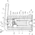
- a valve device is attached to a fuel tank of an automobile, a two-wheeled vehicle, and the like so as to form one portion of a ventilation flow channel 1 of such fuel tank, and functions for communicating inside and outside of the fuel tank in an open valve state (see Fig. 4 ).
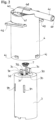
- valve device (the first example) shown in Fig. 1 to Fig. 8 is provided in the fuel tank using a bracket (not shown in the drawings) provided inside the fuel tank.
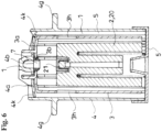
- Such valve device comprises a float valve 2, a case 3 housing the float valve 2, an outside member 4 housing the case 3, and a cap 5 closing a lower end of the outside member 4 (see Fig. 4 ).
- float valve 2, case 3, outside member 4, and cap 5 are typically made of plastic.
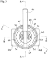
- the case 3 includes a top portion 3a and a circular first through hole 3b at a center of the top portion 3a, and substantially has a cylindrical shape wherein a lower end is open. Also, outside the top portion 3a, there is formed a pair of plate-shaped protruding portions 3c and 3c protruding upward (see Fig. 2 ). The pair of plate-shaped protruding portions 3c and 3c is disposed in such a way as to face each plate face thereof, and between the pair of plate-shaped protruding portions 3c and 3c disposed in the aforementioned manner, there is formed the first through hole 3b.
- the outside member 4 includes a top portion 4a and a circular second through hole 4b at a center of the top portion 4a, and substantially has the cylindrical shape wherein the lower end is open (see Fig. 4 ).
- Such second through hole 4b extends horizontally by integrally connecting a pipe one end 4d to the center of the top portion 4a on an upper face side of the top portion 4a of the outside member 4, and a pipe other end 4e communicates to an outside of a tank through an exhaust port 4c having a pipe shape which is a connection portion to one end of a pipe member
- Such case 3 and outside member 4 are combined in such a way as to pinch one portion of a cylindrical seal member 7 fitted in the first through hole 3b to communicate an inner portion to the second through hole 4b, between the top portion 3a of the case 3 wherein the first through hole 3b is formed, and the top portion 4a of the outside member 4 wherein the second through hole 4b is formed.
- the cylindrical seal member 7 is made of rubber or plastic having rubber-like elasticity.
- such cylindrical seal member 7 includes an outer flange portion 7a having a circular shape at a cylinder upper end (see Fig. 8 ).
- On an upper face of the outer flange portion 7a there is formed a circular projecting piece 7b.
- An outer diameter of the outer flange portion 7a is larger than a hole diameter of the first through hole 3b.
- a circular rising portion 7c In an outer peripheral portion of the cylindrical seal member 7, and in a position of an approximately middle in an up-and-down direction thereof, there is formed a circular rising portion 7c.
- the cylindrical seal member 7 is fitted in the first through hole 3b from above with a cylinder lower end side thereof foremost. At a completely fitted position, the outer flange portion 7a of the cylindrical seal member 7 contacts an outer face of the top portion 3a of the case 3, and the circular rising portion 7c contacts an inner face of the top portion 3a of the case 3.
- the second through hole 4b is positioned directly above the upper end of the cylindrical seal member 7, and the outer flange portion 7a of the cylindrical seal member 7 is pinched by the outer face of the top portion 3a of the case 3, and a portion which is an inner face of the top portion 4a of the outside member 4 and surrounds the second through hole 4b.
- one portion of the cylindrical seal member 7 pinched by the case 3 and the outside member 4 becomes the outer flange portion 7a.
- a pinched state of one portion of such cylindrical seal member 7, i.e. a combined state of the case 3 and the outside member 4 is maintained by providing engagement claws 3d in either one of the case 3 or the outside member 4 to engage the engagement holes 3d provided in the other of the case 3 or the outside member 4.
- the engagement claws 3d are provided in the top portion 3a of the case 3, and the engagement holes 3d are provided in the top portion 4a of the outside member 4 (see Fig. 2 ).
- Such engagement claws 3d are respectively formed in the pair of plate-shaped protruding portions 3c and 3c.
- each of the pair of plate-shaped protruding portions 3c and 3c there is formed a dividing groove 3e, thereby one portion of the sectioned plate-shaped protruding portion 3c becomes an elastic piece 3f wherein an upper end is a base portion which becomes a center of an elastic deformation, and a lower end is a free end.
- the engagement claw 3d is formed on a side which does not face the other plate-shaped protruding portion 3c in such elastic piece 3f.
- an inclined face 3g projecting outward as moving downward.
- the plate-shaped protruding portion 3c is received in the engagement hole 3d while bending the elastic piece 3f by the inclined face 3g.
- the engagement claw 3d protrudes from an outer face of the top portion 4a of the outside member 4, and elastically returns to be caught on the outer face of such top portion 4a. Thereby, the combined state of the case 3 and the outside member 4 is maintained ( Fig. 1 ).
- An inner diameter of the outside member 4 is larger than an outer diameter of the case 3, and between a side portion of the outside member 4 and a side portion of the case 3 combined as mentioned above, there is formed a gap S forming one portion of the ventilation flow channel 1 over an entire circumference (see Fig. 4 ).
- the float valve 2 comprises a float main member 20 and a valve member 21 tiltably provided at an upper portion of the float main member 20.
- the float main member 20 includes an annular space 20b substantially closing an upper end and internally surrounding a core portion 20a, and has a cylinder shape opening the annular space 20b on a lower end side.
- a compression coil spring 6 wherein a spring upper end abuts against an inner back portion of the annular space 20b, and a spring lower end abuts against a bottom plate 5b of the cap 5 to always apply a certain amount of urging forces upward relative to the float valve 2.
- the valve member 21 includes following respective portions (1) to (4) (see Fig. 4 ).
- the abutment portion 21c abuts against an abutted portion 20c formed in the upper portion of the float main member 20 by the tilting to thereby move the valve member 21 in a horizontal direction.
- the cap 5 comprises a short cylindrical portion 5a having an inner diameter approximately equal to an outer diameter of the lower end of the outside member 4, and the bottom plate 5b closing a cylinder lower end of the short cylindrical portion 5a (see Figs. 1 and 4 ).
- the float valve 2, the case 3, the outside member 4, and the cap 5 are combined so as to form the valve device.
- the lower end of the cylindrical seal member 7 protruding downward from the inner face of the top portion 3a of the case 3 becomes a valve seat 7e of the float valve 2.
- penetration portions 4k are provided in the top portion 4a of the outside member 4 (see Fig 1 .), and penetration portions 3h are provided in the side portion of the case 3 (see Fig. 2 ).
- a plurality of penetration portions 4k of the outside member 4 is formed in an outer peripheral portion of the top portion 4a of the outside member 4.
- Each penetration portion 4k of the outside member 4 has a long hole shape long in a circumferential direction of the outside member 4 respectively communicating to the aforementioned gap S between the outside member 4 and the case 3.
- a plurality of penetration portions 3h of the case 3 is formed in the side portion of the case 3.
- Each penetration portion 3h of the case 3 has a long hole shape long in an up-and-down direction.
- the float valve 2 When the float valve 2 is located in the lower position wherein a lower end thereof contacts the cap 5, inside and outside of the tank can communicate through the penetration portions 4k of the outside member 4, the penetration portions 3h of the case 3, the cylindrical seal member 7, the second through hole 4b, and the exhaust port 4c.
- the penetration portions 4k of the outside member 4 are formed in the top portion 4a thereof, and the penetration portions 3h of the case 3 are formed in the side portion thereof, so that a flow channel through the penetration portions 3h and 4k meanders up and down so as to prevent an outflow of a fuel to the outside of the tank in a state before the float valve 2 sits onto the valve seat 7e as low as possible.
- the float valve 2 rises up to a position wherein the valve member 21 provided on the upper portion thereof sits on the valve seat 7e, as the cylinder lower end of the cylindrical seal member 7 facing inside the case 3 is regarded as the valve seat 7e. Thereby, the aforementioned communication of the inside and outside of the tank is blocked.
- the float valve 2 lowers again, so that the inside and outside of the tank can communicate again through the valve device.
- the cylindrical seal member 7 can seal between the top portion 4a of the outside member 4 and the cylindrical seal member 7, and between the cylindrical seal member 7 and the top portion 3a of the case 3 in an airtight state.
- the outer flange portion 7a of the cylindrical seal member 7 is pressed against a hole edge portion of the second through hole 4b of the top portion 4a of the outside member 4 and a hole edge portion of the first through hole 3b of the top portion 3a of the case 3, and a ventilation between the valve device and the outside of the tank is carried out only through the inner portion of the cylindrical seal member 7.
- the cylindrical seal member 7 serves as the valve seat 7e of the float valve 2 as well.
- parts comprising a seal function can be formed by one cylindrical seal member 7 so as to minimize the number of component parts of this kind of valve device, and further reduce costs.
- the seal portion 21a of the valve member 21 of the float valve 2 rising by the aforementioned flowing blocks the lower end of the cylindrical seal member 7, i.e. the valve seat 7e so as to prevent the fuel from flowing to the outside of the tank.
- the float valve 2 can move down when the fuel flows out of the case 3, since the float main member 20 and the valve member 21 are linked on the catching portion 21b side, and are not linked on a support point portion 21d side, in the valve member 21, the support point portion 21d abuts against the lower end of the cylindrical seal member 7 to tilt such that the catching portion 21b side becomes an inclined bottom as a support point of the aforementioned abutting portion.
- valve member 21 contacts the abutment portion 21c against the abutted portion 20c by the aforementioned tilting, since a position in the horizontal direction of the abutted portion 20c does not change, the valve member 21 moves in the horizontal direction while tilting as mentioned above.
- a separation between the cylindrical seal member 7 and the seal portion 21a i.e. a smooth opening of the valve device can be provided.
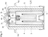
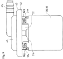
- the valve device (a second example) shown in Fig. 9 to Fig. 13 is attached to an upper portion of a fuel tank T.
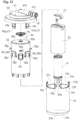
- the valve device comprises an outside member 40 having a size of blocking an attachment hole Ta formed on the upper portion of the fuel tank T; and a case 30 which can be inserted into the fuel tank T through the attachment hole Ta, and in a state wherein such case 30 is inserted into the fuel tank T, an outer peripheral portion of the outside member 40 is fixed on an outer face of the upper portion of the fuel tank T by welding and the like so as to be provided in the fuel tank T ( Fig. 11 ).
- Such valve device comprises the float valve 2, the case 30 housing the float valve 2, and the outside member 40 housing an upper portion side of the case 30.
- Such float valve 2, case 30, and outside member 40 are typically made of plastic.
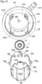
- the case 30 is formed by an outside cylinder member 31, and an inside cylinder member 32 combined with the outside cylinder member 31 by forming a gap S between the inside cylinder member 32 and the outside cylinder member 31.
- the outside cylinder member 31 includes a bottom portion 31a, and a circular through hole 31b at a center of the bottom portion 31a, and substantially has a cylindrical shape wherein an upper end is open (see Fig. 12 ).
- an upper end portion of the outside cylinder member 31 there is formed a plurality of concave notch portions 31c, 31c ... with intervals in a direction of surrounding a cylinder shaft of the outside cylinder member 31, and the upper end portion of the outside cylinder member 31 has a crown shape.
- an engagement window 31e In a projecting-piece-like portion 31d remaining between adjacent concave notch portions 31c and 31c of the outside cylinder member 31, there is formed an engagement window 31e.
- the inside cylinder member 32 includes a top portion 32a and a circular first through hole 32b at a center of the top portion 32a, and substantially has a cylindrical shape wherein a lower end is open (see Fig. 12 ).
- engaged portions 32c relative to engagement portions 41d of the outside member 40, penetration portions 32f, and engagement projections 32g relative to the engagement windows 31e of the outside cylinder member 31.
- each engaged portion 32c is provided with an interval between adjacent engaged portions 32c in a direction of surrounding a cylinder shaft of the inside cylinder member 32.
- a lower end is integrally connected to an outer face of the inside cylinder member 32, and the engaged portion 32c respectively comprises a pair of arm portions 32d and 32d extending upward with a gap between the pair of arm portions 32d and 32d and the outer face of the inside cylinder member 32; and bridge portions 32e ranging between upper ends of the pair of arm portions 32d and 32d.
- the penetration portions 32f are a square-shaped hole penetrating inside and outside of the inside cylinder member 32, and respectively formed between the adjacent engaged portions 32c and 32c.
- the engagement projections 32g project from the outer face of the inside cylinder member 32, and are respectively provided directly above the penetration portions 32f.
- the outside member 40 comprises a short cylindrical portion 41 wherein an upper end is closed and a lower end is open; and a flange portion 42 projecting outward from the lower end of the short cylindrical portion 41 (see Fig. 12 ).
- the short cylindrical portion 41 includes the upper end, i.e. a top portion 41a, and a circular second through hole 41b at a center of the top portion 41a (see Fig. 11 ).
- Such second through hole 41b extends horizontally by integrally connecting a pipe one end to a center of the top portion 41b on an upper face side of the top portion 41b of the outside member 40, and a pipe other end communicates to the outside of the tank through an exhaust port 41c having a pipe shape which is a connection portion to one end of a pipe member P forming one portion of the ventilation flow channel 1.
- the engagement portions 41d formed by elastic pieces 41e projecting downward by integrally connecting the upper end to the lower end of the short cylindrical portion 41, and projections 41f formed on a lower end outer side of the elastic pieces 41e.
- four engagement portions 41d are provided corresponding to the engaged portions 32c with an interval between adjacent engagement portions 41d in a direction of surrounding a cylinder shaft of the short cylindrical portion 41 of the outside member 40.
- the outside cylinder member 31 and the inside cylinder member 32 are combined such that the inside cylinder member 32 is inserted into the outside cylinder member 31 from an upper end side of the outside cylinder member 31 with the lower end of the inside cylinder member 32 foremost up to a position wherein the lower end of the inside cylinder member 32 hits the bottom portion 31a of the outside cylinder member 31.
- each projecting-piece-like portion 31d respectively abuts against the corresponding engagement projection 32g positioned directly above the penetration portion 32f positioned between the adjacent engaged portions 32c and 32c so as to elastically deform outward, and at a position wherein the inside cylinder member 32 is completely inserted, the projecting-piece-like portion 31d elastically returns to receive the engagement projection 32g into the engagement window 31e to be engaged.
- the gap S in such a way as to surround a cylinder shaft of the case 30. Also, an upper end portion 31f (a level of a base portion of the projecting-piece-like portion 31d) of the outside cylinder member 31 is positioned below an upper end of the inside cylinder member 32 and above the penetration portion 32f. Therewith, the gap S and an outside of the case 30 are communicated as an open end of the upper end portion 31f of the outside cylinder member 31.
- the case 30 and the outside member 40 formed as above are combined in such a way as to pinch one portion of the cylindrical seal member 7 fitted in the first through hole 32b to communicate the inner portion to the second through hole 41b, between the top portion 32a of the inside cylinder member 32 forming the case 30 wherein the first through hole 32b is formed, and the top portion 41a of the outside member 40 wherein the second through hole 41b is formed.
- the cylindrical seal member 7 is made of rubber or plastic having the rubber-like elasticity as with the first example.
- such cylindrical seal member 7 includes the outer flange portion 7a having the circular shape at the cylinder upper end (see Fig. 12 ).
- On the upper face of the outer flange portion 7a there is formed the circular projecting piece 7b.
- the outer diameter of the outer flange portion 7a is larger than a hole diameter of the first through hole 32b.
- the circular rising portion 7c in the outer peripheral portion of the cylindrical seal member 7, and in the position of the approximately middle in the up-and-down direction thereof, there is formed the circular rising portion 7c (see Fig. 13 ).
- the cylindrical seal member 7 is fitted in the first through hole 32b from above with the cylinder lower end side thereof foremost. At a completely fitted position, the outer flange portion 7a of the cylindrical seal member 7 contacts an outer face of the top portion 32a of the inside cylinder member 32 forming the case 30, and the circular rising portion 7c contacts an inner face of the top portion 32a of such inside cylinder member 32.
- the second through hole 41b is positioned directly above the upper end of the cylindrical seal member 7, and the outer flange portion 7a of the cylindrical seal member 7 is pinched by the outer face of the top portion 32a of the inside cylinder member 32 forming the case 30, and a portion which is an inner face of the top portion 41a of the outside member 40 and surrounds the second through hole 41b.
- one portion of the cylindrical seal member 7 pinched between the case 30 and the outside member 40 becomes the outer flange portion 7a.
- a pinched state of one portion of such cylindrical seal member 7, i.e. a combined state of the case 30 and the outside member 40, is maintained by engaging the engagement portion 41d with the engaged portion 32c.
- the projection 41f abuts against the bridge portion 32e of the engaged portion 32c, and the elastic piece 41e and the arm portion 32d elastically deform to allow the case 30 to enter into the outside member 40, and when the case 30 is completely entered into the outside member 40, the projection 41f enters below the bridge portion 32e, and the elastic piece 41e and the arm portion 32d elastically return so that the projection 41f is caught on the bridge portion 32e.
- the combined state of the case 30 and the outside member 40 is maintained (see Fig. 11 ).
- the float valve 2 and the spring 6 of the second example substantially have the structure same as the float valve 2 and the spring 6 of the first example, and prior to assemble the outside cylinder member 31 and the inside cylinder member 32 as mentioned above, the float valve 2 and the spring 6 of the second example are housed inside the inside cylinder member 32.
- the symbols same as the float valve 2 and the spring 6 in the drawings showing the first example are assigned to the float valve 2 and the spring 6 in the drawings showing the second example, and their explanations are omitted.
- the case 30 wherein the float valve 2 and the spring 6 are housed is combined with the outside member 40 to form the valve device.
- the lower end of the cylindrical seal member 7 protruding downward from the inner face of the top portion 32a of the inside cylinder member 32 forming the case 3 becomes the valve seat 7e of the float valve 2.
- the inside and outside of the tank can communicate through the open end (the upper end portion 31f of the outside cylinder member 31) of the gap S, the penetration portion 32f of the inside cylinder member 32, the cylindrical seal member 7, the second through hole 41b, and the exhaust port 41c.
- the open end (the upper end portion 31f of the outside cylinder member 31) is positioned above the penetration portion 32f of the inside cylinder member 32, and the penetration portion 32f of the inside cylinder member 32 is formed in the side portion of the inside cylinder member 32, so that a flow channel through such open end (the upper end portion 31f of the outside cylinder member 31), the gap S, and the penetration portion 32f meanders up and down so as to prevent the outflow of the fuel to the outside of the tank in the state before the float valve 2 sits onto the valve seat 7e as much as possible.
- the cylindrical seal member 7 can seal between the top portion 41a of the outside member 40 and the cylindrical seal member 7, and between the cylindrical seal member 7 and the top portion 32a of the inside cylinder member 32 forming the case 30 in the airtight state.
- the outer flange portion 7a of the cylindrical seal member 7 is pressed against a hole edge portion of the second through hole 41b of the top portion 41a of the outside member 40 and a hole edge portion of the first through hole 32b of the top portion 32a of the inside cylinder member 32 forming the case 30, and the ventilation between the valve device and the outside of the tank is carried out only through the inner portion of the cylindrical seal member 7.
- the cylindrical seal member 7 serves as the valve seat 7e of the float valve 2 as well.
- the parts comprising the seal function can be formed by one cylindrical seal member 7 so as to minimize the number of the component parts of this kind of valve device, and further reduce costs.
Landscapes
- Engineering & Computer Science (AREA)
- General Engineering & Computer Science (AREA)
- Mechanical Engineering (AREA)
- Chemical & Material Sciences (AREA)
- Combustion & Propulsion (AREA)
- Sustainable Development (AREA)
- Life Sciences & Earth Sciences (AREA)
- Sustainable Energy (AREA)
- Transportation (AREA)
- Cooling, Air Intake And Gas Exhaust, And Fuel Tank Arrangements In Propulsion Units (AREA)
- Self-Closing Valves And Venting Or Aerating Valves (AREA)
- Float Valves (AREA)
- Valve Housings (AREA)
Applications Claiming Priority (3)
| Application Number | Priority Date | Filing Date | Title |
|---|---|---|---|
| JP2014097413 | 2014-05-09 | ||
| JP2015006043A JP6203205B2 (ja) | 2014-05-09 | 2015-01-15 | 弁装置 |
| PCT/JP2015/062584 WO2015170621A1 (ja) | 2014-05-09 | 2015-04-24 | 弁装置 |
Publications (3)
| Publication Number | Publication Date |
|---|---|
| EP3141785A1 EP3141785A1 (en) | 2017-03-15 |
| EP3141785A4 EP3141785A4 (en) | 2018-01-03 |
| EP3141785B1 true EP3141785B1 (en) | 2024-07-17 |
Family
ID=54392474
Family Applications (1)
| Application Number | Title | Priority Date | Filing Date |
|---|---|---|---|
| EP15789602.8A Active EP3141785B1 (en) | 2014-05-09 | 2015-04-24 | Valve device |
Country Status (5)
| Country | Link |
|---|---|
| US (1) | US10113514B2 (ko) |
| EP (1) | EP3141785B1 (ko) |
| JP (1) | JP6203205B2 (ko) |
| CN (1) | CN106415095B (ko) |
| WO (1) | WO2015170621A1 (ko) |
Families Citing this family (7)
| Publication number | Priority date | Publication date | Assignee | Title |
|---|---|---|---|---|
| USD899458S1 (en) * | 2017-02-16 | 2020-10-20 | Eaton Corporation | Fill limit venting valve with high shut-off height |
| JP6908469B2 (ja) * | 2017-08-24 | 2021-07-28 | 株式会社パイオラックス | 弁装置 |
| JP7019515B2 (ja) | 2018-06-06 | 2022-02-15 | 愛三工業株式会社 | 流体制御弁 |
| WO2020144089A1 (en) * | 2019-01-11 | 2020-07-16 | Eaton Intelligent Power Limited | Flapper assembly, a valve assembly that utilizes the flapper assembly, and a method of forming the flapper assembly |
| WO2020164805A1 (en) * | 2019-02-11 | 2020-08-20 | Eaton Intelligent Power Limited | Pressure relief assembly and a valve assembly that uses the pressure relief assembly |
| WO2020164806A1 (en) * | 2019-02-13 | 2020-08-20 | Eaton Intelligent Power Limited | Multi-material orifice plates for vent valve assemblies of liquid containment systems |
| GB2610754A (en) * | 2020-06-15 | 2023-03-15 | Piolax Inc | Valve device |
Citations (1)
| Publication number | Priority date | Publication date | Assignee | Title |
|---|---|---|---|---|
| US20020017281A1 (en) * | 1999-04-28 | 2002-02-14 | Crary Lynwood F. | Vent and rollover valve and fuel pump module |
Family Cites Families (18)
| Publication number | Priority date | Publication date | Assignee | Title |
|---|---|---|---|---|
| JPH0439061Y2 (ko) * | 1986-11-27 | 1992-09-11 | ||
| US4886089A (en) * | 1988-05-27 | 1989-12-12 | Gt Development Corporation | Gas venting valve for liquid tank |
| US5090459A (en) * | 1990-01-29 | 1992-02-25 | Toyoda Gosei Co., Ltd. | Fuel tank system |
| JPH07257205A (ja) * | 1994-03-28 | 1995-10-09 | Toyoda Gosei Co Ltd | 燃料タンク用フロートバルブ |
| JP3131763B2 (ja) | 1995-09-08 | 2001-02-05 | 京三電機株式会社 | 止め弁の構造 |
| US5975116A (en) * | 1996-08-07 | 1999-11-02 | Borg-Warner Automotive, Inc. | Valve having multi-piece valve housing |
| US5960816A (en) * | 1997-03-26 | 1999-10-05 | G.T. Products, Inc. | Adjustable length vent valve system for fuel tanks |
| JP3374120B2 (ja) * | 2000-05-19 | 2003-02-04 | 本田技研工業株式会社 | 燃料タンクのバルブ取付構造 |
| US6578597B2 (en) | 2001-03-08 | 2003-06-17 | Stant Manufacturing Inc. | Fuel tank vent system with liquid fuel filter |
| JP2002021667A (ja) * | 2001-05-15 | 2002-01-23 | Nifco Inc | 燃料タンクの液面検知バルブ |
| JP4317397B2 (ja) * | 2003-07-10 | 2009-08-19 | 株式会社パイオラックス | フロート弁装置の製造方法 |
| US6918405B2 (en) * | 2003-12-04 | 2005-07-19 | Alfmeier Corporation | Fill limit vent valve |
| US20060000091A1 (en) | 2004-07-02 | 2006-01-05 | Eaton Corporation | Rapid response fuel tank rollover/vent valve |
| JP4742994B2 (ja) * | 2005-09-28 | 2011-08-10 | 豊田合成株式会社 | 燃料遮断弁 |
| JP4939120B2 (ja) * | 2006-06-16 | 2012-05-23 | 株式会社パイオラックス | 液体遮断弁装置 |
| US8186372B2 (en) * | 2007-03-30 | 2012-05-29 | Toyoda Gosei Co., Ltd. | Fuel shut-off valve |
| JP2010188991A (ja) * | 2009-01-23 | 2010-09-02 | Yachiyo Industry Co Ltd | 通気規制弁装置 |
| JP5437784B2 (ja) | 2009-12-17 | 2014-03-12 | 株式会社ニフコ | 燃料タンク用弁装置 |
-
2015
- 2015-01-15 JP JP2015006043A patent/JP6203205B2/ja not_active Expired - Fee Related
- 2015-04-24 WO PCT/JP2015/062584 patent/WO2015170621A1/ja active Application Filing
- 2015-04-24 CN CN201580028959.9A patent/CN106415095B/zh active Active
- 2015-04-24 US US15/309,841 patent/US10113514B2/en active Active
- 2015-04-24 EP EP15789602.8A patent/EP3141785B1/en active Active
Patent Citations (1)
| Publication number | Priority date | Publication date | Assignee | Title |
|---|---|---|---|---|
| US20020017281A1 (en) * | 1999-04-28 | 2002-02-14 | Crary Lynwood F. | Vent and rollover valve and fuel pump module |
Also Published As
| Publication number | Publication date |
|---|---|
| JP2015227723A (ja) | 2015-12-17 |
| CN106415095B (zh) | 2019-08-13 |
| US10113514B2 (en) | 2018-10-30 |
| CN106415095A (zh) | 2017-02-15 |
| JP6203205B2 (ja) | 2017-09-27 |
| US20170138316A1 (en) | 2017-05-18 |
| WO2015170621A1 (ja) | 2015-11-12 |
| EP3141785A1 (en) | 2017-03-15 |
| EP3141785A4 (en) | 2018-01-03 |
Similar Documents
| Publication | Publication Date | Title |
|---|---|---|
| EP3141785B1 (en) | Valve device | |
| EP3276154B1 (en) | Valve device | |
| JP6203296B2 (ja) | 弁装置 | |
| US8365756B2 (en) | Fuel tank valve device | |
| JP5242440B2 (ja) | 燃料タンク用弁装置及び燃料タンク用過給油防止装置 | |
| EP3141784B1 (en) | Valve device | |
| RU2015120579A (ru) | Емкость и клапан для емкости | |
| JP6200097B2 (ja) | 弁ケースの取付構造 | |
| RU2015120583A (ru) | Емкость для напитков и клапан для емкости для напитков | |
| US8616232B2 (en) | Fuel cut-off valve | |
| WO2015122407A1 (ja) | 弁装置 | |
| JP2006290085A (ja) | フロートバルブのシール構造 | |
| JP2006144756A (ja) | 燃料タンクのポンプモジュール構造 | |
| CN112648118B (zh) | 燃料箱用阀装置 | |
| CN103591339A (zh) | 止回阀 | |
| US10738909B2 (en) | Fuel tank valve | |
| JP5876731B2 (ja) | 燃料タンク用コネクタ | |
| JP5013422B2 (ja) | 液体噴出ポンプ | |
| KR20130002719U (ko) | 솔레노이드를 이용한 밸브 구조체 | |
| KR20150108585A (ko) | 커넥터 |
Legal Events
| Date | Code | Title | Description |
|---|---|---|---|
| STAA | Information on the status of an ep patent application or granted ep patent |
Free format text: STATUS: THE INTERNATIONAL PUBLICATION HAS BEEN MADE |
|
| PUAI | Public reference made under article 153(3) epc to a published international application that has entered the european phase |
Free format text: ORIGINAL CODE: 0009012 |
|
| STAA | Information on the status of an ep patent application or granted ep patent |
Free format text: STATUS: REQUEST FOR EXAMINATION WAS MADE |
|
| 17P | Request for examination filed |
Effective date: 20161121 |
|
| AK | Designated contracting states |
Kind code of ref document: A1 Designated state(s): AL AT BE BG CH CY CZ DE DK EE ES FI FR GB GR HR HU IE IS IT LI LT LU LV MC MK MT NL NO PL PT RO RS SE SI SK SM TR |
|
| AX | Request for extension of the european patent |
Extension state: BA ME |
|
| DAV | Request for validation of the european patent (deleted) | ||
| DAX | Request for extension of the european patent (deleted) | ||
| A4 | Supplementary search report drawn up and despatched |
Effective date: 20171205 |
|
| RIC1 | Information provided on ipc code assigned before grant |
Ipc: F02M 37/00 20060101ALI20171129BHEP Ipc: F16K 31/18 20060101ALI20171129BHEP Ipc: F02M 37/20 20060101ALI20171129BHEP Ipc: B60K 15/035 20060101ALI20171129BHEP Ipc: F02M 25/08 20060101ALI20171129BHEP Ipc: F16K 24/04 20060101ALI20171129BHEP Ipc: F16K 24/00 20060101AFI20171129BHEP |
|
| STAA | Information on the status of an ep patent application or granted ep patent |
Free format text: STATUS: EXAMINATION IS IN PROGRESS |
|
| STAA | Information on the status of an ep patent application or granted ep patent |
Free format text: STATUS: EXAMINATION IS IN PROGRESS |
|
| 17Q | First examination report despatched |
Effective date: 20210119 |
|
| STAA | Information on the status of an ep patent application or granted ep patent |
Free format text: STATUS: EXAMINATION IS IN PROGRESS |
|
| GRAP | Despatch of communication of intention to grant a patent |
Free format text: ORIGINAL CODE: EPIDOSNIGR1 |
|
| STAA | Information on the status of an ep patent application or granted ep patent |
Free format text: STATUS: GRANT OF PATENT IS INTENDED |
|
| INTG | Intention to grant announced |
Effective date: 20240320 |
|
| GRAS | Grant fee paid |
Free format text: ORIGINAL CODE: EPIDOSNIGR3 |
|
| GRAA | (expected) grant |
Free format text: ORIGINAL CODE: 0009210 |
|
| STAA | Information on the status of an ep patent application or granted ep patent |
Free format text: STATUS: THE PATENT HAS BEEN GRANTED |
|
| AK | Designated contracting states |
Kind code of ref document: B1 Designated state(s): AL AT BE BG CH CY CZ DE DK EE ES FI FR GB GR HR HU IE IS IT LI LT LU LV MC MK MT NL NO PL PT RO RS SE SI SK SM TR |
|
| REG | Reference to a national code |
Ref country code: GB Ref legal event code: FG4D |
|
| REG | Reference to a national code |
Ref country code: CH Ref legal event code: EP |
|
| REG | Reference to a national code |
Ref country code: DE Ref legal event code: R096 Ref document number: 602015089241 Country of ref document: DE |
|
| REG | Reference to a national code |
Ref country code: IE Ref legal event code: FG4D |