EP3141712A1 - Verfahren zum betreiben eines ölkreislaufs, insbesondere für ein fahrzeug - Google Patents
Verfahren zum betreiben eines ölkreislaufs, insbesondere für ein fahrzeug Download PDFInfo
- Publication number
- EP3141712A1 EP3141712A1 EP16001936.0A EP16001936A EP3141712A1 EP 3141712 A1 EP3141712 A1 EP 3141712A1 EP 16001936 A EP16001936 A EP 16001936A EP 3141712 A1 EP3141712 A1 EP 3141712A1
- Authority
- EP
- European Patent Office
- Prior art keywords
- oil
- temperature
- internal combustion
- combustion engine
- oil circuit
- Prior art date
- Legal status (The legal status is an assumption and is not a legal conclusion. Google has not performed a legal analysis and makes no representation as to the accuracy of the status listed.)
- Granted
Links
Images


Classifications
-
- F—MECHANICAL ENGINEERING; LIGHTING; HEATING; WEAPONS; BLASTING
- F01—MACHINES OR ENGINES IN GENERAL; ENGINE PLANTS IN GENERAL; STEAM ENGINES
- F01P—COOLING OF MACHINES OR ENGINES IN GENERAL; COOLING OF INTERNAL-COMBUSTION ENGINES
- F01P7/00—Controlling of coolant flow
- F01P7/14—Controlling of coolant flow the coolant being liquid
- F01P7/16—Controlling of coolant flow the coolant being liquid by thermostatic control
- F01P7/167—Controlling of coolant flow the coolant being liquid by thermostatic control by adjusting the pre-set temperature according to engine parameters, e.g. engine load, engine speed
-
- F—MECHANICAL ENGINEERING; LIGHTING; HEATING; WEAPONS; BLASTING
- F01—MACHINES OR ENGINES IN GENERAL; ENGINE PLANTS IN GENERAL; STEAM ENGINES
- F01M—LUBRICATING OF MACHINES OR ENGINES IN GENERAL; LUBRICATING INTERNAL COMBUSTION ENGINES; CRANKCASE VENTILATING
- F01M5/00—Heating, cooling, or controlling temperature of lubricant; Lubrication means facilitating engine starting
- F01M5/002—Cooling
-
- F—MECHANICAL ENGINEERING; LIGHTING; HEATING; WEAPONS; BLASTING
- F01—MACHINES OR ENGINES IN GENERAL; ENGINE PLANTS IN GENERAL; STEAM ENGINES
- F01M—LUBRICATING OF MACHINES OR ENGINES IN GENERAL; LUBRICATING INTERNAL COMBUSTION ENGINES; CRANKCASE VENTILATING
- F01M5/00—Heating, cooling, or controlling temperature of lubricant; Lubrication means facilitating engine starting
- F01M5/005—Controlling temperature of lubricant
-
- F—MECHANICAL ENGINEERING; LIGHTING; HEATING; WEAPONS; BLASTING
- F01—MACHINES OR ENGINES IN GENERAL; ENGINE PLANTS IN GENERAL; STEAM ENGINES
- F01P—COOLING OF MACHINES OR ENGINES IN GENERAL; COOLING OF INTERNAL-COMBUSTION ENGINES
- F01P11/00—Component parts, details, or accessories not provided for in, or of interest apart from, groups F01P1/00 - F01P9/00
- F01P11/08—Arrangements of lubricant coolers
-
- F—MECHANICAL ENGINEERING; LIGHTING; HEATING; WEAPONS; BLASTING
- F01—MACHINES OR ENGINES IN GENERAL; ENGINE PLANTS IN GENERAL; STEAM ENGINES
- F01P—COOLING OF MACHINES OR ENGINES IN GENERAL; COOLING OF INTERNAL-COMBUSTION ENGINES
- F01P7/00—Controlling of coolant flow
- F01P7/14—Controlling of coolant flow the coolant being liquid
-
- F—MECHANICAL ENGINEERING; LIGHTING; HEATING; WEAPONS; BLASTING
- F01—MACHINES OR ENGINES IN GENERAL; ENGINE PLANTS IN GENERAL; STEAM ENGINES
- F01M—LUBRICATING OF MACHINES OR ENGINES IN GENERAL; LUBRICATING INTERNAL COMBUSTION ENGINES; CRANKCASE VENTILATING
- F01M5/00—Heating, cooling, or controlling temperature of lubricant; Lubrication means facilitating engine starting
- F01M5/002—Cooling
- F01M2005/004—Oil-cooled engines
-
- F—MECHANICAL ENGINEERING; LIGHTING; HEATING; WEAPONS; BLASTING
- F01—MACHINES OR ENGINES IN GENERAL; ENGINE PLANTS IN GENERAL; STEAM ENGINES
- F01M—LUBRICATING OF MACHINES OR ENGINES IN GENERAL; LUBRICATING INTERNAL COMBUSTION ENGINES; CRANKCASE VENTILATING
- F01M2250/00—Measuring
- F01M2250/60—Operating parameters
-
- F—MECHANICAL ENGINEERING; LIGHTING; HEATING; WEAPONS; BLASTING
- F01—MACHINES OR ENGINES IN GENERAL; ENGINE PLANTS IN GENERAL; STEAM ENGINES
- F01M—LUBRICATING OF MACHINES OR ENGINES IN GENERAL; LUBRICATING INTERNAL COMBUSTION ENGINES; CRANKCASE VENTILATING
- F01M2250/00—Measuring
- F01M2250/62—Load
-
- F—MECHANICAL ENGINEERING; LIGHTING; HEATING; WEAPONS; BLASTING
- F01—MACHINES OR ENGINES IN GENERAL; ENGINE PLANTS IN GENERAL; STEAM ENGINES
- F01P—COOLING OF MACHINES OR ENGINES IN GENERAL; COOLING OF INTERNAL-COMBUSTION ENGINES
- F01P2025/00—Measuring
- F01P2025/08—Temperature
- F01P2025/40—Oil temperature
-
- F—MECHANICAL ENGINEERING; LIGHTING; HEATING; WEAPONS; BLASTING
- F01—MACHINES OR ENGINES IN GENERAL; ENGINE PLANTS IN GENERAL; STEAM ENGINES
- F01P—COOLING OF MACHINES OR ENGINES IN GENERAL; COOLING OF INTERNAL-COMBUSTION ENGINES
- F01P2025/00—Measuring
- F01P2025/60—Operating parameters
-
- F—MECHANICAL ENGINEERING; LIGHTING; HEATING; WEAPONS; BLASTING
- F01—MACHINES OR ENGINES IN GENERAL; ENGINE PLANTS IN GENERAL; STEAM ENGINES
- F01P—COOLING OF MACHINES OR ENGINES IN GENERAL; COOLING OF INTERNAL-COMBUSTION ENGINES
- F01P2025/00—Measuring
- F01P2025/60—Operating parameters
- F01P2025/64—Number of revolutions
Definitions
- the invention relates to a method for operating an oil circuit, in particular for a vehicle, according to the preamble of patent claim 1, a device for a vehicle, in particular for a commercial vehicle, according to the preamble of claim 14 and a vehicle, in particular a commercial vehicle, for carrying out the Method and / or with the device according to claim 15.
- An internal combustion engine is usually supplied with oil by means of an oil circuit.
- the oil can be used both for lubrication of the internal combustion engine and for cooling the internal combustion engine.
- Such an oil circuit regularly has at least one oil cooler, by means of which the oil flowing through the oil circuit is cooled.
- This oil cooler is often designed as a heat-absorbing heat exchanger of a coolant circuit, by means of which both the internal combustion engine and the oil flowing through the oil circuit can be cooled.
- the oil circuit usually also has at least one temperature sensor, by means of which the temperature of the oil flowing through the oil circuit, as seen in the oil flow direction, is measured downstream of the oil cooler and upstream of the internal combustion engine. By means of this temperature sensor can be checked or checked whether the oil flowing through the oil circuit has the desired temperature or not.
- the oil circuit is usually designed such that the oil flowing through the oil circuit has an operating temperature of 85 to 100 ° C. in the region of the temperature sensor over a wide range of engine operating points. By such an operating temperature of the oil prevents the oil, especially at full load of the internal combustion engine, heated so much that it is damaged or there is a high mixed friction.
- the object of the invention is to provide a method for operating an oil circuit, in particular for a vehicle, and a device for a vehicle, in particular for a commercial vehicle, by means of which the fuel consumption of the internal combustion engine can be reduced in a simple and effective manner.
- a method for operating an oil circuit, in particular for a vehicle proposed, by means of the oil circuit, an internal combustion engine is supplied with oil, said oil circuit having at least one oil cooler, by means of which the oil flowing through the oil circuit is cooled, and wherein at least one temperature sensor is provided, by means of which the temperature of the oil flowing through the oil circuit, in particular downstream of the oil cooler and upstream of the internal combustion engine, is measured.
- the temperature sensor is signal-wise connected to a regulating and / or control device, by means of which the temperature of the oil flowing through the oil circuit is controlled and / or regulated, such that the temperature measured by means of the temperature sensor has a defined temperature setpoint.
- the temperature setpoint as a function of the drive power, in particular as a function of the drive torque and / or as a function of the drive speed, the internal combustion engine adjusted by the control and / or control device and / or adjusted.
- the fuel consumption of the internal combustion engine can be reduced simply and effectively, since the temperature of the oil flowing through the oil circuit in the region of the temperature sensor is now adjusted or adjusted in dependence on the drive power of the internal combustion engine by means of the control and / or control device.
- a larger temperature setpoint can be set at a smaller drive power of the internal combustion engine.
- the viscosity of the oil and thus the fuel consumption of the internal combustion engine is reduced. Due to the low drive power of the internal combustion engine, the oil is also not so much heated in the engine that it is damaged.
- a smaller temperature setpoint can be adjusted or adjusted by means of the control and / or control device.
- the temperature of the oil flowing through the oil circuit can thus always be set in such a way that the internal combustion engine has a minimum fuel consumption. As a result, the pollutants emitted by the internal combustion engine can also be reduced.
- the term "temperature sensor” is here to be understood in a broad sense.
- the temperature sensor can be formed here by any temperature detecting means by which detects the temperature of the oil flowing through the oil circuit can be.
- the temperature of the oil is measured by means of a temperature sensor, for example by means of a thermocouple.
- a first temperature value is set as the temperature setpoint. If the drive power of the internal combustion engine does not exceed the defined drive power value, a second temperature value formed larger than the first temperature value can then be set as the temperature setpoint value. In this way, the fuel consumption of the internal combustion engine can be easily and effectively reduced.
- at least one characteristic map is preferably stored in the regulating and / or control device into which the temperature set value is entered as a function of the drive power of the internal combustion engine.
- a temperature setpoint is reliably ensured that the oil flowing through the oil circuit in full load operation and / or in the upper part load range of the internal combustion engine is not heated too much by the internal combustion engine.
- a temperature value of 105 ° C to 120 ° C preferably set from 110 ° C to 120 ° C as a defined temperature setpoint.
- the oil circuit has at least one bypass channel, by means of which at least part of the oil flowing through the oil circuit can be conducted past the oil cooler, wherein the control and / or control device for controlling or regulating the oil temperature has an adjusting device, by means of which the amount of oil flowing through the bypass passage and the amount of oil passed through the oil cooler can be adjusted and / or adjusted.
- the temperature of the oil flowing through the oil circuit can be adjusted or adjusted in a particularly simple and effective manner by means of the regulating and / or control device become.
- the fuel consumption of the internal combustion engine can be reduced particularly effectively.
- the temperature of the oil flowing through the oil circuit is measured downstream of an oil outlet of the bypass channel and upstream of the internal combustion engine.
- the adjusting device is formed by at least one valve. It is preferably provided that the valve is formed by a controlled and / or controlled valve, in particular by a controlled and / or controlled directional control valve, to adjust the temperature of the oil flowing through the oil circuit in a particularly flexible manner or always as desired can.
- a coolant circuit is provided, by means of which the internal combustion engine and the oil cooler or the oil circuit can be cooled by means of a coolant, wherein at a cold start of the internal combustion engine, the entire oil is passed through the oil cooler.
- the oil flowing through the oil circuit can be heated particularly quickly in a cold start, since the coolant flowing through the coolant circuit is heated faster during a cold start than the oil flowing through the oil circuit.
- the oil temperature is below a defined temperature value, preferably below 10 ° C
- the entire oil can be passed through the bypass channel. This effectively counteracts damage to the oil cooler by the particularly viscous or highly viscous oil at low temperatures and the resulting high oil pressure.
- the oil circuit at least a regulated oil pump, by means of which the oil is conveyed through the oil circuit, wherein the oil pump and thus the amount of oil delivered by the oil pump for controlling the temperature of the oil flowing through the oil circuit controlled by the control and / or control device and / or controlled.
- the temperature of the oil flowing through the oil circuit can also be adjusted and adjusted simply and effectively by means of the regulating and / or control device.
- a coolant circuit is provided, by means of which the internal combustion engine and the oil cooler or the oil circuit are cooled by means of a coolant, wherein at least one of the cooling of the oil cooler and the oil circuit influencing component of the coolant circuit for controlling the temperature of the flowing through the oil circuit Oil is regulated and / or controlled by means of the control and / or control device.
- the temperature of the oil flowing through the oil circuit can also be adjusted or adjusted simply and effectively by means of the regulating and / or control device.
- the at least one component of the coolant circuit is formed by a fan for cooling a heat dissipating heat exchanger of the coolant circuit and / or by a regulated coolant pump and / or by a controlled thermostatic valve.
- the regulating and / or control device is signal-wise connected to a prognostic device by means of which the anticipated drive power, in particular the anticipated drive torque and / or the anticipated drive speed, of the internal combustion engine can be determined on a preceding route section of a vehicle having the drive device , Wherein the temperature setpoint, seen in terms of time, is already set or adjusted by means of the regulating and / or control device before reaching the preceding route section as a function of the anticipated drive power of the internal combustion engine determined by means of the prognostic device.
- the temperature of the oil flowing through the oil circuit can, in terms of time, already be adjusted or adjusted in such a way by means of the regulating and / or control device before the reaching of the preceding route section that the temperature of the oil flowing through the oil circuit is reached when reaching or Driving through the route section lying ahead has the optimum temperature for driving through the road section lying ahead.
- the temperature setpoint seen in terms of time, can already be reduced in front of a preceding route section, at which a particularly high drive power of the internal combustion engine is required.
- a preceding route section for example, be a longer slope of the route.
- the temperature setpoint, seen in terms of time can already be increased in front of a preceding route section on which a particularly low drive power of the internal combustion engine is required.
- Such a preceding route section may for example be a longer slope.
- the prognostic device has a weight determination, by means of which the weight of the vehicle can be determined.
- weight-determining means can be reliably and easily determined the driving power of the vehicle required on the preceding route section.
- the prognostic device has a slope determination device, by means of which the gradient of the preceding route section can be determined. In this way, the drive power required at the preceding route section can likewise be determined simply and reliably by means of the prognostic device.
- the gradient of the route section lying ahead can be determined, for example, by determining the position of the vehicle on its route, for example via GPS, in conjunction with gradient data from a digital road map.
- the temperature setpoint is additionally set and / or adjusted in dependence on the current viscosity of the oil by means of the control and / or control device in order to adjust the temperature setpoint optimally.
- at least one characteristic map is preferably stored in the regulating and / or control device into which the temperature set value is entered as a function of the drive power and the viscosity of the oil.
- a viscosity-measuring device connected to the regulating and / or control device is provided, by means of which the current viscosity of the oil flowing through the oil circuit can be measured.
- a viscosity measuring device By means of such a viscosity measuring device, the current viscosity of the oil can always be determined reliably and with high accuracy. It is preferably provided that the viscosity of the oil flowing through the oil circuit downstream of an oil pan of the oil circuit and upstream of the oil cooler is measured by means of the viscosity measuring device.
- a signal-technically connected to the control and / or control device is provided, actuatable by a person input device by means of the viscosity class and / or the HTHS characteristic of the currently used oil, in particular manually entered can be.
- This information can be used to determine which oil type or which oil is currently being used.
- the information about the currently used oil can then be used to determine the current viscosity of the oil.
- the determination of the current viscosity of the oil can be done for example by means of a stored in the control and / or control device map, in which the viscosity of the oil used in dependence on the oil temperature is registered.
- the oil temperature can be measured for example by means of a temperature sensor. It is preferably provided that in the control and / or control device for such a type of oil such a map is stored.
- the viscosity class and / or the HTHS characteristic of the oil can be entered, for example, in an oil change in the input device.
- a signal technically connected to the control and / or control device pressure sensor is provided, by means of which the pressure of the oil flowing through the oil circuit lubricating oil is measured, the pressure sensor, seen in the oil flow direction, downstream of an oil outlet of the bypass channel and upstream of the Internal combustion engine is arranged in or on the oil circuit.
- a pressure sensor can be used for example for monitoring the internal combustion engine, for controlling an oil pump or for measuring the current viscosity of the oil.
- a transmission oil circuit is provided, by means of which, in particular with the internal combustion engine coupled, transmission can be supplied with oil, wherein the oil circuit or engine oil circuit and the transmission oil circuit are formed separately. More preferably, a single oil circuit for supplying the internal combustion engine with oil is provided.
- an actuatable by a person actuator in particular a button and / or a switch provided by means of an "Eco-Friction mode” can be activated and deactivated, wherein upon activation of the "Eco-friction mode", the internal combustion engine is no longer operated at full load and / or high part load. In this way, a higher temperature setpoint can be set in "eco-friction mode" and the fuel consumption of the internal combustion engine can be reduced.
- a device for a vehicle in particular for a commercial vehicle is further claimed, with an oil circuit, by means of which an internal combustion engine can be supplied with oil, wherein the oil circuit has at least one oil cooler, by means of which the oil flowing through the oil circuit can be cooled, and wherein at least one temperature sensor is provided, by means of which the temperature of the oil flowing through the oil circuit, in particular downstream of the oil cooler and upstream of the internal combustion engine, can be measured.
- the temperature sensor is signal-wise connected to a control and / or control device, by means of the temperature of the oil flowing through the oil circuit can be controlled and / or regulated, such that the temperature measured by means of the temperature sensor has a defined temperature setpoint.
- the temperature setpoint in particular for reducing the fuel consumption of the internal combustion engine, as a function of the drive power, in particular in dependence on the drive torque and / or in dependence on the input speed of the internal combustion engine, adjusted by means of the control and / or control device and / / or be adjusted.
- a vehicle in particular a commercial vehicle, for carrying out the method according to the invention and / or with the device according to the invention claimed.
- the resulting advantages are also identical to the already appreciated advantages of the process control according to the invention, so that these are not repeated here.
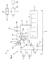
- Fig. 1 is a vehicle 1 exemplified here as a truck with a device according to the invention 3 ( Fig. 2 ).
- the structure of the device 3 based on the Fig. 2 explained in more detail:
- the device 3 an oil circuit 5, by means of a in Fig. 2 indicated by dashed lines engine 7 is supplied with oil 8.
- the oil circuit 5 has here, by way of example, seen in the oil flow direction, an oil pan 9, an oil pump 11, a directional control valve 13, an oil cooler 15 and a main channel 17.
- oil pump 11 accumulated in the oil pan 9 oil 8 is sucked and conveyed into the further oil circuit 5.
- the here exemplified trained as a 3/2-way valve directional control valve 13 forms an actuating device, by means of which the amount of oil passed through the oil cooler 15 8 and the amount of flowing through a bypass channel 19 of the oil circuit 5 oil 8 can be adjusted or adjusted.
- the oil circuit 5 branches off, for example, at a branching region 21 arranged upstream of the oil cooler 15 into the bypass channel 19 and into an oil cooler channel 23.
- a junction region 25 arranged downstream of the oil cooler 15, viewed in the oil flow direction the bypass channel 19 and the oil cooler channel join 23 again.
- the branching region 21 is formed here by way of example by the directional control valve 13. Downstream of the merging region 25, the main channel 17 of the oil circuit 5 runs here.
- the internal combustion engine 7, the oil pump 11 and the directional control valve 13 are also signal-wise connected to a control unit 35 by means of which the oil pump 11 and the directional control valve 13 are controlled.
- the device 3 here also has a pressure sensor 37, by means of which the pressure of the oil 8 flowing through the oil circuit 5 can be measured in or on the main channel 17 of the oil circuit 5.
- the device 3 has a temperature sensor 39, by means of which the temperature of the oil flowing through the oil circuit 5 6 in or on the main channel 17 of the oil circuit 5 can be measured.
- the pressure sensor 37 and the temperature sensor 39 are here also connected by signal technology with the control unit 35.
- the vehicle 1 a temperature sensor 27, by means of which the temperature of the accumulated in the oil pan 9 oil 8 of the oil circuit 5 can be measured.
- the device 3 also has a pressure sensor 31, by means of which the pressure of the oil 8 flowing through the oil circuit 5, viewed in the oil flow direction, can be measured downstream of the oil pump 11 and upstream of the directional control valve 13.
- the device here by way of example also has a volumetric flow sensor 33, by means of which the volume flow of the oil 8 flowing through the oil circuit 5, viewed in the oil flow direction, can be measured downstream of the oil pump 11 and upstream of the directional control valve 13.
- the temperature sensor 27, the pressure sensor 31 and the volume flow sensor 33 are signal-technically connected to the control unit 35.
- the temperature measured by means of the temperature sensor 27, the pressures measured by the pressure sensors 31, 37 and the volumetric flow rate measured by the volumetric flow sensor 33 can be used to control the current viscosity of the oil 8 flowing through the oil circuit 5, viewed in the direction of oil flow, downstream by means of the control unit 35 the internal combustion engine 7 and upstream of the directional valve 21 are calculated.
- the temperature sensor 27, the pressure sensors 31, 37, the volume flow sensor 33 and the control unit 35 thus form here a viscosity measuring device.
- the current viscosity of the oil 8 could also be calculated, for example, via the temperature measured by means of the temperature sensor 27, the pressures measured by means of the pressure sensors 31, 37 and the rotational speed of the internal combustion engine 7.
- the device 3 could also have a in Fig. 2 Indicated by dashed lines, actuatable by a person input device 36, by means of the viscosity class and / or the HTHS characteristic of the currently used oil 8 can be entered. Using this information, the current viscosity of the oil can also be determined.
- Fig. 2 further shows, the device 3 here by way of example also in Fig. 2 partially shown coolant circuit 41, by means of which the internal combustion engine 7 and the oil circuit 5 and the oil flowing through the oil circuit 5 8 can be cooled by means of a coolant.
- the coolant circuit 41 has here, by way of example, viewed in the coolant flow direction, a coolant pump 43, the oil cooler 15 as a heat-absorbing heat exchanger, and the internal combustion engine 7.
- the coolant pump 43 is likewise signal-wise connected to the control unit 35 and is controlled by means of the control unit 35 as a function of a coolant temperature measured by means of a temperature sensor 45.
- the temperature of the coolant flowing through the coolant circuit 41 downstream of the coolant delivery device 43 and upstream of the oil cooler 15 is measured by means of the temperature sensor 45.
- the directional control valve 13, the oil pump 15 and the coolant pump 43 are controlled or regulated by means of the control unit 35 such that the oil temperature measured by means of the temperature sensor 39 has a defined temperature setpoint.
- the temperature setpoint is exemplified here as a function of the drive power of the internal combustion engine 7 and determined by means of the control unit 35, the current viscosity of the oil 8 adjusted by means of the control unit 35 and / or adjusted.
- the temperature setpoint is here set by way of example in such a way of the control unit 35, which, provided that the drive power P A of the internal combustion engine 7 defines a defined drive power value P A, def . exceeds, a first temperature value T 1 is set as the temperature setpoint T soll . If the drive power P A of the internal combustion engine 7 the defined drive power value P A, def. does not exceed a value greater than the first temperature T 1 Trained, second temperature value T 2 is used as setpoint temperature T set is set by means of the control unit 35th In this way, the viscosity of the oil flowing through the oil circuit 5 8 is always kept as low as possible and thus reduces the fuel consumption of the engine 7.
- the device 3 here also has an optional prognostic device 47, by means of which the anticipated drive power of the internal combustion engine 7 can be determined on a route section of the vehicle 1 lying ahead.
- the temperature setpoint value can then be adjusted and / or adjusted here, in terms of time, even before reaching the present route section as a function of the anticipated drive power of the internal combustion engine 7 determined by means of the prognostic device 47.
- the prognostic 47 has here by way of example a weight-determining device, by means of which the weight of the vehicle can be determined.
- the forecasting device 47 also has an incline determination device 51 by way of example, by means of which the gradient of the route section lying ahead can be determined. The gradient of the route section lying ahead can be determined, for example, by determining the position of the vehicle on its route in conjunction with gradient data from a digital road map.
Landscapes
- Engineering & Computer Science (AREA)
- Mechanical Engineering (AREA)
- General Engineering & Computer Science (AREA)
- Chemical & Material Sciences (AREA)
- Combustion & Propulsion (AREA)
- Lubrication Of Internal Combustion Engines (AREA)
- General Details Of Gearings (AREA)
Abstract
Description
- Die Erfindung betrifft ein Verfahren zum Betreiben eines Ölkreislaufs, insbesondere für ein Fahrzeug, nach dem Oberbegriff des Patentanspruchs 1, eine Vorrichtung für ein Fahrzeug, insbesondere für ein Nutzfahrzeug, nach dem Oberbegriff des Patentanspruches 14 sowie ein Fahrzeug, insbesondere ein Nutzfahrzeug, zur Durchführung des Verfahrens und/oder mit der Vorrichtung nach Patentanspruch 15.
- Eine Brennkraftmaschine wird üblicherweise mittels eines Ölkreislaufs mit Öl versorgt. Das Öl kann dabei sowohl zur Schmierung der Brennkraftmaschine als auch zur Kühlung der Brennkraftmaschine verwendet werden. Ein derartiger Ölkreislauf weist regelmäßig wenigstens einen Ölkühler auf, mittels dem das durch den Ölkreislauf strömende Öl gekühlt wird. Dieser Ölkühler ist häufig als wärmeaufnehmender Wärmeübertrager eines Kühlmittelkreislaufs ausgebildet, mittels dem sowohl die Brennkraftmaschine als auch das durch den Öl-kreislauf strömende Öl gekühlt werden können.
- Des Weiteren weist der Ölkreislauf üblicherweise auch wenigstens einen Temperatursensor auf, mittels dem die Temperatur des durch den Ölkreislauf strömenden Öls, in Öl-Strömungsrichtung gesehen, stromab des Ölkühlers und stromauf der Brennkraftmaschine gemessen wird. Mittels dieses Temperatursensors kann überprüft bzw. kontrolliert werden, ob das durch den Ölkreislauf strömende Öl die gewünschte Temperatur aufweist oder nicht. Der Ölkreislauf ist üblicherweise derart ausgelegt, dass das durch den Ölkreislauf strömende Öl im Bereich des Temperatursensors in einem weiten Bereich der Motorbetriebspunkte eine Betriebstemperatur von 85 bis 100°C aufweist. Durch eine derartige Betriebstemperatur des Öls wird verhindert, dass sich das Öl, insbesondere bei Volllast der Brennkraftmaschine, derart stark erwärmt, dass es geschädigt wird oder es zu einer hohen Mischreibung kommt.
- Aufgabe der Erfindung ist es, ein Verfahren zum Betreiben eines Ölkreislaufs, insbesondere für ein Fahrzeug, und eine Vorrichtung für ein Fahrzeug, insbesondere für ein Nutzfahrzeug, bereitzustellen, mittels denen der Kraftstoffverbrauch der Brennkraftmaschine auf einfache und effektive Weise verringert werden kann.
- Diese Aufgabe wird durch die Merkmale der unabhängigen Patentansprüche gelöst. Bevorzugte Weiterbildungen sind in den Unteransprüchen offenbart.
- Gemäß Patentanspruch 1 wird ein Verfahren zum Betreiben eines Ölkreislaufs, insbesondere für ein Fahrzeug, vorgeschlagen, wobei mittels des Ölkreislaufs eine Brennkraftmaschine mit Öl versorgt wird, wobei der Ölkreislauf wenigstens einen Ölkühler aufweist, mittels dem das durch den Ölkreislauf strömende Öl gekühlt wird, und wobei wenigstens ein Temperatursensor vorgesehen ist, mittels dem die Temperatur des durch den Ölkreislauf strömenden Öls, insbesondere stromab des Ölkühlers und stromauf der Brennkraftmaschine, gemessen wird. Erfindungsgemäß ist der Temperatursensor signaltechnisch mit einer Regel- und/oder Steuereinrichtung verbunden, mittels der die Temperatur des durch den Ölkreislauf strömenden Öls gesteuert und/oder geregelt wird, dergestalt, dass die mittels des Temperatursensors gemessene Temperatur einen definierten Temperatur-Sollwert aufweist. Zudem wird, insbesondere zur Reduzierung des Kraftstoffverbrauchs der Brennkraftmaschine, der Temperatur-Sollwert in Abhängigkeit von der Antriebsleistung, insbesondere in Abhängigkeit von dem Antriebsdrehmoment und/oder in Abhängigkeit von der Antriebsdrehzahl, der Brennkraftmaschine mittels der Regel- und/oder Steuereinrichtung eingestellt und/oder verstellt.
- Auf diese Weise kann der Kraftstoffverbrauch der Brennkraftmaschine einfach und effektiv verringert werden, da die Temperatur des durch den Ölkreislauf strömenden Öls im Bereich des Temperatursensors nun in Abhängigkeit von der Antriebsleistung der Brennkraftmaschine mittels der Regel- und/oder Steuereinrichtung eingestellt bzw. verstellt wird. Beispielsweise kann bei einer kleineren Antriebsleistung der Brennkraftmaschine ein größerer Temperatur-Sollwert eingestellt werden. Dadurch wird die Viskosität des Öls und somit auch der Kraftstoffverbrauch der Brennkraftmaschine verringert. Durch die geringe Antriebsleistung der Brennkraftmaschine wird das Öl zudem im Bereich der Brennkraftmaschine nicht derart stark erwärmt, dass es geschädigt wird. Bei einer größeren Antriebsleistung der Brennkraftmaschine kann beispielsweise ein kleinerer Temperatur-Sollwert mittels der Regel- und/oder Steuereinrichtung eingestellt bzw. verstellt werden. Dadurch wird sichergestellt, dass das Öl nicht derart stark durch die Brennkraftmaschine erwärmt wird, dass es sich zersetzt. Mit der erfindungsgemäßen Verfahrensführung kann die Temperatur des durch den Ölkreislauf strömenden Öls somit stets derart eingestellt werden, dass die Brennkraftmaschine einen minimalen Kraftstoffverbrauch aufweist. Dadurch können auch die von der Brennkraftmaschine emittierten Schadstoffe verringert werden.
- Die Begrifflichkeit "Temperatursensor" ist hier ausdrücklich in einem weiten Sinne zu verstehen. So kann der Temperatursensor hier durch jegliche Temperatur-Erfassungseinrichtung gebildet sein, mittels der die Temperatur des durch den Ölkreislauf strömenden Öls erfasst werden kann. Bevorzugt ist es jedoch, wenn die Temperatur des Öls mittels eines Temperatursensors, beispielsweise mittels eines Thermoelements, gemessen wird.
- In einer bevorzugten Verfahrensführung wird, sofern die Antriebsleistung der Brennkraftmaschine einen definierten Antriebsleistungs-Wert überschreitet, ein erster Temperaturwert als Temperatur-Sollwert eingestellt. Sofern die Antriebsleistung der Brennkraftmaschine den definierten Antriebsleistungs-Wert nicht überschreitet, kann dann ein größer als der erste Temperaturwert ausgebildeter, zweiter Temperaturwert als Temperatur-Sollwert eingestellt werden. Auf diese Weise kann der Kraftstoffverbrauch der Brennkraftmaschine einfach und effektiv verringert werden. Bevorzugt ist zudem wenigstens ein Kennfeld in der Regel- und/oder Steuereinrichtung abgespeichert, in das der Temperatur-Sollwert in Abhängigkeit von der Antriebsleistung der Brennkraftmaschine eingetragen ist.
- Vorzugsweise wird im Volllastbetrieb der Brennkraftmaschine und/oder im Teillastbetrieb der Brennkraftmaschine im oberen Teillastbereich ein Temperaturwert von 85°C bis 100°C, bevorzugt von 85°C bis 95°C, als Temperatur-Sollwert eingestellt. Mittels eines derartigen Temperatur-Sollwerts wird zuverlässig sichergestellt, dass das durch den Ölkreislauf strömende Öl im Volllastbetrieb und/oder im oberen Teillastbereich der Brennkraftmaschine nicht zu stark durch die Brennkraftmaschine erwärmt wird.
- Weiter bevorzugt wird im Teillastbetrieb der Brennkraftmaschine im unteren und/oder mittleren Teillastbereich ein Temperaturwert von 105°C bis 120°C, bevorzugt von 110°C bis 120°C als definierter Temperatur-Sollwert eingestellt. Dadurch kann der Kraftstoffverbrauch der Brennkraftmaschine im unteren bzw. mittleren Teillastbereich der Brennkraftmaschine auf einfache Weise verringert werden, ohne das durch den Ölkreislauf strömende Öl zu beschädigen und die Tragfähigkeit des Öls zu sehr zu verringern.
- In einer besonders bevorzugten Ausgestaltung weist der Ölkreislauf wenigstens einen Bypasskanal auf, mittels dem zumindest ein Teil des durch den Ölkreislauf strömenden Öls an dem Ölkühler vorbeigeleitet werden kann, wobei die Regel- und/oder Steuereinrichtung zur Steuerung bzw. Regelung der Öltemperatur eine Stelleinrichtung aufweist, mittels der die Menge des durch den Bypasskanal strömenden Öls und die Menge des über den Ölkühler geleiteten Öls eingestellt und/oder verstellt werden kann. Mittels des Bypasskanals und der Stelleinrichtung kann die Temperatur des durch den Ölkreislauf strömenden Öls besonders einfach und effektiv mittels der Regel- und/oder Steuereinrichtung eingestellt bzw. verstellt werden. Dadurch kann auch der Kraftstoffverbrauch der Brennkraftmaschine besonders effektiv reduziert werden. Bevorzugt ist dabei vorgesehen, dass mittels des Temperatursensors die Temperatur des durch den Ölkreisklauf strömenden Öls, in Öl-Strömungsrichtung gesehen, stromab eines Ölaustritts des Bypasskanals und stromauf der Brennkraftmaschine gemessen wird.
- Vorzugsweise ist die Stelleinrichtung durch wenigstens ein Ventil gebildet. Bevorzugt ist dabei vorgesehen, dass das Ventil durch ein geregeltes und/oder gesteuertes Ventil, insbesondere durch ein geregeltes und/oder gesteuertes Wegeventil, gebildet ist, um die Temperatur des durch den Ölkreislauf strömenden Öls auf besonders flexible Weise bzw. stets wie gewünscht einstellen zu können.
- Weiter bevorzugt ist ein Kühlmittelkreislauf vorgesehen, mittels dem die Brennkraftmaschine und der Ölkühler bzw. der Ölkreislauf mittels eines Kühlmittels gekühlt werden können, wobei bei einem Kaltstart der Brennkraftmaschine das gesamte Öl über den Ölkühler geleitet wird. Auf diese Weise kann das durch den Ölkreislauf strömende Öl bei einem Kaltstart besonders schnell erwärmt werden, da das durch den Kühlmittelkreislauf strömende Kühlmittel bei einem Kaltstart schneller erwärmt wird als das durch den Ölkreislauf strömende Öl. Alternativ und/oder zusätzlich kann bei einem Kaltstart der Brennkraftmaschine, bei dem die Öltemperatur unter einem definierten Temperaturwert, bevorzugt unter 10°C, liegt, das gesamte Öl durch den Bypasskanal geleitet werden. Dadurch wird einer Schädigung des Ölkühlers durch das bei niedrigen Temperaturen besonders zähflüssige bzw. hochviskose Öl und dem daraus resultierenden hohen Öldruck effektiv entgegengewirkt.
- Bevorzugt weist der Ölkreislauf wenigstens eine geregelte Ölpumpe auf, mittels der das Öl durch den Ölkreislauf gefördert wird, wobei die Ölpumpe und somit die mittels der Ölpumpe geförderte Ölmenge zur Steuerung der Temperatur des durch den Ölkreislauf strömenden Öls mittels der Regel- und/oder Steuereinrichtung geregelt und/oder gesteuert wird. Auf diese Weise kann die Temperatur des durch den Ölkreislauf strömenden Öls ebenfalls einfach und effektiv mittels der Regel- und/oder Steuereinrichtung eingestellt bzw. verstellt werden.
- Weiter bevorzugt ist ein Kühlmittelkreislauf vorgesehen, mittels dem die Brennkraftmaschine und der Ölkühler bzw. der Ölkreislauf mittels eines Kühlmittels gekühlt werden, wobei wenigstens eine die Kühlung des Ölkühlers bzw. des Ölkreislaufs beeinflussende Komponente des Kühlmittelkreislaufs zur Steuerung der Temperatur des durch den Ölkreislauf strömenden Öls mittels der Regel- und/oder Steuereinrichtung geregelt und/oder gesteuert wird. Dadurch kann die Temperatur des durch den Ölkreislauf strömenden Öls ebenfalls einfach und effektiv mittels der Regel- und/oder Steuereinrichtung eingestellt bzw. verstellt werden.
- In einer bevorzugten Ausgestaltung ist die wenigstens eine Komponente des Kühlmittelkreislaufs durch einen Lüfter zur Kühlung eines wärmeabführenden Wärmeübertragers des Kühlmittelkreislaufs und/oder durch eine geregelte Kühlmittelpumpe und/oder durch ein geregeltes Thermostatventil gebildet. Mittels dieser Komponenten kann die Kühlung des Ölkreislaufs einfach und effektiv eingestellt bzw. verstellt werden.
- In einer weiteren bevorzugten Ausgestaltung ist die Regel- und/oder Steuereinrichtung signaltechnisch mit einer Prognostiziereinrichtung verbunden, mittels der die voraussichtliche Antriebsleistung, insbesondere das voraussichtliche Antriebsdrehmoment und/oder die voraussichtliche Antriebsdrehzahl, der Brennkraftmaschine an einem vorausliegenden Fahrstreckenabschnitt eines die Antriebseinrichtung aufweisenden Fahrzeugs ermittelt werden kann, wobei der Temperatur-Sollwert, zeitlich gesehen, bereits vor dem Erreichen des vorausliegenden Fahrstreckenabschnitts in Abhängigkeit von der mittels der Prognostiziereinrichtung ermittelten, voraussichtlichen Antriebsleistung der Brennkraftmaschine mittels der Regel- und/oder Steuereinrichtung eingestellt oder verstellt wird. Auf diese Weise kann die Temperatur des durch den Ölkreislauf strömenden Öls, zeitlich gesehen, bereits vor dem Erreichen des vorausliegenden Fahrstreckenabschnitts derart mittels der Regel- und/oder Steuereinrichtung eingestellt bzw. verstellt werden, dass die Temperatur des durch den Ölkreislauf strömenden Öls bei Erreichen bzw. Durchfahren des vorausliegenden Fahrstreckenabschnitts die für das Durchfahren des vorausliegenden Fahrstreckenabschnitts optimale Temperatur aufweist. Beispielsweise kann der Temperatur-Sollwert, zeitlich gesehen, bereits vor einem vorausliegenden Fahrstreckenabschnitt, an dem eine besonders hohe Antriebsleistung der Brennkraftmaschine benötigt wird, verringert werden. Ein derartiger vorausliegender Fahrstreckenabschnitt kann beispielsweise eine längere Steigung der Fahrstrecke sein. Ebenso kann der Temperatur-Sollwert, zeitlich gesehen, bereits vor einem vorausliegenden Fahrstreckenabschnitt, an dem eine besonders geringe Antriebsleistung der Brennkraftmaschine benötigt wird, erhöht werden. Ein derartiger vorausliegender Fahrstreckenabschnitt kann beispielsweise eine längeres Gefälle sein.
- In einer bevorzugten Ausgestaltung weist die Prognostiziereinrichtung eine Gewichts-Ermittlung auf, mittels der das Gewicht des Fahrzeugs ermittelt werden kann. Mittels einer derartigen Gewichts-Ermittlungseinrichtung kann die an dem vorausliegenden Fahrstreckenabschnitt benötigte Antriebsleistung des Fahrzeugs zuverlässig und einfach ermittelt werden. Weiter bevorzugt weist die Prognostiziereinrichtung eine Steigung-Ermittlungseinrichtung auf, mittels der die Steigung des vorausliegenden Fahrstreckenabschnitts ermittelt werden kann. Auf diese Weise kann die an dem vorausliegenden Fahrstreckenabschnitt benötigte Antriebsleistung ebenfalls einfach und zuverlässig mittels der Prognostiziereinrichtung ermittelt werden. Die Steigung des vorausliegenden Fahrstreckenabschnitts kann dabei beispielsweise durch Ermittlung der Position des Fahrzeugs auf seiner Fahrstrecke, beispielsweise über GPS, in Verbindung mit Steigungsdaten aus einer digitalen Straßenkarte bestimmt werden.
- Vorzugsweise wird der Temperatur-Sollwert zusätzlich auch in Abhängigkeit von der aktuellen Viskosität des Öls mittels der Regel- und/oder Steuereinrichtung eingestellt und/oder verstellt, um dem Temperatur-Sollwert optimal einstellen zu können. Bevorzugt ist hierzu wenigstens ein Kennfeld in der Regel- und/oder Steuereinrichtung abgespeichert, in das der Temperatur-Sollwert in Abhängigkeit von der Antriebsleistung und der Viskosität des Öls eingetragen ist.
- Bevorzugt ist eine signaltechnisch mit der Regel- und/oder Steuereinrichtung verbundene Viskositäts-Messeinrichtung vorgesehen, mittels der die aktuelle Viskosität des durch den Ölkreislauf strömenden Öls gemessen werden kann. Mittels einer derartigen Viskositäts-Messeinrichtung kann die aktuelle Viskosität des Öls stets zuverlässig und mit hoher Genauigkeit ermittelt werden. Bevorzugt ist dabei vorgesehen, dass mittels der Viskositäts-Messeinrichtung die Viskosität des durch den Ölkreislauf strömenden Öls stromab einer Ölwanne des Ölkreislaufs und stromauf des Ölkühlers gemessen wird.
- Alternativ und/oder zusätzlich zu der Viskositäts-Messeinrichtung ist eine signaltechnisch mit der Regel- und/oder Steuereinrichtung verbundene, durch eine Person betätigbare Eingabeeinrichtung vorgesehen, mittels der die Viskositätsklasse und/oder der HTHS-Kennwert des aktuell verwendeten Öls, insbesondere manuell, eingegeben werden kann. Mittels dieser Informationen kann ermittelt werden, welcher Öltyp bzw. welches Öl aktuell verwendet wird. Über die Information zu dem aktuell verwendeten Öl kann dann die aktuelle Viskosität des Öls ermittelt werden. Die Ermittlung der aktuellen Viskosität des Öls kann dabei beispielsweise mittels eines in der Regel- und/oder Steuereinrichtung abgespeicherten Kennfelds erfolgen, in das die Viskosität des verwendeten Öls in Abhängigkeit von der Öltemperatur eingetragen ist. Die Öltemperatur kann dabei beispielsweise mittels eines Temperatursensors gemessen werden. Bevorzugt ist dabei vorgesehen, dass in der Regel- und/oder Steuereinrichtung für jeden möglichen Öltyp ein derartiges Kennfeld abgespeichert ist. Die Viskositätsklasse und/oder der HTHS-Kennwert des Öls kann beispielsweise bei einem Ölwechsel in die Eingabeeinrichtung eingegeben werden.
- Weiter bevorzugt ist ein signaltechnisch mit der Regel- und/oder Steuereinrichtung verbundener Drucksensor vorgesehen, mittels dem der Druck des durch den Ölkreislauf strömenden Schmieröls gemessen wird, wobei der Drucksensor, in Öl-Strömungsrichtung gesehen, stromab eines Öl-Austritts des Bypasskanals und stromauf der Brennkraftmaschine in oder an dem Ölkreislauf angeordnet ist. Ein derartiger Drucksensor kann beispielsweise zur Überwachung der Brennkraftmaschine, zur Regelung einer Ölpumpe oder zur Messung der aktuellen Viskosität des Öls verwendet werden.
- Bevorzugt ist ein Getriebe-Ölkreislauf vorgesehen, mittels dem ein, insbesondere mit der Brennkraftmaschine koppelbares, Getriebe mit Öl versorgt werden kann, wobei der Ölkreislauf bzw. Motor-Ölkreislauf und der Getriebe-Ölkreislauf voneinander getrennt ausgebildet sind. Weiter bevorzugt ist ein einziger Ölkreislauf zur Versorgung der Brennkraftmaschine mit Öl vorgesehen.
- Weiter bevorzugt ist eine durch eine Person betätigbare Betätigungseinrichtung, insbesondere ein Taster und/oder ein Schalter, vorgesehen, mittels der ein "Eco-Friction-Mode" aktivierbar und deaktivierbar ist, wobei bei einer Aktivierung des "Eco-Friction-Mode" die Brennkraftmaschine nicht mehr mit Vollast und/oder mit hoher Teillast betrieben wird. Auf diese Weise kann im "Eco-Friction-Mode" ein höherer Temperatur-Sollwert eingestellt und der Kraftstoffverbrauch der Brennkraftmaschine verringert werden.
- Zur Lösung der bereits genannten Aufgabe wird ferner eine Vorrichtung für ein Fahrzeug, insbesondere für ein Nutzfahrzeug beansprucht, mit einem Ölkreislauf, mittels dem eine Brennkraftmaschine mit Öl versorgt werden kann, wobei der Ölkreislauf wenigstens einen Ölkühler aufweist, mittels dem das durch den Ölkreislauf strömende Öl gekühlt werden kann, und wobei wenigstens ein Temperatursensor vorgesehen ist, mittels dem die Temperatur des durch den Ölkreislauf strömenden Öls, insbesondere stromab des Ölkühlers und stromauf der Brennkraftmaschine, gemessen werden kann. Erfindungsgemäß ist der Temperatursensor signaltechnisch mit einer Regel- und/oder Steuereinrichtung verbunden, mittels der die Temperatur des durch den Ölkreislauf strömenden Öls gesteuert und/oder geregelt werden kann, dergestalt, dass die mittels des Temperatursensors gemessene Temperatur einen definierten Temperatur-Sollwert aufweist. Zudem kann der Temperatur-Sollwert, insbesondere zur Reduzierung des Kraftstoffverbrauchs der Brennkraftmaschine, in Abhängigkeit von der Antriebsleistung, insbesondere in Abhängigkeit von dem Antriebsdrehmoment und/oder in Abhängigkeit von der Antriebsdrehzahl, der Brennkraftmaschine, mittels der Regel- und/oder Steuereinrichtung eingestellt und/oder verstellt werden.
- Die sich durch die erfindungsgemäße Vorrichtung ergebenden Vorteile sind identisch mit den bereits gewürdigten Vorteilen der erfindungsgemäßen Verfahrensführung, so dass diese an dieser Stelle nicht wiederholt werden.
- Des Weiteren wird auch ein Fahrzeug, insbesondere ein Nutzfahrzeug, zur Durchführung des erfindungsgemäßen Verfahrens und/oder mit der erfindungsgemäßen Vorrichtung, beansprucht. Die sich hieraus ergebenden Vorteile sind ebenfalls identisch mit den bereits gewürdigten Vorteilen der erfindungsgemäßen Verfahrensführung, so dass auch diese hier nicht wiederholt werden.
- Die vorstehend erläuterten und/oder in den Unteransprüchen wiedergegebenen vorteilhaften Aus- und/oder Weiterbildungen der Erfindung können - außer zum Beispiel in den Fällen eindeutiger Abhängigkeiten oder unvereinbarer Alternativen - einzeln oder aber auch in beliebiger Kombination miteinander zur Anwendung kommen.
- Die Erfindung und ihre vorteilhaften Aus- und/oder Weiterbildungen sowie deren Vorteile werden nachfolgend anhand von Zeichnungen lediglich beispielhaft näher erläutert.
- Es zeigen:
- Fig. 1
- in einer Seitenansicht ein Fahrzeug mit der erfindungsgemäßen Vorrichtung;
- Fig. 2
- eine schematische Darstellung, anhand der Aufbau der Vorrichtung erläutert wird; und
- Fig. 3
- eine Darstellung, anhand der die erfindungsgemäße Verfahrensführung erläutert wird.
- In
Fig. 1 ist ein hier beispielhaft als Lastkraftwagen ausgebildetes Fahrzeug 1 mit einer erfindungsgemäßen Vorrichtung 3 (Fig. 2 ) gezeigt. Im Folgenden wird der Aufbau der Vorrichtung 3 anhand derFig. 2 näher erläutert: Wie inFig. 2 gezeigt ist, weist die Vorrichtung 3 einen Ölkreislauf 5 auf, mittels dem eine inFig. 2 mit gestrichelten Linien angedeutete Brennkraftmaschine 7 mit ÖI 8 versorgt wird. Der Ölkreislauf 5 weist hier beispielhaft, in Öl-Strömungsrichtung gesehen, eine Ölwanne 9, eine Ölpumpe 11, ein Wegeventil 13, einen Ölkühler 15 und einen Hauptkanal 17 auf. Mittels der Ölpumpe 11 wird das in der Ölwanne 9 angesammelte Öl 8 angesaugt und in den weiteren Ölkreislauf 5 gefördert. Das hier beispielhaft als 3/2 Wegeventil ausgebildete Wegeventil 13 bildet eine Stelleinrichtung aus, mittels der die Menge des über den Ölkühler 15 geleiteten Öls 8 und die Menge des durch einen Bypasskanal 19 des Ölkreislaufs 5 strömenden Öls 8 eingestellt bzw. verstellt werden kann. Der Ölkreislauf 5 verzweigt sich hier beispielhaft an einem stromauf des Ölkühlers 15 angeordneten Verzweigungsbereich 21 in den Bypasskanal 19 und in einen Ölkühlerkanal 23. An einem, in Öl-Strömungsrichtung gesehen, stromab des Ölkühlers 15 angeordneten Vereinigungsbereich 25 vereinigen sich der Bypasskanal 19 und der Ölkühlerkanal 23 wieder. Der Verzweigungsbereich 21 ist hier beispielhaft durch das Wegeventil 13 gebildet. Stromab des Vereinigungsbereichs 25 verläuft hier der Hauptkanal 17 des Ölkreislaufs 5. Die Brennkraftmaschine 7, die Ölpumpe 11 und das Wegeventil 13 sind hier zudem signaltechnisch mit einem Steuergerät 35 verbunden, mittels dem die Ölpumpe 11 und das Wegeventil 13 gesteuert werden. - Gemäß
Fig. 2 weist die Vorrichtung 3 hier beispielhaft auch einen Drucksensor 37 auf, mittels dem der Druck des durch den Ölkreislauf 5 strömenden Öls 8 in oder an dem Hauptkanal 17 des Ölkreislaufs 5 gemessen werden kann. Zudem weist die Vorrichtung 3 einen Temperatursensor 39 auf, mittels dem die Temperatur des durch den Ölkreislauf 5 strömenden Öls 6 in oder an dem Hauptkanal 17 des Ölkreislaufs 5 gemessen werden kann. Der Drucksensor 37 und der Temperatursensor 39 sind hier ebenfalls signaltechnisch mit dem Steuergerät 35 verbunden. - Wie in
Fig. 2 weiter gezeigt ist, weist das Fahrzeug 1 einen Temperatursensor 27 auf, mittels dem die Temperatur des in der Ölwanne 9 angesammelten Öls 8 des Ölkreislaufs 5 gemessen werden kann. Weiter weist die Vorrichtung 3 auch einen Drucksensor 31 auf, mittels dem der Druck des durch den Ölkreislauf 5 strömenden Öls 8, in Öl-Strömungsrichtung gesehen, stromab der Ölpumpe 11 und stromauf des Wegeventils 13 gemessen werden kann. Weiter weist die Vorrichtung hier beispielhaft auch einen Volumenstromsensor 33 auf, mittels der Volumenstrom des durch den Ölkreislauf 5 strömenden Öls 8, in Öl-Strömungsrichtung gesehen, stromab der Ölpumpe 11 und stromauf des Wegeventils 13 gemessen werden kann. Der Temperatursensor 27, der Drucksensor 31 und der Volumenstromsensor 33 sind signaltechnisch mit dem Steuergerät 35 verbunden. Über die mittels des Temperatursensors 27 gemessenen Temperatur, die mittels der Drucksensoren 31, 37 gemessenen Drücke und den mittels des Volumenstromsensors 33 gemessenen Volumenstrom kann mittels des Steuergeräts 35 die aktuelle Viskosität des durch den Ölkreislauf 5 strömenden Öls 8, in Öl-Strömungsrichtung gesehen, stromab der Brennkraftmaschine 7 und stromauf des Wegeventils 21 berechnet werden. Der Temperatursensor 27, die Drucksensoren 31, 37, der Volumenstromsensor 33 und das Steuergerät 35 bilden hier somit eine Viskositäts-Messeinrichtung aus. Alternativ könnte die aktuelle Viskosität des Öls 8 beispielsweise auch über die mittels des Temperatursensors 27 gemessenen Temperatur, die mittels der Drucksensoren 31, 37 gemessenen Drücke und die Drehzahl der Brennkraftmaschine 7 berechnet werden. - Alternativ und/oder zusätzlich zu der Viskositäts-Messeinrichtung könnte die Vorrichtung 3 auch eine in
Fig. 2 mit gestrichelten Linien angedeutete, durch eine Person betätigbare Eingabeeinrichtung 36 auf, mittels der die Viskositätsklasse und/oder der HTHS-Kennwert des aktuell verwendeten Öls 8 eingegeben werden kann. Mittels dieser Informationen kann die aktuelle Viskosität des Öls ebenfalls ermittelt werden. - Wie aus
Fig. 2 weiter hervorgeht, weist die Vorrichtung 3 hier beispielhaft auch einen inFig. 2 teilweise gezeigten Kühlmittelkreislauf 41 auf, mittels dem die Brennkraftmaschine 7 und der Ölkreislauf 5 bzw. das durch den Ölkreislauf 5 strömende Öl 8 mittels eines Kühlmittels gekühlt werden können. Der Kühlmittelkreislauf 41 weist hier beispielhaft, in Kühlmittel-Strömungsrichtung gesehen, eine Kühlmittelpumpe 43, den Ölkühler 15 als wärmeaufnehmenden Wärmeübertrager und die Brennkraftmaschine 7 auf. Die Kühlmittelpumpe 43 ist hier beispielhaft ebenfalls signaltechnisch mit dem Steuergerät 35 verbunden und wird mittels des Steuergeräts 35 in Abhängigkeit von einer mittels eines Temperatursensor 45 gemessenen Kühlmittel-Temperatur gesteuert. Mittels des Temperatursensor 45 wird hier beispielhaft die Temperatur des durch den Kühlmittelkreislauf 41 strömenden Kühlmittels stromab der Kühlmittel-Fördereinrichtung 43 und stromauf des Ölkühlers 15 gemessen. - Das Wegeventil 13, die Ölpumpe 15 und die Kühlmittelpumpe 43 werden derart mittels des Steuergeräts 35 gesteuert bzw. geregelt, dass die mittels des Temperatursensors 39 gemessene Öltemperatur einen definierten Temperatur-Sollwert aufweist. Der Temperatur-Sollwert wird hier beispielhaft in Abhängigkeit von der Antriebsleistung der Brennkraftmaschine 7 und der mittels des Steuergeräts 35 ermittelten, aktuellen Viskosität des Öls 8 mittels des Steuergeräts 35 eingestellt und/oder verstellt.
- Gemäß
Fig. 3 wird der Temperatur-Sollwert hier beispielhaft derart des Steuergeräts 35 eingestellt, das, sofern die Antriebsleistung PA der Brennkraftmaschine 7 einen definierten Antriebsleistungs-Wert PA, def. überschreitet, ein erster Temperaturwert T1 als Temperatur-Sollwert Tsoll eingestellt wird. Sofern die Antriebsleistung PA der Brennkraftmaschine 7 den definierten Antriebsleistungs-Wert PA, def. nicht überschreitet, wird ein größer als der erste Temperaturwert T1 ausgebildeter, zweiter Temperaturwert T2 als Temperatur-Sollwert Tsoll mittels des Steuergeräts 35 eingestellt. Auf diese Weise wird die Viskosität des durch den Ölkreislauf 5 strömenden Öls 8 stets möglichst gering gehalten und somit der Kraftstoffverbrauch der Brennkraftmaschine 7 verringert. - Des Weiteren weist die Vorrichtung 3 hier auch eine optionale Prognostiziereinrichtung 47 auf, mittels der die voraussichtliche Antriebsleistung der Brennkraftmaschine 7 an einem vorausliegenden Fahrstreckenabschnitt des Fahrzeugs 1 ermittelt werden kann. Der Temperatur-Sollwert kann hier dann, zeitlich gesehen, bereits vor dem Erreichen des vorliegenden Fahrstreckenabschnitts in Abhängigkeit von der mittels der Prognostiziereinrichtung 47 ermittelten, voraussichtlichen Antriebsleistung der Brennkraftmaschine 7 mittels des Steuergeräts 35 eingestellt und/oder verstellt werden. Die Prognostiziereinrichtung 47 weist hier beispielhaft eine Gewichts-Ermittlungseinrichtung auf, mittels der das Gewicht des Fahrzeugs ermittelt werden kann. Zudem weist die Prognostiziereinrichtung 47 hier beispielhaft auch eine Steigung-Ermittlungseinrichtung 51 auf, mittels der die Steigung des vorausliegenden Fahrstreckenabschnitts ermittelt werden kann. Die Steigung des vorausliegenden Fahrstreckenabschnitts kann dabei beispielsweise durch Ermittlung der Position des Fahrzeugs auf seiner Fahrstrecke in Verbindung mit Steigungsdaten aus einer digitalen Straßenkarte bestimmt werden.
-
- 1
- Fahrzeug
- 3
- Vorrichtung
- 5
- Ölkreislauf
- 7
- Brennkraftmaschine
- 8
- Öl
- 9
- Ölwanne
- 11
- Ölpumpe
- 13
- Wegeventil
- 15
- Ölkühler
- 17
- Hauptkanal
- 19
- Bypasskanal
- 21
- Verzweigungsbereich
- 23
- Ölkühlerkanal
- 25
- Vereinigungsbereich
- 27
- Temperatursensor
- 31
- Drucksensor
- 33
- Volumenstromsensor
- 35
- Steuergerät
- 36
- Eingabeeinrichtung
- 37
- Drucksensor
- 39
- Temperatursensor
- 41
- Kühlmittelkreislauf
- 43
- Kühlmittelpumpe
- 45
- Temperatursensor
- 47
- Prognostiziereinrichtung
- 49
- Gewichts-Ermittlungseinrichtung
- 51
- Steigungs-Ermittlungseinrichtung
Claims (15)
- Verfahren zum Betreiben eines Ölkreislaufs, insbesondere für ein Fahrzeug, wobei mittels des Ölkreislaufs (5) eine Brennkraftmaschine (7) mit Öl (8) versorgt wird, wobei der Ölkreislauf (5) wenigstens einen Ölkühler (15) aufweist, mittels dem das durch den Ölkreislauf (5) strömende Öl (8) gekühlt wird, und wobei wenigstens ein Temperatursensor (39) vorgesehen ist, mittels dem die Temperatur des durch den Ölkreislauf (5) strömenden Öls (8), insbesondere stromab des Ölkühlers (15) und stromauf der Brennkraftmaschine (7), gemessen wird,
dadurch gekennzeichnet,
dass der Temperatursensor (39) signaltechnisch mit einer Regel- und/oder Steuereinrichtung (13, 35) verbunden ist, mittels der die Temperatur des durch den Ölkreislauf (5) strömenden Öls (8) gesteuert und/oder geregelt wird, dergestalt, dass die mittels des Temperatursensors (39) gemessene Temperatur einen definierten Temperatur-Sollwert (TSoll) aufweist, und
dass, insbesondere zur Reduzierung des Kraftstoffverbrauchs der Brennkraftmaschine (7), der Temperatur-Sollwert (TSoll) in Abhängigkeit von der Antriebsleistung (PA), insbesondere in Abhängigkeit von dem Antriebsdrehmoment und/oder in Abhängigkeit von der Antriebsdrehzahl, der Brennkraftmaschine (7) mittels der Regel- und/oder Steuereinrichtung (11, 13, 43, 35) eingestellt und/oder verstellt wird. - Verfahren nach Anspruch 1, dadurch gekennzeichnet, dass, sofern die Antriebsleistung (PA) der Brennkraftmaschine (7) einen definierten Antriebsleistungs-Wert (PA, def.) überschreitet, ein erster Temperaturwert (T1) als Temperatur-Sollwert (TSoll) eingestellt wird, wobei, sofern die Antriebsleistung (PA) der Brennkraftmaschine den definierten Antriebsleistungs-Wert (PA, def.) nicht überschreitet, ein größer als der erste Temperaturwert (T1) ausgebildeter, zweiter Temperaturwert (T2) als Temperatur-Sollwert (TSoll) eingestellt wird.
- Verfahren nach Anspruch 1 oder 2, dadurch gekennzeichnet, dass im Volllastbetrieb der Brennkraftmaschine (7) und/oder im Teillastbetrieb der Brennkraftmaschine (7) im oberen Teillastbereich ein Temperaturwert von 85°C bis 100°C, bevorzugt von 85°C bis 95°C, als Temperatur-Sollwert (TSoll) eingestellt wird.
- Verfahren nach einem der vorhergehenden Ansprüche, dadurch gekennzeichnet, dass im Teillastbetrieb der Brennkraftmaschine (7) im unteren und/oder mittleren Teillastbereich ein Temperaturwert von 105°C bis 120°C, bevorzugt von 110°C bis 120°C, als definierter Temperatur-Sollwert (TSoll) eingestellt wird.
- Verfahren nach einem der vorhergehenden Ansprüche, dadurch gekennzeichnet, dass der Ölkreislauf (5) wenigstens einen Bypasskanal (19) aufweist, mittels dem zumindest ein Teil des durch den Ölkreislauf (5) strömenden Öls (8) an dem Ölkühler (15) vorbeigeleitet werden kann, wobei die Regel- und/oder Steuereinrichtung (13, 35) zur Steuerung der Öltemperatur des Ölkreislaufs (5) eine Stelleinrichtung (13) aufweist, mittels der die Menge des durch Bypasskanal (19) strömenden Öls (8) und die Menge des über den Ölkühler (15) geleiteten Öls (8) eingestellt und/oder verstellt wird, wobei bevorzugt vorgesehen ist, dass mittels des Temperatursensors (39) die Temperatur des durch den Ölkreislauf (5) strömenden Öls (8), in Öl-Strömungsrichtung gesehen, stromab eines Ölaustritts (25) des Bypasskanals (19) und stromauf der Brennkraftmaschine (7) gemessen wird.
- Verfahren nach Anspruch 5, dadurch gekennzeichnet, dass die Stelleinrichtung (13) durch wenigstens ein Ventil gebildet ist, wobei bevorzugt vorgesehen ist, dass das Ventil durch ein geregeltes und/oder gesteuertes Ventil, insbesondere durch ein geregeltes und/oder gesteuertes Wegeventil, gebildet ist.
- Verfahren nach Anspruch 5 oder 6, dadurch gekennzeichnet, dass ein Kühlmittelkreislauf (41) vorgesehen ist, mittels dem die Brennkraftmaschine (7) und der Ölkreislauf (5) mittels eines Kühlmittels kühlbar sind, wobei bei einem Kaltstart der Brennkraftmaschine (7) mittels der Stelleinrichtung (13) das gesamte Öl (8) über den Ölkühler (15) geleitet wird.
- Verfahren nach einem der vorhergehenden Ansprüche, dadurch gekennzeichnet, dass der Ölkreislauf (5) wenigstens eine Ölpumpe (11) aufweist, mittels der das Öl (8) durch den Ölkreislauf (5) gefördert wird, wobei die Ölpumpe (11) zur Steuerung der Öltemperatur des Ölkreislaufs (5) mittels der Regel- und/oder Steuereinrichtung (13, 35) geregelt und/oder gesteuert wird.
- Verfahren nach einem der vorhergehenden Ansprüche, dadurch gekennzeichnet, dass ein Kühlmittelkreislauf (41) vorgesehen ist, mittels dem die Brennkraftmaschine (7) und der Ölkreislauf (5) mittels eines Kühlmittels gekühlt werden, wobei zur Steuerung der Öltemperatur des Ölkreislaufs (5) wenigstens eine die Kühlung des Ölkreislaufs (5) beeinflussende Komponente des Kühlmittelkreislaufs (41) mittels der Regel- und/oder Steuereinrichtung (13, 35) geregelt und/oder gesteuert wird.
- Verfahren nach einem der vorhergehenden Ansprüche, dadurch gekennzeichnet, dass die Regel- und/oder Steuereinrichtung (13, 35) signaltechnisch mit einer Prognostiziereinrichtung (47) verbunden ist, mittels der die voraussichtliche Antriebsleistung (PA), insbesondere das voraussichtliche Antriebsdrehmoment und/oder die voraussichtliche Antriebsdrehzahl, der Brennkraftmaschine (7) an einem vorausliegenden Fahrstreckenabschnitt eines die Brennkraftmaschine (7) aufweisenden Fahrzeugs (1) ermittelt werden kann, wobei der Temperatur-Sollwert (TSoll), zeitlich gesehen, bereits vor dem Erreichen des vorausliegenden Fahrstreckenabschnitts in Abhängigkeit von der mittels der Prognostiziereinrichtung (47) ermittelten, voraussichtlichen Antriebsleistung (PA) der Brennkraftmaschine (7) mittels der Regel- und/oder Steuereinrichtung (13, 35) eingestellt und/oder verstellt wird.
- Verfahren nach Anspruch 10, dadurch gekennzeichnet, dass die Prognostiziereinrichtung (47) eine Gewichts-Ermittlungseinrichtung (49) aufweist, mittels der das Gewicht des Fahrzeugs (1) ermittelt wird, und/oder dass die Prognostiziereinrichtung (47) eine Steigung-Ermittlungseinrichtung (51) aufweist, mittels der die Steigung des vorausliegenden Fahrstreckenabschnitts ermittelt wird.
- Verfahren nach einem der vorhergehenden Ansprüche, dadurch gekennzeichnet, dass der Temperatur-Sollwert (Tsoll) zusätzlich in Abhängigkeit von der aktuellen Viskosität des Öls (8) mittels der Regel- und/oder Steuereinrichtung (13, 35) eingestellt und/oder verstellt wird.
- Verfahren nach Anspruch 12, dadurch gekennzeichnet, dass eine signaltechnisch mit der Regel- und/oder Steuereinrichtung (13, 35) verbundene Viskositäts-Messeinrichtung (27, 31, 33, 37) vorgesehen ist, mittels der die aktuelle Viskosität des durch den Ölkreislauf (5) strömenden Öls (8) gemessen wird, und/oder dass eine signaltechnisch mit der Regel- und/oder Steuereinrichtung (13, 35) verbundene, durch eine Person betätigbare Eingabeeinrichtung (36) vorgesehen ist, mittels der die Viskositätsklasse und/oder der HTHS-Kennwert des Öls (8) eingegeben wird.
- Vorrichtung für ein Fahrzeug, insbesondere für ein Nutzfahrzeug und/oder zur Durchführung eines Verfahrens nach einem der vorhergehenden Ansprüche, mit einem Ölkreislauf (5), mittels dem eine Brennkraftmaschine (7) mit Öl (8) versorgbar ist, wobei der Ölkreislauf (5) wenigstens einen Ölkühler (15) aufweist, mittels dem das durch den Ölkreislauf (5) strömende Öl (8) kühlbar ist, und wobei wenigstens ein Temperatursensor (39) vorgesehen ist, mittels dem die Temperatur des durch den Ölkreislauf (5) strömenden Öls (8), insbesondere stromab des Ölkühlers (15) und stromauf der Brennkraftmaschine (7), messbar ist,
dadurch gekennzeichnet,
dass der Temperatursensor (39) signaltechnisch mit einer Regel- und/oder Steuereinrichtung (13, 35) verbunden ist, mittels der die Temperatur des durch den Ölkreislauf (5) strömenden Öls (8) steuerbar und/oder regelbar ist, dergestalt, dass die mittels des Temperatursensors (39) gemessene Temperatur einen definierten Temperatur-Sollwert (TSoll) aufweist, und
dass, insbesondere zur Reduzierung des Kraftstoffverbrauchs der Brennkraftmaschine (7), der Temperatur-Sollwert (TSoll) in Abhängigkeit von der Antriebsleistung (PA), insbesondere in Abhängigkeit von dem Antriebsdrehmoment und/oder in Abhängigkeit von der Antriebsdrehzahl, der Brennkraftmaschine (7) mittels der Regel- und/oder Steuereinrichtung (11, 13, 43, 35) einstellbar und/oder verstellbar ist. - Fahrzeug, insbesondere Nutzfahrzeug, zur Durchführung eines Verfahrens nach einem der Ansprüche 1 bis 13 und/oder mit einer Vorrichtung nach Anspruch 14.
Applications Claiming Priority (1)
| Application Number | Priority Date | Filing Date | Title |
|---|---|---|---|
| DE102015011852.8A DE102015011852A1 (de) | 2015-09-10 | 2015-09-10 | Verfahren zum Betreiben eines Ölkreislaufs, insbesondere für ein Fahrzeug |
Publications (2)
| Publication Number | Publication Date |
|---|---|
| EP3141712A1 true EP3141712A1 (de) | 2017-03-15 |
| EP3141712B1 EP3141712B1 (de) | 2022-08-31 |
Family
ID=56896298
Family Applications (1)
| Application Number | Title | Priority Date | Filing Date |
|---|---|---|---|
| EP16001936.0A Not-in-force EP3141712B1 (de) | 2015-09-10 | 2016-09-05 | Verfahren zum betreiben eines ölkreislaufs, insbesondere für ein fahrzeug |
Country Status (6)
| Country | Link |
|---|---|
| US (1) | US10400642B2 (de) |
| EP (1) | EP3141712B1 (de) |
| CN (1) | CN106523124B (de) |
| BR (1) | BR102016020211B1 (de) |
| DE (1) | DE102015011852A1 (de) |
| RU (1) | RU2719006C2 (de) |
Cited By (1)
| Publication number | Priority date | Publication date | Assignee | Title |
|---|---|---|---|---|
| WO2019089242A1 (en) * | 2017-11-02 | 2019-05-09 | Exxonmobil Research And Engineering Company | Selection of engine maps based on in-situ detection of viscosity of the engine oil |
Families Citing this family (7)
| Publication number | Priority date | Publication date | Assignee | Title |
|---|---|---|---|---|
| DE102015011852A1 (de) * | 2015-09-10 | 2017-03-16 | Man Truck & Bus Ag | Verfahren zum Betreiben eines Ölkreislaufs, insbesondere für ein Fahrzeug |
| EP3388644A1 (de) * | 2017-04-13 | 2018-10-17 | Volvo Truck Corporation | Verfahren zur steuerung des öldrucks einer ölpumpe in einem verbrennungsmotor und eine öldruckanordnung |
| JP6946810B2 (ja) * | 2017-07-20 | 2021-10-06 | いすゞ自動車株式会社 | 内燃機関の制御装置 |
| US11598230B2 (en) * | 2017-12-29 | 2023-03-07 | Volvo Truck Corporation | Fluid circuit and a process for controlling a flow of fluid supplied to at least one equipment |
| IT201800002757A1 (it) * | 2018-02-16 | 2019-08-16 | Fpt Motorenforschung Ag | Sistema per la gestione di un motore a combustione interna, in particolare per la gestione della relativa lubrificazione |
| US11725550B2 (en) * | 2020-03-16 | 2023-08-15 | Volvo Truck Corporation | Control method, controller, and control program for controlling lubricating system, computer-readable medium carrying control program, lubricating system, and vehicle |
| DE102021100958B3 (de) * | 2021-01-19 | 2022-07-14 | Schaeffler Technologies AG & Co. KG | Verfahren zur Steuerung eines Kühlsystems, Kühlsystem, Steuereinheit und Computerprogrammprodukt |
Citations (5)
| Publication number | Priority date | Publication date | Assignee | Title |
|---|---|---|---|---|
| US4399774A (en) * | 1979-07-02 | 1983-08-23 | Nissan Motor Co., Ltd. | Apparatus for controlling temperature of internal combustion engine |
| WO2011133164A1 (en) * | 2010-04-23 | 2011-10-27 | International Engine Intellectual Property Company, Llc | Engine with engine oil viscosity control and method for controlling the same |
| DE102013009275A1 (de) * | 2013-06-04 | 2014-12-04 | Daimler Ag | Verfahren und Vorrichtung zum Betrieb eines Fahrzeugs |
| US20150075481A1 (en) * | 2013-09-16 | 2015-03-19 | International Engine Intellectual Property Company, Llc | Oil property management system and method for internal combustion engine fuel economy and minimum wear rates |
| DE102014018729A1 (de) * | 2014-12-16 | 2015-06-25 | Daimler Ag | Kühleinrichtung zum Kühlen einer Verbrennungskraftmaschine |
Family Cites Families (13)
| Publication number | Priority date | Publication date | Assignee | Title |
|---|---|---|---|---|
| US4231331A (en) * | 1977-08-08 | 1980-11-04 | Nissan Motor Company, Limited | Pulse generator of the corona discharge type for sensing engine crankshaft angle on an engine control system |
| DE2753716A1 (de) * | 1977-12-02 | 1979-06-07 | Daimler Benz Ag | Warmluft abgebende heizvorrichtung fuer durch eine brennkraftmaschine angetriebene kraftfahrzeuge |
| SU1574847A1 (ru) * | 1988-01-22 | 1990-06-30 | Shavvo Aleksandr A | Устройство дл регулировани температуры моторного масла в системе смазки двигател внутреннего сгорани с мокрым картером |
| US5875763A (en) * | 1994-06-22 | 1999-03-02 | Unison Industries Limited Partnership | Internal combustion engine with temperature dependent timing of spark event |
| JPH08326892A (ja) * | 1995-05-31 | 1996-12-10 | Aisin Aw Co Ltd | 自動変速機の制御装置 |
| DE19629210A1 (de) * | 1996-07-22 | 1998-02-12 | Daimler Benz Ag | Brennkraftmaschine |
| JP5380253B2 (ja) * | 2009-11-18 | 2014-01-08 | 株式会社日立製作所 | 電動車両の制御システムと該制御システムを搭載した電動車両 |
| RU2488708C2 (ru) * | 2011-09-09 | 2013-07-27 | Федеральное государственное образовательное учреждение высшего профессионального образования "Морской государственный университет имени адмирала Г.И. Невельского" | Способ автоматизированного управления синхронным дизель-генератором |
| JP6108895B2 (ja) * | 2013-03-19 | 2017-04-05 | ヤンマー株式会社 | 内燃機関 |
| US9366157B2 (en) * | 2013-08-08 | 2016-06-14 | General Electric Company | Lube oil supply system and method of regulating lube oil temperature |
| DE102015011852A1 (de) * | 2015-09-10 | 2017-03-16 | Man Truck & Bus Ag | Verfahren zum Betreiben eines Ölkreislaufs, insbesondere für ein Fahrzeug |
| KR101745200B1 (ko) * | 2015-12-09 | 2017-06-09 | 현대자동차주식회사 | 엔진오일 공급장치 |
| US10309276B2 (en) * | 2016-09-26 | 2019-06-04 | Caterpillar Inc. | On-engine fluid monitoring system |
-
2015
- 2015-09-10 DE DE102015011852.8A patent/DE102015011852A1/de not_active Withdrawn
-
2016
- 2016-08-31 BR BR102016020211-6A patent/BR102016020211B1/pt not_active IP Right Cessation
- 2016-09-05 EP EP16001936.0A patent/EP3141712B1/de not_active Not-in-force
- 2016-09-08 RU RU2016136191A patent/RU2719006C2/ru active
- 2016-09-09 US US15/260,576 patent/US10400642B2/en active Active
- 2016-09-09 CN CN201610811992.5A patent/CN106523124B/zh not_active Expired - Fee Related
Patent Citations (5)
| Publication number | Priority date | Publication date | Assignee | Title |
|---|---|---|---|---|
| US4399774A (en) * | 1979-07-02 | 1983-08-23 | Nissan Motor Co., Ltd. | Apparatus for controlling temperature of internal combustion engine |
| WO2011133164A1 (en) * | 2010-04-23 | 2011-10-27 | International Engine Intellectual Property Company, Llc | Engine with engine oil viscosity control and method for controlling the same |
| DE102013009275A1 (de) * | 2013-06-04 | 2014-12-04 | Daimler Ag | Verfahren und Vorrichtung zum Betrieb eines Fahrzeugs |
| US20150075481A1 (en) * | 2013-09-16 | 2015-03-19 | International Engine Intellectual Property Company, Llc | Oil property management system and method for internal combustion engine fuel economy and minimum wear rates |
| DE102014018729A1 (de) * | 2014-12-16 | 2015-06-25 | Daimler Ag | Kühleinrichtung zum Kühlen einer Verbrennungskraftmaschine |
Cited By (1)
| Publication number | Priority date | Publication date | Assignee | Title |
|---|---|---|---|---|
| WO2019089242A1 (en) * | 2017-11-02 | 2019-05-09 | Exxonmobil Research And Engineering Company | Selection of engine maps based on in-situ detection of viscosity of the engine oil |
Also Published As
| Publication number | Publication date |
|---|---|
| BR102016020211A2 (pt) | 2017-03-14 |
| EP3141712B1 (de) | 2022-08-31 |
| RU2719006C2 (ru) | 2020-04-15 |
| DE102015011852A1 (de) | 2017-03-16 |
| CN106523124A (zh) | 2017-03-22 |
| US20170074131A1 (en) | 2017-03-16 |
| RU2016136191A (ru) | 2018-03-16 |
| CN106523124B (zh) | 2021-04-23 |
| BR102016020211B1 (pt) | 2023-01-31 |
| RU2016136191A3 (de) | 2020-02-07 |
| US10400642B2 (en) | 2019-09-03 |
Similar Documents
| Publication | Publication Date | Title |
|---|---|---|
| EP3141712B1 (de) | Verfahren zum betreiben eines ölkreislaufs, insbesondere für ein fahrzeug | |
| EP2724001B1 (de) | Kühlsystem | |
| DE69804550T2 (de) | Kühlanlage für eine Brennkraftmaschine eines Kraftfahrzeugs | |
| DE102014102573B4 (de) | Kühlmittelsteuerungsverfahren für ein Fahrzeug | |
| DE10123444B4 (de) | Regelanlage zum Regeln der Kühlmitteltemperatur einer Brennkraftmaschine | |
| DE102009047747B4 (de) | Anomalieerfassungsvorrichtung für ein Hydrauliksystem | |
| EP2944786A1 (de) | Steuer- oder Regelverfahren für ein Kraftfahrzeug | |
| DE102010060219A1 (de) | Antriebsstrang-Thermalmanagementsystem | |
| EP1272747B1 (de) | Kühlkreislauf | |
| DE112015005126T5 (de) | Kühlungsregelungsvorrichtung für einen Verbrennungsmotor und Kühlungsregelungsverfahren dafür | |
| DE112010003299T5 (de) | Steuerung für die Ölbetriebstemperatur einer hydraulischen Antriebseinrichtung | |
| DE102012112794A1 (de) | Verfahren zur Bestimmung eines Kraftstoffanteils in Öl | |
| DE10157714A1 (de) | Verfahren und Vorrichtungen zur Durchführung des Verfahrens zum Beeinflussen der Betriebstemperatur eines hydraulischen Betriebsmittels für ein Antriebsaggregat eines Fahrzeuges | |
| DE102017001250A1 (de) | Temperaturanzeigevorrichtung für ein Fahrzeug | |
| WO2023170138A1 (de) | Brennstoffzellensystem, fahrzeug, verfahren zum steuern einer brennstoffzellenanordnung und computerprogrammprodukt | |
| WO2013178420A1 (de) | Abgasrückführvorrichtung für einen verbrennungsmotor | |
| EP1253303B1 (de) | Durch Flüssigkeit gekühlte Hubkolbenbrennkraftmaschine | |
| DE3622378A1 (de) | Kuehlfluessigkeitssystem fuer eine brennkraftmaschine | |
| DE102009001129B4 (de) | Kühlstrategie für Verbrennungsmotoren | |
| DE2523436A1 (de) | Fluessigkeitskuehlsystem fuer eine brennkraftmaschine | |
| DE102013003144B4 (de) | Verfahren zum Betrieb eines Kühlsystems eines Kraftfahrzeugs und Kraftfahrzeug | |
| EP0239842B1 (de) | Verfahren zum Regeln der Innenraumtemperatur, insbesondere eines Kraftfahrzeugs | |
| DE102007048528A1 (de) | Verfahren zur Steuerung einer Rückregelstrategie einer hydrodynamischen Bremse | |
| DE4431041C2 (de) | Verfahren und Vorrichtung zur selbstadaptiven Steuerung einer Kraftfahrzeugheizung | |
| DE10036517A1 (de) | Verfahren zur Begrenzung der Bremsleitung eines Retarders |
Legal Events
| Date | Code | Title | Description |
|---|---|---|---|
| PUAI | Public reference made under article 153(3) epc to a published international application that has entered the european phase |
Free format text: ORIGINAL CODE: 0009012 |
|
| STAA | Information on the status of an ep patent application or granted ep patent |
Free format text: STATUS: THE APPLICATION HAS BEEN PUBLISHED |
|
| AK | Designated contracting states |
Kind code of ref document: A1 Designated state(s): AL AT BE BG CH CY CZ DE DK EE ES FI FR GB GR HR HU IE IS IT LI LT LU LV MC MK MT NL NO PL PT RO RS SE SI SK SM TR |
|
| AX | Request for extension of the european patent |
Extension state: BA ME |
|
| STAA | Information on the status of an ep patent application or granted ep patent |
Free format text: STATUS: REQUEST FOR EXAMINATION WAS MADE |
|
| 17P | Request for examination filed |
Effective date: 20170829 |
|
| RBV | Designated contracting states (corrected) |
Designated state(s): AL AT BE BG CH CY CZ DE DK EE ES FI FR GB GR HR HU IE IS IT LI LT LU LV MC MK MT NL NO PL PT RO RS SE SI SK SM TR |
|
| RAP1 | Party data changed (applicant data changed or rights of an application transferred) |
Owner name: MAN TRUCK & BUS SE |
|
| STAA | Information on the status of an ep patent application or granted ep patent |
Free format text: STATUS: EXAMINATION IS IN PROGRESS |
|
| 17Q | First examination report despatched |
Effective date: 20200612 |
|
| GRAP | Despatch of communication of intention to grant a patent |
Free format text: ORIGINAL CODE: EPIDOSNIGR1 |
|
| STAA | Information on the status of an ep patent application or granted ep patent |
Free format text: STATUS: GRANT OF PATENT IS INTENDED |
|
| INTG | Intention to grant announced |
Effective date: 20220323 |
|
| GRAS | Grant fee paid |
Free format text: ORIGINAL CODE: EPIDOSNIGR3 |
|
| GRAA | (expected) grant |
Free format text: ORIGINAL CODE: 0009210 |
|
| STAA | Information on the status of an ep patent application or granted ep patent |
Free format text: STATUS: THE PATENT HAS BEEN GRANTED |
|
| AK | Designated contracting states |
Kind code of ref document: B1 Designated state(s): AL AT BE BG CH CY CZ DE DK EE ES FI FR GB GR HR HU IE IS IT LI LT LU LV MC MK MT NL NO PL PT RO RS SE SI SK SM TR |
|
| REG | Reference to a national code |
Ref country code: CH Ref legal event code: EP Ref country code: GB Ref legal event code: FG4D Free format text: NOT ENGLISH |
|
| REG | Reference to a national code |
Ref country code: AT Ref legal event code: REF Ref document number: 1515439 Country of ref document: AT Kind code of ref document: T Effective date: 20220915 |
|
| REG | Reference to a national code |
Ref country code: DE Ref legal event code: R096 Ref document number: 502016015220 Country of ref document: DE |
|
| REG | Reference to a national code |
Ref country code: IE Ref legal event code: FG4D Free format text: LANGUAGE OF EP DOCUMENT: GERMAN |
|
| REG | Reference to a national code |
Ref country code: NL Ref legal event code: FP |
|
| REG | Reference to a national code |
Ref country code: SE Ref legal event code: TRGR |
|
| PGFP | Annual fee paid to national office [announced via postgrant information from national office to epo] |
Ref country code: SE Payment date: 20220930 Year of fee payment: 7 Ref country code: NL Payment date: 20220929 Year of fee payment: 7 Ref country code: DE Payment date: 20220927 Year of fee payment: 7 |
|
| PGFP | Annual fee paid to national office [announced via postgrant information from national office to epo] |
Ref country code: FR Payment date: 20220928 Year of fee payment: 7 |
|
| REG | Reference to a national code |
Ref country code: LT Ref legal event code: MG9D |
|
| PG25 | Lapsed in a contracting state [announced via postgrant information from national office to epo] |
Ref country code: RS Free format text: LAPSE BECAUSE OF FAILURE TO SUBMIT A TRANSLATION OF THE DESCRIPTION OR TO PAY THE FEE WITHIN THE PRESCRIBED TIME-LIMIT Effective date: 20220831 Ref country code: NO Free format text: LAPSE BECAUSE OF FAILURE TO SUBMIT A TRANSLATION OF THE DESCRIPTION OR TO PAY THE FEE WITHIN THE PRESCRIBED TIME-LIMIT Effective date: 20221130 Ref country code: LV Free format text: LAPSE BECAUSE OF FAILURE TO SUBMIT A TRANSLATION OF THE DESCRIPTION OR TO PAY THE FEE WITHIN THE PRESCRIBED TIME-LIMIT Effective date: 20220831 Ref country code: LT Free format text: LAPSE BECAUSE OF FAILURE TO SUBMIT A TRANSLATION OF THE DESCRIPTION OR TO PAY THE FEE WITHIN THE PRESCRIBED TIME-LIMIT Effective date: 20220831 Ref country code: FI Free format text: LAPSE BECAUSE OF FAILURE TO SUBMIT A TRANSLATION OF THE DESCRIPTION OR TO PAY THE FEE WITHIN THE PRESCRIBED TIME-LIMIT Effective date: 20220831 Ref country code: ES Free format text: LAPSE BECAUSE OF FAILURE TO SUBMIT A TRANSLATION OF THE DESCRIPTION OR TO PAY THE FEE WITHIN THE PRESCRIBED TIME-LIMIT Effective date: 20220831 |
|
| PGFP | Annual fee paid to national office [announced via postgrant information from national office to epo] |
Ref country code: IT Payment date: 20220929 Year of fee payment: 7 |
|
| PG25 | Lapsed in a contracting state [announced via postgrant information from national office to epo] |
Ref country code: PL Free format text: LAPSE BECAUSE OF FAILURE TO SUBMIT A TRANSLATION OF THE DESCRIPTION OR TO PAY THE FEE WITHIN THE PRESCRIBED TIME-LIMIT Effective date: 20220831 Ref country code: IS Free format text: LAPSE BECAUSE OF FAILURE TO SUBMIT A TRANSLATION OF THE DESCRIPTION OR TO PAY THE FEE WITHIN THE PRESCRIBED TIME-LIMIT Effective date: 20221231 Ref country code: HR Free format text: LAPSE BECAUSE OF FAILURE TO SUBMIT A TRANSLATION OF THE DESCRIPTION OR TO PAY THE FEE WITHIN THE PRESCRIBED TIME-LIMIT Effective date: 20220831 Ref country code: GR Free format text: LAPSE BECAUSE OF FAILURE TO SUBMIT A TRANSLATION OF THE DESCRIPTION OR TO PAY THE FEE WITHIN THE PRESCRIBED TIME-LIMIT Effective date: 20221201 |
|
| PG25 | Lapsed in a contracting state [announced via postgrant information from national office to epo] |
Ref country code: SM Free format text: LAPSE BECAUSE OF FAILURE TO SUBMIT A TRANSLATION OF THE DESCRIPTION OR TO PAY THE FEE WITHIN THE PRESCRIBED TIME-LIMIT Effective date: 20220831 Ref country code: RO Free format text: LAPSE BECAUSE OF FAILURE TO SUBMIT A TRANSLATION OF THE DESCRIPTION OR TO PAY THE FEE WITHIN THE PRESCRIBED TIME-LIMIT Effective date: 20220831 Ref country code: PT Free format text: LAPSE BECAUSE OF FAILURE TO SUBMIT A TRANSLATION OF THE DESCRIPTION OR TO PAY THE FEE WITHIN THE PRESCRIBED TIME-LIMIT Effective date: 20230102 Ref country code: DK Free format text: LAPSE BECAUSE OF FAILURE TO SUBMIT A TRANSLATION OF THE DESCRIPTION OR TO PAY THE FEE WITHIN THE PRESCRIBED TIME-LIMIT Effective date: 20220831 Ref country code: CZ Free format text: LAPSE BECAUSE OF FAILURE TO SUBMIT A TRANSLATION OF THE DESCRIPTION OR TO PAY THE FEE WITHIN THE PRESCRIBED TIME-LIMIT Effective date: 20220831 |
|
| REG | Reference to a national code |
Ref country code: CH Ref legal event code: PL |
|
| REG | Reference to a national code |
Ref country code: BE Ref legal event code: MM Effective date: 20220930 |
|
| PG25 | Lapsed in a contracting state [announced via postgrant information from national office to epo] |
Ref country code: SK Free format text: LAPSE BECAUSE OF FAILURE TO SUBMIT A TRANSLATION OF THE DESCRIPTION OR TO PAY THE FEE WITHIN THE PRESCRIBED TIME-LIMIT Effective date: 20220831 Ref country code: MC Free format text: LAPSE BECAUSE OF FAILURE TO SUBMIT A TRANSLATION OF THE DESCRIPTION OR TO PAY THE FEE WITHIN THE PRESCRIBED TIME-LIMIT Effective date: 20220831 Ref country code: EE Free format text: LAPSE BECAUSE OF FAILURE TO SUBMIT A TRANSLATION OF THE DESCRIPTION OR TO PAY THE FEE WITHIN THE PRESCRIBED TIME-LIMIT Effective date: 20220831 |
|
| REG | Reference to a national code |
Ref country code: DE Ref legal event code: R097 Ref document number: 502016015220 Country of ref document: DE |
|
| PG25 | Lapsed in a contracting state [announced via postgrant information from national office to epo] |
Ref country code: LU Free format text: LAPSE BECAUSE OF NON-PAYMENT OF DUE FEES Effective date: 20220905 Ref country code: AL Free format text: LAPSE BECAUSE OF FAILURE TO SUBMIT A TRANSLATION OF THE DESCRIPTION OR TO PAY THE FEE WITHIN THE PRESCRIBED TIME-LIMIT Effective date: 20220831 |
|
| PLBE | No opposition filed within time limit |
Free format text: ORIGINAL CODE: 0009261 |
|
| STAA | Information on the status of an ep patent application or granted ep patent |
Free format text: STATUS: NO OPPOSITION FILED WITHIN TIME LIMIT |
|
| GBPC | Gb: european patent ceased through non-payment of renewal fee |
Effective date: 20221130 |
|
| PG25 | Lapsed in a contracting state [announced via postgrant information from national office to epo] |
Ref country code: LI Free format text: LAPSE BECAUSE OF NON-PAYMENT OF DUE FEES Effective date: 20220930 Ref country code: IE Free format text: LAPSE BECAUSE OF NON-PAYMENT OF DUE FEES Effective date: 20220905 Ref country code: CH Free format text: LAPSE BECAUSE OF NON-PAYMENT OF DUE FEES Effective date: 20220930 |
|
| 26N | No opposition filed |
Effective date: 20230601 |
|
| PG25 | Lapsed in a contracting state [announced via postgrant information from national office to epo] |
Ref country code: SI Free format text: LAPSE BECAUSE OF FAILURE TO SUBMIT A TRANSLATION OF THE DESCRIPTION OR TO PAY THE FEE WITHIN THE PRESCRIBED TIME-LIMIT Effective date: 20220831 |
|
| PG25 | Lapsed in a contracting state [announced via postgrant information from national office to epo] |
Ref country code: BE Free format text: LAPSE BECAUSE OF NON-PAYMENT OF DUE FEES Effective date: 20220930 |
|
| PG25 | Lapsed in a contracting state [announced via postgrant information from national office to epo] |
Ref country code: GB Free format text: LAPSE BECAUSE OF NON-PAYMENT OF DUE FEES Effective date: 20221130 |
|
| REG | Reference to a national code |
Ref country code: AT Ref legal event code: MM01 Ref document number: 1515439 Country of ref document: AT Kind code of ref document: T Effective date: 20220905 |
|
| PG25 | Lapsed in a contracting state [announced via postgrant information from national office to epo] |
Ref country code: AT Free format text: LAPSE BECAUSE OF NON-PAYMENT OF DUE FEES Effective date: 20220905 |
|
| PG25 | Lapsed in a contracting state [announced via postgrant information from national office to epo] |
Ref country code: HU Free format text: LAPSE BECAUSE OF FAILURE TO SUBMIT A TRANSLATION OF THE DESCRIPTION OR TO PAY THE FEE WITHIN THE PRESCRIBED TIME-LIMIT; INVALID AB INITIO Effective date: 20160905 |
|
| REG | Reference to a national code |
Ref country code: DE Ref legal event code: R119 Ref document number: 502016015220 Country of ref document: DE |
|
| PG25 | Lapsed in a contracting state [announced via postgrant information from national office to epo] |
Ref country code: CY Free format text: LAPSE BECAUSE OF FAILURE TO SUBMIT A TRANSLATION OF THE DESCRIPTION OR TO PAY THE FEE WITHIN THE PRESCRIBED TIME-LIMIT Effective date: 20220831 |
|
| REG | Reference to a national code |
Ref country code: SE Ref legal event code: EUG |
|
| REG | Reference to a national code |
Ref country code: NL Ref legal event code: MM Effective date: 20231001 |
|
| PG25 | Lapsed in a contracting state [announced via postgrant information from national office to epo] |
Ref country code: MK Free format text: LAPSE BECAUSE OF FAILURE TO SUBMIT A TRANSLATION OF THE DESCRIPTION OR TO PAY THE FEE WITHIN THE PRESCRIBED TIME-LIMIT Effective date: 20220831 |
|
| PG25 | Lapsed in a contracting state [announced via postgrant information from national office to epo] |
Ref country code: NL Free format text: LAPSE BECAUSE OF NON-PAYMENT OF DUE FEES Effective date: 20231001 |
|
| PG25 | Lapsed in a contracting state [announced via postgrant information from national office to epo] |
Ref country code: TR Free format text: LAPSE BECAUSE OF FAILURE TO SUBMIT A TRANSLATION OF THE DESCRIPTION OR TO PAY THE FEE WITHIN THE PRESCRIBED TIME-LIMIT Effective date: 20220831 Ref country code: NL Free format text: LAPSE BECAUSE OF NON-PAYMENT OF DUE FEES Effective date: 20231001 |
|
| PG25 | Lapsed in a contracting state [announced via postgrant information from national office to epo] |
Ref country code: FR Free format text: LAPSE BECAUSE OF NON-PAYMENT OF DUE FEES Effective date: 20230930 Ref country code: DE Free format text: LAPSE BECAUSE OF NON-PAYMENT OF DUE FEES Effective date: 20240403 Ref country code: BG Free format text: LAPSE BECAUSE OF FAILURE TO SUBMIT A TRANSLATION OF THE DESCRIPTION OR TO PAY THE FEE WITHIN THE PRESCRIBED TIME-LIMIT Effective date: 20220831 |
|
| PG25 | Lapsed in a contracting state [announced via postgrant information from national office to epo] |
Ref country code: SE Free format text: LAPSE BECAUSE OF NON-PAYMENT OF DUE FEES Effective date: 20230906 |
|
| PG25 | Lapsed in a contracting state [announced via postgrant information from national office to epo] |
Ref country code: MT Free format text: LAPSE BECAUSE OF FAILURE TO SUBMIT A TRANSLATION OF THE DESCRIPTION OR TO PAY THE FEE WITHIN THE PRESCRIBED TIME-LIMIT Effective date: 20220831 |
|
| PG25 | Lapsed in a contracting state [announced via postgrant information from national office to epo] |
Ref country code: IT Free format text: LAPSE BECAUSE OF NON-PAYMENT OF DUE FEES Effective date: 20230905 |
|
| PG25 | Lapsed in a contracting state [announced via postgrant information from national office to epo] |
Ref country code: IT Free format text: LAPSE BECAUSE OF NON-PAYMENT OF DUE FEES Effective date: 20230905 |