EP3141038B1 - Appareil et procédés de communication de dispositif à dispositif - Google Patents
Appareil et procédés de communication de dispositif à dispositif Download PDFInfo
- Publication number
- EP3141038B1 EP3141038B1 EP15789525.1A EP15789525A EP3141038B1 EP 3141038 B1 EP3141038 B1 EP 3141038B1 EP 15789525 A EP15789525 A EP 15789525A EP 3141038 B1 EP3141038 B1 EP 3141038B1
- Authority
- EP
- European Patent Office
- Prior art keywords
- wireless terminal
- mode
- node
- communications
- rrc
- Prior art date
- Legal status (The legal status is an assumption and is not a legal conclusion. Google has not performed a legal analysis and makes no representation as to the accuracy of the status listed.)
- Active
Links
Images


Classifications
-
- H—ELECTRICITY
- H04—ELECTRIC COMMUNICATION TECHNIQUE
- H04W—WIRELESS COMMUNICATION NETWORKS
- H04W8/00—Network data management
- H04W8/005—Discovery of network devices, e.g. terminals
-
- H—ELECTRICITY
- H04—ELECTRIC COMMUNICATION TECHNIQUE
- H04W—WIRELESS COMMUNICATION NETWORKS
- H04W72/00—Local resource management
- H04W72/50—Allocation or scheduling criteria for wireless resources
- H04W72/51—Allocation or scheduling criteria for wireless resources based on terminal or device properties
-
- H—ELECTRICITY
- H04—ELECTRIC COMMUNICATION TECHNIQUE
- H04L—TRANSMISSION OF DIGITAL INFORMATION, e.g. TELEGRAPHIC COMMUNICATION
- H04L5/00—Arrangements affording multiple use of the transmission path
- H04L5/0091—Signaling for the administration of the divided path
- H04L5/0094—Indication of how sub-channels of the path are allocated
-
- H—ELECTRICITY
- H04—ELECTRIC COMMUNICATION TECHNIQUE
- H04W—WIRELESS COMMUNICATION NETWORKS
- H04W72/00—Local resource management
- H04W72/02—Selection of wireless resources by user or terminal
-
- H—ELECTRICITY
- H04—ELECTRIC COMMUNICATION TECHNIQUE
- H04W—WIRELESS COMMUNICATION NETWORKS
- H04W76/00—Connection management
- H04W76/20—Manipulation of established connections
- H04W76/23—Manipulation of direct-mode connections
-
- H—ELECTRICITY
- H04—ELECTRIC COMMUNICATION TECHNIQUE
- H04W—WIRELESS COMMUNICATION NETWORKS
- H04W76/00—Connection management
- H04W76/10—Connection setup
- H04W76/14—Direct-mode setup
-
- H—ELECTRICITY
- H04—ELECTRIC COMMUNICATION TECHNIQUE
- H04W—WIRELESS COMMUNICATION NETWORKS
- H04W8/00—Network data management
- H04W8/22—Processing or transfer of terminal data, e.g. status or physical capabilities
- H04W8/24—Transfer of terminal data
-
- H—ELECTRICITY
- H04—ELECTRIC COMMUNICATION TECHNIQUE
- H04W—WIRELESS COMMUNICATION NETWORKS
- H04W88/00—Devices specially adapted for wireless communication networks, e.g. terminals, base stations or access point devices
- H04W88/02—Terminal devices
- H04W88/06—Terminal devices adapted for operation in multiple networks or having at least two operational modes, e.g. multi-mode terminals
Definitions
- the technology relates to wireless communications, and particularly to allocating or granting radio resources for wireless device-to-device (D2D) communications.
- D2D device-to-device
- the data path through the network may include base stations and/or gateways. If the devices are in close proximity with each other, their data path may be routed locally through a local base station.
- communications between a network node such as a base station and a wireless terminal is known as "WAN" or "Cellular communication".
- Telecommunications systems may use or enable device-to-device (“D2D”) communication, in which two or more user equipment terminals directly communicate with one another.
- D2D communication voice and data traffic (referred to herein as "communication signals") from one user equipment terminal to one or more other user equipment terminals may not be communicated through a base station or other network control device of a telecommunication system.
- D2D Device-to-device
- D2D communication e.g., sidelink direct communication
- a non-limiting example of such as standard is the 3rd Generation Partnership Project ("3GPP") Long Term Evolution (“LTE").
- the 3GPP standard is a collaboration agreement that aims to define globally applicable technical specifications and technical reports for third and fourth generation wireless communication systems.
- the 3GPP may define specifications for next generation mobile networks, systems, and devices.
- the 3GPP LTE is the name given to a project to improve the Universal Mobile Telecommunications System (“UMTS”) mobile phone or device standard to cope with future requirements.
- UMTS Universal Mobile Telecommunications System
- UMTS has been modified to provide support and specification for the Evolved Universal Terrestrial Radio Access (“E-UTRA”) and Evolved Universal Terrestrial Radio Access Network (“E-UTRAN”).
- E-UTRAN is another non-limiting example of a telecommunications standard with which D2D communication may be used.
- D2D device-to-device
- Document US 2013/0109301 A1 provides a method including obtaining, by a user terminal capable to perform direct device-to-device, D2D, communication with another user terminal, information indicating tracking area-specific resources for a D2D discovery process; and applying the obtained tracking area-specific resources in performing the D2D discovery process within the tracking area, wherein the D2D discovery process is for discovering D2D communication capable devices in the tracking area over an air interface of a cellular network.
- Document US 2014/0106757 A1 provides a method, comprising: acquiring, by a user terminal capable of performing proximity services with at least one other user terminal, an indication that a handover from a source cell to a target cell is to be performed; and acquiring a capability indication on whether or not a target node of the target cell is capable to support the proximity services.
- Document US 2013/0051288 A1 provides a user equipment (UE) configured for signaling UE capability is described.
- the UE includes a processor and instructions stored in memory that is in electronic communication with the processor.
- the UE sends an indicator regarding whether the UE can support different time division duplex configurations on different bands for a band combination.
- the UE also sends an indicator regarding whether the UE can support concurrent transmission and reception on different bands for the band combination.
- the UE additionally sends an indicator regarding whether the UE can support different uplink timing adjustments for the band combination.
- D2D communications provide proximity-based applications and services, representing an emerging social-technological trend.
- ProSe Proximity Services
- LTE Long Term Evolution
- the introduction of a Proximity Services (ProSe) capability in LTE allows the 3GPP industry to serve this developing market, and, at the same time, serve the urgent needs of several Public Safety communities that are jointly committed to LTE.
- the current assumptions related to D2D communication is that a wireless terminal within network coverage uses resources for D2D discovery and communication assigned by the controlling node. If the wireless terminal is out of network coverage, it may use pre-assigned resources for communications.
- the wireless terminal incorrectly determines its situation of in/out of network coverage, e.g., if the wireless terminal tries to use the pre-assigned resources within network coverage, it may affect the current LTE networks with strong interference and thereby be very dangerous. Therefore, a problem which needs to be solved for D2D communications is how the wireless terminal determines whether it is in or out of network coverage.
- D2D services include ProSe Direct Communication (e.g., D2D communication, sidelink direct communication) and ProSe Direct Discovery (e.g., D2D discovery, sidelink direct discovery).
- ProSe Direct Communication is a mode of communication whereby two wireless terminals can communicate with each other directly over the PC5 interface (i.e., direct interface between two wireless terminals). This communication mode is supported when the wireless terminal is served by E-UTRAN and when the wireless terminal is outside of E-UTRA coverage.
- a transmitter wireless terminal transmits a Scheduling assignment (SA) to indicate the resources it is going to use for data transmission to the receiver wireless terminals.
- SA Scheduling assignment
- ProSe Direct Discovery is defined as the procedure used by the ProSe-enabled wireless terminal to discover other ProSe-enabled wireless terminal(s) in its proximity using E-UTRA direct radio signals via the PC5 interface.
- the network coverage detection should be based on the downlink received power.
- the downlink received power is measured with respect to cell-specific reference signal strength.
- the coverage can be defined by wireless terminal's downlink received power measurement, or be defined by wireless terminal's RRC state for simpler implementation and specification work..
- the downlink radio link quality of the primary cell is monitored by the wireless terminal for the purpose of indicating out-of-sync/in-sync status to higher layers.
- the physical layer in the wireless terminal shall, in radio frames where the radio link quality is assessed, indicate out-of-sync to higher layers through a radio link failure (RLF) report when the radio link quality is worse than the threshold Qout.
- RLF radio link failure
- the physical layer in the wireless terminal shall, in radio frames where the radio link quality is assessed, indicate in-sync to higher layers.
- the RLF is only declared when the UE wireless terminal in RRC_CONNECTED mode. Furthermore, even the RLF is reported to be a correct out-of-coverage indication, it is for the primary cell only, i.e., the wireless terminal may still be in coverage of other usable networks in the same area.
- a wireless terminal in Long Term Evolution may be in one of two LTE radio resource control (RRC) states or modes: RRC_IDLE or RRC_CONNECTED.
- RRC radio resource control
- a wireless terminal is in RRC_CONNECTED when an RRC connection has been established. If this is not the case (i.e., if no RRC connection is established) the wireless terminal is in RRC_IDLE state.
- RRC Idle mode wireless terminal some metrics, such as the synchronization signal (SS) strength or broadcast signal strength, may be defined as measurement of out-of-coverage. However, these metrics are very complicated to be implemented in LTE networks. All of these bring new heavy burdens to legacy LTE networks.
- the wireless terminal needs to behave correctly based on whether it is in or outside the coverage of network, so as to minimize its compact (interference) on the present networks, e.g., LTE networks.
- a problem in this area is to detect the network coverage accurately and efficiently, so that (among other reasons) the wireless terminal in device-to-device (D2D) communications will not interfere with network operation.
- the methods, apparatus, and/or techniques provide benefits that reduce system complexity and improve communication flexibility and efficiency.
- the resource allocation to UE needs to be performed correctly based on whether it is in or outside the coverage of network, so as to minimize its compact (interference) on the present networks, e.g., LTE networks.
- the issue of load balancing may also be pertinent for an in coverage scenario when one resource allocation method cannot have adequate resources for allocation while another method still has enough resources.
- the detection problem can easily be solved by methods associated with legacy LTE RRC states (in the agreements of 3GPP TSG RAN WG2 Meeting #85-bi s), e.g., the UE is in coverage if it is in RRC_CONNECTED state.
- legacy LTE RRC states in the agreements of 3GPP TSG RAN WG2 Meeting #85-bi s
- the UE is in coverage if it is in RRC_CONNECTED state.
- the problem becomes more complicated. A complication may arise, for example, when one carrier of the UE is in RRC_CONNECTED mode, and another carrier has no RRC connection.
- the technology disclosed herein concerns a method in a wireless terminal which is in wireless communications with a radio access node over a radio interface.
- the method comprises the wireless terminal making a determination regarding a type of radio resources that the wireless terminal may use for device-to-device (D2D) communications with another wireless terminal.
- the determination comprises:
- the method further comprises using for the device-to-device (D2D) communications the radio resources according to either the first mode determination or the second mode determination.
- D2D device-to-device
- the method further comprises transmitting device-to-device (D2D) signals to another wireless terminal using the radio resources according to either the first mode determination or the second mode determination.
- D2D device-to-device
- the method further comprises the wireless terminal making the first mode determination that the wireless terminal should use the network-allocated radio resources if the wireless terminal is in a Radio Resource Control (RRC) Connected state and the wireless terminal is permitted by the node to use the network-allocated radio resources; and the wireless terminal making the second mode determination that the wireless terminal should use the wireless terminal autonomous selected radio resources if the wireless terminal is either in a Radio Recourse Control (RRC) Idle state and the wireless terminal is permitted by the node to use the wireless terminal autonomous selected radio resources; or in a Radio Resource Control (RRC) Connected state and the wireless terminal is permitted by the node to use the wireless terminal autonomous selected radio resources.
- RRC Radio Resource Control
- the method further comprises the wireless terminal making the second mode determination that the wireless terminal should use wireless terminal autonomous selected radio resources when the wireless terminal experiences the predetermined radio link problem, and wherein the predetermined radio link failure comprises a RLF failure or repeated failure of a RRC connection request when a UE camps on a cell.
- the technology disclosed herein concerns a wireless terminal which is in wireless communications with a radio access node over a radio interface.
- the wireless terminal comprises a transceiver configured for radio communications with the node and for device-to-devicc (D2D) communications with another wireless terminal and a processor.
- the processor is configured to make a determination regarding a type of radio resources that the wireless terminal may use for device-to-device (D2D) communications with another wireless terminal.
- the processor is configured:
- the transceiver is configured to use for the device-to-device (D2D) communications the radio resources according to either the first mode determination or the second mode determination.
- D2D device-to-device
- the transceiver is configured to transmit device-to-device (D2D) signals to another wireless terminal using the radio resources according to either the first mode determination or the second mode determination.
- D2D device-to-device
- the processor is further configured to make the first mode determination that the wireless terminal should use the network-allocated radio resources if the wireless terminal is in a Radio Resource Control (RRC) Connected state and the wireless terminal is permitted by the node to use the network-allocated radio resources; and to make the second mode determination that the wireless terminal should use the wireless terminal autonomous selected radio resources if the wireless terminal is either in a Radio Recourse Control (RRC) Idle state and the wireless terminal is permitted by the node to use the wireless terminal autonomous selected radio resources; or in a Radio Resource Control (RRC) Connected state and the wireless terminal is permitted by the node to use the wireless terminal autonomous selected radio resources.
- RRC Radio Resource Control
- the processor is further configured to make the second mode determination that the wireless terminal should use wireless terminal autonomous selected radio resources when the wireless terminal experiences the predetermined radio link problem, and wherein the predetermined radio link failure comprises a RLF failure or repeated failure of a RRC connection request when a UE camps on a cell.
- the technology disclosed herein concerns a method 5 in a wireless terminal which is in wireless communications with a radio access node over a radio interface.
- the method comprises, upon occurrence of a predetermined physical layer condition, the wireless terminal using at least some wireless terminal autonomous selected device-to-device (D2D) radio resources for device-to-device (D2D) communications with another wireless terminal when the wireless terminal is in coverage of the radio access network.
- D2D device-to-device
- the method further comprises the wireless terminal transmitting device-to-device (D2D) signals to the another wireless terminal using at least some wireless terminal autonomous selected device-to-device (D2D) radio resources when the wireless terminal is in coverage of the radio access network.
- D2D device-to-device
- the method further comprises the wireless terminal obtaining the at least some wireless terminal autonomous selected device-to-device (D2D) radio resources from a pre-configured pool of radio resources stored in a memory of the wireless terminal.
- D2D device-to-device
- the method further comprises the wireless terminal using the at least some wireless terminal autonomous selected device-to-device (D2D) radio resources for device-to-device (D2D) communications with the another wireless terminal until the wireless terminal when in a RRC Connected state receives a subsequent instruction to use different radio resources.
- D2D device-to-device
- D2D device-to-device
- the predetermined physical layer condition comprises a radio link failure.
- the technology disclosed herein concerns a wireless terminal which is in wireless communications with a radio access node over a radio interface.
- the wireless terminal comprises a transmitter a transmitter configured for device-to-device (D2D) communications with another wireless terminal and a processor.
- the processor is configured, upon occurrence of a predetermined physical layer condition, to use at least some wireless terminal autonomous selected device-to-device (D2D) radio resources for the device-to-device (D2D) communications with another wireless terminal when the wireless terminal is in coverage of the radio access network.
- the transmitter is configured to transmit device-to-device (D2D) signals to the another wireless terminal using at least some wireless terminal autonomous selected device-to-device (D2D) radio resources when the wireless terminal is in coverage of the radio access network.
- D2D device-to-device
- the processor is configured to obtain the at least some wireless terminal autonomous selected device-to-device (D2D) radio resources from a pre-configured pool of radio resources stored in a memory of the wireless terminal.
- D2D device-to-device
- the processor is further configured to use the at least some wireless terminal autonomous selected device-to-device (D2D) radio resources for device-to-device (D2D) communications with the another wireless terminal until the wireless terminal when receives a subsequent instruction to use different radio resources.
- D2D device-to-device
- the predetermined physical layer condition comprises a radio link failure.
- the technology disclosed herein concerns a method in a wireless terminal which is in wireless communications with a radio access node over a radio interface.
- the method comprises the wireless terminal providing the node with an indication of capability of the wireless terminal to support multi-channel communications comprising plural frequency bands; and the wireless terminal using at least one of the plural frequency bands for device-to-device (D2D) communications.
- D2D device-to-device
- the wireless terminal sends to the node wireless terminal capability information related to support transmission of D2D communications for combinations of the plural frequency bands.
- the indication of capability comprises identification of one or more resource allocations techniques that the wireless terminal is eligible to employ for the multi-band frequencies.
- the method further comprises the wireless terminal making a determination whether the wireless terminal is to use only wireless terminal autonomous selected device-to-device (D2D) radio resources to transmit a device-to-device (D2D) signal in a second carrier frequency to another D2D-capable wireless terminal when the wireless terminal is either (1) in RRC_IDLE mode and camping on a first carrier frequency or (2) in RRC_CONNECTED mode and served by a serving cell in a first carrier frequency.
- D2D device-to-device
- the plural frequency bands comprise a first frequency carrier and a second frequency carrier
- the method further comprises the wireless terminal making a determination of one or more resource allocation techniques that the wireless terminal is eligible to employ for the multi-band frequencies, and wherein making the determination of the one or more resource allocation techniques is based on one or more of the following: a radio resource control state of the wireless terminal; and a type of radio resources allocated to a first frequency carrier.
- the indication of capability comprises identification of the one or more resource allocations techniques that the wireless terminal is eligible to employ for the multi-band frequencies.
- the type of radio resources allocated to the first frequency carrier is network-allocated radio resources, and one or more resource allocation techniques that the wireless terminal is eligible to employ for the multi-band frequencies are characterized by ability of the wireless terminal to use wireless terminal autonomous selected radio resources of the second carrier frequency for the device-to-device (D2D) communications.
- D2D device-to-device
- the technology disclosed herein concerns a wireless terminal which is in wireless communications with a radio access node over a radio interface.
- the wireless terminal comprises a transceiver and a processor.
- the processor is configured to generate an indication of capability of the wireless terminal to support multi-channel communications comprising plural frequency bands.
- the transceiver is configured to send the indication to the node and which uses at least one of the plural frequency bands for device-to-dcvicc (D2D) communications.
- D2D device-to-dcvicc
- the processor is configured to generate capability information related to support transmission of D2D communications for combinations of the plural frequency bands, and wherein the transceiver sends the capability information to the node.
- the indication of capability comprises identification of one or more resource allocations techniques that the wireless terminal is eligible to employ for the multi-band frequencies.
- the processor is further configured to make a determination whether the wireless terminal is to use only wireless terminal autonomous selected device-to-device (D2D) radio resources to transmit a device-to-device (D2D) signal in a second carrier frequency to another D2D-capable wireless terminal when the wireless terminal is either (1) in RRC_IDLE mode and camping on a first carrier frequency or (2) in RRC_CONNECTED mode and served by a serving cell in a first carrier frequency.
- D2D device-to-device
- the plural frequency bands comprise a first frequency carrier and a second frequency carrier
- the processor is further configured to make a determination of one or more resource allocation techniques that the wireless terminal is eligible to employ for the multi-band frequencies.
- the processor is configured to make the determination of the one or more resource allocation techniques is based on one or more of the following: a radio resource control state of the wireless terminal; and a type of radio resources allocated to a first frequency carrier.
- the indication of capability comprises identification of the one or more resource allocations techniques that the wireless terminal is eligible to employ for the multi-band frequencies.
- the type of radio resources allocated to the first frequency carrier is network-allocated radio resources
- one or more resource allocation techniques that the wireless terminal is eligible to employ for the multi-band frequencies are characterized by ability of the wireless terminal to use wireless terminal autonomous selected radio resources of the second carrier frequency for the device-to-device (D2D) communications.
- D2D device-to-device
- block diagrams herein can represent conceptual views of illustrative circuitry or other functional units embodying the principles of the technology.
- any flow charts, state transition diagrams, pseudocode, and the like represent various processes which may be substantially represented in computer readable medium and so executed by a computer or processor, whether or not such computer or processor is explicitly shown.
- D2D communication can refer to a mode of communication between or among wireless terminals that operate on a cellular network or other telecommunications system in which the communication data traffic from one wireless terminal to another wireless terminal does not pass through a centralized base station or other device in the cellular network or other telecommunications system.
- D2D device-to-device
- sidelink direct communication Communication data is sent using communication signals and can include voice communications or data communications intended for consumption by a user of a wireless terminal. Communication signals may be transmitted directly from a first wireless terminal to a second wireless terminal via D2D communication.
- control signaling related to the D2D packet transmission may be managed or generated by the underlying core network or base station.
- a receiver user equipment terminal may relay communication data traffic between a transmitter user equipment terminal and one or more additional receiver user equipment terminals.
- core network can refer to a device, group of devices, or sub-system in a telecommunication network that provides services to users of the telecommunications network. Examples of services provided by a core network include aggregation, authentication, call switching, service invocation, gateways to other networks, etc.
- wireless terminal can refer to any electronic device used to communicate voice and/or data via a telecommunications system, such as (but not limited to) a cellular network.
- a telecommunications system such as (but not limited to) a cellular network.
- Other terminology used to refer to wireless terminals and non-limiting examples of such devices can include user equipment terminal, UE, mobile station, mobile device, access terminal, subscriber station, mobile terminal, remote station, user terminal, terminal, subscriber unit, cellular phones, smart phones, personal digital assistants ("PDAs”), laptop computers, netbooks, e-readers, wireless modems, etc.
- PDAs personal digital assistants
- the term "access node”, “node”, or “base station” can refer to any device or group of devices that facilitates wireless communication or otherwise provides an interface between a wireless terminal and a telecommunications system.
- a non-limiting example of a base station can include, in the 3GPP specification, a Node B ("NB"), an enhanced Node B (“eNB”), a home eNB (“HeNB”) or some other similar terminology.
- NB Node B
- eNB enhanced Node B
- HeNB home eNB
- An access point may be an electronic device that provides access for wireless terminal to a data network, such as (but not limited to) a Local Area Network (“LAN”), Wide Area Network (“WAN”), the Internet, etc.
- LAN Local Area Network
- WAN Wide Area Network
- the Internet etc.
- telecommunication system or “communications system” can refer to any network of devices used to transmit information.
- a non-limiting example of a telecommunication system is a cellular network or other wireless communication system.
- the term "cellular network” can refer to a network distributed over cells, each cell served by at least one fixed-location transceiver, such as a base station.
- a “cell” may be any communication channel that is specified by standardization or regulatory bodies to be used for International Mobile Telecommunications-Advanced ("IMTAdvanced"). All or a subset of the cell may be adopted by 3GPP as licensed bands (e.g., frequency band) to be used for communication between a base station, such as a Node B, and a UE terminal.
- a cellular network using licensed frequency bands can include configured cells. Configured cells can include cells of which a UE terminal is aware and in which it is allowed by a base station to transmit or receive information.
- D2D signal or “D2D signals” include channels, reference signals, and synchronization signals for D2D communication and/or discovery.
- One of the aspects of the technology disclosed herein provides, e.g., solutions for detecting LTE network coverage for the purpose of D2D communications. Prevailing current consensus is that network coverage detection should be at least based on the downlink received power.
- the technology disclosed herein rather than requiring any new type of received signal power measurement and/or new processing, takes advantage of and capitalizes upon the already known wireless terminal state information, especially the idle mode UE states, for network coverage detection.
- TS 36.304 (V 11.6.0) lists five radio resource control (RRC) states for a wireless terminal, three of which pertain to Idle Mode. The three RRC states which pertain to Idle Mode are: "Camped Normally", “Camped on Any Cell” ; and "Any Cell Selection”.
- the wireless terminal selects and monitors the indicated Paging Channels of the cell according to information sent in system information; monitors relevant System Information (SI); performs necessary measurements for the cell reselection evaluation procedure; and executes the cell reselection evaluation process upon occurrence of certain occasions/triggers.
- SI System Information
- the wireless terminal monitors relevant System Information; performs necessary measurements for the cell reselection evaluation procedure; and executes the cell reselection evaluation process upon occurrence of certain occasions/triggers.
- the wireless terminal regularly attempts to find a suitable cell by trying all frequencies of all radio access technologies (RATs) that are supported by the wireless terminal. If a suitable cell is found, the wireless terminal moves to Camped Normally state. If the wireless terminal supports voice services and the current cell does not support emergency call as indicated in System Information, the wireless terminal performs cell selection/reselection to an acceptable cell of any supported RAT regardless of priorities provided in system information from current cell, if no suitable cell is found.
- RATs radio access technologies
- the wireless terminal attempts to find an acceptable cell of any public land mobile network (PLMN) to camp on, trying all radio access technologies (RATs) that are supported by the wireless terminal and searching first for a high quality cell.
- PLMN public land mobile network
- RATs radio access technologies
- the action of camping on a cell is necessary to get access to some services.
- the first service level limited service, allows emergency calls, Earthquake and Tsunami Warning System (ETWS), and Commercial Mobile Alert System (CMAS) on an acceptable cell.
- the second service level normal service, enables public use on a suitable cell.
- the third service level, operator service is for operators only on a reserved cell.
- cells are categorized according to what services they offer. Mentioned above are “suitable cell”, “reserved cell”, and “acceptable cell”.
- An “acceptable cell” is a cell on which the wireless terminal may camp to obtain limited service (originate emergency calls and receive ETWS and CMAS notifications). Such a cell fulfills a minimum set of requirements to initiate an emergency call and to receive ETWS and CMAS notification in an E-UTRAN network.
- a “suitable cell” is a cell on which the wireless terminal may camp on to obtain normal service. The UE shall have a valid USIM and such a cell shall fulfill certain specified requirements.
- a cell is a "reserved cell” if it is indicated as reserved in system information.
- NAS Non-Access Stratum
- the wireless terminal scans all radio frequency (RF) channels in the E-UTRA bands according to its capabilities to find available PLMNs.
- RF radio frequency
- the wireless terminal searches for the strongest cell and reads its system information, in order to find out to which PLMN(s) the cell belongs. If the wireless terminal can read one or several PLMN identities in the strongest cell, each found PLMN is reported to the NAS as a high quality PLMN (but without the RSRP value), provided that the certain quality criterion is fulfilled.
- the wireless terminal performs certain specified measurements.
- the NAS can control the RAT(s) in which the cell selection is performed, for instance by indicating RAT(s) associated with the selected PLMN, and by maintaining a list of forbidden registration area(s) and a list of equivalent PLMNs.
- the wireless terminal selects a suitable cell based on idle mode measurements and cell selection criteria. When camped on a cell, the wireless terminal regularly searches for a better cell according to the cell reselection criteria. If a better cell is found, that cell is selected. The change of cell may imply a change of RAT.
- the wireless terminal may transition through the three previously mentioned states in conjunction with the Idle Mode.
- a wireless terminal in Idle Mode moves to Camped Normally state if the wireless terminal finds a suitable cell (selected PLMN is available) to camp on without registration rejection. Otherwise, the wireless terminal moves to Any Cell Selection state.
- the wireless terminal moves to Camped on Any Cell state if the wireless terminal finds an acceptable cell (selected PLMN is unavailable) to camp on. If no acceptable cell is found, the wireless terminal stays in Any Cell Selection state. If the wireless terminal in Camped on Any Cell state finds a suitable cell to camp on, the wireless terminal moves to "Camped Normally" directly.
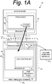
- Fig. 1A shows an example communications system 20 wherein radio access node 22 communicates over air or radio interface 24 with first wireless terminal 26 1 .
- the node 22 comprises node processor 30 and node transmitter 32.
- the first wireless terminal 26 1 comprises terminal processor 40 and terminal transceiver 42.
- the terminal transceiver 42 typically comprises terminal transmitter circuitry 44 and terminal receiver circuitry 46.
- node 22 and first wireless terminal 26 1 communicate with each other across radio interface 24, and may do so using "frames" of information that are typically formatted and prepared by a scheduler of node 22.
- LTE Long Term Evolution
- Each LTE frame may comprise plural subframes.
- each LTE subframe may be divided into two slots.
- the transmitted signal in each slot is described by a resource grid comprised of resource elements (RE).
- LTE Long Term Evolution
- MAC Medium Access Control
- LTE Long Term Evolution
- PDSCH Physical Downlink Shared Channel
- PDSCH is the main physical channel used for unicast data transmission, and is also used for transmission of paging information.
- schedulers assign(s) different parts of the downlink and uplink shared channels to different wireless terminals for reception and transmission respectively.
- the assignments for the shared channels are transmitted in a control region which is provided in the beginning of each downlink subframe.
- the Physical Downlink Control Channel (PDCCH) carries the resource assignment for wireless terminals.
- the wireless terminal When a wireless terminal desires to send information on the uplink to the node 22, the wireless terminal sends a scheduling request to the node 22 followed by a buffer status report (BSR) from which the node 22 can determine that the wireless terminal intends to perform an uplink transmission. Thereafter in a downlink (DL) subframe the node 22 indicates on the Physical Downlink Control Channel (PDCCH) what radio resources the wireless terminal may use for its desired uplink transmission, e.g., the node 22 provides an uplink grant for an uplink transmission.
- BSR buffer status report
- wireless terminals may communicate with one another without having those communications transmitted through the node 22.
- Such terminal-to-terminal communications are also called device-to-device (D2D) communications.
- D2D communications may be under network control or "in-coverage", meaning that one or more of the wireless terminal involved in the device-to-device (D2D) communications may be within range of radio frequencies utilized by a node or cell of a radio access network (RAN).
- RAN radio access network
- D2D device-to-device
- the terminal transceiver 42 preferably comprises terminal transmitter circuitry ("transmitter”) 44 and terminal receiver circuitry (“receiver”) 46.
- the receiver 46 of first wireless terminal 26 1 receives subframe S communicated over radio interface 24 from communications system 20.
- the terminal processor 40 may obtain a device-to-device (D2D) grant from the subframe S.
- the device-to-device (D2D) grant specifies radio resources that first wireless terminal 26 1 is permitted to use for device-to-device (D2D) communication with another wireless terminal, e.g., second wireless terminal 26 2 .
- the transmitter 44 of first wireless terminal 26 1 serves, e.g., to transmit data on the uplink (UL) from first wireless terminal 26 1 to node 22, but may also serve to transmit device-to-device (D2D) data to another wireless terminal(s), e.g., second wireless terminal 26 2 , using the radio resources permitted by the D2D grant.
- D2D device-to-device
- Mode 1 There are two modes of device-to-device (D2D) resource allocation.
- a first mode has several names (all used interchangeably herein), such as “Mode 1", the "eNB scheduled resource allocation mode", and the “network-allocated resource mode”.
- Mode 1 is characterized by: (1) the wireless terminal needing to be RRC_CONNECTED in order to transmit data; (2) the wireless terminal requesting transmission resources from the node (the node schedules transmission resources for transmission of scheduling assignment(s) and data); (3) the wireless terminal sending a scheduling request (D-SR or Random Access) to the node followed by a buffer status report (BSR). Based on the BSR the node can determine that the wireless terminal has data for a ProSe Direct Communication transmission and estimate the resources needed for transmission.
- D-SR scheduling request
- BSR buffer status report
- a second mode also has several names (used interchangeably herein), such as “Mode 2", the “wireless terminal selected resource” mode (or, more simply, the “terminal selected resource mode), and the “wireless terminal (UE) autonomous resource selection mode”.
- Mode 2 is characterized by the wireless terminal (UE) on its own selecting resources from resource pools to transmit scheduling assignment and data. The fact that a wireless terminal selects resources “on its own” indicates that the resource selection is "autonomous”.
- One of the aspects of the technology disclosed herein provides, e.g., techniques for determining when a wireless terminal such as wireless terminal 26 1 is out-of-coverage.
- the wireless terminal 26 1 When out-of-coverage, the wireless terminal 26 1 is no longer entitled for device-to-device (D2D) communications to use the network radio resources which are dynamically allocated by node 22. That is, when out-of-coverage the wireless terminal may not use Mode 1. Instead, when out-of-coverage, the wireless terminal 26 1 must use for device-to-device (D2D) communications (e.g., communications with other wireless terminals such as second wireless terminal 26 2 ) resources selected by the wireless terminal from a pre-configured pool of radio resources (e.g., a wireless terminal selected resource mode). That is, when out-of-coverage the wireless terminal uses Mode 2.
- Fig. 1A shows terminal processor 40 having access to device-to-device (D2D) resource pool 48, which may at least partially be stored in memory for access by terminal processor 40
- Fig. 1A also shows the wireless terminal 26 1 as comprising device-to-device (D2D) controller 50.
- the device-to-device (D2D) controller 50 performs functions for many embodiments and modes described herein.
- the device-to-device (D2D) controller 50 and indeed may wireless terminal 26 1 comprise electronic machinery as described herein with reference to Fig. 5 , for example.
- D2D controller 50 Among the functions performed by device-to-device (D2D) controller 50 are (B) Cell Selection/Re-Selection strategies; (C) determining out-of-coverage situations; (X) determining conditions applicable for the D2D modes; (Y) receiving an indication from node 22 of the particular D2D mode for which the wireless terminal is authorized to operate; (F) determining to use D2D Mode 2 upon occurrence of a physical layer problem; and (G) multi-carrier communications and resource allocation therefor. While one or more of these functions may be performed together in a same example embodiment and mode, each function may also be separately performed without necessarily implementing or involving aspects of other functions.
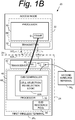
- Fig. 1B shows that the device-to-device (D2D) controller 50 of wireless terminal 26 1 may, in an embodiment and mode, comprise cell selection/re-selection logic 50B.
- Fig. 2 shows basic, example acts or steps involved in a generic method of operating a wireless terminal engaged in device-to-device (D2D) communications, and particularly different types of cell selection/re-selection strategies which may be utilized in conjunction with the example out-of-coverage detection methods. In an example embodiment and mode the acts of Fig. 2 may be performed by cell selection/re-selection logic 50B of device-to-device (D2D) controller 50
- D2D prioritized strategy requires the wireless terminal to consider selection/reselection candidate frequencies at which the wireless terminal cannot receive or transmit device-to-device (D2D) signals to be of low priority candidate frequencies when the wireless terminal is capable of device-to-device (D2D) communications and is receiving or transmitting, or anticipating receiving or transmitting, device-to-device (D2D) signals on device-to-device (D2D) supported frequencies.
- D2D device-to-device
- the wireless terminal is receiving or transmitting, or anticipating receiving or transmitting, device-to-device (D2D) signals on device-to-device (D2D) supported frequencies, and as a result of such actual or anticipated receiving or transmitting the wireless terminal is therefore "camped” on a particular frequency and is receiving the "camped on” frequencies through its receiver circuit 46.
- D2D device-to-device
- D2D device-to-device
- the candidate frequencies at which the wireless terminal cannot receive or transmit device-to-device (D2D) signals are considered in the D2D prioritized strategy of act 2-1 to be low priority candidate frequencies as just stated, then naturally the candidate frequencies at which the wireless terminal can receive or transmit device-to-device (D2D) signals, including the camped-on frequency, are considered to be high priority candidate frequencies. Logically the already camped-on frequency will be considered to be the highest priority candidate frequency.
- Another such cell selection/re-selection strategy which is a refinement of the strategy of act 2-1, represented by act 2-2 and known as the D2D only strategy, requires the wireless terminal (e.g., wireless terminal 26 1 ) to consider only cell selection/reselection candidate frequencies which are device-to-device (D2D)-supported frequencies when the wireless terminal is capable of device-to-device (D2D) communications and is receiving or transmitting, or anticipating receiving or transmitting, device-to-device (D2D) signals on device-to-device (D2D) supported frequencies.
- D2D device-to-device
- D2D device-to-device
- the wireless terminal and particularly terminal processor 40 selects a candidate frequency for use in the device-to-device (D2D) communications.
- the terminal processor 40 may select a high priority candidate as the candidate frequency for use in the device-to-device (D2D) communications.
- the a transceiver 42 is configured to transmit device-to-device (D2D) signals using device-to-device (D2D) radio resources selected in accordance with the cell selection/reselection operation.
- D2D device-to-device
- D2D device-to-device
- terminal processor 40 comprises device-to-device (D2D) controller 50 with coverage detection logic 50C and radio resource control (RRC) state machine 52.
- D2D device-to-device
- RRC radio resource control
- terminal processor 40 and particularly device-to-device (D2D) controller 50 thereof uses predefined RRC Idle state transitions to determine when a wireless terminal engaged in device-to-device (D2D) communications encounters an out-of-coverage situation (e.g., a wireless terminal selected resource mode).
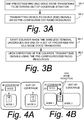
- Fig. 3A shows basic, example acts or steps involved in a generic method of determining when a wireless terminal encounters an out-of-coverage situation for device-to-device (D2D) communications purposes.
- "Device-to-device (D2D) communication purposes" (and likewise sidelink direction communication purposes) may comprise a wireless terminal engaged in device-to-device (D2D) communications (e.g., already participating in device-to-device (D2D) communications) or anticipating participating in device-to-device (D2D) communications.
- the example method of Fig. 3 may be used in conjunction with either the D2D prioritized strategy of act 2-1 or the D2D only strategy of act 2-2.
- Act 3A-1 comprises the terminal processor 40 using a predefined RRC Idle state transition to determine when a wireless terminal engaged in device-to-device (D2D) communications encounters an out-of-coverage situation.
- Act 3A-2 comprises, when the out-of-coverage situation is determined, the terminal processor 40 transmitting (over terminal transmitter circuitry 44) device-to-device (D2D) signals using pre-configured resources.
- act 3A-2 may comprise the terminal processor 40 causing the transmitter 44 of wireless terminal to transmit device-to-device (D2D) signals using resources selected by the wireless terminal from pre-configured device-to-device (D2D) radio resources.
- the pre-configured device-to-device (D2D) resources may, in an example implementation, be the resources of device-to-device (D2D) resource pool 48.
- the predefined RRC Idle state transition comprises any one of the following: (1) the wireless terminal moving to Any Cell Selection State; (2) the wireless terminal moving to Camped Normally State on non-device-to-device (D2D) frequencies; (3) the wireless terminal moving to Camped on Any Cell State on non-device-to-device (D2D) frequencies.
- D2D non-device-to-device
- D2D Any Cell State on non-device-to-device
- Fig. 3B shows basic, example acts or steps involved in a counter-based method of determining when a wireless terminal engaged in device-to-device (D2D) communications encounters an out-of-coverage situation (e.g., a wireless terminal selected resource mode).
- Act 3B-1 which corresponds to an implementation of act 3A-1, comprises the terminal processor 40 starting a resource mode counter 60 (e.g., an out-of-coverage counter) when the wireless terminal undergoes any one of the set of predefined RRC Idle state transitions.
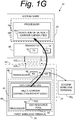
- Fig. 1C shows that, in an example embodiment and mode, device-to-device (D2D) controller 50 may comprises a counter 60, known as the "out-of-coverage" counter or alternatively as the resource mode counter.
- the device-to-device (D2D) controller 50 of terminal processor 40 requests that RRC state machine 52 notify the device-to-device (D2D) controller 50 when any one of the set of predefined RRC Idle state transitions occurs, and such notification from RRC state machine 52 specifies the nature and/or circumstance of the RRC state transition.
- Act 3B-2 comprises, upon expiration of the resource mode counter 60, the wireless terminal transmitting (via terminal transmitter circuitry 44) the device-to-device (D2D) signals (e.g., to wireless terminal 26 2 ) using the resources selected by the wireless terminal from the pre-configured device-to-device (D2D) radio resources rather than using the network-allocated radio resources scheduled by the node.
- the wireless terminal owning the resource mode counter 60 is explicitly declared to be out-of-coverage, e.g., out-of-coverage of device-to-device (D2D) frequencies.
- the wireless terminal is permitted to perform out-of-coverage operations, e.g., to use the D2D radio resource pool 48 for device-to-device (D2D) communications (but not the device-to-device (D2D) frequencies that are allocated by the node 22 using scheduling and grants).
- the wireless terminal is required to obtain device-to-device (D2D) resources/frequencies by scheduling from the node 22 (unless, as described below, the node has provided an indication that wireless terminal may, even when in-coverage, select from the device-to-device (D2D) radio resource pool 48).
- Obtaining device-to-device (D2D) resources/frequencies by scheduling from the node 22 involves sending a scheduling request to node 22 for device-to-device (D2D) resources, and receiving a scheduling grant from the node 22 in return.
- the resource mode counter 60 may be realized as any effective way or apparatus of determining a lapse of time since the wireless terminal was notified by RRC state machine 52 of any one of the set of predefined RRC Idle state transitions.
- resource mode counter 60 comprises a clock which counts elapsing time units.
- resource mode counter 60 may be a count-down timer which has an initial value set and then is decremented by the passage of units of time (e.g., seconds).
- an example time value may be 10 seconds (see, e.g., http://lteworld.org/forums/lteworld-forum/lte-cell-search, search "period").
- the resource mode counter 60 may take other forms, such as a circuit or logic configured to count occurrences of detection of a network event or marker.
- resource mode counter 60 may count or track system frame numbers (SFN).
- an initialization (e.g., "initial") or reference threshold value of resource mode counter 60 may be configurable.
- the initialization value may be, for example, an integer multiple of wireless terminal cell search periods.
- a "wireless terminal cell search period" is understood by the person skilled in the art to be a time window allotted for a wireless terminal to search for a cell, such as may occur when the wireless terminal is powered on, for example.
- the initialization or reference threshold for counter may be multiple attempts of wireless terminal cell search.
- the initialization value of the resource mode counter may be set differently for a first of the predefined RRC Idle state transitions than for a second of the predefined RRC Idle state transitions.
- the timer threshold of resource mode counter 60 for transition from Camped Normally state to Any Cell Selection State can be set higher than the one with transition from Camped on Any Cell state to Any Cell Selection State.
- the resource mode counter 60 is started on condition that the resource mode counter 60 is not already running and is not already expired. It may be that, under certain circumstances, the resource mode counter 60 is started as a result of a first state transition that appears to indicate out-of-coverage, and following that first state transition a second state transition which also appears to indicate out-of-coverage occurs. In such scenario, detection of the second state transition should not "reset” or "restart” the resource mode counter 60, since the cumulative count after the both the first state transition and the second state transition should be taken into consideration regarding the timing of when an actual out-of-coverage occurs. In such scenario, the terminal processor 40 continues operation of the resource mode counter 60 when the wireless terminal undergoes any one of the set of the predefined RRC Idle state transitions and the resource mode counter is already running.
- the method further comprises at least temporarily stopping the counter if any one of the following occurs: (1) the wireless terminal finds a suitable/acceptable cell to camp on in device-to-device (D2D) supported frequencies; (2) the wireless terminal is no longer participating in device-to-device (D2D) services/communications; (3) the wireless terminal determines that the wireless terminal is out-of-coverage; (4) the wireless terminal determines to use resource(s) selected by the wireless terminal from a pre-configured resource; or (5) the wireless terminal leaves the Idle Mode.
- D2D device-to-device
- D2D device-to-device
- the situation in which the wireless terminal determines to use resource(s) selected by the wireless terminal from a pre-configured resource means that the wireless terminal does not have a transitional procedure of determining it is out-of-coverage when the timer expires, and the wireless terminal may start transmitting D2D signals directly.
- the wireless terminal may obtain device-to-device (D2D) resources/frequencies (i.e., network-allocated radio resources) by scheduling from the node 22, but if the wireless terminal is out-of-coverage the wireless terminal uses resources/frequencies from a pre-configured pool.
- D2D device-to-device resources/frequencies
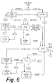
- FIG. 4A Such is illustrated in Fig. 4A in which wireless terminal UE-I is in-coverage of node 22 (and accordingly operates in accordance with Mode 1, using the network-allocated resources scheduled by node 22) but UE-O is out-of-coverage (and thus uses the pre-configured device-to-device (D2D) radio resources).
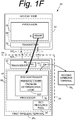
- a radio access node 22 may broadcast an indication that the node supports a mode in which the wireless terminal when in-coverage may use resources selected by the wireless terminal from the pre-configured pool of radio resources (e.g., another form of the terminal selected resource mode). For example, if a wireless terminal is in RRC Idle state, the wireless terminal may receive (e.g., at receiver 46), via broadcasted system information, an indication of supporting of a mode using resources selected by the wireless terminal from a pre-configured pool of radio resources. Fig.
- 1D shows node processor 30 preparing an indication of D2D mode 62 which, as indicated above, may be included in system information (e.g., a system information block) which is understood to be in a subframe S.
- system information e.g., a system information block
- D2D controller 50 of the wireless terminal knows in which mode it may operate.
- the wireless terminal can use the mode using resources selected by the wireless terminal from a pre-configured pool of radio resources until the radio access node instructs the wireless terminal in RRC Connected state to use a mode using network-allocated radio resources scheduled by the radio access node (e.g., network-allocated resource mode).
- the wireless terminal may be required to attempt to access to the radio access node (e.g., performing RRC connection establishment procedure) before and/or during a D2D transmission.
- the wireless terminal When the wireless terminal is in RRC Connected state, the wireless terminal may be instructed by the radio access node to use a mode using network-allocated radio resources scheduled by the radio access node (e.g., network-allocated resource mode). If the wireless terminal received the indication of supporting of a mode using resources selected by the wireless terminal from a pre-configured pool of radio resources, the wireless terminal may not need to use a resource counter. By not sending this indication from the radio access node, the radio access node can protect in-coverage from use of a mode using resources selected by the wireless terminal from a pre-configured pool of radio resources. By sending this indication from the radio access node, the radio access node can provide the wireless terminal an allowance to use the mode using resources selected by the wireless terminal from a pre-configured pool of radio resources.
- network-allocated radio resources e.g., network-allocated resource mode
- the node 22 may, in an example embodiment and mode, send to the wireless terminal an indication which specifies, for device-to-device (D2D) communications with another wireless terminal, whether the wireless terminal is to use network-allocated radio resources or radio resources which are selected by the wireless terminal.
- the node processor 30 may send to the wireless terminal an indication which specifies that the wireless terminal when in network coverage is use radio resources which are selected by the wireless terminal for device-to-device (D2D)communications with the another wireless terminal.
- the node and the wireless terminal operate in a manner as already described. That is, the node 22 receives a scheduling request from the wireless terminal when the wireless terminal desires to send a device-to-device (D2D) communication. Then, in response to the scheduling request, the node 22 sends a grant of the network-allocated radio resources to the wireless terminal in a subframe.
- D2D device-to-device
- the transmitter 32 (transmitter circuitry) of the node 22, along with receiver 34 (receiver circuitry), comprise a node transceiver 36.
- the transceiver 36 is shown only in Fig. 1D , it should be appreciated that the nodes of other example embodiments and modes described herein may also have such a transceiver.
- transmitter 32 transmits the indication 62 over the radio interface to the wireless terminal, and receiver 34 is configured to receive a scheduling request from the wireless terminal.
- the node 22 may send the wireless terminal an indication to use the radio resources which are selected by the wireless terminal occurs when the wireless terminal is in a radio resource control (RRC) Idle state.
- RRC radio resource control
- the pool 48 of radio resources has been described as "pre-configured” and thus the radio resources thereof are available for selection by the wireless terminal in what has been termed a wireless terminal selected resource mode.
- Some of the radio resources of pool 48 may be pre-configured in the sense that radio resources are pre-configured in memory without interaction of the node 22, e.g., preconfigured from an electronic device such as a card (e.g., SIM card or UICC card) installed in the wireless terminal, or from some other circuit entity such as Mobile Equipment (ME).
- Other radio resources of pool 48 may be pre-configured in the sense that radio resources are pre-configured in memory on the basis of information received from the node 22.
- the wireless terminal learns of or obtains the pre-configured resources, it is understood from the foregoing that the node 22 sends to the wireless terminal an indication (e.g., indication of D2D mode 62) of whether the wireless terminal is to use mode 1 resources (e.g., network-allocated resource mode) or mode 2 resources (pre-configured resources from which the wireless terminal makes a resource selection).
- an indication e.g., indication of D2D mode 62
- mode 1 resources e.g., network-allocated resource mode
- mode 2 resources pre-configured resources from which the wireless terminal makes a resource selection
- the wireless terminal may receive, via broadcasted system information, an indication of supporting of a mode using resources selected by the wireless terminal from a pre-configured pool of radio resources, or that the wireless terminal may be instructed by the radio access node to use a mode of network-allocated radio resources scheduled by the radio access node (e.g., network-allocated resource mode).
- a mode of network-allocated radio resources scheduled by the radio access node e.g., network-allocated resource mode
- wireless terminal UE-I is in-coverage of node 22 (and accordingly operates in accordance with Mode 1, using the network-allocated resources scheduled by node 22) but UE-O is out-of-coverage and thus uses the pre-configured device-to-device (D2D) radio resources.
- D2D device-to-device
- the resource mode and coverage-situation may be considered separately as also described above.
- a radio access node 22 may broadcast an indication that the node supports a mode in which the wireless terminal UE-E when in-coverage may use resources selected by the wireless terminal from a pre-configured pool of radio resources (e.g., as in the terminal selected resource mode).
- the ProSe-enabled wireless terminal can operate in two modes for resource allocation: Mode 1 and Mode 2.
- a wireless terminal is considered in-coverage if it has a serving cell (i.e., the wireless terminal is RRC_CONNECTED or is camping on a cell in RRC_IDLE). If a wireless terminal is out of coverage it can only use Mode 2. If the wireless terminal is in coverage it shall use only the mode indicated by the node's grant configuration unless one of the exceptional cases occurs. When an exceptional case occurs the wireless terminal is allowed to use Mode 2 at least temporarily even though it was configured to use Mode 1.
- Mode 1 resource allocation method 1 may cause a "coverage hole" or service discontinuity in coverage when the wireless terminal still camps on a cell but cannot have successful RRC connection with eNodeB, or when the wireless terminal encounters exceptional radio link problems.
- the Mode 2 resource allocation method may generate interference to the network if synchronization errors occur, which will destroy the network. Meanwhile, the issue of load balancing should also be considered for in coverage scenario when one resource allocation method cannot have adequate resource for allocation while the other still has enough resource.
- resource allocation methods are described below for a certain carrier frequency. These procedures and techniques may or may not be limited to single RF capable wireless terminal or to a wireless terminal capable of D2D communication or Public Safety wireless terminal.
- single RF refers to a wireless terminal having one transceiver, e.g., one transmitting circuit and one receiving circuit for handling one baseband.
- multiple RF or the like refers to a wireless terminal having plural transceivers, e.g., plural transmitting circuits and plural receiving circuits for handling respective plural basebands.
- D2D device-to-device
- D2D device-to-device
- D2D device-to-device
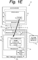
- Mode Condition Determination Logic 50D of device-to-device (D2D) controller 50 as shown in Fig. 1E .
- the wireless terminal If the wireless terminal is capable of D2D communications and is interested in transmitting D2D signals in a carrier frequency, the wireless terminal can transmit D2D signals with Mode 1 if it satisfies one or more of the following conditions or combinations thereof:
- the wireless terminal If the wireless terminal is capable of D2D communications and is interested in transmitting D2D signals in a carrier frequency, the wireless terminal can transmit D2D signal with Mode 2 if it satisfies one or more of the following conditions or combinations thereof:
- the wireless terminal and the mode determination logic 50D of device-to-device (D2D) controller 50 in particular may make a determination regarding a type of radio resources that the wireless terminal may use for device-to-device (D2D) communications with another wireless terminal.
- the determination comprises the wireless terminal making a first mode determination that the wireless terminal should use network-allocated radio resources in accordance with one or more of the Mode 1 Alternative Conditions 1 - 7; or the wireless terminal making a second mode determination that the wireless terminal should use the wireless terminal autonomous resource selected radio resources in accordance with one or more of the one or more of the Mode 2 Alternative Conditions 1 - 8.
- the wireless terminal may make the first mode determination that the wireless terminal should use the network-allocated radio resources if the wireless terminal is in a Radio Resource Control (RRC) Connected state and the wireless terminal is permitted by the node to use the network-allocated radio resources.
- RRC Radio Resource Control
- the wireless terminal may make the second mode determination that the wireless terminal should use the wireless terminal autonomous resource selected radio resources if the wireless terminal is either in a Radio Recourse Control (RRC) Idle state and the wireless terminal is permitted by the node to use the wireless terminal autonomous resource selected radio resources; or in a Radio Resource Control (RRC) Connected state and the wireless terminal is permitted by the node to use the wireless terminal autonomous resource selected radio resources
- RRC Radio Recourse Control
- the wireless terminal may make the second mode determination that the wireless terminal should use the wireless terminal autonomous resource selected radio resources when the wireless terminal experiences a predetermined radio link problem, such as a radio link failure or repeated failure of a RRC connection request when the wireless terminal camps on a cell.
- a predetermined radio link problem such as a radio link failure or repeated failure of a RRC connection request when the wireless terminal camps on a cell.
- the transmitter 44 of the wireless terminal transmits device-to-device (D2D) signals to another wireless terminal (e.g., wireless terminal 26 2 ) using the radio resources according to either the first mode determination or the second mode determination.
- D2D device-to-device
- the wireless terminal may use the D2D Mode 2, e.g., may use the wireless terminal autonomous selected radio resources if the wireless terminal meets exceptional radio link problems (e.g., RLF or RRC connection request fails several times when the wireless terminal camps on a cell).
- exceptional radio link problems e.g., RLF or RRC connection request fails several times when the wireless terminal camps on a cell.
- RLF radio link failure
- the wireless terminal uses at least some wireless terminal autonomous selected device-to-device (D2D) radio resources for device-to-device (D2D) communications with another wireless terminal when the wireless terminal is in coverage of the radio access network.
- D2D device-to-device
- transmitter 44 is configured to transmit device-to-device (D2D) signals to the another wireless terminal (e.g., wireless terminal 26 2 ) using at least some wireless terminal autonomous selected device-to-device (D2D) radio resources when the wireless terminal is in coverage of the radio access network and the physical layer problem is determined.
- D2D device-to-device
- the predetermined physical layer condition comprises a radio link failure.
- the method of Fig. IF may further comprise the wireless terminal obtaining the at least some wireless terminal autonomous selected device-to-device (D2D) radio resources from a pre-configured pool of radio resources stored in a memory of the wireless terminal, e.g., pool 48.
- the wireless terminal may use the at least some wireless terminal autonomous selected device-to-device (D2D) radio resources for device-to-device (D2D) communications with the another wireless terminal until the wireless terminal when in a RRC Connected state receives a subsequent instruction to use different radio resources.
- a wireless terminal may be capable of multi-carrier communications, e.g., capable of sending D2D signals, and as such may operate using a first carrier frequency and at least a second carrier frequency.
- D2D signal includes channels, reference signals and synchronization signals for D2D communication and/or discovery.
- Multicarrier communications can be performed by a wireless terminal capable of single RF or a wireless terminal capable of multiple RF.
- a wireless terminal capable of single RF e.g., single radio frequency operation
- has one transceiver one transmitter and one receiver
- a wireless terminal capable of multiple RF comprises multiple transceivers and may handle multiple basebands, with each transceiver possibly processing more than one carrier frequency.
- the wireless terminal has to know what radio resources to use for both its wide area network (WAN) communications and its device-to-device (D2D) communications.
- WAN wide area network
- D2D device-to-device
- a wireless terminal is capable of multi-carrier communications, choice of resource allocation methods becomes more complicated.
- Two service types, D2D service and wide area network (WAN) service, are considered herein for D2D capable UE multi-carrier communications.
- Different countries may have different radio spectrum allocation policies. Some countries may allocate dedicated carrier frequency band for public safety usage; other countries may allow the carrier frequency sharing between D2D service and WAN service. Consequently, different spectrum allocation scenarios substantially affect the resource allocation methods. UE therefore uses the different alternative methods according to different scenarios.
- an implementation of the method if the UE in RRC_IDLE is camped in a first carrier frequency or UE in RRC_CONNECTED is served in a serving cell in a first carrier frequency, the UE uses only mode 2 to transmit a D2D signal in a second carrier frequency.
- the wireless terminal e.g., UE
- the wireless terminal has to determine whether it can use mode 2 or not based on a certain criteria. As described herein, such criteria may include the capability information of the wireless terminal.
- the node 22 e.g., eNodeB
- the wireless terminal may inform the node 22 of its UE capability information related to support of transmitting the D2D signal for each band combination.
- a fundamental point of these methods is, for a single wireless terminal no matter how many radio frequency (RF) chains are supported, only one RRC_CONNECTED state is allowed for two reasons: (1) wireless terminal implementation feasibility and complexity; and (2) two RRC_CONNECTED states in one wireless terminal practically means the fact that these are two wireless terminals.
- a "radio frequency (RF) chain” essentially means how many transceivers the wireless terminal may have, e.g., how many baseband signals can be processed.
- a wireless terminal that supports two RF chains for example, is essentially two wireless terminals co-located in one wireless terminal device.
- the wireless terminal may be configured with multiple serving cells. Therefore, “first carrier frequencies” may be used for multiple serving cells, but “a first carrier frequency” may be used for a single serving cell. In RRC_IDLE, the wireless terminal may only camp on a single cell. Therefore, the terminology “first carrier frequency” may herein apply to any or all of the scenarios described in this paragraph.
- the first carrier frequency(ies) are a set of carrier frequency(ies) which are used for WAN services for the wireless terminal.
- the second carrier frequencies are a set of D2D carrier frequency(ies) which are used for D2D services for the wireless terminal.
- the second carrier frequency(ies) may be D2D dedicated for the wireless terminal.
- the first carrier frequency(ies) may be shared by D2D and WAN for the wireless terminal.
- the first carrier frequencies and the second carrier frequencies for the wireless terminal may be the same set or different sets. From a system perspective, one wireless terminal may use a frequency as the first frequency and another may use it as the second frequency. A frequency may be dedicated to D2D from a system perspective.
- mode 1 can be configured only in the first carrier frequency (ies).
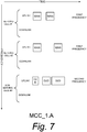
- Fig.7 shows a case scenario MCC_1.A for a wireless terminal in RRC_CONECTED.
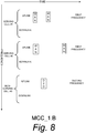
- Fig.8 shows a case scenario MCC_1.B for a wireless terminal in RRC_CONNECTED.
- Fig.9 shows a case scenario MCC_2.A for a wireless terminal in RRC_CONECTED.
- Fig.10 shows a case scenario MCC_2.B for a wireless terminal in RRC_CONECTED.
- Fig.11 shows a case scenario MCC_3.A for a wireless terminal in RRC_CONECTED.
- Fig.12 shows a case scenario MCC_3.B for a wireless terminal in RRC_CONECTED.
- Fig.13 shows sharing a frequency by WAN and D2D described above.
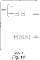
- Fig.14 shows a case scenariofor a wireless terminal in RRC_IDLE.
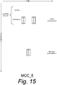
- Fig.15 shows a case scenario for a wireless terminal in RRC IDLE.
- Fig. 7 - Fig. 15 thus show, from the perspective of a wireless terminal, several example scenarios of timing of transmission of various signals, including WAN signals (e.g., signals between the wireless terminal and a node 22) and device-to-device (D2D) signals (between the wireless terminal and another D2D-capable D2D wireless terminal).
- WAN signals e.g., signals between the wireless terminal and a node 22
- D2D device-to-device
- Fig.7 to Fig. 15 examples of conditions of transmissions and receptions on WAN and D2D from a wireless terminal perspective are shown but conditions may not be limited to these examples.
- FIG. 13 show one or both of transmission and reception on a first frequency with a first serving cell (serving cell #1), transmission and reception on the first frequency with a second serving cell (serving cell #2), and transmission and reception on a second frequency with a non-serving cell (non-serving cell #3).
- Fig. 14 and Fig. 15 show transmissions for RRC_IDLE mode and thus transmissions with a camped cell.
- multi-carrier communications includes the following meaning/scenarios:
- the tariff controller 50 of the example embodiment and mode of Fig. 1G comprises multi-carrier communications capabilities report logic 50D, also known as multi-carrier communications capabilities report generator 50D.
- the wireless terminal of Fig. 1G includes a processor which is configured to generate an indication of capability of the wireless terminal to support multi-channel communications comprising plural frequency bands.
- Fig. 1G shows an indication of UE multi-carrier communications capability 64 being provided by the wireless terminal to node 22 as depicted by the arrow in Fig. 1G .
- the tariff controller 50 and thus the processor 40 of the wireless terminal is configured to generate capability information related to support transmission of D2D communications for combinations of the plural frequency bands.
- the transceiver 42 sends the capability information to the node 22 and uses at least one of the plural frequency bands for device-to-device (D2D) communications in sending device-to-device (D2D) communications to another wireless terminal, e.g., wireless terminal 26 2 .
- the D2D resource allocation techniques or methods for which capabilities of the wireless terminal which may be communicated to the node in the UE multi-carrier communications capability indication 64 comprise the following:
- the processor of the wireless terminal of Fig. 1G is configured, as included in the techniques listed above, to make a determination whether the wireless terminal is to use only wireless terminal autonomous selected device-to-device (D2D) radio resources to transmit a device-to-device (D2D) signal in a second carrier frequency to another D2D-capable wireless terminal when the wireless terminal is either (1) in RRC_IDLE mode and camping on a first carrier frequency or (2) in RRC_CONNECTED mode and served by a serving cell in a first carrier frequency.
- D2D device-to-device
- the processor 40 may make a determination of one or more resource allocation techniques that the wireless terminal is eligible to employ for the multi-band frequencies. Further, it is understood from the foregoing listing of techniques that the processor may make the determination of the one or more resource allocation techniques based on one or more of the following: a radio resource control state of the wireless terminal ; and, a type of radio resources allocated to a first frequency carrier.
- the capability indication 64 may comprises identification of the one or more resource allocations techniques (such as the above-listed techniques) that the wireless terminal is eligible to employ for the multi-band frequencies.
- Fig. 1H shows in more detail an example embodiment of the radio communications network of any and all of the example embodiments and modes of Fig. 1A - Fig. 1H .
- Fig. 1H is just one example implementation of how the node 22 and first wireless terminal 26 1 may be carried out structurally and/or functionally.
- the example embodiments an modes of Fig. 1A - Fig. 1H are preferably implemented using electronic machinery.
- the node 22 comprises node electronic machinery 66; first wireless terminal 26 1 comprises terminal electronic machinery 68.
- various units and functionalities as framed by broken lines of node 22 and first wireless terminal 26 1 are implemented by node electronic machinery 66 and terminal electronic machinery 68, respectively. What comprises node "electronic machinery" is discussed in more detail with reference to Fig. 5 .
- the node 22 comprises node processor 30, also known as a frame processor, and node transmitter 32.
- the node transmitter 32 typically includes plural antenna 32A.
- the node processor 30 is shown in more detail as comprising node scheduler 70 and node frame handler 72.
- the node scheduler 70 prepares or formats, into frames, information to be transmitted by node transmitter 32 on the downlink (DL) from node 22 to first wireless terminal 26 1 (as well as to other wireless terminals).
- the node frame handler 72 serves, e.g., to process information received in frames on the uplink from wireless terminals, e.g., first wireless terminal 26 1 .
- the first wireless terminal 26 1 comprises terminal processor 40 and terminal transceiver 42.
- the terminal transceiver 42 typically includes plural antenna 42A.
- the terminal processor 40 of first wireless terminal 26 1 of Fig. 1H also known as a frame processor, comprises terminal scheduler 80 and terminal frame handler 82.
- the terminal frame handler 82 analyzes a downlink (DL) portion of a frame as received over radio interface 24 from node 22.
- the terminal scheduler 80 prepares uplink frame for transmission to node 22 or, in the case of device-to-device (D2D) communications, to other wireless terminals such as wireless terminal 26 2 .
- D2D device-to-device
- the first wireless terminal 26 1 also comprises executable applications 84 and one or more user interfaces (GUIs) 86.
- the user interfaces (GUIs) 86 may be used to operate or interact with one or more of the executable applications 84.
- One or more of the applications 84 when executed, may prompt or involve device-to-device (D2D) communications with another wireless terminal, e.g., second wireless terminal 26 2 .
- D2D device-to-device
- terminal D2D controller 50 superintends or controls the device-to-device (D2D) communications.
- node electronic machinery 66 certain units and functionalities of node 22 framed by broken line are, in an example embodiment, implemented by node electronic machinery 66.
- first wireless terminal 26 1 framed by broken line are, in an example embodiment, implemented by terminal electronic machinery 68.
- Fig. 5 shows an example of such electronic machinery, whether node electronic machinery 66 or terminal electronic machinery 68, as comprising one or more processors 90, program instruction memory 92; other memory 94 (e.g., RAM, cache, etc.); input/output interfaces 96; peripheral interfaces 98; support circuits 99; and busses 100 for communication between the aforementioned units.
- the memory 94 may be one or more of readily available memory such as random access memory (RAM), read only memory (ROM), floppy disk, hard disk, flash memory or any other form of digital storage, local or remote, and is preferably of non-volatile nature.
- RAM random access memory
- ROM read only memory
- floppy disk hard disk
- flash memory any other form of digital storage, local or remote, and is preferably of non-volatile nature.
- the support circuits 99 are coupled to the processors 90 for supporting the processor in a conventional manner. These circuits include cache, power supplies, clock circuits, input/output circuitry and subsystems, and the like.
- the resource mode counter 60 may be realized by any appropriate structure, such as a timer (e.g., a clock-down timer) or other event counter that reasonably accurately detects lapse of time since a predetermined Idle State transition.
- a timer e.g., a clock-down timer
- a count-up timer which, after a predetermined state transition is utilized, reaches a maximum time-out value may be used to determine out-of-coverage.
- the wireless terminal upon any state transition to Any Cell Selection State ( Camped Normally state to Any Cell Selection State, Camped on Any Cell state to Any Cell Selection State), the wireless terminal shall start resource mode counter 60. Upon any state transition to Camped Normally on non-D2D frequencies, the wireless terminal shall start the resource mode counter 60, if it is not running or not expired. Upon any state transition to Camped on Any Cell on non-D2D frequencies, the wireless terminal shall start the resource mode counter 60, if it is not running or not expired.
- the wireless terminal may be triggered to restart the counter 60, if the counter 60 is running.
- the technology disclosed herein provides numerous benefits, including determining out-of-coverage condition on the basis of downlink received power since camping procedures are essentially based on downlink received power.
- counters such as resource mode counter 60 are easily implemented in current networks such as Long Term Evolution (LTE) networks. Yet further, impacts on both legacy Long Term Evolution (LTE) specifications and current cellular services are minimized.
- LTE Long Term Evolution
- the processes and methods of the disclosed embodiments may be discussed as being implemented as a software routine, some of the method steps that are disclosed therein may be performed in hardware as well as by a processor running software. As such, the embodiments may be implemented in software as executed upon a computer system, in hardware as an application specific integrated circuit or other type of hardware implementation, or a combination of software and hardware.
- the software routines of the disclosed embodiments are capable of being executed on any computer operating system, and is capable of being performed using any CPU architecture.
- the functional blocks may include or encompass, without limitation, digital signal processor (DSP) hardware, reduced instruction set processor, hardware (e.g., digital or analog) circuitry including but not limited to application specific integrated circuit(s) [ASIC], and/or field programmable gate array(s) (FPGA(s)), and (where appropriate) state machines capable of performing such functions.
- DSP digital signal processor
- ASIC application specific integrated circuit
- FPGA field programmable gate array
- a computer is generally understood to comprise one or more processors or one or more controllers, and the terms computer and processor and controller may be employed interchangeably herein.
- the functions may be provided by a single dedicated computer or processor or controller, by a single shared computer or processor or controller, or by a plurality of individual computers or processors or controllers, some of which may be shared or distributed.
- processor or “controller” shall also be construed to refer to other hardware capable of performing such functions and/or executing software, such as the example hardware recited above.
- Nodes that communicate using the air interface also have suitable radio communications circuitry.
- the technology can additionally be considered to be embodied entirely within any form of computer-readable memory, such as solid-state memory, magnetic disk, or optical disk containing an appropriate set of computer instructions that would cause a processor to carry out the techniques described herein.
- D2D Device-to-device
- SA SCI (Sidelink Control Information) on PSCCH (Physical Sidelink Control Channel)
- PD2DSCH Physical Sidelink Control Channel
- PSBCH Physical Sidelink Broadcast Channel
- D2DSS D2D synchronization signals
- SLSS Sidelink Synchronization Signals
- PSSCH Physical Sidelink Shared Channel
Claims (6)
- Procédé réalisé dans un terminal sans fil (261) qui est un équipement utilisateur, UE, le procédé comprenant :générer des informations de capacité de terminal sans fil, pour chacune d'une ou plusieurs combinaisons de bandes, indiquant si le terminal sans fil (261) dans RRC_CONNECTED supporte ou non une transmission simultanée d'une pluralité de communications consistant en communication entre le terminal sans fil (261) et une station de base (22) et en communication de dispositif à dispositif, D2D, la communication D2D étant réalisée directement entre le terminal sans fil (261) et un autre terminal sans fil (262) ; ettransmettre les informations de capacité de terminal sans fil à la station de base (22).
- Procédé de la revendication 1, dans lequel le terminal sans fil (261) dans RRC_CONNECTED est servi dans une cellule en service dans une première fréquence porteuse, et le terminal sans fil (261) réalise la communication D2D dans une deuxième fréquence porteuse différente de la première fréquence porteuse.
- Procédé de la revendication 1, dans lequel la une ou plusieurs combinaisons de bandes incluent des fréquences porteuses utilisées pour de multiples cellules en service.
- Terminal sans fil (261) qui est un équipement utilisateur, UE, comprenant :un processeur (40) configuré pour générer des informations de capacité de terminal sans fil, pour chacune d'une ou plusieurs combinaisons de bandes, indiquant si le terminal sans fil (261) dans RRC_CONNECTED supporte ou non une transmission simultanée d'une pluralité de communications consistant en communication entre le terminal sans fil (261) et une station de base (22) et en communication de dispositif à dispositif, D2D, la communication D2D étant réalisée directement entre le terminal sans fil (261) et un autre terminal sans fil (262) ; etun transmetteur (44) configuré pour transmettre les informations de capacité de terminal sans fil à la station de base (22).
- Terminal sans fil (261) de la revendication 4, dans lequel le terminal sans fil (261) dans RRC_CONNECTED est servi dans une cellule en service dans une première fréquence porteuse, et le terminal sans fil (261) réalise la communication D2D dans une deuxième fréquence porteuse différente de la première fréquence porteuse.
- Terminal sans fil (261) de la revendication 4, dans lequel la une ou plusieurs combinaisons de bandes incluent des fréquences porteuses utilisées pour de multiples cellules en service.
Applications Claiming Priority (2)
| Application Number | Priority Date | Filing Date | Title |
|---|---|---|---|
| US201461990658P | 2014-05-08 | 2014-05-08 | |
| PCT/US2015/021045 WO2015171202A1 (fr) | 2014-05-08 | 2015-03-17 | Appareil et procédés de communication de dispositif à dispositif |
Publications (3)
| Publication Number | Publication Date |
|---|---|
| EP3141038A1 EP3141038A1 (fr) | 2017-03-15 |
| EP3141038A4 EP3141038A4 (fr) | 2017-12-27 |
| EP3141038B1 true EP3141038B1 (fr) | 2020-07-22 |
Family
ID=54369079
Family Applications (1)
| Application Number | Title | Priority Date | Filing Date |
|---|---|---|---|
| EP15789525.1A Active EP3141038B1 (fr) | 2014-05-08 | 2015-03-17 | Appareil et procédés de communication de dispositif à dispositif |
Country Status (5)
| Country | Link |
|---|---|
| US (1) | US10506604B2 (fr) |
| EP (1) | EP3141038B1 (fr) |
| JP (1) | JP6407304B2 (fr) |
| CN (1) | CN106233780B (fr) |
| WO (1) | WO2015171202A1 (fr) |
Families Citing this family (42)
| Publication number | Priority date | Publication date | Assignee | Title |
|---|---|---|---|---|
| WO2015063185A1 (fr) | 2013-10-31 | 2015-05-07 | Telefonaktiebolaget L M Ericsson (Publ) | Procédé, dispositif de communication, et programme informatique |
| EP3515135B1 (fr) | 2014-01-29 | 2021-03-10 | Interdigital Patent Holdings, Inc. | Sélection de ressource pour une découverte ou une communication entre des dispositifs |
| CN106575994B (zh) | 2014-03-18 | 2020-12-11 | 夏普株式会社 | 无线接入节点及其方法、无线终端及其方法 |
| JP6533529B2 (ja) * | 2014-03-18 | 2019-06-19 | シャープ株式会社 | デバイス・ツー・デバイス通信装置および方法 |
| EP3120641B1 (fr) | 2014-03-19 | 2021-01-20 | Interdigital Patent Holdings, Inc. | Synchronisation de dispositif-à-dispositif |
| WO2015147531A1 (fr) * | 2014-03-24 | 2015-10-01 | 엘지전자 주식회사 | Procédé pour déterminer une couverture de cellule pour une opération de dispositif à dispositif (d2d) réalisée par un terminal dans un système de communication sans fil, et terminal utilisant le procédé |
| JP6483154B2 (ja) | 2014-05-01 | 2019-03-13 | シャープ株式会社 | デバイス・ツー・デバイス通信装置および方法 |
| EP3141038B1 (fr) | 2014-05-08 | 2020-07-22 | Sharp Kabushiki Kaisha | Appareil et procédés de communication de dispositif à dispositif |
| US20170086238A1 (en) * | 2014-05-15 | 2017-03-23 | Lg Electronics Inc. | As-nas interaction method for d2d communication and apparatus for the same in wireless communication system |
| CN106465384B (zh) * | 2014-05-16 | 2020-01-07 | 瑞典爱立信有限公司 | 通信系统、网络节点、通信设备、方法和计算机程序 |
| US10129898B2 (en) * | 2014-06-20 | 2018-11-13 | Lg Electronics Inc. | Method for determining resource for device-to-device (D2D) communication in wireless communication system and apparatus therefor |
| CN106416405A (zh) | 2014-06-27 | 2017-02-15 | 夏普株式会社 | 用于设备对设备通信的资源池访问 |
| WO2016022666A1 (fr) | 2014-08-06 | 2016-02-11 | Sharp Laboratories Of America, Inc. | Signaux de synchronisation pour communications de dispositif à dispositif |
| US9894651B2 (en) * | 2014-08-08 | 2018-02-13 | Samsung Electronics Co., Ltd. | Methods and apparatus for resource allocation for D2D communications |
| WO2016064195A2 (fr) * | 2014-10-21 | 2016-04-28 | 엘지전자 주식회사 | Procédé et appareil d'émission et de réception de signaux d2d dans un système de communication sans fil |
| CN107079506B (zh) * | 2014-10-31 | 2020-06-05 | 索尼公司 | 用户设备、通信系统和控制用户设备的方法 |
| US9699154B2 (en) | 2015-01-19 | 2017-07-04 | Intel IP Corporation | Systems, methods and devices for direct communication using a PC5 protocol |
| US11356834B2 (en) * | 2015-01-21 | 2022-06-07 | Samsung Electronics Co., Ltd. | System and method of D2D discovery message transmission |
| US10182419B2 (en) * | 2015-01-29 | 2019-01-15 | Sony Corporation | Telecommunications apparatus and methods |
| US10064124B2 (en) * | 2015-02-06 | 2018-08-28 | Telefonaktiebolaget Lm Ericsson (Publ) | Communication device, network node, and computer program for communication and/or device-to-device operation in an out of coverage state |
| US20180115873A1 (en) * | 2015-03-19 | 2018-04-26 | Nec Corporation | Apparatus and method for proximity-based service communication |
| WO2016163824A1 (fr) * | 2015-04-08 | 2016-10-13 | 엘지전자 주식회사 | Procédé de priorisation sélective de fréquence exécuté par un terminal dans un système de communication sans fil, et terminal utilisant ce procédé |
| CN107409027B (zh) * | 2015-04-09 | 2021-01-19 | 苹果公司 | 用户设备的装置和演进节点b的装置 |
| WO2016164510A1 (fr) | 2015-04-09 | 2016-10-13 | Sharp Laboratories Of America, Inc. | Procédé et appareil permettant de mettre en œuvre une couverture partielle et paquets de ressources de découverte de liaison latérale hors couverture pour des communications sans fil |
| KR102510207B1 (ko) * | 2015-04-17 | 2023-03-16 | 삼성전자주식회사 | 사용자 단말에서 #14 원인을 가지는 attach 거절 메시지를 처리하기 위한 방법 |
| US10616864B2 (en) | 2015-08-07 | 2020-04-07 | Sharp Kabushiki Kaisha | Allocating resources for wireless sidelink direct communications |
| EP3352402B1 (fr) | 2015-09-15 | 2021-01-20 | LG Electronics Inc. | Procédé de sélection de ressource pour un fonctionnement v2x de terminal dans un système de communication sans fil, et terminal mettant en oeuvre ce procédé |
| US10223061B2 (en) * | 2015-12-17 | 2019-03-05 | International Business Machines Corporation | Display redistribution between a primary display and a secondary display |
| EP3809756B1 (fr) * | 2015-12-31 | 2023-11-08 | Huawei Technologies Co., Ltd. | Procédés de gestion de mobilité, appareil, système de communication et support de stockage lisible par ordinateur |
| US10383035B2 (en) | 2016-09-29 | 2019-08-13 | Sharp Laboratories Of America, Inc. | Providing and obtaining system information for remote wireless terminal |
| WO2018083381A1 (fr) * | 2016-11-04 | 2018-05-11 | Nokia Technologies Oy | Amélioration de la mobilité en mode repos pour un équipement utilisateur distant hors couverture |
| WO2018169342A1 (fr) * | 2017-03-17 | 2018-09-20 | 엘지전자 주식회사 | Procédé de réglage et de commande de porteuse pour communication de dispositif à dispositif dans un système de communication sans fil et dispositif correspondant |
| WO2018174684A1 (fr) * | 2017-03-24 | 2018-09-27 | 엘지전자 주식회사 | Procédé et appareil pour transmettre un signal de liaison latérale dans un système de communication sans fil |
| IT201700035262A1 (it) * | 2017-03-30 | 2018-09-30 | Telecom Italia Spa | Rete di dispositivi senza fili configurabile |
| WO2018212690A1 (fr) * | 2017-05-16 | 2018-11-22 | Telefonaktiebolaget Lm Ericsson (Publ) | Procédé, nœud de réseau et équipement utilisateur d'un réseau sans fil permettant de gérer un équipement utilisateur |
| CN109246774B (zh) * | 2017-06-16 | 2021-01-05 | 华为技术有限公司 | 通信方法及装置 |
| WO2019127283A1 (fr) * | 2017-12-28 | 2019-07-04 | Oppo广东移动通信有限公司 | Procédé de communication sans fil, équipement terminal et dispositif réseau |
| CN112106390B (zh) * | 2018-05-11 | 2023-06-16 | 索尼公司 | 移动电子装置和对其能力进行报告的方法与介质 |
| EP4164328A1 (fr) * | 2018-08-06 | 2023-04-12 | Samsung Electronics Co., Ltd. | Procédé et appareil d'émission ou de réception de signal dans un système de communication mobile |
| KR102539350B1 (ko) * | 2018-08-09 | 2023-06-07 | 주식회사 케이티 | 사이드 링크 송수신 방법 및 그 단말 |
| CN111328154B (zh) * | 2018-12-14 | 2022-03-29 | 大唐移动通信设备有限公司 | 一种无线资源控制连接管理方法及终端 |
| US11438878B1 (en) * | 2021-03-24 | 2022-09-06 | Qualcomm Incorporated | Sub-resource pool for transmission of new radio sidelink over unlicensed bands |
Citations (1)
| Publication number | Priority date | Publication date | Assignee | Title |
|---|---|---|---|---|
| US20130051288A1 (en) * | 2011-08-22 | 2013-02-28 | Sharp Laboratories Of America, Inc. | User equipment capability signaling |
Family Cites Families (109)
| Publication number | Priority date | Publication date | Assignee | Title |
|---|---|---|---|---|
| CA2357932A1 (fr) | 2001-09-27 | 2003-03-27 | Alcatel Canada Inc. | Methode de synchronisation de liaisons optiques paralleles entre des dispositifs de communication |
| CN1622677A (zh) | 2003-11-27 | 2005-06-01 | 皇家飞利浦电子股份有限公司 | 一种无线通信网络中支持点到点通信切换的方法 |
| JP4460616B2 (ja) | 2007-11-16 | 2010-05-12 | 株式会社エヌ・ティ・ティ・ドコモ | セル選択方法及び移動局 |
| EP2340681B1 (fr) | 2008-09-25 | 2014-11-12 | Nokia Corporation | Synchronisation d'une communication de dispositif à dispositif |
| CN101772110B (zh) | 2009-01-06 | 2015-01-28 | 中兴通讯股份有限公司 | 一种家庭基站小区间的重选方法 |
| US9622131B2 (en) | 2010-03-05 | 2017-04-11 | Nokia Technologies Oy | Handover of direct peer to peer communication |
| US9084195B2 (en) | 2010-04-01 | 2015-07-14 | Nokia Technologies Oy | Multiple timing advance and carrier aggregation |
| EP2572536B1 (fr) | 2010-05-21 | 2016-04-20 | Telefonaktiebolaget LM Ericsson (publ) | Procédé et agencement dans un réseau de communication sans fil |
| US9295038B2 (en) | 2010-11-16 | 2016-03-22 | Telefonaktiebolaget L M Ericsson (Publ) | Control channel configuration in a wireless communications system |
| US8401562B2 (en) | 2010-11-17 | 2013-03-19 | Nokia Corporation | Apparatus and method employing scheduler behavior aware predictive resource selection in a communication system |
| US8744458B2 (en) | 2010-11-19 | 2014-06-03 | Nokia Corporation | Signaling mixed resource allocations for D2D communications |
| CN102083138B (zh) * | 2011-01-14 | 2017-04-05 | 北京邮电大学 | 一种d2d用户对可同时复用多个蜂窝用户资源的方法 |
| US9888458B2 (en) | 2011-02-11 | 2018-02-06 | Lg Electronics Inc. | Method and apparatus for performing device-to-device cooperative communication in wireless access system |
| KR20140044355A (ko) | 2011-06-01 | 2014-04-14 | 가부시키가이샤 엔티티 도코모 | 소형 노드 디바이스들을 이용한 모바일 통신에서의 향상된 로컬 액세스 |
| EP2739099B1 (fr) | 2011-07-29 | 2019-09-25 | NEC Corporation | Station sans fil, terminal sans fil et procédé de commande de temporisateur d'alignement temporel dans un système de communication sans fil |
| US20130051277A1 (en) | 2011-08-30 | 2013-02-28 | Renesas Mobile Corporation | Method and apparatus for allocating resources for device-to-device discovery |
| US9226206B2 (en) | 2011-09-12 | 2015-12-29 | Ntt Docomo, Inc. | Method and apparatus at the physical and link layer for mobile communications |
| JP6130836B2 (ja) | 2011-09-12 | 2017-05-17 | 株式会社Nttドコモ | Fddリソース割り当てを用いる移動通信における拡張ローカルアクセス |
| CN103037450B (zh) * | 2011-09-29 | 2017-01-25 | 华为技术有限公司 | 一种通信模式切换的方法和装置 |
| JP5813241B2 (ja) * | 2011-10-14 | 2015-11-17 | テレフオンアクチーボラゲット エル エム エリクソン(パブル) | ユーザ機器及び無線ネットワークノード、並びにそれらにおけるデバイスツーデバイス通信のための方法 |
| GB2496153B (en) * | 2011-11-02 | 2014-07-02 | Broadcom Corp | Device-to-device communications |
| CN103999489A (zh) | 2011-12-08 | 2014-08-20 | 诺基亚通信公司 | D2d群集中的设备的网络同步 |
| KR20130065002A (ko) * | 2011-12-09 | 2013-06-19 | 한국전자통신연구원 | 단말간 직접 통신 제어 방법 |
| GB2497589A (en) | 2011-12-16 | 2013-06-19 | Renesas Mobile Corp | Resource Allocation in a Wireless Communication System |
| WO2013109100A1 (fr) | 2012-01-18 | 2013-07-25 | 엘지전자 주식회사 | Procédé de communication entre dispositifs et dispositif associé |
| GB2498575A (en) | 2012-01-20 | 2013-07-24 | Renesas Mobile Corp | Device-to-device discovery resource allocation for multiple cells in a device-to-device discovery area |
| KR101999094B1 (ko) | 2012-01-25 | 2019-07-11 | 한국전자통신연구원 | 무선 통신 시스템에서 단말 대 단말 통신 방법 |
| EP2751946A1 (fr) | 2012-01-25 | 2014-07-09 | Fujitsu Limited | Canal de liaison montante pour communication sans fil |
| US8953478B2 (en) | 2012-01-27 | 2015-02-10 | Intel Corporation | Evolved node B and method for coherent coordinated multipoint transmission with per CSI-RS feedback |
| US9503914B2 (en) | 2012-01-31 | 2016-11-22 | Apple Inc. | Methods and apparatus for enhanced scrambling sequences |
| KR20130093953A (ko) | 2012-02-15 | 2013-08-23 | 삼성전자주식회사 | 단말간 통신을 지원하는 방법 및 장치 |
| US9185690B2 (en) | 2012-02-29 | 2015-11-10 | Sharp Kabushiki Kaisha | Allocating and determining resources for a device-to-device link |
| CN103368713B (zh) * | 2012-03-26 | 2017-03-15 | 中兴通讯股份有限公司 | 设备到设备的通信方法及装置 |
| WO2013157870A1 (fr) | 2012-04-19 | 2013-10-24 | 엘지전자 주식회사 | Procédé de transmission d'informations de commande pour communication d2d directe dans des systèmes de communication sans fil, et appareil associé |
| KR102110214B1 (ko) | 2012-04-26 | 2020-05-13 | 한국전자통신연구원 | 부분적 단말 제어 단말 대 단말 통신 방법 |
| US9674760B2 (en) | 2012-04-27 | 2017-06-06 | Lg Electronics Inc. | Method and device for performing device-to-device communication in wireless communication system |
| CN104272707B (zh) | 2012-04-27 | 2018-04-06 | 交互数字专利控股公司 | 支持邻近发现过程的方法和装置 |
| EP2665298B1 (fr) | 2012-05-15 | 2014-07-09 | Telefonaktiebolaget L M Ericsson (publ) | Gestion de balise pour communication de dispositif à dispositif (D2D) assistée par réseau |
| CN104350778A (zh) | 2012-05-31 | 2015-02-11 | 交互数字专利控股公司 | 设备到设备(d2d)链路自适应 |
| TWI620459B (zh) | 2012-05-31 | 2018-04-01 | 內數位專利控股公司 | 在蜂巢式通訊系統中賦能直鏈通訊排程及控制方法 |
| US10045386B2 (en) | 2012-05-31 | 2018-08-07 | Interdigital Patent Holdings, Inc. | Method and apparatus for device-to-device (D2D) mobility in wireless systems |
| US9125122B2 (en) * | 2012-06-09 | 2015-09-01 | Apple Inc. | Paging for circuit switched fallback (CSFB) in long term evolution (LTE) connected mode |
| WO2014003457A1 (fr) | 2012-06-28 | 2014-01-03 | 엘지전자 주식회사 | Procédé et appareil pour effectuer une communication de dispositif à dispositif dans un système de communication sans fil |
| US9445446B2 (en) | 2012-07-09 | 2016-09-13 | Industrial Technology Research Institute | Method and apparatus for device to device communication |
| EP3547788B1 (fr) | 2012-07-20 | 2020-09-16 | LG Electronics Inc. | Procédé et appareil de transmission de message de dispositif à dispositif associé dans un système de communication sans fil |
| JP5826937B2 (ja) | 2012-07-27 | 2015-12-02 | 京セラ株式会社 | 移動通信システム、基地局、ユーザ端末、及びプロセッサ |
| EP2879454A4 (fr) | 2012-07-27 | 2016-07-06 | Kyocera Corp | Système de communication mobile |
| US20150223184A1 (en) | 2012-08-06 | 2015-08-06 | Telefonaktiebolaget L M Ericsson (Publ) | Timing Advance Timer Start for Uplink Transmissions |
| KR102580089B1 (ko) * | 2012-08-23 | 2023-09-18 | 인터디지탈 패튼 홀딩스, 인크 | 디바이스간 탐색을 수행하기 위한 방법 및 장치 |
| CN104782149B (zh) | 2012-09-11 | 2019-05-07 | 诺基亚技术有限公司 | 在通信中的邻近服务 |
| CN110445591B (zh) | 2012-09-26 | 2021-12-28 | 华为技术有限公司 | 用于在异构通信系统中进行随机接入的系统和方法 |
| US9629159B2 (en) | 2012-09-26 | 2017-04-18 | Kyocera Corporation | Mobile communication system, base station, and user terminal |
| JP2015537422A (ja) | 2012-10-05 | 2015-12-24 | インターデイジタル パテント ホールディングス インコーポレイテッド | マシンタイプコミュニケーション(mtc)デバイスのカバレージを増強するための方法および装置 |
| CN103716790A (zh) * | 2012-10-09 | 2014-04-09 | 中兴通讯股份有限公司 | D2d的通信处理、通信方法及装置 |
| GB2506913B (en) * | 2012-10-12 | 2015-06-17 | Broadcom Corp | Apparatus and method for use in a communication network |
| US10321370B2 (en) | 2012-10-29 | 2019-06-11 | Kyocera Corporation | Mobile communication system, user terminal, base station, processor, and communication control method |
| WO2014069893A1 (fr) | 2012-10-30 | 2014-05-08 | 엘지전자 주식회사 | Procédé de gestion de priorité de fréquence basée sur des caractéristiques de prise en charge de terminal dans un système de communication sans fil et appareil le prenant en charge |
| US9622170B2 (en) | 2012-11-02 | 2017-04-11 | Blackberry Limited | Wireless communication in heterogeneous networks |
| US20140148177A1 (en) | 2012-11-28 | 2014-05-29 | Nokia Siemens Networks Oy | Method for Network-Coordinated Device-to-Device Communication |
| US9179409B2 (en) * | 2012-12-03 | 2015-11-03 | Qualcomm Incorporated | Multiple access scheme for narrowband channels |
| WO2014088659A1 (fr) | 2012-12-06 | 2014-06-12 | Intel Corporation | Informations de nouveau type de porteuse (nct) intégrées à un signal de synchronisation |
| CN103874205B (zh) | 2012-12-12 | 2019-01-08 | 中兴通讯股份有限公司 | 数据的传输、接收方法及装置 |
| US9185697B2 (en) | 2012-12-27 | 2015-11-10 | Google Technology Holdings LLC | Method and apparatus for device-to-device communication |
| US9042938B2 (en) | 2012-12-27 | 2015-05-26 | Google Technology Holdings LLC | Method and apparatus for device-to-device communication |
| ES2764830T3 (es) | 2013-01-25 | 2020-06-04 | Hfi Innovation Inc | Mecanismo mejorado de mantenimiento de alineación de tiempo de enlace ascendente para la agregación de portadoras inter eNB |
| WO2014134831A1 (fr) | 2013-03-08 | 2014-09-12 | Nokia Corporation | Procédé et appareil pour un transfert intercellulaire de communications de dispositif à dispositif |
| EP2790456B1 (fr) * | 2013-04-10 | 2015-10-21 | Fujitsu Limited | Communication D2D dans des réseaux sans fil |
| EP2984897B1 (fr) | 2013-04-10 | 2017-10-18 | Telefonaktiebolaget LM Ericsson (publ) | Effectuer et permettre une communication de dispositif à dispositif (d2d) dans un réseau de radiocommunication |
| US9974066B2 (en) | 2013-05-01 | 2018-05-15 | Samsung Electronics Co., Ltd. | Methods and apparatus for device-to-device communications system |
| US10009900B2 (en) | 2013-05-08 | 2018-06-26 | Telefonaktiebolaget L M Ericsson (Publ) | Selection of scheduling policy for network communications links and D2D communications links |
| HUE034771T2 (en) | 2013-05-16 | 2018-02-28 | Ericsson Telefon Ab L M | Wireless device including network nodes and procedures for managing device-to-device (D2D) communications in a wireless telecommunication network during transfer |
| CN105340198B (zh) | 2013-06-26 | 2018-08-14 | Lg电子株式会社 | 在无线通信系统中获取控制信息的方法和设备 |
| US9814037B2 (en) | 2013-06-28 | 2017-11-07 | Intel Corporation | Method for efficient channel estimation and beamforming in FDD system by exploiting uplink-downlink correspondence |
| KR102130296B1 (ko) | 2013-07-31 | 2020-07-08 | 삼성전자주식회사 | 단말 대 단말 통신을 지원하는 단말 및 그 동작 방법 |
| EP3031263A1 (fr) | 2013-08-08 | 2016-06-15 | Nokia Technologies Oy | Procédés et appareil pour des communications de dispositif à dispositif |
| US9326122B2 (en) | 2013-08-08 | 2016-04-26 | Intel IP Corporation | User equipment and method for packet based device-to-device (D2D) discovery in an LTE network |
| KR102249733B1 (ko) | 2013-08-08 | 2021-05-10 | 한국전자통신연구원 | 무선 통신 시스템에서 단말 간 디스커버리 방법 |
| WO2015020321A1 (fr) | 2013-08-08 | 2015-02-12 | Lg Electronics Inc. | Méthode et appareil permettant d'effectuer une opération associée à une défaillance de liaison radio dans un réseau hétérogène |
| JP5964792B2 (ja) * | 2013-08-30 | 2016-08-03 | 京セラ株式会社 | ユーザ端末、通信制御装置、及びプロセッサ |
| GB2518168A (en) | 2013-09-11 | 2015-03-18 | Nec Corp | Communication system |
| WO2015046973A1 (fr) | 2013-09-26 | 2015-04-02 | 엘지전자 주식회사 | Procédé de communication d2d mis en œuvre par des terminaux dans un système de communication sans fil, et dispositifs destinés à le prendre en charge |
| WO2015053382A1 (fr) | 2013-10-11 | 2015-04-16 | 京セラ株式会社 | Procédé de commande de communication, terminal utilisateur, et dispositif de communication |
| EP3065503B1 (fr) | 2013-10-28 | 2020-07-15 | Fujitsu Limited | Procédé de radiocommunication, système de radiocommunication, station radio et terminal radio |
| US10243764B2 (en) | 2013-10-31 | 2019-03-26 | Telefonaktiebolaget Lm Ericsson (Publ) | Method and device for D2D communication within a cellular radio network |
| JP6216453B2 (ja) | 2013-10-31 | 2017-10-18 | エルジー エレクトロニクス インコーポレイティド | 無線通信システムにおける端末により実行されるセル再選択方法及び前記方法を利用する端末 |
| WO2015080145A1 (fr) | 2013-11-26 | 2015-06-04 | 京セラ株式会社 | Système de communication mobile, terminal d'utilisateur, et station de base |
| US10652725B2 (en) | 2014-01-24 | 2020-05-12 | Telefonaktiebolaget Lm Ericsson (Publ) | Obtaining and using D2D related information to perform mobility operation(s) |
| CN104812025B (zh) | 2014-01-28 | 2019-12-31 | 中兴通讯股份有限公司 | 设备间发现及通信方法和系统 |
| US9848454B2 (en) * | 2014-01-28 | 2017-12-19 | Qualcomm Incorporated | Switching mode of operation in D2D communications |
| EP3515135B1 (fr) | 2014-01-29 | 2021-03-10 | Interdigital Patent Holdings, Inc. | Sélection de ressource pour une découverte ou une communication entre des dispositifs |
| EP3100586B1 (fr) | 2014-01-30 | 2018-11-21 | Telefonaktiebolaget LM Ericsson (publ) | Informations d'ordonnancement redondantes pour une communication directe |
| RU2632920C1 (ru) | 2014-02-10 | 2017-10-11 | Телефонактиеболагет Лм Эрикссон (Пабл) | Межсетевое непрямое управление мощностью для подавления помех d2d коммуникаций |
| US20150245307A1 (en) | 2014-02-21 | 2015-08-27 | Qualcomm Incorporated | Ul out-of-synchronization for a secondary cell carrying pucch |
| US9609502B2 (en) | 2014-02-24 | 2017-03-28 | Intel IP Corporation | Adaptive silencing mechanism for device-to-device (D2D) discovery |
| US9655163B2 (en) | 2014-03-11 | 2017-05-16 | Innovative Sonic Corporation | Method and apparatus for implementing a device-to-device (D2D) service in a wireless communication system |
| US20150264588A1 (en) | 2014-03-14 | 2015-09-17 | Samsung Electronics Co., Ltd. | Methods and apparatus for synchronization in device-to-device communication networks |
| CN106464553A (zh) | 2014-03-18 | 2017-02-22 | 夏普株式会社 | 设备到设备通信装置和方法 |
| CN106575994B (zh) | 2014-03-18 | 2020-12-11 | 夏普株式会社 | 无线接入节点及其方法、无线终端及其方法 |
| CN104936292B (zh) | 2014-03-18 | 2019-02-05 | 电信科学技术研究院 | 用于设备到设备信号传输的资源分配方法和装置 |
| JP6533529B2 (ja) | 2014-03-18 | 2019-06-19 | シャープ株式会社 | デバイス・ツー・デバイス通信装置および方法 |
| US9883513B2 (en) | 2014-03-19 | 2018-01-30 | Qualcomm Incorporated | Scheduling of device-to-device scheduling assignment for mode1 |
| US10412773B2 (en) | 2014-03-30 | 2019-09-10 | Lg Electronics Inc. | Method for transceiving signal in wireless communication system and apparatus therefor |
| JP6483154B2 (ja) | 2014-05-01 | 2019-03-13 | シャープ株式会社 | デバイス・ツー・デバイス通信装置および方法 |
| EP3141038B1 (fr) | 2014-05-08 | 2020-07-22 | Sharp Kabushiki Kaisha | Appareil et procédés de communication de dispositif à dispositif |
| WO2016022666A1 (fr) | 2014-08-06 | 2016-02-11 | Sharp Laboratories Of America, Inc. | Signaux de synchronisation pour communications de dispositif à dispositif |
| CN106664700A (zh) | 2014-09-25 | 2017-05-10 | 夏普株式会社 | 对于副链路通信中的模式切换的延迟减少 |
| US9655022B2 (en) | 2014-10-30 | 2017-05-16 | Acer Incorporated | Method of cell reselection |
| WO2016115332A1 (fr) | 2015-01-16 | 2016-07-21 | Sharp Laboratories Of America, Inc. | Procédé et appareil permettant de sélectionner une source de signal de synchronisation pour des communications de liaison latérale |
| US9655039B2 (en) | 2015-06-26 | 2017-05-16 | Qualcomm Incorporated | Dynamic cell reselection to improve device-to-device communications |
-
2015
- 2015-03-17 EP EP15789525.1A patent/EP3141038B1/fr active Active
- 2015-03-17 CN CN201580020596.4A patent/CN106233780B/zh active Active
- 2015-03-17 JP JP2016564987A patent/JP6407304B2/ja active Active
- 2015-03-17 WO PCT/US2015/021045 patent/WO2015171202A1/fr active Application Filing
- 2015-03-17 US US14/660,587 patent/US10506604B2/en active Active
Patent Citations (1)
| Publication number | Priority date | Publication date | Assignee | Title |
|---|---|---|---|---|
| US20130051288A1 (en) * | 2011-08-22 | 2013-02-28 | Sharp Laboratories Of America, Inc. | User equipment capability signaling |
Also Published As
| Publication number | Publication date |
|---|---|
| US10506604B2 (en) | 2019-12-10 |
| JP2017517950A (ja) | 2017-06-29 |
| EP3141038A4 (fr) | 2017-12-27 |
| JP6407304B2 (ja) | 2018-10-17 |
| US20150327240A1 (en) | 2015-11-12 |
| EP3141038A1 (fr) | 2017-03-15 |
| CN106233780A (zh) | 2016-12-14 |
| CN106233780B (zh) | 2020-06-26 |
| WO2015171202A1 (fr) | 2015-11-12 |
Similar Documents
| Publication | Publication Date | Title |
|---|---|---|
| EP3141038B1 (fr) | Appareil et procédés de communication de dispositif à dispositif | |
| EP3120504B1 (fr) | Appareil et procédés de communication de dispositif à dispositif | |
| US20150271841A1 (en) | Device-to-device communications apparatus and methods | |
| EP3138335B1 (fr) | Appareil et procédé pour des communications de dispositif à dispositif | |
| US11706763B2 (en) | D2D resource configuration or allocation methods and apparatuses | |
| US9769862B2 (en) | Method and apparatus for implementing partial coverage and out-of-coverage sidelink discovery resource pools for wireless communications | |
| US20210176815A1 (en) | Cell reselection recognition by a terminal in a communication system | |
| JP6669305B2 (ja) | ネットワークスライシングをサポートする通信システム | |
| EP3557935B1 (fr) | Procédés de transmission de signaux de paging sur une bande sans licence du spectre radiofréquence | |
| US10085228B2 (en) | System and method for device-to-device communications | |
| US9867057B2 (en) | Communication mechanism using spectrum sharing | |
| US8639210B2 (en) | Mobile station apparatus, base station apparatus, and mobile communication system | |
| US10136371B2 (en) | RAT selection for devices capable of Device-to-Device (D2D) communication | |
| WO2017052451A1 (fr) | Procédés de fonctionnement de terminaux sans fil et terminaux sans fil associés |
Legal Events
| Date | Code | Title | Description |
|---|---|---|---|
| STAA | Information on the status of an ep patent application or granted ep patent |
Free format text: STATUS: THE INTERNATIONAL PUBLICATION HAS BEEN MADE |
|
| PUAI | Public reference made under article 153(3) epc to a published international application that has entered the european phase |
Free format text: ORIGINAL CODE: 0009012 |
|
| STAA | Information on the status of an ep patent application or granted ep patent |
Free format text: STATUS: REQUEST FOR EXAMINATION WAS MADE |
|
| 17P | Request for examination filed |
Effective date: 20161207 |
|
| AK | Designated contracting states |
Kind code of ref document: A1 Designated state(s): AL AT BE BG CH CY CZ DE DK EE ES FI FR GB GR HR HU IE IS IT LI LT LU LV MC MK MT NL NO PL PT RO RS SE SI SK SM TR |
|
| AX | Request for extension of the european patent |
Extension state: BA ME |
|
| DAV | Request for validation of the european patent (deleted) | ||
| DAX | Request for extension of the european patent (deleted) | ||
| A4 | Supplementary search report drawn up and despatched |
Effective date: 20171123 |
|
| RIC1 | Information provided on ipc code assigned before grant |
Ipc: H04W 88/06 20090101ALN20171117BHEP Ipc: H04W 8/24 20090101AFI20171117BHEP |
|
| STAA | Information on the status of an ep patent application or granted ep patent |
Free format text: STATUS: EXAMINATION IS IN PROGRESS |
|
| 17Q | First examination report despatched |
Effective date: 20190513 |
|
| REG | Reference to a national code |
Ref country code: DE Ref legal event code: R079 Ref document number: 602015056220 Country of ref document: DE Free format text: PREVIOUS MAIN CLASS: H04W0036060000 Ipc: H04W0008240000 |
|
| GRAP | Despatch of communication of intention to grant a patent |
Free format text: ORIGINAL CODE: EPIDOSNIGR1 |
|
| STAA | Information on the status of an ep patent application or granted ep patent |
Free format text: STATUS: GRANT OF PATENT IS INTENDED |
|
| RIC1 | Information provided on ipc code assigned before grant |
Ipc: H04W 88/06 20090101ALN20200129BHEP Ipc: H04W 8/24 20090101AFI20200129BHEP Ipc: H04W 76/15 20180101ALN20200129BHEP Ipc: H04W 76/14 20180101ALN20200129BHEP |
|
| INTG | Intention to grant announced |
Effective date: 20200212 |
|
| GRAS | Grant fee paid |
Free format text: ORIGINAL CODE: EPIDOSNIGR3 |
|
| GRAA | (expected) grant |
Free format text: ORIGINAL CODE: 0009210 |
|
| STAA | Information on the status of an ep patent application or granted ep patent |
Free format text: STATUS: THE PATENT HAS BEEN GRANTED |
|
| AK | Designated contracting states |
Kind code of ref document: B1 Designated state(s): AL AT BE BG CH CY CZ DE DK EE ES FI FR GB GR HR HU IE IS IT LI LT LU LV MC MK MT NL NO PL PT RO RS SE SI SK SM TR |
|
| REG | Reference to a national code |
Ref country code: GB Ref legal event code: FG4D |
|
| REG | Reference to a national code |
Ref country code: CH Ref legal event code: EP |
|
| REG | Reference to a national code |
Ref country code: DE Ref legal event code: R096 Ref document number: 602015056220 Country of ref document: DE |
|
| REG | Reference to a national code |
Ref country code: AT Ref legal event code: REF Ref document number: 1294574 Country of ref document: AT Kind code of ref document: T Effective date: 20200815 |
|
| REG | Reference to a national code |
Ref country code: IE Ref legal event code: FG4D |
|
| REG | Reference to a national code |
Ref country code: LT Ref legal event code: MG4D |
|
| REG | Reference to a national code |
Ref country code: AT Ref legal event code: MK05 Ref document number: 1294574 Country of ref document: AT Kind code of ref document: T Effective date: 20200722 |
|
| PG25 | Lapsed in a contracting state [announced via postgrant information from national office to epo] |
Ref country code: BG Free format text: LAPSE BECAUSE OF FAILURE TO SUBMIT A TRANSLATION OF THE DESCRIPTION OR TO PAY THE FEE WITHIN THE PRESCRIBED TIME-LIMIT Effective date: 20201022 Ref country code: ES Free format text: LAPSE BECAUSE OF FAILURE TO SUBMIT A TRANSLATION OF THE DESCRIPTION OR TO PAY THE FEE WITHIN THE PRESCRIBED TIME-LIMIT Effective date: 20200722 Ref country code: PT Free format text: LAPSE BECAUSE OF FAILURE TO SUBMIT A TRANSLATION OF THE DESCRIPTION OR TO PAY THE FEE WITHIN THE PRESCRIBED TIME-LIMIT Effective date: 20201123 Ref country code: LT Free format text: LAPSE BECAUSE OF FAILURE TO SUBMIT A TRANSLATION OF THE DESCRIPTION OR TO PAY THE FEE WITHIN THE PRESCRIBED TIME-LIMIT Effective date: 20200722 Ref country code: AT Free format text: LAPSE BECAUSE OF FAILURE TO SUBMIT A TRANSLATION OF THE DESCRIPTION OR TO PAY THE FEE WITHIN THE PRESCRIBED TIME-LIMIT Effective date: 20200722 Ref country code: HR Free format text: LAPSE BECAUSE OF FAILURE TO SUBMIT A TRANSLATION OF THE DESCRIPTION OR TO PAY THE FEE WITHIN THE PRESCRIBED TIME-LIMIT Effective date: 20200722 Ref country code: GR Free format text: LAPSE BECAUSE OF FAILURE TO SUBMIT A TRANSLATION OF THE DESCRIPTION OR TO PAY THE FEE WITHIN THE PRESCRIBED TIME-LIMIT Effective date: 20201023 Ref country code: NO Free format text: LAPSE BECAUSE OF FAILURE TO SUBMIT A TRANSLATION OF THE DESCRIPTION OR TO PAY THE FEE WITHIN THE PRESCRIBED TIME-LIMIT Effective date: 20201022 Ref country code: SE Free format text: LAPSE BECAUSE OF FAILURE TO SUBMIT A TRANSLATION OF THE DESCRIPTION OR TO PAY THE FEE WITHIN THE PRESCRIBED TIME-LIMIT Effective date: 20200722 Ref country code: FI Free format text: LAPSE BECAUSE OF FAILURE TO SUBMIT A TRANSLATION OF THE DESCRIPTION OR TO PAY THE FEE WITHIN THE PRESCRIBED TIME-LIMIT Effective date: 20200722 |
|
| PG25 | Lapsed in a contracting state [announced via postgrant information from national office to epo] |
Ref country code: RS Free format text: LAPSE BECAUSE OF FAILURE TO SUBMIT A TRANSLATION OF THE DESCRIPTION OR TO PAY THE FEE WITHIN THE PRESCRIBED TIME-LIMIT Effective date: 20200722 Ref country code: PL Free format text: LAPSE BECAUSE OF FAILURE TO SUBMIT A TRANSLATION OF THE DESCRIPTION OR TO PAY THE FEE WITHIN THE PRESCRIBED TIME-LIMIT Effective date: 20200722 Ref country code: LV Free format text: LAPSE BECAUSE OF FAILURE TO SUBMIT A TRANSLATION OF THE DESCRIPTION OR TO PAY THE FEE WITHIN THE PRESCRIBED TIME-LIMIT Effective date: 20200722 Ref country code: IS Free format text: LAPSE BECAUSE OF FAILURE TO SUBMIT A TRANSLATION OF THE DESCRIPTION OR TO PAY THE FEE WITHIN THE PRESCRIBED TIME-LIMIT Effective date: 20201122 |
|
| PG25 | Lapsed in a contracting state [announced via postgrant information from national office to epo] |
Ref country code: NL Free format text: LAPSE BECAUSE OF FAILURE TO SUBMIT A TRANSLATION OF THE DESCRIPTION OR TO PAY THE FEE WITHIN THE PRESCRIBED TIME-LIMIT Effective date: 20200722 |
|
| REG | Reference to a national code |
Ref country code: DE Ref legal event code: R097 Ref document number: 602015056220 Country of ref document: DE |
|
| PG25 | Lapsed in a contracting state [announced via postgrant information from national office to epo] |
Ref country code: IT Free format text: LAPSE BECAUSE OF FAILURE TO SUBMIT A TRANSLATION OF THE DESCRIPTION OR TO PAY THE FEE WITHIN THE PRESCRIBED TIME-LIMIT Effective date: 20200722 Ref country code: CZ Free format text: LAPSE BECAUSE OF FAILURE TO SUBMIT A TRANSLATION OF THE DESCRIPTION OR TO PAY THE FEE WITHIN THE PRESCRIBED TIME-LIMIT Effective date: 20200722 Ref country code: DK Free format text: LAPSE BECAUSE OF FAILURE TO SUBMIT A TRANSLATION OF THE DESCRIPTION OR TO PAY THE FEE WITHIN THE PRESCRIBED TIME-LIMIT Effective date: 20200722 Ref country code: SM Free format text: LAPSE BECAUSE OF FAILURE TO SUBMIT A TRANSLATION OF THE DESCRIPTION OR TO PAY THE FEE WITHIN THE PRESCRIBED TIME-LIMIT Effective date: 20200722 Ref country code: RO Free format text: LAPSE BECAUSE OF FAILURE TO SUBMIT A TRANSLATION OF THE DESCRIPTION OR TO PAY THE FEE WITHIN THE PRESCRIBED TIME-LIMIT Effective date: 20200722 Ref country code: EE Free format text: LAPSE BECAUSE OF FAILURE TO SUBMIT A TRANSLATION OF THE DESCRIPTION OR TO PAY THE FEE WITHIN THE PRESCRIBED TIME-LIMIT Effective date: 20200722 |
|
| PLBE | No opposition filed within time limit |
Free format text: ORIGINAL CODE: 0009261 |
|
| STAA | Information on the status of an ep patent application or granted ep patent |
Free format text: STATUS: NO OPPOSITION FILED WITHIN TIME LIMIT |
|
| PG25 | Lapsed in a contracting state [announced via postgrant information from national office to epo] |
Ref country code: AL Free format text: LAPSE BECAUSE OF FAILURE TO SUBMIT A TRANSLATION OF THE DESCRIPTION OR TO PAY THE FEE WITHIN THE PRESCRIBED TIME-LIMIT Effective date: 20200722 |
|
| 26N | No opposition filed |
Effective date: 20210423 |
|
| PG25 | Lapsed in a contracting state [announced via postgrant information from national office to epo] |
Ref country code: SK Free format text: LAPSE BECAUSE OF FAILURE TO SUBMIT A TRANSLATION OF THE DESCRIPTION OR TO PAY THE FEE WITHIN THE PRESCRIBED TIME-LIMIT Effective date: 20200722 |
|
| PG25 | Lapsed in a contracting state [announced via postgrant information from national office to epo] |
Ref country code: SI Free format text: LAPSE BECAUSE OF FAILURE TO SUBMIT A TRANSLATION OF THE DESCRIPTION OR TO PAY THE FEE WITHIN THE PRESCRIBED TIME-LIMIT Effective date: 20200722 |
|
| REG | Reference to a national code |
Ref country code: NL Ref legal event code: MP Effective date: 20200722 |
|
| PG25 | Lapsed in a contracting state [announced via postgrant information from national office to epo] |
Ref country code: MC Free format text: LAPSE BECAUSE OF FAILURE TO SUBMIT A TRANSLATION OF THE DESCRIPTION OR TO PAY THE FEE WITHIN THE PRESCRIBED TIME-LIMIT Effective date: 20200722 |
|
| REG | Reference to a national code |
Ref country code: CH Ref legal event code: PL |
|
| REG | Reference to a national code |
Ref country code: BE Ref legal event code: MM Effective date: 20210331 |
|
| PG25 | Lapsed in a contracting state [announced via postgrant information from national office to epo] |
Ref country code: LI Free format text: LAPSE BECAUSE OF NON-PAYMENT OF DUE FEES Effective date: 20210331 Ref country code: LU Free format text: LAPSE BECAUSE OF NON-PAYMENT OF DUE FEES Effective date: 20210317 Ref country code: CH Free format text: LAPSE BECAUSE OF NON-PAYMENT OF DUE FEES Effective date: 20210331 Ref country code: IE Free format text: LAPSE BECAUSE OF NON-PAYMENT OF DUE FEES Effective date: 20210317 |
|
| PG25 | Lapsed in a contracting state [announced via postgrant information from national office to epo] |
Ref country code: BE Free format text: LAPSE BECAUSE OF NON-PAYMENT OF DUE FEES Effective date: 20210331 |
|
| PGFP | Annual fee paid to national office [announced via postgrant information from national office to epo] |
Ref country code: FR Payment date: 20230324 Year of fee payment: 9 |
|
| PG25 | Lapsed in a contracting state [announced via postgrant information from national office to epo] |
Ref country code: HU Free format text: LAPSE BECAUSE OF FAILURE TO SUBMIT A TRANSLATION OF THE DESCRIPTION OR TO PAY THE FEE WITHIN THE PRESCRIBED TIME-LIMIT; INVALID AB INITIO Effective date: 20150317 |
|
| PGFP | Annual fee paid to national office [announced via postgrant information from national office to epo] |
Ref country code: GB Payment date: 20230322 Year of fee payment: 9 Ref country code: DE Payment date: 20230321 Year of fee payment: 9 |
|
| PG25 | Lapsed in a contracting state [announced via postgrant information from national office to epo] |
Ref country code: CY Free format text: LAPSE BECAUSE OF FAILURE TO SUBMIT A TRANSLATION OF THE DESCRIPTION OR TO PAY THE FEE WITHIN THE PRESCRIBED TIME-LIMIT Effective date: 20200722 |