EP3140174B1 - Vehicle, in particular rail vehicle, with a mounting rail - Google Patents
Vehicle, in particular rail vehicle, with a mounting rail Download PDFInfo
- Publication number
- EP3140174B1 EP3140174B1 EP15733714.8A EP15733714A EP3140174B1 EP 3140174 B1 EP3140174 B1 EP 3140174B1 EP 15733714 A EP15733714 A EP 15733714A EP 3140174 B1 EP3140174 B1 EP 3140174B1
- Authority
- EP
- European Patent Office
- Prior art keywords
- rail
- mounting
- mounting rail
- vehicle
- hollow
- Prior art date
- Legal status (The legal status is an assumption and is not a legal conclusion. Google has not performed a legal analysis and makes no representation as to the accuracy of the status listed.)
- Active
Links
- 238000000034 method Methods 0.000 claims description 10
- 239000006261 foam material Substances 0.000 description 7
- 239000002184 metal Substances 0.000 description 7
- 229910052751 metal Inorganic materials 0.000 description 7
- 239000000853 adhesive Substances 0.000 description 5
- 230000001070 adhesive effect Effects 0.000 description 5
- 239000012790 adhesive layer Substances 0.000 description 5
- 238000003780 insertion Methods 0.000 description 4
- 230000037431 insertion Effects 0.000 description 4
- 229910000831 Steel Inorganic materials 0.000 description 2
- 239000010410 layer Substances 0.000 description 2
- 239000000463 material Substances 0.000 description 2
- 239000004033 plastic Substances 0.000 description 2
- 239000002990 reinforced plastic Substances 0.000 description 2
- 238000010079 rubber tapping Methods 0.000 description 2
- 229910001220 stainless steel Inorganic materials 0.000 description 2
- 239000010935 stainless steel Substances 0.000 description 2
- 239000010959 steel Substances 0.000 description 2
- 229910052782 aluminium Inorganic materials 0.000 description 1
- XAGFODPZIPBFFR-UHFFFAOYSA-N aluminium Chemical compound [Al] XAGFODPZIPBFFR-UHFFFAOYSA-N 0.000 description 1
- 230000005540 biological transmission Effects 0.000 description 1
- 238000001125 extrusion Methods 0.000 description 1
- 238000009434 installation Methods 0.000 description 1
- 238000004519 manufacturing process Methods 0.000 description 1
Images


Classifications
-
- B—PERFORMING OPERATIONS; TRANSPORTING
- B61—RAILWAYS
- B61D—BODY DETAILS OR KINDS OF RAILWAY VEHICLES
- B61D17/00—Construction details of vehicle bodies
- B61D17/04—Construction details of vehicle bodies with bodies of metal; with composite, e.g. metal and wood body structures
- B61D17/10—Floors
-
- B—PERFORMING OPERATIONS; TRANSPORTING
- B61—RAILWAYS
- B61D—BODY DETAILS OR KINDS OF RAILWAY VEHICLES
- B61D1/00—Carriages for ordinary railway passenger traffic
- B61D1/04—General arrangements of seats
-
- B—PERFORMING OPERATIONS; TRANSPORTING
- B61—RAILWAYS
- B61D—BODY DETAILS OR KINDS OF RAILWAY VEHICLES
- B61D33/00—Seats
-
- B—PERFORMING OPERATIONS; TRANSPORTING
- B61—RAILWAYS
- B61D—BODY DETAILS OR KINDS OF RAILWAY VEHICLES
- B61D33/00—Seats
- B61D33/0057—Seats characterised by their mounting in vehicles
Definitions
- the invention relates to vehicles, in particular rail vehicles, with a mounting rail according to the preamble of claim 1 and to a method for mounting mounting rails according to the preamble of claim 10.
- vehicles in particular rail vehicles
- a mounting rail according to the preamble of claim 1
- Such a vehicle or such an assembly method are known, for example, from US Pat DE 10 2011 075 825 A1 is known in which two abutting assembly rails are connected to one another via connecting pieces.
- vehicles such as rail vehicles
- mounting rails for example floor rails
- floor rails which offer flexible connection points for connecting seats, cabinets or other add-on parts or vehicle components.
- the invention is based on the object of specifying a vehicle, in particular a rail vehicle, with a mounting rail which is mounted in a particularly firm or highly loadable manner.
- first mounting rail - hereinafter referred to as the first mounting rail - one in Rail longitudinal direction adjacent second mounting rail is connected, in particular screwed and / or pinned.
- a significant advantage of the vehicle according to the invention can be seen in that, by connecting the mounting rails arranged one behind the other in the longitudinal direction of the rail, a power transmission not only with the vehicle body-in-white, but also between adjacent mounting rails, preferably both in the longitudinal direction and in the transverse direction of the rail, is achieved and thus the stability of the connection of the mounting rails to the vehicle as a whole - compared to mounting without connecting the mounting rails to one another - is significantly increased.
- each of the two mounting rails each has an interface section with at least one hole through which a screw is passed perpendicular to the longitudinal direction of the rail, the screw screwing the respective interface section to a connecting plate, which is located in sections under the respective mounting rail and in sections under the Interface section of the adjacent mounting rail is located.
- the mounting rails are each formed by or comprise a hollow chamber profile that has at least one hollow chamber section with a closed contour, as seen in cross section, and at least one rod element, as seen in the longitudinal direction of the rail is inserted into the hollow chamber section of the first mounting rail and into the hollow chamber section of the second mounting rail and the rod element located in the hollow chamber sections is screwed to the two mounting rails.
- the rod element located in the hollow chamber sections is preferably also screwed to the connecting plate.
- the first mounting rail has at least two hollow chamber sections arranged in parallel in the longitudinal direction of the rail, of which a first hollow chamber section is flush with a first hollow chamber section of the second mounting rail and of which a second hollow chamber section is flush with a second hollow chamber section of the second mounting rail, a first rod element into the first two hollow sections of the two mounting rails extends and is screwed there and a second rod element extends into the two second hollow chamber sections of the two mounting rails and is screwed there.
- the two mounting rails are each pinned to the connecting plate with at least one pin, preferably a self-tapping dowel pin.
- the diameter and / or cross section of the pins is preferably larger than the diameter and / or cross section of the screws.
- a vehicle component is mounted on at least one of the mounting rails by means of a slot nut, which is located in a slot receiving section of the mounting rail.
- the sliding block has at least one form-locking section, in which a rail section of the mounting rail engages.
- the form-fitting section of the sliding block is trough-shaped and the rail section of the mounting rail engaging therein is formed by a projection protruding into the groove receiving section of the sliding block.
- a particularly simple assembly can be achieved if the slot nut and the slot receiving section of the mounting rail are dimensioned and shaped such that the slot nut is perpendicular to the longitudinal direction of the rail through a slot extending in the longitudinal direction of the slot in the slot receiving section the mounting rail and can be brought to its final assembly position by turning or swiveling.
- the invention also relates to a method for mounting a mounting rail in a vehicle, in particular a rail vehicle.
- the mounting rail hereinafter referred to as the first mounting rail
- a second mounting rail - adjacent in the longitudinal direction of the rail - is connected, in particular screwed and / or pinned, to the first mounting rail.
- a connecting plate is arranged in sections under the first mounting rail
- the second mounting rail is placed in sections on a section of the connecting plate protruding under the first mounting rail
- a screw is passed through a hole in an interface section of the first mounting rail perpendicular to the longitudinal direction of the rail and is screwed to the connecting plate
- a screw is passed through a hole in an interface section of the second mounting rail perpendicular to the longitudinal direction of the rail and is screwed to the connecting plate.
- the mounting rails are each formed by or encompassing a hollow chamber profile with at least one hollow chamber section, before, during or after the mounting of the first mounting rail - as seen in the longitudinal direction of the rail - a rod element is inserted into or one of the hollow chamber sections of the first mounting rail becomes a hollow section of the second mounting rail when mounting the second mounting rail aligned with the hollow chamber section of the first mounting rail provided with the rod element and pushed onto the rod section of the rod element protruding from the first mounting rail and the rod element located in the two aligned hollow chamber sections is screwed to the two mounting rails and / or the connecting plate.
- the two mounting rails are each pinned to the connecting plate with at least one pin, preferably a self-tapping dowel pin.
- the invention also relates to a sliding block which is suitable for mounting in a mounting rail, as is provided in the vehicle according to the invention.
- the sliding block has at least one form-fitting section, into which a rail section of an assembly rail can engage, in particular to form a form-fitting connection.
- the form-fitting section of the sliding block is preferably channel-shaped, so that a rail section of the mounting rail engaging therein can be formed by a projection protruding into the receiving space of the sliding block.
- the slot nut is dimensioned and shaped with respect to the slot receiving section of the mounting rail provided for it in such a way that it is inserted perpendicularly to the longitudinal direction of the rail through a slot extending in the longitudinal direction of the slot into the slot receiving section of the mounting rail and there through Rotation or swiveling can be brought into its final assembly position.
- the Figure 1 shows a cross-section of a body-in-white section 11 of a rail vehicle 10 (not shown).
- a mounting rail 100 is mounted on the body-in-white section 11, which is glued to the body-in-white section 11 via an adhesive layer 20, foam material 30 and a thick-film adhesive 40.
- foam material 30 and a thick-film adhesive 40.
- a metal sheet 50 can also be provided, which is glued to the foam material 30 lying above it.
- the adhesive layer 20, the foam material 30, the metal sheet 50 and the thick-layer adhesive 40 - or alternatively the adhesive layer 20, the foam material 30 and the metal sheet 50 - can form a prefabricated unit with the mounting rail, so to speak a mounting rail unit, which in a prefabricated form on the Shell 11 is glued.
- the mounting rail 100 is preferably an extruded profile component (in particular an extruded aluminum profile component), the extrusion direction or longitudinal direction of which is shown in FIG Figure 1 is aligned perpendicular to the image plane.
- the mounting rail 100 comprises two floor sections 110 and 111, which preferably extend in the horizontal direction after mounting the mounting rail 100 on the body-in-white section 11.
- the two floor sections 110 and 111 in the exemplary embodiment according to FIG Figure 1 two hollow sections 120 and 121.
- the two hollow chamber sections 120 and 121 each have a closed contour, as seen in cross section.
- the two hollow chamber sections 120 and 121 allow the insertion of the Figure 1 Rod elements, not shown, in a sliding direction perpendicular to the image plane in Figure 1 is aligned.
- a groove receiving section 130 which is accessible from the outside through a slot 140.
- Sliding block are inserted into the groove receiving section 130.
- the mounting rail 100 In the edge region of the slot 140, the mounting rail 100 — viewed in cross section — has two projections 150 and 151 which extend in the direction into the groove receiving section 130.
- the alignment of the two projections 150 and 151 is - after mounting the mounting rail 100 on the body-in-white section 11 - preferably vertical.
- the Figure 2 shows an embodiment for a sliding block 200, which in the groove receiving section 130 of the mounting rail 100 according Figure 1 can be used.
- the sliding block 200 has two channel-shaped interlocking sections 210 and 211, which extend parallel in the longitudinal direction L of the sliding block 200.
- the sliding block is preferably made of steel, stainless steel, light metal, plastic and / or reinforced plastic.
- the Figure 3 shows the sliding block 200 according to Figure 2 in cross section.
- the two groove-shaped interlocking sections 210 and 211 can be seen, the longitudinal direction of which is shown in the illustration Figure 3 is aligned perpendicular to the image plane.
- the height of the sliding block 200 is identified by the reference symbol H in FIG.
- the Figure 4 shows an example of the assembly of the sliding block 200 according to FIGS Figures 2 and 3 in the groove receiving portion 130 of the mounting rail 100 according to Figure 1 .
- the insertion of the sliding block 200 as well as the alignment of the sliding block 200 within the groove receiving section 130 is indicated by three contour lines 200a, 200b and 200c, each of which the outer contour of the sliding block 200 during the insertion into the groove receiving section 130 and during the turning and Visualize pivoting of the sliding block 200 in the groove receiving section 130.
- the height H of the sliding block 200 is smaller than the width B of the slot 140 in the mounting rail 100, so that the sliding block 200 - as in FIG Figure 4 shown - can be inserted into the groove receiving portion 130.
- the shape of the sliding block 200 and the size of the groove receiving section 130 are selected or coordinated with one another in such a way that the sliding block 200 rotates after or during insertion through the slot 140 or along the arrow direction P - that is in a plane of rotation or pivoting plane perpendicular to the longitudinal direction of the mounting rail 100, so that the sliding block 200 can be rotated or pivoted from the vertical orientation when inserted through the slot 140 into a horizontal orientation - as shown by the contour line 200c.
- the Figure 4 also shows the function of the projections 150 and 151 in the groove receiving section 130 of the mounting rail 100.
- the projections 150 and 151 are matched in terms of their alignment, arrangement and dimensioning to the arrangement and dimensioning of the groove-shaped interlocking sections 210 and 211 of the sliding block 200, so that when the sliding block is positioned according to the contour line 200c, the projections 150 and 151 into the two channel-shaped interlocking sections 210 and 211 engage, as a result of which the relative positioning or alignment of the sliding block within the groove receiving section 130 is determined as soon as the sliding block in the direction of the slot 140 by means of a screw connection (not shown in the figures) or in the illustration according to FIG Figure 4 is pulled up.
- the Figure 5 shows the groove receiving portion 130 of the mounting rail 100 after the sliding block 200 according to FIGS Figures 2 and 3 inserted into the groove receiving section 130, rotated or swiveled therein and subsequently screwed by means of a screw 310 to a vehicle component 300 located above the mounting rail 100.
- the groove-shaped form-fitting sections 210 and 211 of the sliding block 200 are pulled onto the projections 150 and 151, so that the sliding block 200 is fixed inside the groove-receiving section 130 by positive locking .
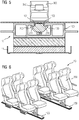
- the Figure 6 shows an embodiment for a rail vehicle 10, in which two mounting rails 100, for example the mounting rail 100 according Figure 1, 4th or 5 can be used to assemble vehicle seats 350.
- the vehicle seats 350 thus form vehicle components 300 according to Figure 5 that are attached to the mounting rails 100.
- a mounting method is described below by way of example, in which mounting rails 101 and 102, which correspond to mounting rail 100 according to FIG. 1, are fastened to a body-in-white section 11 of a rail vehicle 10.
- An example is used to explain in detail how a first mounting rail 101 can be connected to a second mounting rail 102 adjacent in the longitudinal direction of the rail.
- the first mounting rail 101 is first attached to the body-in-white section 11 of the rail vehicle 10; the adhesive layer 20, the foam material 30, the metal sheet 50 and the thick-film adhesive 40 are used, the function and arrangement of which is already in connection with the Figure 1 has been explained.
- an end-side interface section 170 of the first mounting rail 101 is preferably left unglued, so that the mounting rail 101 is separated from the body-in-white section 11 by means of an air gap LP.
- an adhesive layer 20 nor a foam material 30, a metal sheet 50 or a thick-layer adhesive 40 such as are used in the central region of the mounting rail 101 for fastening to the body-in-white 11.
- the interface section 170 is provided with four holes 171, which will enable the interface section 170 to be screwed, as will be explained in more detail below.
- the Figure 8 shows the first mounting rail 101 and a connecting plate 500 which has been pushed under the interface section 170 or into the air gap LP between the interface section 170 of the mounting rail 101 and the body-in-white section 11.
- connection plate 500 After the connection plate 500 has been installed, two rod elements 600 and 601 are inserted into the hollow chamber sections 120 and 121 of the mounting rail 101 (cf. Figure 8 ) inserted.
- the rod elements 600 and 601 each have four through holes 610, two of which, after the correct installation of the two rod elements 600 and 601, are each aligned with two holes 171 of the interface section 170 of the first mounting rail 101 (cf. Figure 9 ).
- a second mounting rail 102 which is for example connected to the mounting rail 100 according to FIG. Figure 4 or Figure 5 or can be identical to the first mounting rail 101, with its end-side interface section 170 pushed onto the two rod elements 600 and 601.
- the rod elements 600 and 601 are inserted into the Hollow chamber sections 120 and 121 of the second mounting rail 102 penetrate.
- the interface section 170 of the second mounting rail 102 is - just like that of the first mounting rail 101 - equipped with four holes 171 which, after the correct positioning of the second mounting rail 102 relative to the two rod elements 600 and 601, each have an associated through hole 610 of one of the two rod elements 600 and 601 s worn.
- FIG Figure 10 The two mounting rails 101 and 102 which are aligned relative to one another on the bodyshell 11 in the manner described are shown in FIG Figure 10 shown.
- the Figure 11 shows an example of how the two mounting rails 101 and 102 are screwed to the connecting plate 500 by means of screws 700.
- the connecting plate 500 is provided with threaded holes 501 (cf. Figure 8 ), which are aligned with the through holes 610 located above them in the two rod elements 600 and 601 and the holes 171 in the two interface sections 170 of the two mounting rails 101 and 102.
- the screws 700 are pushed through the holes 171 in the two interface sections 170 and through the through holes 610 in the rod elements 600 and 601 until they can be screwed into the threaded holes 501 in the connecting plate 500.
- the screws 700 are then screwed on, the screws 700 being screwed into the threaded holes 501 of the connecting plate 500, so that the two mounting rails 101 and 102 are screwed tightly to the rod elements 600 and 601 and also to the connecting plate 500.
- pins 750 preferably in the form of dowel pins, are inserted or pressed into corresponding pin holes 502 of the connecting plate 500, so that a further mechanical connection between the connecting plate 500 and the two mounting rails 101 and 102 is manufactured.
- the two interface sections 170 of the two mounting rails 101 and 102 are combined in the exemplary embodiment according to FIGS Figures 7 to 12 , so connected to the connecting plate 500 by a total of eight screws 700 and two pins 750.
- the rod elements 600 and 601 are clamped to the two mounting rails 101 and 102 and the connecting plate 500, which (in particular because of the closed contour of the hollow chamber sections 120 and 121) results in a particularly high mechanical stability of the connection between the two mounting rails 101 and 102 in the transverse direction of the rail is achieved.
- the two pins 750 ensure that particularly large longitudinal forces, which can occur, for example, in the event of temperature fluctuations due to different propagation constants of the material of the body of the rail vehicle 10 and the material of the two mounting rails 101 and 102, are particularly reliably ensured.
- the Figure 13 shows the fully assembled mounting rail 101 in a cross section along the section line XIII-XIII according to FIG. 12.
- the pin 750 can be seen, which establishes a mechanical connection between the connecting plate 500 and the mounting rail 101 lying above it.
- the two rod elements 600 and 601 can be seen, each corresponding to the hollow chamber sections 120 and 121 of the mounting rail 101 and to the hollow chamber sections 120 and 121 of the mounting rail 102 aligned in the longitudinal direction of the rail Figure 12 intervention.
- FIGS 14 and 15 show an embodiment of a connecting plate 500, as used to connect the two mounting rails 101 and 102 according to the Figures 7 to 12 can be used.
- Eight threaded holes 501 can be seen, which are suitable for screwing with the screws 700 Figure 11 or for screwing to the two mounting rails 101 and 102.
- two pin holes 502 can be seen, into which the pins 750 are located Figure 12 for connection to the mounting rail 101 or 102 located above each, insert, in particular, let in.
- the connecting parts of the rail connection are preferably made of steel, stainless steel, light metal, plastic and / or reinforced plastic.
Description
Die Erfindung bezieht sich auf Fahrzeuge, insbesondere Schienenfahrzeuge, mit einer Montageschiene, nach dem Oberbegriff von Anspruch 1 sowie auf ein Verfahren zum Montieren von Montageschienen nach dem Oberbegriff von Anspruch 10. Ein solches Fahrzeug bzw.ein solches Montageverfahren sind beispielsweise aus der
Zudem ist aus der
Bekannterweise können Fahrzeuge, wie Schienenfahrzeuge, mit Montageschienen, beispielsweise Fußbodenschienen, versehen werden, die flexible Anbindungspunkte zur Anbindung von Sitzen, Schränken oder sonstigen Anbauteilen oder Fahrzeugkomponenten bieten. Bei der Montage und Dimensionierung der Fußbodenschienen muss berücksichtigt werden, dass diese extrem hohe Kräfte übertragen bzw. halten können müssen.As is known, vehicles, such as rail vehicles, can be provided with mounting rails, for example floor rails, which offer flexible connection points for connecting seats, cabinets or other add-on parts or vehicle components. When installing and dimensioning the floor rails, it must be taken into account that they must be able to transmit or hold extremely high forces.
Der Erfindung liegt die Aufgabe zugrunde, ein Fahrzeug, insbesondere Schienenfahrzeug, mit einer besonders fest bzw. hoch belastbar montierten Montageschiene anzugeben.The invention is based on the object of specifying a vehicle, in particular a rail vehicle, with a mounting rail which is mounted in a particularly firm or highly loadable manner.
Diese Aufgabe wird erfindungsgemäß durch ein Fahrzeug mit den Merkmalen gemäß Patentanspruch 1 gelöst. Vorteilhafte Ausgestaltungen des erfindungsgemäßen Fahrzeugs sind in Unteransprüchen angegeben.This object is achieved according to the invention by a vehicle with the features according to claim 1. Advantageous embodiments of the vehicle according to the invention are specified in the subclaims.
Danach ist erfindungsgemäß vorgesehen, dass mit der Montageschiene - nachfolgend erste Montageschiene genannt - eine in Schienenlängsrichtung angrenzende zweite Montageschiene verbunden, insbesondere verschraubt und/oder verstiftet, ist.It is then provided according to the invention that with the mounting rail - hereinafter referred to as the first mounting rail - one in Rail longitudinal direction adjacent second mounting rail is connected, in particular screwed and / or pinned.
Ein wesentlicher Vorteil des erfindungsgemäßen Fahrzeugs ist darin zu sehen, dass durch das Verbinden der in Schienenlängsrichtung hintereinander angeordneten Montageschienen eine Kraftübertragung nicht nur mit dem Fahrzeugrohbau, sondern auch zwischen benachbarten Montageschienen, vorzugsweise sowohl in Schienenlängsrichtung als auch in Schienenquerrichtung, erreicht wird und damit die Stabilität der Anbindung der Montageschienen am Fahrzeug insgesamt - verglichen mit einer Montage ohne Verbindung der Montageschienen untereinander - signifikant erhöht wird.A significant advantage of the vehicle according to the invention can be seen in that, by connecting the mounting rails arranged one behind the other in the longitudinal direction of the rail, a power transmission not only with the vehicle body-in-white, but also between adjacent mounting rails, preferably both in the longitudinal direction and in the transverse direction of the rail, is achieved and thus the stability of the connection of the mounting rails to the vehicle as a whole - compared to mounting without connecting the mounting rails to one another - is significantly increased.
Zudem ist vorgesehen, dass jede der beiden Montageschienen jeweils einen Schnittstellenabschnitt mit zumindest einem Loch aufweist, durch das eine Schraube senkrecht zur Schienenlängsrichtung hindurchgeführt ist, wobei die Schraube den jeweiligen Schnittstellenabschnitt mit einer Verbindungsplatte verschraubt, die sich abschnittsweise unter der jeweiligen Montageschiene und abschnittsweise unter dem Schnittstellenabschnitt der benachbarten Montageschiene befindet.In addition, it is provided that each of the two mounting rails each has an interface section with at least one hole through which a screw is passed perpendicular to the longitudinal direction of the rail, the screw screwing the respective interface section to a connecting plate, which is located in sections under the respective mounting rail and in sections under the Interface section of the adjacent mounting rail is located.
Bezüglich der Ausgestaltung und Verbindung der Montageschienen wird es als vorteilhaft angesehen, wenn die Montageschienen jeweils durch ein Hohlkammerprofil gebildet sind oder ein solches umfassen, das zumindest einen Hohlkammerabschnitt mit - im Querschnitt gesehen - geschlossener Kontur aufweist, - in Schienenlängsrichtung gesehen - mindestens ein Stangenelement sowohl in den Hohlkammerabschnitt der ersten Montageschiene als auch in den Hohlkammerabschnitt der zweiten Montageschiene eingeführt ist und das in den Hohlkammerabschnitten befindliche Stangenelement mit den beiden Montageschienen verschraubt ist.With regard to the design and connection of the mounting rails, it is considered to be advantageous if the mounting rails are each formed by or comprise a hollow chamber profile that has at least one hollow chamber section with a closed contour, as seen in cross section, and at least one rod element, as seen in the longitudinal direction of the rail is inserted into the hollow chamber section of the first mounting rail and into the hollow chamber section of the second mounting rail and the rod element located in the hollow chamber sections is screwed to the two mounting rails.
Vorzugsweise ist das in den Hohlkammerabschnitten befindliche Stangenelement auch mit der Verbindungsplatte verschraubt.The rod element located in the hollow chamber sections is preferably also screwed to the connecting plate.
Besonders vorteilhaft ist es, wenn die erste Montageschiene mindestens zwei in Schienenlängsrichtung parallel angeordnete Hohlkammerabschnitte aufweist, von denen ein erster Hohlkammerabschnitt mit einem ersten Hohlkammerabschnitt der zweiten Montageschiene fluchtet und von denen ein zweiter Hohlkammerabschnitt mit einem zweiten Hohlkammerabschnitt der zweiten Montageschiene fluchtet, ein erstes Stangenelement sich in die beiden ersten Hohlkammerabschnitte der beiden Montageschienen erstreckt und dort verschraubt ist und ein zweites Stangenelement sich in die beiden zweiten Hohlkammerabschnitte der beiden Montageschienen erstreckt und dort verschraubt ist.It is particularly advantageous if the first mounting rail has at least two hollow chamber sections arranged in parallel in the longitudinal direction of the rail, of which a first hollow chamber section is flush with a first hollow chamber section of the second mounting rail and of which a second hollow chamber section is flush with a second hollow chamber section of the second mounting rail, a first rod element into the first two hollow sections of the two mounting rails extends and is screwed there and a second rod element extends into the two second hollow chamber sections of the two mounting rails and is screwed there.
Bezüglich der bereits erwähnten Verstiftung der Montageschienen wird es als vorteilhaft angesehen, wenn die beiden Montageschienen jeweils mit mindestens einem Stift, vorzugsweise selbstschneidendem Passstift, mit der Verbindungsplatte verstiftet sind.With regard to the already mentioned pinning of the mounting rails, it is considered advantageous if the two mounting rails are each pinned to the connecting plate with at least one pin, preferably a self-tapping dowel pin.
Vorzugsweise ist der Durchmesser und/oder Querschnitt der Stifte größer als der Durchmesser und/oder Querschnitt der Schrauben.The diameter and / or cross section of the pins is preferably larger than the diameter and / or cross section of the screws.
Mit Blick auf eine Anbindung von Fahrzeugkomponenten im Fahrzeug wird es als vorteilhaft angesehen, wenn an zumindest einer der Montageschienen eine Fahrzeugkomponente mittels eines Nutensteines, der sich in einem Nutenaufnahmeabschnitt der Montageschiene befindet, montiert ist.With regard to a connection of vehicle components in the vehicle, it is considered advantageous if a vehicle component is mounted on at least one of the mounting rails by means of a slot nut, which is located in a slot receiving section of the mounting rail.
Für einen festen Sitz des Nutensteins ist es vorteilhaft, wenn der Nutenstein zumindest einen Formschlussabschnitt aufweist, in den ein Schienenabschnitt der Montageschiene eingreift.For a tight fit of the sliding block, it is advantageous if the sliding block has at least one form-locking section, in which a rail section of the mounting rail engages.
Um einen besonders festen Sitz des Nutensteins in der Montageschiene zu gewährleisten, wird es als vorteilhaft angesehen, wenn der Formschlussabschnitt des Nutensteins rinnenförmig ist und der darin eingreifende Schienenabschnitt der Montageschiene durch einen in den Nutenaufnahmeabschnitt des Nutensteins hineinragenden Vorsprung gebildet ist.In order to ensure a particularly tight fit of the sliding block in the mounting rail, it is considered advantageous if the form-fitting section of the sliding block is trough-shaped and the rail section of the mounting rail engaging therein is formed by a projection protruding into the groove receiving section of the sliding block.
Eine besonders einfache Montage lässt sich erreichen, wenn der Nutenstein und der Nutenaufnahmeabschnitt der Montageschiene derart dimensioniert und geformt sind, dass der Nutenstein senkrecht zur Schienenlängsrichtung durch einen sich in Schienenlängsrichtung erstreckenden Schlitz in den Nutenaufnahmeabschnitt der Montageschiene eingeführt und dort durch Drehen oder Schwenken in seine Montageendposition gebracht werden kann.A particularly simple assembly can be achieved if the slot nut and the slot receiving section of the mounting rail are dimensioned and shaped such that the slot nut is perpendicular to the longitudinal direction of the rail through a slot extending in the longitudinal direction of the slot in the slot receiving section the mounting rail and can be brought to its final assembly position by turning or swiveling.
Die Erfindung bezieht sich darüber hinaus auf ein Verfahren zum Montieren einer Montageschiene in einem Fahrzeug, insbesondere Schienenfahrzeug. Erfindungsgemäß ist bezüglich eines solchen Verfahrens vorgesehen, dass die Montageschiene, nachfolgend erste Montageschiene genannt, fahrzeugseitig montiert wird und nachfolgend eine zweite Montageschiene - in Schienenlängsrichtung angrenzend - mit der ersten Montageschiene verbunden, insbesondere verschraubt und/oder verstiftet, wird.The invention also relates to a method for mounting a mounting rail in a vehicle, in particular a rail vehicle. According to the invention, with respect to such a method, it is provided that the mounting rail, hereinafter referred to as the first mounting rail, is mounted on the vehicle side and then a second mounting rail - adjacent in the longitudinal direction of the rail - is connected, in particular screwed and / or pinned, to the first mounting rail.
Bei diesem Verfahren ist außerdem vorgesehen, dass vor, während oder nach der Montage der ersten Montageschiene eine Verbindungsplatte abschnittsweise unter der ersten Montageschiene angeordnet wird, die zweite Montageschiene abschnittsweise auf einem unter der ersten Montageschiene herausragenden Abschnitt der Verbindungsplatte aufgesetzt wird, vor, während oder nach dem Aufsetzen der zweiten Montageschiene eine Schraube durch ein Loch in einem Schnittstellenabschnitt der ersten Montageschiene senkrecht zur Schienenlängsrichtung hindurchgeführt wird und mit der Verbindungsplatte verschraubt wird und eine Schraube durch ein Loch in einem Schnittstellenabschnitt der zweiten Montageschiene senkrecht zur Schienenlängsrichtung hindurchgeführt wird und mit der Verbindungsplatte verschraubt wird.In this method it is also provided that before, during or after the assembly of the first mounting rail, a connecting plate is arranged in sections under the first mounting rail, the second mounting rail is placed in sections on a section of the connecting plate protruding under the first mounting rail, before, during or after after placing the second mounting rail, a screw is passed through a hole in an interface section of the first mounting rail perpendicular to the longitudinal direction of the rail and is screwed to the connecting plate, and a screw is passed through a hole in an interface section of the second mounting rail perpendicular to the longitudinal direction of the rail and is screwed to the connecting plate .
Zusätzlich kann vorgesehen sein, dass die Montageschienen jeweils durch ein Hohlkammerprofil mit zumindest einem Hohlkammerabschnitt gebildet sind oder ein solches umfassen, vor, während oder nach der Montage der ersten Montageschiene - in Schienenlängsrichtung gesehen - ein Stangenelement in den oder einen der Hohlkammerabschnitte der ersten Montageschiene eingeschoben wird, bei der Montage der zweiten Montageschiene ein Hohlkammerabschnitt der zweiten Montageschiene mit dem mit dem Stangenelement versehenen Hohlkammerabschnitt der ersten Montageschiene fluchtend ausgerichtet und auf den aus der ersten Montageschiene herausragenden Stangenabschnitt des Stangenelements aufgeschoben wird und das in den zwei fluchtenden Hohlkammerabschnitten befindliche Stangenelement mit den beiden Montageschienen und/oder der Verbindungsplatte verschraubt wird.In addition, it can be provided that the mounting rails are each formed by or encompassing a hollow chamber profile with at least one hollow chamber section, before, during or after the mounting of the first mounting rail - as seen in the longitudinal direction of the rail - a rod element is inserted into or one of the hollow chamber sections of the first mounting rail becomes a hollow section of the second mounting rail when mounting the second mounting rail aligned with the hollow chamber section of the first mounting rail provided with the rod element and pushed onto the rod section of the rod element protruding from the first mounting rail and the rod element located in the two aligned hollow chamber sections is screwed to the two mounting rails and / or the connecting plate.
Auch ist es vorteilhaft, wenn die beiden Montageschienen jeweils mit mindestens einem Stift, vorzugsweise selbstschneidendem Passstift, mit der Verbindungsplatte verstiftet werden.It is also advantageous if the two mounting rails are each pinned to the connecting plate with at least one pin, preferably a self-tapping dowel pin.
Die Erfindung bezieht sich darüber hinaus auf einen Nutenstein, der zur Montage in einer Montagschiene, wie sie bei dem erfindungsgemäßen Fahrzeug vorgesehen ist, geeignet ist.The invention also relates to a sliding block which is suitable for mounting in a mounting rail, as is provided in the vehicle according to the invention.
Als vorteilhaft wird es angesehen, wenn der Nutenstein zumindest einen Formschlussabschnitt aufweist, in den ein Schienenabschnitt einer Montageschiene, insbesondere unter Bildung eines Formschlusses, eingreifen kann.It is considered to be advantageous if the sliding block has at least one form-fitting section, into which a rail section of an assembly rail can engage, in particular to form a form-fitting connection.
Der Formschlussabschnitt des Nutensteins ist vorzugsweise rinnenförmig, so dass ein darin eingreifender Schienenabschnitt der Montageschiene durch einen in den Aufnahmeraum des Nutensteins hineinragenden Vorsprung gebildet sein kann.The form-fitting section of the sliding block is preferably channel-shaped, so that a rail section of the mounting rail engaging therein can be formed by a projection protruding into the receiving space of the sliding block.
Auch wird es als vorteilhaft angesehen, wenn - alternativ oder zusätzlich - der Nutenstein bezüglich des für ihn vorgesehenen Nutenaufnahmeabschnitts der Montageschiene derart dimensioniert und geformt ist, dass er senkrecht zur Schienenlängsrichtung durch einen sich in Schienenlängsrichtung erstreckenden Schlitz in den Nutenaufnahmeabschnitt der Montageschiene eingeführt und dort durch Drehen oder Schwenken in seine Montageendposition gebracht werden kann.It is also considered advantageous if - alternatively or additionally - the slot nut is dimensioned and shaped with respect to the slot receiving section of the mounting rail provided for it in such a way that it is inserted perpendicularly to the longitudinal direction of the rail through a slot extending in the longitudinal direction of the slot into the slot receiving section of the mounting rail and there through Rotation or swiveling can be brought into its final assembly position.
Die Erfindung wird nachfolgend anhand von Ausführungsbeispielen näher erläutert; dabei zeigen beispielhaft
- Figur 1
- in einem Querschnitt ein Ausführungsbeispiel für eine Montageschiene, die auf einem Rohbauabschnitt eines Schienenfahrzeugs montiert ist,
- Figur 2
- ein Ausführungsbeispiel für einen Nutenstein, der in einem Nutenaufnahmeabschnitt der Montageschiene gemäß
Figur 1 montierbar ist, - Figur 3
- den Nutenstein gemäß
Figur 2 im Querschnitt, - Figur 4
- die Montage des Nutensteins gemäß den
Figuren 2 und 3 in der Montageschiene gemäßFigur 1 , - Figur 5
- beispielhaft die Montage einer Fahrzeugkomponente an dem Nutenstein gemäß den
Figuren 2 bis 4 bzw. der Montageschiene gemäß denFiguren 1 und 4 , - Figur 6
- den Innenraum eines Schienenfahrzeugs, bei dem Fahrzeugsitze auf Montageschienen gemäß
Figur 1 montiert sind, - Fig. 7-12
- ein Ausführungsbeispiel für ein erfindungsgemäßes Montageverfahren zum Hintereinandermontieren von Montageschienen wie beispielsweise der Montageschiene gemäß
Figur 1 , - Figur 13
- die gemäß den
Figuren 7 bis 12 montierten Montageschienen in einem Querschnitt und - Fig. 14-15
- in dreidimensionaler Darstellung schräg von der Seite ein Ausführungsbeispiel für eine Verbindungsplatte, die zum Verbinden zweier benachbarter Montageschienen, wie beispielsweise der Montageschiene gemäß
Figur 1 , geeignet ist.
- Figure 1
- in a cross section an embodiment of a mounting rail which is mounted on a body-in-white section of a rail vehicle,
- Figure 2
- an embodiment of a sliding block which according to in a groove receiving portion of the mounting rail
Figure 1 is mountable, - Figure 3
- according to the sliding block
Figure 2 in cross section, - Figure 4
- the assembly of the sliding block according to the
Figures 2 and 3 in the mounting rail according toFigure 1 , - Figure 5
- exemplary the assembly of a vehicle component on the sliding block according to the
Figures 2 to 4 or the mounting rail according toFigures 1 and 4 , - Figure 6
- the interior of a rail vehicle, according to the vehicle seats on mounting rails
Figure 1 are mounted, - Fig. 7-12
- an embodiment of an assembly method according to the invention for mounting one behind the other mounting rails such as the mounting rail according to
Figure 1 , - Figure 13
- which according to the
Figures 7 to 12 assembled mounting rails in a cross section and - Fig. 14-15
- in a three-dimensional representation obliquely from the side an embodiment for a connecting plate, which for connecting two adjacent mounting rails, such as the mounting rail according
Figure 1 , suitable is.
In den Figuren werden der Übersicht halber für identische oder vergleichbare Komponenten stets dieselben Bezugszeichen verwendet.For the sake of clarity, the same reference numbers are always used in the figures for identical or comparable components.
Die
Die Klebeschicht 20, das Schaummaterial 30, das Metallblech 50 sowie der Dickschichtkleber 40 - oder alternativ die Klebeschicht 20, das Schaummaterial 30 und das Metallblech 50 - können mit der Montageschiene eine vorgefertigte Einheit, sozusagen eine Montageschieneneinheit, bilden, die in vorgefertigter Form auf dem Rohbauabschnitt 11 aufgeklebt wird.The
Bei der Montageschiene 100 handelt es sich vorzugsweise um ein Strangpressprofilbauteil (insbesondere Aluminiumstrangpressprofilbauteil), dessen Strangpressrichtung bzw. Längsrichtung bei der Darstellung gemäß
An die beiden Fußbodenabschnitte 110 und 111 grenzen bei dem Ausführungsbeispiel gemäß
Zwischen den beiden Hohlkammerabschnitten 120 und 121 befindet sich ein Nutenaufnahmeabschnitt 130, der von außen durch einen Schlitz 140 zugänglich ist. Durch den Schlitz 140 kann von außen ein in der
Im Randbereich des Schlitzes 140 weist die Montageschiene 100 - im Querschnitt gesehen - zwei Vorsprünge 150 und 151 auf, die sich in Richtung in den Nutenaufnahmeabschnitt 130 hinein erstrecken. Die Ausrichtung der beiden Vorsprünge 150 und 151 ist - nach Montage der Montageschiene 100 auf dem Rohbauabschnitt 11 - vorzugsweise vertikal.In the edge region of the
Die
Die
Die
Es lässt sich in der
Die
Die
Die
Die
Im Zusammenhang mit den
Wie
Bei der Montage der ersten Montageschiene 101 auf dem Rohbauabschnitt 11 wird vorzugsweise ein endseitiger Schnittstellenabschnitt 170 der ersten Montageschiene 101 unverklebt gelassen, so dass die Montageschiene 101 von dem Rohbauabschnitt 11 mittels eines Luftspalts LP getrennt ist. Mit anderen Worten befinden sich bei der Darstellung gemäß
Der Schnittstellenabschnitt 170 ist mit vier Löchern 171 versehen, die ein Verschrauben des Schnittstellenabschnitts 170 ermöglichen werden, wie weiter unten noch näher erläutert wird.The
Die
Nach der Montage der Verbindungsplatte 500 werden zwei Stangenelemente 600 und 601 in die Hohlkammerabschnitte 120 und 121 der Montageschiene 101 (vgl.
Nach der Montage der Verbindungsplatte 500 sowie der beiden Stangenelemente 600 und 601 wird eine zweite Montageschiene 102, die beispielsweise mit der Montageschiene 100 gemäß Figur 1,
Der Schnittstellenabschnitt 170 der zweiten Montageschiene 102 ist - genauso wie der der ersten Montageschiene 101 - mit vier Löchern 171 ausgestattet, die nach korrekter Positionierung der zweiten Montageschiene 102 relativ zu den beiden Stangenelementen 600 und 601 jeweils mit einem zugeordneten Durchgangsloch 610 eines der beiden Stangenelemente 600 und 601 fluchten.The
Die in der beschriebenen Weise relativ zueinander auf dem Rohbau 11 ausgerichteten zwei Montageschienen 101 und 102 sind in der
Die
Im Rahmen des Verschraubens werden mit anderen Worten also die Schrauben 700 durch die Löcher 171 in den beiden Schnittstellenabschnitten 170 sowie durch die Durchgangslöcher 610 in den Stangenelementen 600 bzw. 601 durchgeschoben, bis sie mit den Gewindelöchern 501 in der Verbindungsplatte 500 verschraubt werden können. Anschließend erfolgt das Verschrauben der Schrauben 700, wobei die Schrauben 700 in die Gewindelöcher 501 der Verbindungsplatte 500 eingeschraubt werden, so dass die beiden Montageschienen 101 und 102 sowohl mit den Stangenelementen 600 und 601 als auch mit der Verbindungsplatte 500 fest verschraubt werden.In other words, as part of the screwing, the
Nach dem Verschrauben der beiden Montageschienen 101 und 102 werden Stifte 750, vorzugsweise in Form von Passstiften, in korrespondierende Stiftlöcher 502 der Verbindungsplatte 500 eingesetzt bzw. eingedrückt bzw. eingeschlagen, so dass eine weitere mechanische Verbindung zwischen der Verbindungsplatte 500 und den beiden Montageschienen 101 und 102 hergestellt wird.After the two mounting
Zusammengefasst werden die beiden Schnittstellenabschnitte 170 der beiden Montageschienen 101 und 102 bei dem Ausführungsbeispiel gemäß den
Durch die beiden Stifte 750 wird die Übertragung auch besonders großer Längskräfte, die beispielsweise bei Temperaturschwankungen aufgrund unterschiedlicher Ausbreitungskonstanten des Materials des Wagenkastens des Schienenfahrzeugs 10 und des Materials der beiden Montageschienen 101 und 102 auftreten können, besonders sicher gewährleistet.The two
Die
Auch sieht man in der
Die
Im Übrigen sei auf die obigen Erläuterungen im Zusammenhang mit den
Zusammengefasst ermöglicht die im Zusammenhang mit den
Die Verbindungsteile der Schienenanbindung, also die Stangenelemente 600 und 601, die Verbindungsplatte 500, die Schrauben 700 und die Stifte 750, bestehen vorzugsweise aus Stahl, Edelstahl, Leichtmetall, Kunststoff und/oder verstärktem Kunststoff.The connecting parts of the rail connection, that is to say the
Obwohl die Erfindung im Detail durch bevorzugte Ausführungsbeispiele näher illustriert und beschrieben wurde, so ist die Erfindung nicht durch die offenbarten Beispiele eingeschränkt und andere Variationen können vom Fachmann hieraus abgeleitet werden, ohne den Schutzumfang der Erfindung zu verlassen.Although the invention has been illustrated and described in detail by means of preferred exemplary embodiments, the invention is not restricted by the disclosed examples and other variations can be derived therefrom by those skilled in the art without departing from the scope of the invention.
Claims (12)
- Vehicle, in particular rail vehicle (10), having a mounting rail (100, 101, 102), wherein the mounting rail - termed first mounting rail (101) below - has a second mounting rail (102) adjoining in the rail longitudinal direction connected thereto, in particular by screwing and/or pinning,
characterized in that- each of the two mounting rails (100, 101, 102) has a respective interface portion (170) with at least one hole (171) through which a screw (700) is guided perpendicularly to the rail longitudinal direction,- wherein the screw (700) screws the respective interface portion (170) to a connecting plate (500) which is situated in certain portions below the respective mounting rail (100, 101, 102) and in certain portions below the interface portion (170) of the adjacent mounting rail (100, 101, 102). - Vehicle according to Claim 1,
characterized in that- the mounting rails (101, 102) are each formed by a hollow-chamber profile or comprise such a profile, which has at least one hollow-chamber portion (170) with - as seen in cross section - a closed contour,- - as seen in the rail longitudinal direction - at least one rod element (600, 601) is inserted both into the hollow-chamber portion (170) of the first mounting rail (101) and into the hollow-chamber portion (170) of the second mounting rail (102), and- the rod element (600, 601) situated in the hollow-chamber portions (170) is screwed to the two mounting rails (101, 102) . - Vehicle according to Claim 2,
characterized in that
the rod element (600, 601) situated in the hollow-chamber portions (170) is also screwed to the connecting plate (500) . - Vehicle according to one of the preceding claims,
characterized in that
the two mounting rails (100, 101, 102) are each pinned to the connecting plate (500) by at least one pin (750), preferably a self-cutting fitting pin. - Vehicle according to one of the preceding claims,
characterized in that
a vehicle component is mounted on at least one of the mounting rails (100, 101, 102) by means of a grooved block (200) which is situated in a grooved receiving portion (130) of the mounting rail (100, 101, 102). - Vehicle according to Claim 5,
characterized in that
the grooved block (200) has at least one form-fitting portion (210, 211) in which a rail portion of the mounting rail (100, 101, 102) engages. - Vehicle according to Claim 6,
characterized in that- the form-fitting portion (210, 211) of the grooved block (200) is channel-shaped, and- the rail portion, which engages therein, of the mounting rail (100, 101, 102) is formed by a projection (150, 151) which protrudes into the grooved receiving portion (130) of the grooved block (200). - Vehicle according to one of Claims 1 to 7,
characterized in that- a vehicle component is mounted on the mounting rail (100, 101, 102) by means of a grooved block,- wherein the grooved block (200) has at least one form-fitting portion (210, 211) in which a rail portion of the mounting rail (100, 101, 102) engages. - Vehicle according to Claim 8,
characterized in that
the form-fitting portion (210, 211) of the grooved block (200) is channel-shaped, and the rail portion, which engages therein, of the mounting rail (100, 101, 102) is formed by a projection (150, 151) which protrudes into the receiving space of the grooved block (200). - Method for mounting a mounting rail in a vehicle, in particular rail vehicle (10), wherein the mounting rail, termed first mounting rail (101) below, is mounted on the vehicle and then a second mounting rail (102) - adjoining in the rail longitudinal direction - is connected, in particular screwed and/or pinned, to the first mounting rail (101),
characterized in that- before, during or after mounting the first mounting rail (101), a connecting plate (500) is arranged in certain portions below the first mounting rail (101),- the second mounting rail (102) is placed in certain portions on a portion of the connecting plate (500) that projects below the first mounting rail (101),- before, during or after placing the second mounting rail (102), a screw (700) is guided through a hole (171) in an interface portion (170) of the first mounting rail (101) perpendicularly to the rail longitudinal direction and is screwed to the connecting plate (500), and- a screw (700) is guided through a hole (171) in an interface portion (170) of the second mounting rail (102) perpendicularly to the rail longitudinal direction and is screwed to the connecting plate (500). - Method according to one of the preceding Claims 9 and 10,
characterized in that- the mounting rails (101, 102) are each formed by a hollow-chamber profile with at least one hollow-chamber portion (170) or comprise such a profile,- before, during or after mounting the first mounting rail (101), a rod element (600, 601) is - as seen in the rail longitudinal direction - inserted into the or one of the hollow-chamber portions (170) of the first mounting rail (101),- during the mounting of the second mounting rail (102), a hollow-chamber portion (170) of the second mounting rail (102) is oriented in alignment with the hollow-chamber portion (170), provided with the rod element (600, 601), of the mounting rail (101) and pushed onto the rod portion of the rod element (600, 601) that projects from the first mounting rail (101), and- the rod element (600, 601) situated in the two aligned hollow-chamber portions (170) is screwed to the two mounting rails (101, 102) and/or the connecting plate (500) . - Method according to one of the preceding Claims 1 to 11,
characterized in that
the two mounting rails (100, 101, 102) are each pinned to the connecting plate (500) by at least one pin (750), preferably a self-cutting fitting pin.
Priority Applications (2)
| Application Number | Priority Date | Filing Date | Title |
|---|---|---|---|
| EP18000334.5A EP3388302B1 (en) | 2014-07-09 | 2015-07-01 | Vehicle, especially railway vehicle, with an assembly rail |
| PL15733714T PL3140174T3 (en) | 2014-07-09 | 2015-07-01 | Vehicle, in particular rail vehicle, with a mounting rail |
Applications Claiming Priority (2)
| Application Number | Priority Date | Filing Date | Title |
|---|---|---|---|
| DE102014213365.3A DE102014213365A1 (en) | 2014-07-09 | 2014-07-09 | Vehicle, in particular rail vehicle, with a mounting rail |
| PCT/EP2015/064920 WO2016005234A1 (en) | 2014-07-09 | 2015-07-01 | Vehicle, in particular rail vehicle, with a mounting rail |
Related Child Applications (2)
| Application Number | Title | Priority Date | Filing Date |
|---|---|---|---|
| EP18000334.5A Division EP3388302B1 (en) | 2014-07-09 | 2015-07-01 | Vehicle, especially railway vehicle, with an assembly rail |
| EP18000334.5A Division-Into EP3388302B1 (en) | 2014-07-09 | 2015-07-01 | Vehicle, especially railway vehicle, with an assembly rail |
Publications (2)
| Publication Number | Publication Date |
|---|---|
| EP3140174A1 EP3140174A1 (en) | 2017-03-15 |
| EP3140174B1 true EP3140174B1 (en) | 2020-03-11 |
Family
ID=53502664
Family Applications (2)
| Application Number | Title | Priority Date | Filing Date |
|---|---|---|---|
| EP15733714.8A Active EP3140174B1 (en) | 2014-07-09 | 2015-07-01 | Vehicle, in particular rail vehicle, with a mounting rail |
| EP18000334.5A Active EP3388302B1 (en) | 2014-07-09 | 2015-07-01 | Vehicle, especially railway vehicle, with an assembly rail |
Family Applications After (1)
| Application Number | Title | Priority Date | Filing Date |
|---|---|---|---|
| EP18000334.5A Active EP3388302B1 (en) | 2014-07-09 | 2015-07-01 | Vehicle, especially railway vehicle, with an assembly rail |
Country Status (9)
| Country | Link |
|---|---|
| EP (2) | EP3140174B1 (en) |
| CN (1) | CN207523701U (en) |
| DE (1) | DE102014213365A1 (en) |
| DK (1) | DK3140174T3 (en) |
| ES (2) | ES2787649T3 (en) |
| PL (1) | PL3140174T3 (en) |
| PT (1) | PT3140174T (en) |
| RU (1) | RU179907U1 (en) |
| WO (1) | WO2016005234A1 (en) |
Families Citing this family (2)
| Publication number | Priority date | Publication date | Assignee | Title |
|---|---|---|---|---|
| AT516921B1 (en) * | 2015-03-10 | 2017-03-15 | Siemens Ag Oesterreich | Arrangement for fastening a coupling element to a car body of a vehicle |
| DE102017213552A1 (en) * | 2017-08-04 | 2019-02-07 | Siemens Aktiengesellschaft | Slot nut, rail vehicle and use and manufacturing method of a sliding block |
Family Cites Families (11)
| Publication number | Priority date | Publication date | Assignee | Title |
|---|---|---|---|---|
| DE3115699A1 (en) * | 1981-04-18 | 1982-10-28 | Messerschmitt-Bölkow-Blohm GmbH, 8000 München | TRAINING OF THE FLOOR AREA OF VEHICLES WITH FASTENING DEVICES |
| DE29500474U1 (en) * | 1995-01-13 | 1995-02-23 | Karmann Rheine Gmbh & Co Kg | Device for sliding attachment of seats, benches or the like Furnishing parts on the body floor of vehicles for the transportation of passengers |
| DE29718615U1 (en) * | 1997-10-21 | 1998-03-05 | Profitec | Channel unit |
| DE20106841U1 (en) * | 2001-04-19 | 2001-08-09 | Atecs Mannesmann Ag | Rail for a monorail trolley |
| DE10159676A1 (en) * | 2001-12-05 | 2003-06-26 | Vogel Ind Gmbh | Ground reinforcement for passenger vehicles |
| FR2905739B1 (en) * | 2006-09-08 | 2008-11-07 | Airbus France Sas | PANEL ASSEMBLY AND METHOD OF MOUNTING PANEL ASSEMBLY |
| RU76617U1 (en) * | 2008-03-13 | 2008-09-27 | Открытое Акционерное Общество "Дизельный Завод" | UNIVERSAL Gondola car frame with hatchways in the body floor |
| DE102008048608B4 (en) * | 2008-09-23 | 2014-02-20 | Johannes Wißmann | Floor construction for rail vehicles |
| DE102008058633A1 (en) * | 2008-11-24 | 2010-05-27 | Siemens Aktiengesellschaft | Floor system for a passenger transport vehicle, in particular rail vehicle |
| DE102011075825B4 (en) * | 2011-05-13 | 2014-09-18 | Siemens Aktiengesellschaft | Fastening device for seats in rail vehicles |
| PL2570322T3 (en) * | 2011-09-14 | 2015-06-30 | Bombardier Transp Gmbh | Holder element for constructing a floor of a rail vehicle car, floor of a rail vehicle car and rail vehicle car |
-
2014
- 2014-07-09 DE DE102014213365.3A patent/DE102014213365A1/en not_active Ceased
-
2015
- 2015-07-01 WO PCT/EP2015/064920 patent/WO2016005234A1/en active Application Filing
- 2015-07-01 ES ES15733714T patent/ES2787649T3/en active Active
- 2015-07-01 PT PT157337148T patent/PT3140174T/en unknown
- 2015-07-01 ES ES18000334T patent/ES2874324T3/en active Active
- 2015-07-01 PL PL15733714T patent/PL3140174T3/en unknown
- 2015-07-01 EP EP15733714.8A patent/EP3140174B1/en active Active
- 2015-07-01 DK DK15733714.8T patent/DK3140174T3/en active
- 2015-07-01 CN CN201590000801.6U patent/CN207523701U/en active Active
- 2015-07-01 EP EP18000334.5A patent/EP3388302B1/en active Active
- 2015-07-01 RU RU2017103972U patent/RU179907U1/en active
Non-Patent Citations (1)
| Title |
|---|
| None * |
Also Published As
| Publication number | Publication date |
|---|---|
| ES2787649T3 (en) | 2020-10-16 |
| ES2874324T3 (en) | 2021-11-04 |
| EP3388302B1 (en) | 2021-03-03 |
| EP3388302A1 (en) | 2018-10-17 |
| WO2016005234A1 (en) | 2016-01-14 |
| DE102014213365A1 (en) | 2016-01-14 |
| PL3140174T3 (en) | 2020-08-10 |
| EP3140174A1 (en) | 2017-03-15 |
| PT3140174T (en) | 2020-04-01 |
| RU179907U1 (en) | 2018-05-28 |
| CN207523701U (en) | 2018-06-22 |
| DK3140174T3 (en) | 2020-05-18 |
Similar Documents
| Publication | Publication Date | Title |
|---|---|---|
| DE102015114983A1 (en) | Roof support structure | |
| DE102012022876B4 (en) | Hollow profile with a reinforcing element | |
| EP1711376A1 (en) | Metal housing | |
| DE102016124078B3 (en) | Connecting arrangement for the connection of two control cabinet frame racks | |
| EP3140174B1 (en) | Vehicle, in particular rail vehicle, with a mounting rail | |
| DE102019101451A1 (en) | Profile arrangement | |
| EP2946972B1 (en) | Fastening system for internal device elements of commercial vehicles | |
| EP2868544B1 (en) | Fastening device for a transition profile in a railway vehicle, construction kit for a fastening device and method for fastening a transition profile | |
| DE102013225173A1 (en) | Mounting profile for plate-shaped modules | |
| DE202015005659U1 (en) | Profile system for forming a sub-frame for receiving floorboards and rail | |
| DE102013205995A1 (en) | Fastening arrangement for an interior trim element on the body of a vehicle | |
| DE102016000948A1 (en) | Fastening arrangement of a front cross member to an energy absorption element of a longitudinal member of a motor vehicle body | |
| DE102014213662A1 (en) | Arrangement and method for attaching trim parts to a substructure | |
| DE202014000971U1 (en) | Profile system for glazing | |
| DE102013100308A1 (en) | Bar fitting for a window or a door | |
| EP3934022A1 (en) | Roof antenna | |
| DE102016015791A1 (en) | Connecting arrangement for the connection of two control cabinet frame racks | |
| DE102023122136B3 (en) | Adapter component and use of an adapter component | |
| DE102021115852B4 (en) | Mounting arrangement for the interior of a switch cabinet housing | |
| EP2966307A1 (en) | Assembly and method for fixing cladding parts to a substructure | |
| DE102016124949B4 (en) | Adapter device for a sliding door system and sliding door system | |
| DE102012007233A1 (en) | Fastening arrangement for energy absorption element at longitudinal carrier of motor vehicle, particularly passenger car, has connecting unit with connecting elements in plug connection area | |
| DE102015203602A1 (en) | Adjustment element for positioning a component | |
| DE102015207722B4 (en) | Fairing part of a motorcycle or scooter as well as fairing unit consisting of several fairing parts | |
| DE102013114443A1 (en) | Floor profile for attachment of vehicle equipment in vehicles |
Legal Events
| Date | Code | Title | Description |
|---|---|---|---|
| STAA | Information on the status of an ep patent application or granted ep patent |
Free format text: STATUS: THE INTERNATIONAL PUBLICATION HAS BEEN MADE |
|
| PUAI | Public reference made under article 153(3) epc to a published international application that has entered the european phase |
Free format text: ORIGINAL CODE: 0009012 |
|
| STAA | Information on the status of an ep patent application or granted ep patent |
Free format text: STATUS: REQUEST FOR EXAMINATION WAS MADE |
|
| 17P | Request for examination filed |
Effective date: 20161206 |
|
| AK | Designated contracting states |
Kind code of ref document: A1 Designated state(s): AL AT BE BG CH CY CZ DE DK EE ES FI FR GB GR HR HU IE IS IT LI LT LU LV MC MK MT NL NO PL PT RO RS SE SI SK SM TR |
|
| AX | Request for extension of the european patent |
Extension state: BA ME |
|
| RAP1 | Party data changed (applicant data changed or rights of an application transferred) |
Owner name: SIEMENS AKTIENGESELLSCHAFT |
|
| DAV | Request for validation of the european patent (deleted) | ||
| DAX | Request for extension of the european patent (deleted) | ||
| RAP1 | Party data changed (applicant data changed or rights of an application transferred) |
Owner name: SIEMENS MOBILITY GMBH |
|
| GRAP | Despatch of communication of intention to grant a patent |
Free format text: ORIGINAL CODE: EPIDOSNIGR1 |
|
| STAA | Information on the status of an ep patent application or granted ep patent |
Free format text: STATUS: GRANT OF PATENT IS INTENDED |
|
| INTG | Intention to grant announced |
Effective date: 20191111 |
|
| RIN1 | Information on inventor provided before grant (corrected) |
Inventor name: SOBOLEWSKI, THOMAS Inventor name: LI, XIAOMENG Inventor name: KIESEL, MICHAEL Inventor name: HESTERBERG, JOSHUA |
|
| GRAS | Grant fee paid |
Free format text: ORIGINAL CODE: EPIDOSNIGR3 |
|
| GRAA | (expected) grant |
Free format text: ORIGINAL CODE: 0009210 |
|
| STAA | Information on the status of an ep patent application or granted ep patent |
Free format text: STATUS: THE PATENT HAS BEEN GRANTED |
|
| AK | Designated contracting states |
Kind code of ref document: B1 Designated state(s): AL AT BE BG CH CY CZ DE DK EE ES FI FR GB GR HR HU IE IS IT LI LT LU LV MC MK MT NL NO PL PT RO RS SE SI SK SM TR |
|
| REG | Reference to a national code |
Ref country code: GB Ref legal event code: FG4D Free format text: NOT ENGLISH |
|
| REG | Reference to a national code |
Ref country code: CH Ref legal event code: EP Ref country code: CH Ref legal event code: NV Representative=s name: VALIPAT S.A. C/O BOVARD SA NEUCHATEL, CH |
|
| REG | Reference to a national code |
Ref country code: AT Ref legal event code: REF Ref document number: 1242785 Country of ref document: AT Kind code of ref document: T Effective date: 20200315 |
|
| REG | Reference to a national code |
Ref country code: IE Ref legal event code: FG4D Free format text: LANGUAGE OF EP DOCUMENT: GERMAN Ref country code: PT Ref legal event code: SC4A Ref document number: 3140174 Country of ref document: PT Date of ref document: 20200401 Kind code of ref document: T Free format text: AVAILABILITY OF NATIONAL TRANSLATION Effective date: 20200324 |
|
| REG | Reference to a national code |
Ref country code: DE Ref legal event code: R096 Ref document number: 502015011986 Country of ref document: DE |
|
| REG | Reference to a national code |
Ref country code: DK Ref legal event code: T3 Effective date: 20200512 |
|
| REG | Reference to a national code |
Ref country code: NL Ref legal event code: FP |
|
| REG | Reference to a national code |
Ref country code: CH Ref legal event code: NV Representative=s name: SIEMENS SCHWEIZ AG, CH |
|
| PG25 | Lapsed in a contracting state [announced via postgrant information from national office to epo] |
Ref country code: RS Free format text: LAPSE BECAUSE OF FAILURE TO SUBMIT A TRANSLATION OF THE DESCRIPTION OR TO PAY THE FEE WITHIN THE PRESCRIBED TIME-LIMIT Effective date: 20200311 Ref country code: FI Free format text: LAPSE BECAUSE OF FAILURE TO SUBMIT A TRANSLATION OF THE DESCRIPTION OR TO PAY THE FEE WITHIN THE PRESCRIBED TIME-LIMIT Effective date: 20200311 Ref country code: NO Free format text: LAPSE BECAUSE OF FAILURE TO SUBMIT A TRANSLATION OF THE DESCRIPTION OR TO PAY THE FEE WITHIN THE PRESCRIBED TIME-LIMIT Effective date: 20200611 |
|
| PG25 | Lapsed in a contracting state [announced via postgrant information from national office to epo] |
Ref country code: SE Free format text: LAPSE BECAUSE OF FAILURE TO SUBMIT A TRANSLATION OF THE DESCRIPTION OR TO PAY THE FEE WITHIN THE PRESCRIBED TIME-LIMIT Effective date: 20200311 Ref country code: BG Free format text: LAPSE BECAUSE OF FAILURE TO SUBMIT A TRANSLATION OF THE DESCRIPTION OR TO PAY THE FEE WITHIN THE PRESCRIBED TIME-LIMIT Effective date: 20200611 Ref country code: HR Free format text: LAPSE BECAUSE OF FAILURE TO SUBMIT A TRANSLATION OF THE DESCRIPTION OR TO PAY THE FEE WITHIN THE PRESCRIBED TIME-LIMIT Effective date: 20200311 Ref country code: GR Free format text: LAPSE BECAUSE OF FAILURE TO SUBMIT A TRANSLATION OF THE DESCRIPTION OR TO PAY THE FEE WITHIN THE PRESCRIBED TIME-LIMIT Effective date: 20200612 Ref country code: LV Free format text: LAPSE BECAUSE OF FAILURE TO SUBMIT A TRANSLATION OF THE DESCRIPTION OR TO PAY THE FEE WITHIN THE PRESCRIBED TIME-LIMIT Effective date: 20200311 |
|
| REG | Reference to a national code |
Ref country code: LT Ref legal event code: MG4D |
|
| REG | Reference to a national code |
Ref country code: ES Ref legal event code: FG2A Ref document number: 2787649 Country of ref document: ES Kind code of ref document: T3 Effective date: 20201016 |
|
| PG25 | Lapsed in a contracting state [announced via postgrant information from national office to epo] |
Ref country code: SK Free format text: LAPSE BECAUSE OF FAILURE TO SUBMIT A TRANSLATION OF THE DESCRIPTION OR TO PAY THE FEE WITHIN THE PRESCRIBED TIME-LIMIT Effective date: 20200311 Ref country code: RO Free format text: LAPSE BECAUSE OF FAILURE TO SUBMIT A TRANSLATION OF THE DESCRIPTION OR TO PAY THE FEE WITHIN THE PRESCRIBED TIME-LIMIT Effective date: 20200311 Ref country code: IS Free format text: LAPSE BECAUSE OF FAILURE TO SUBMIT A TRANSLATION OF THE DESCRIPTION OR TO PAY THE FEE WITHIN THE PRESCRIBED TIME-LIMIT Effective date: 20200711 Ref country code: EE Free format text: LAPSE BECAUSE OF FAILURE TO SUBMIT A TRANSLATION OF THE DESCRIPTION OR TO PAY THE FEE WITHIN THE PRESCRIBED TIME-LIMIT Effective date: 20200311 Ref country code: SM Free format text: LAPSE BECAUSE OF FAILURE TO SUBMIT A TRANSLATION OF THE DESCRIPTION OR TO PAY THE FEE WITHIN THE PRESCRIBED TIME-LIMIT Effective date: 20200311 Ref country code: LT Free format text: LAPSE BECAUSE OF FAILURE TO SUBMIT A TRANSLATION OF THE DESCRIPTION OR TO PAY THE FEE WITHIN THE PRESCRIBED TIME-LIMIT Effective date: 20200311 |
|
| REG | Reference to a national code |
Ref country code: DE Ref legal event code: R097 Ref document number: 502015011986 Country of ref document: DE |
|
| PLBE | No opposition filed within time limit |
Free format text: ORIGINAL CODE: 0009261 |
|
| STAA | Information on the status of an ep patent application or granted ep patent |
Free format text: STATUS: NO OPPOSITION FILED WITHIN TIME LIMIT |
|
| 26N | No opposition filed |
Effective date: 20201214 |
|
| PG25 | Lapsed in a contracting state [announced via postgrant information from national office to epo] |
Ref country code: MC Free format text: LAPSE BECAUSE OF FAILURE TO SUBMIT A TRANSLATION OF THE DESCRIPTION OR TO PAY THE FEE WITHIN THE PRESCRIBED TIME-LIMIT Effective date: 20200311 Ref country code: SI Free format text: LAPSE BECAUSE OF FAILURE TO SUBMIT A TRANSLATION OF THE DESCRIPTION OR TO PAY THE FEE WITHIN THE PRESCRIBED TIME-LIMIT Effective date: 20200311 |
|
| PG25 | Lapsed in a contracting state [announced via postgrant information from national office to epo] |
Ref country code: IE Free format text: LAPSE BECAUSE OF NON-PAYMENT OF DUE FEES Effective date: 20200701 Ref country code: LU Free format text: LAPSE BECAUSE OF NON-PAYMENT OF DUE FEES Effective date: 20200701 |
|
| PG25 | Lapsed in a contracting state [announced via postgrant information from national office to epo] |
Ref country code: MT Free format text: LAPSE BECAUSE OF FAILURE TO SUBMIT A TRANSLATION OF THE DESCRIPTION OR TO PAY THE FEE WITHIN THE PRESCRIBED TIME-LIMIT Effective date: 20200311 Ref country code: CY Free format text: LAPSE BECAUSE OF FAILURE TO SUBMIT A TRANSLATION OF THE DESCRIPTION OR TO PAY THE FEE WITHIN THE PRESCRIBED TIME-LIMIT Effective date: 20200311 |
|
| PG25 | Lapsed in a contracting state [announced via postgrant information from national office to epo] |
Ref country code: MK Free format text: LAPSE BECAUSE OF FAILURE TO SUBMIT A TRANSLATION OF THE DESCRIPTION OR TO PAY THE FEE WITHIN THE PRESCRIBED TIME-LIMIT Effective date: 20200311 Ref country code: AL Free format text: LAPSE BECAUSE OF FAILURE TO SUBMIT A TRANSLATION OF THE DESCRIPTION OR TO PAY THE FEE WITHIN THE PRESCRIBED TIME-LIMIT Effective date: 20200311 |
|
| PGFP | Annual fee paid to national office [announced via postgrant information from national office to epo] |
Ref country code: PT Payment date: 20230620 Year of fee payment: 9 Ref country code: CZ Payment date: 20230623 Year of fee payment: 9 |
|
| PGFP | Annual fee paid to national office [announced via postgrant information from national office to epo] |
Ref country code: TR Payment date: 20230623 Year of fee payment: 9 Ref country code: PL Payment date: 20230623 Year of fee payment: 9 Ref country code: NL Payment date: 20230710 Year of fee payment: 9 |
|
| PGFP | Annual fee paid to national office [announced via postgrant information from national office to epo] |
Ref country code: IT Payment date: 20230725 Year of fee payment: 9 Ref country code: GB Payment date: 20230807 Year of fee payment: 9 Ref country code: AT Payment date: 20230609 Year of fee payment: 9 |
|
| PGFP | Annual fee paid to national office [announced via postgrant information from national office to epo] |
Ref country code: FR Payment date: 20230720 Year of fee payment: 9 Ref country code: DK Payment date: 20230721 Year of fee payment: 9 Ref country code: DE Payment date: 20230918 Year of fee payment: 9 Ref country code: BE Payment date: 20230719 Year of fee payment: 9 |
|
| PGFP | Annual fee paid to national office [announced via postgrant information from national office to epo] |
Ref country code: ES Payment date: 20231023 Year of fee payment: 9 |
|
| PGFP | Annual fee paid to national office [announced via postgrant information from national office to epo] |
Ref country code: CH Payment date: 20231024 Year of fee payment: 9 |