EP3138610B1 - Safety equipment - Google Patents
Safety equipment Download PDFInfo
- Publication number
- EP3138610B1 EP3138610B1 EP16193804.8A EP16193804A EP3138610B1 EP 3138610 B1 EP3138610 B1 EP 3138610B1 EP 16193804 A EP16193804 A EP 16193804A EP 3138610 B1 EP3138610 B1 EP 3138610B1
- Authority
- EP
- European Patent Office
- Prior art keywords
- detection sensor
- load detection
- safety hook
- safety
- load
- Prior art date
- Legal status (The legal status is an assumption and is not a legal conclusion. Google has not performed a legal analysis and makes no representation as to the accuracy of the status listed.)
- Active
Links
- 238000001514 detection method Methods 0.000 claims description 46
- 239000002131 composite material Substances 0.000 claims description 6
- 239000004033 plastic Substances 0.000 claims description 5
- 229920003023 plastic Polymers 0.000 claims description 5
- 238000009420 retrofitting Methods 0.000 claims description 2
- 239000000853 adhesive Substances 0.000 claims 2
- 230000001070 adhesive effect Effects 0.000 claims 2
- 238000010276 construction Methods 0.000 description 7
- 230000004913 activation Effects 0.000 description 6
- 229910000831 Steel Inorganic materials 0.000 description 4
- 208000027418 Wounds and injury Diseases 0.000 description 4
- 230000008859 change Effects 0.000 description 4
- 230000006378 damage Effects 0.000 description 4
- 238000010586 diagram Methods 0.000 description 4
- 208000014674 injury Diseases 0.000 description 4
- 239000010959 steel Substances 0.000 description 4
- 238000004458 analytical method Methods 0.000 description 3
- 230000034994 death Effects 0.000 description 3
- 231100000517 death Toxicity 0.000 description 3
- 239000000463 material Substances 0.000 description 3
- 238000012806 monitoring device Methods 0.000 description 3
- 230000000007 visual effect Effects 0.000 description 3
- 230000005611 electricity Effects 0.000 description 2
- 238000004519 manufacturing process Methods 0.000 description 2
- 229910052751 metal Inorganic materials 0.000 description 2
- 239000002184 metal Substances 0.000 description 2
- 150000002739 metals Chemical class 0.000 description 2
- 238000000034 method Methods 0.000 description 2
- 239000000203 mixture Substances 0.000 description 2
- 238000012544 monitoring process Methods 0.000 description 2
- 229920000642 polymer Polymers 0.000 description 2
- 208000010392 Bone Fractures Diseases 0.000 description 1
- 208000006670 Multiple fractures Diseases 0.000 description 1
- 230000009118 appropriate response Effects 0.000 description 1
- 239000011230 binding agent Substances 0.000 description 1
- 238000004140 cleaning Methods 0.000 description 1
- 230000009194 climbing Effects 0.000 description 1
- 239000003086 colorant Substances 0.000 description 1
- 230000006835 compression Effects 0.000 description 1
- 238000007906 compression Methods 0.000 description 1
- 239000011231 conductive filler Substances 0.000 description 1
- 239000004020 conductor Substances 0.000 description 1
- 239000000428 dust Substances 0.000 description 1
- 230000000694 effects Effects 0.000 description 1
- 230000036541 health Effects 0.000 description 1
- 238000007689 inspection Methods 0.000 description 1
- 239000000615 nonconductor Substances 0.000 description 1
- 239000002245 particle Substances 0.000 description 1
- 229920000098 polyolefin Polymers 0.000 description 1
- 238000003825 pressing Methods 0.000 description 1
- 230000004044 response Effects 0.000 description 1
- 229920002379 silicone rubber Polymers 0.000 description 1
- 239000004945 silicone rubber Substances 0.000 description 1
- 210000003625 skull Anatomy 0.000 description 1
- 238000012029 structural testing Methods 0.000 description 1
- XLYOFNOQVPJJNP-UHFFFAOYSA-N water Substances O XLYOFNOQVPJJNP-UHFFFAOYSA-N 0.000 description 1
Images


Classifications
-
- A—HUMAN NECESSITIES
- A62—LIFE-SAVING; FIRE-FIGHTING
- A62B—DEVICES, APPARATUS OR METHODS FOR LIFE-SAVING
- A62B35/00—Safety belts or body harnesses; Similar equipment for limiting displacement of the human body, especially in case of sudden changes of motion
- A62B35/0006—Harnesses; Accessories therefor
- A62B35/0025—Details and accessories
-
- A—HUMAN NECESSITIES
- A62—LIFE-SAVING; FIRE-FIGHTING
- A62B—DEVICES, APPARATUS OR METHODS FOR LIFE-SAVING
- A62B35/00—Safety belts or body harnesses; Similar equipment for limiting displacement of the human body, especially in case of sudden changes of motion
- A62B35/0043—Lifelines, lanyards, and anchors therefore
- A62B35/0075—Details of ropes or similar equipment, e.g. between the secured person and the lifeline or anchor
-
- A—HUMAN NECESSITIES
- A62—LIFE-SAVING; FIRE-FIGHTING
- A62B—DEVICES, APPARATUS OR METHODS FOR LIFE-SAVING
- A62B35/00—Safety belts or body harnesses; Similar equipment for limiting displacement of the human body, especially in case of sudden changes of motion
- A62B35/0081—Equipment which can travel along the length of a lifeline, e.g. travelers
-
- A—HUMAN NECESSITIES
- A62—LIFE-SAVING; FIRE-FIGHTING
- A62B—DEVICES, APPARATUS OR METHODS FOR LIFE-SAVING
- A62B99/00—Subject matter not provided for in other groups of this subclass
-
- F—MECHANICAL ENGINEERING; LIGHTING; HEATING; WEAPONS; BLASTING
- F16—ENGINEERING ELEMENTS AND UNITS; GENERAL MEASURES FOR PRODUCING AND MAINTAINING EFFECTIVE FUNCTIONING OF MACHINES OR INSTALLATIONS; THERMAL INSULATION IN GENERAL
- F16B—DEVICES FOR FASTENING OR SECURING CONSTRUCTIONAL ELEMENTS OR MACHINE PARTS TOGETHER, e.g. NAILS, BOLTS, CIRCLIPS, CLAMPS, CLIPS OR WEDGES; JOINTS OR JOINTING
- F16B45/00—Hooks; Eyes
- F16B45/02—Hooks with pivoting or elastically bending closing member
- F16B45/023—Hooks with pivoting or elastically bending closing member the closing member pivoting about an axis perpendicular to the plane of the hook
-
- F—MECHANICAL ENGINEERING; LIGHTING; HEATING; WEAPONS; BLASTING
- F16—ENGINEERING ELEMENTS AND UNITS; GENERAL MEASURES FOR PRODUCING AND MAINTAINING EFFECTIVE FUNCTIONING OF MACHINES OR INSTALLATIONS; THERMAL INSULATION IN GENERAL
- F16B—DEVICES FOR FASTENING OR SECURING CONSTRUCTIONAL ELEMENTS OR MACHINE PARTS TOGETHER, e.g. NAILS, BOLTS, CIRCLIPS, CLAMPS, CLIPS OR WEDGES; JOINTS OR JOINTING
- F16B45/00—Hooks; Eyes
- F16B45/02—Hooks with pivoting or elastically bending closing member
- F16B45/027—Hooks with pivoting or elastically bending closing member and having position-locking means for the closing member
- F16B45/028—Hooks with pivoting or elastically bending closing member and having position-locking means for the closing member the position-locking means being pivotally connected
Definitions
- the present invention relates to retrofitable safety equipment for use with safety systems.
- the present invention relates to safety equipment for use with construction safety systems.
- HSE and employers in the industry have taken steps to improve observance of safety regulations and to prevent deaths and injuries from falls; for example HSE has implemented heavy fines which are levied on contractors if personnel are found to be using safety equipment incorrectly on a site.
- HSE has implemented heavy fines which are levied on contractors if personnel are found to be using safety equipment incorrectly on a site.
- EP2314354 describes a safety system and a safety belt comprising a connecting member, a rope, an attaching portion, a hook, and a load detection portion arranged to detect whether or not a load is applied to the connecting member and to generate a load detection signal which is sent to a control device including a receiver unit arranged to receive the load detection signal and a notification unit arranged to provide a warning or alarm.
- the control unit determines the status of a user or the status of the safety belt based on the load detection signal and the notification unit provides a visible or audible alarm if a load is detected or if the safety belt is disconnected.
- a safety hook on which the pre-amble of claim 1 is based is disclosed in GB 2 486 012 A .
- the present invention therefore aims to provide a safety system which complies with security and ingress protection standards, composition and structural standards and which is cheaper to manufacture than prior art systems.
- the load detection sensor is a pressure sensor.
- the pressure sensor is a piezoelectric sensor or comprises quantum tunnelling composites or comprises a cable operably connected to a first self-energising switch arranged to be activated when the cable is in a pulled condition and second self-energising switch arranged to be activated when the cable is in a relaxed condition.
- a second load detection sensor is retrofitable on a second safety hook.
- the warning means are adapted to generate a visual notification, an audible notification or a visual and an audible notification.
- the warning means is at least one LED light.
- the safety system comprises a timer arranged to generate an alarm after a predetermined time threshold has been exceeded or a counter arranged to generate an alarm after a predetermined time threshold has been exceeded.
- the transmitter includes at lest one self energising switch.
- the processing means, the receiver and the warning means are included in a beacon. More preferably, the safety system further comprises activation means.
- a safety hook comprising a load detection sensor and a plastics layer wherein the load detection sensor is retrofitted on the safety hook by shrink-wrapping the plastics layer with heat.
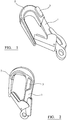
- the safety hook 1 has an upper section which has been retrofitted with a load detection sensor 5 formed by a layer of shrinkable polymer plastics material (such as polyolefin) incorporating, coated or impregnated with quantum tunnelling composite materials, such as QTC (RTM).
- This type of composite material is a mixture of conductive filler particles (such as highly-conductive metals) and elastomeric binders (for example silicone rubber) which use quantum tunnelling for pressure switching and sensing.
- Quantum tunnelling composite materials have the ability to change from an electrical insulator to a conductor when placed under pressure so that when pressure is absent the atoms of the conductive metals are too distant to conduct electricity but when pressure is applied, the conductive atoms congregate and electrons conduct electricity through the composite. Accordingly, these materials can be used to detect even very small changes due to compression, tension or other stresses.
- the load detection sensor 5 is able to detect a pressure change caused by a load being applied on the hook.
- the load detection sensor 5 described above can be shrunk onto a standard hook 1 such as a karabiner, ascender, descender, fall arrester, crane hook and scaffold hook by simply applying heat with a heat gun, or any method suitable to shrink-wrap the upper section of the hook.
- a transmitter 3 is connected to or included in the load detection sensor.
- the load detection sensor 5 perceives the pressure change generated by attaching the hook 1 to a rope or a lanyard and generates a first load status signal which is sent by the transmitter 3 to a receiver operably connected to processing means.
- the processing means analyses the load status signal and allows warning means to generate a notification or signal, for example a visible green light, to indicate that the hook is fastened.
- the load detection sensor 5 In the event the pressure changes again because a heavier load, such as one produced by a fall from a scaffold, is applied, the load detection sensor 5 generates a second load status signal.
- a second notification for example an audible alarm is generated by the warning means to enable the user and those around him to identify that a heavy load is being applied on the hook.
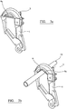
- a safety hook 1 comprising a load detection sensor 7 according to a second embodiment of the present invention.
- the load detection sensor is a piezoelectric sensor arranged to generate an electrical signal or electrical charge in response to pressure change.
- the load detection sensor 7 is mounted on a rigid plate which has been adhered to a standard safety hook 1.
- a transmitter 3 is also mounted on the plate.
- the safety system of this embodiment works in the same way as that described in relation to the safety system of the first embodiment.
- the load detection sensor 9 comprises a first and second self-energising switches mounted on a rigid plate which rigid plate is adhered to a standard safety hook 1, each self-energising switch being operably connected to a steel cable 9a.
- a transmitter 3 arranged to relay a load status signal is also mounted on the rigid plate.
- the first self-energising switch is arranged to be activated when the steel cable 9a is pulled so that when the safety hook 1 is connected to a line 10, the first switch is activated and generates a load detection signal which is relayed by the transmitter 3 to processing means.
- the second self-energising switch is arranged to be activated when the steel cable 9a is in a relaxed condition so that when the steel cable 9a is relaxed, the second self-energising switch is activated and a second load detection signal is relayed by the transmitter to the processing means.
- Figure 4 shows a processing unit or beacon 4 including processing means 2, the beacon 4 having an activation switch or other activation means 14, and an opening 13 for receiving a metallic ring 17 which allows the beacon to be secured to a standard harness.
- Warning means 12 in this instance a super bright LED, is secured to an end of the beacon 4.
- zip ties 16 are provided for securing the beacon 4 to items, such as clothing, which do not have a suitable opening 13.
- processing means 2 is operably connected to a receiver which receives a load status signal from a transmitter 3.
- a beacon 4 according to this embodiment of the present invention can be used with any of the load detection sensors 5, 7, 9 described in relation to Figures 1, 2 , 3a and 3b .
- the beacon 4 is powered with standard batteries, such as AA batteries.
- the beacon 4 comprises an activation switch 14 and a counter arranged to allow a user to activate the beacon 4 from a non-operational state to an operational state by pressing the activation switch 14.
- the counter measures a predetermined time interval, for example 3 months, and sends a time lapse signal to the processing means 2 once the predetermined time interval has elapsed.
- the processing means 2 are further arranged to analyse the time lapse signal and to produce a time output signal which time output signal causes the warning means to generate a time elapsed alarm, either visible, audible or both, to notify a user that the life-span of batteries has elapsed.
- the processing means monitors the batteries and also produces a time output signal if it detects that there is insufficient power left, i.e.
- a three month time interval is particularly useful because safety equipment is generally inspected every three months and, in general, batteries would be expected to have a useful life of around 3 months.
- the counter can be adapted to reset once the batteries have been replaced and the activation switch 14 has been pressed.
- the processing means 2 are housed in a processing unit comprising a super bright LED 12 and a metallic back plate 20 for securing the processing unit to a standard harness 6.
- the processing unit is powered by batteries and may include a counter.
- Display means 18 are secured to the processing unit to enable an equipment inspector to mark the processing unit with an inspection message including for example, date, time, and initials or name of the last check.
- FIG. 6 there is shown a scheme of a further embodiment of the present invention in which the processing means 2 are arranged to communicate wirelessly with a monitoring device 30, such as an on-site computer, to allow a supervisor 31, for example a site manager, to remotely monitor use of the safety equipment.
- a monitoring device 30 such as an on-site computer
- a supervisor 31 for example a site manager
- FIG. 6 there is shown a scheme of a further embodiment of the present invention in which the processing means 2 are arranged to communicate wirelessly with a monitoring device 30, such as an on-site computer, to allow a supervisor 31, for example a site manager, to remotely monitor use of the safety equipment.
- a monitoring device 30 such as an on-site computer
- Worker P2 is not hooked up and a warning signal is sent remotely to the monitoring device 30.
- the processing means 2 preferably includes a radio link to enable the supervisor to speak directly to the worker to check where the worker is and whether he/she should be hooked up or not, even though the employee may not be visible to the supervisor.
- Worker P4 is illustrated as having fallen which generates an emergency signal which is sent directly to the supervisor who can immediately identify the worker and implement SOS procedures. Thus, if there is an accident on-site, the supervisor is immediately and remotely alerted to facilitate a prompt and appropriate response.
- the processing means need not be housed in a processing unit and could be housed in the safety hook 1, for example.
- the warning means may be remotely connected to the processing means.
- the main purpose of the second hook is to enable workers to move position and to clip on the second hook in a new position, before removing the first hook. In this way the worker is always clipped in position.
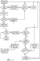
- FIG. 7 shows block diagram illustration the logic steps followed by processing means 2 according to the present invention.
- the system is provided with a day counter.
- the system establishes whether the counter has measured over 90 day (i.e. 3 months) of service. If the answer is yes, the processing unit causes the system to generate, for example, a flashing light and a sound to enable a user to remove the batteries from the processing unit to reset the system and, as a result, the counter is reset to zero. If the answer to the first step is no, the processing unit determines whether the battery level is under 5 %. If the battery level is below 5 %, the processing means cause the system to generate a constant light and a sound to alert a user that the battery is low.
- the processing means proceeds to the next step in which the processing means determines if the system is being used. If the system in in sleep mode, the processing unit follows repeats the step in a loop until it detects motion. On the other hand, if motion is detected, the processing means proceeds to the following step in which it checks whether a signal from the hook or hooks has been received. If no signals are detected, the processing means loops back to the first step in a loop and follows each subsequent step. If a positive signal from the hook or hooks is detected, the processing unit proceeds to determine whether the signal relates to a fall status.
- the processing means causes the system to generate flashing lights and a loud audible alarm to alert on-site personnel that a user is in danger.
- the system could be set up to prevent a reset when a fall signal has been detected. mode.
- the processing unit proceeds to determine whether the signal is constant or intermittent. If the signal has an interval of over 5 seconds, the processing means assumes that the hook or hooks are faulty or that the battery level is under 5 % and causes the system to generate a constant light and a sound. If the interval between two instances of detection of a signal is below 5 seconds, the processing means causes the system to produce a flashing light and a sound to alert on-site personnel that the user might be in danger.
- FIG. 8 there is shown block diagram illustration the logic steps followed by a pair of load detection sensors 5, 7, 9 connected to the processing means described in relation to Figures 4, 5 , 6 and 7 above. Each sensor follows the same logic steps simultaneously.
- the processing unit determines whether the battery level is over 5 %. If the battery level is under 5 %, the processing unit does not receive a signal from the hook. If the battery level is over 5 %, the processing means proceeds to determine whether the hook sensor detects a load over 0 N. If no load is detected, the processing means causes the system to generate a signal to alert the system that the user is not hooked. If a load is detected, the processing means determine whether the load is under 5 N.
- the processing means causes the system to generate a signal to indicate that the user is hooked. If the load detected is not under 5 N, the processing means determines whether the load exceeds 5 N. If the load detected does not exceed 5 N, the logic loops back to the first step. However, if the load detected by the hook sensor exceeds 5 N, the processing means causes the system to generate a FALL signal to alert on-site personnel that the user has suffered a fall. As the system shown in this figure comprises a pair of hooks, the processing means may be set up to generate an visual or audible alarm when either hook sensor detects a fall (i.e. a load which exceeds 5 N). In addition, the processing means may be programmed to generate an alarm when it detects that neither hook is connected to a line.
- a transmitter 3 suitable for use with any of the embodiments of the present invention comprises a 433 MHz PCB antenna.
- One of the main advantages of the present system, and in particular of the embodiment described in relation to Figure 6 is that a supervisor can monitor whether any given user is employing safety equipment appropriately at any given time so that on-site personnel are encouraged to adhere to safety regulations and to use safety equipment. Moreover, it would allow evaluating personnel safety equipment history so that individual users found to systematically disregard safety regulations can be disciplined. Further, it would also allow a supervisor to monitor safety equipment use remotely so that regardless of the size of the site or project, a supervisor would always know if personnel are connected to a line and if an accident has occurred.
- one of the greatest advantages of the present invention is that it can be used with standard equipment such as harnesses, lanyards, hooks, ties and rope without altering the structural integrity of the standard equipment. Further, retrofitting the existing standard equipment is straightforward; as a result, there is not need to invest heavily in new equipment, so implementation costs are nominal.
- the embodiments above have been described in relation to a single safety hook, it should be clear to the skilled person that the safety system of the present invention could also be used with a two or more hooks so that the warning means generate a signal to indicate that all the two or more hooks are disconnected, connected or that a load greater than a predetermined value is being applied to one of the two or more hooks.
- the invention can be used with different types of hooks such as karabiners, ascenders, descenders, fall arresters, crane hooks and scaffold hooks.
- the notifications generated by the warning means may be lights of different colours, lights flashing in different patterns, audible alarms, a combination of coloured/flashing lights and an audible alarm or any other suitable means to attract attention.
- processing and warning means according to the invention have been described as being separate from the load detection sensor, it would possible to integrate both of these into a safety hook comprising a load detection sensor according to the present invention, for example by mounting them in the rigid plate described in relation to the second and third embodiments or by adhering them to the layer of shrinkable polymer plastics material described in relation to the first embodiment once heat has been applied to it.
- beacon and control unit could be powered with any suitable power source other than batteries, such as: a kinetic power generator/microgenerator or a solar power cell.
- safety system of the present invention has been described in relation to its use in the construction industry, it should be clear to the skilled person that the safety system could also be used for scaffolding, climbing, abseiling, sailing, rope rescue, industrial rope work, window cleaning and any other activity in which safety belts and or harnesses are necessary.
Applications Claiming Priority (2)
| Application Number | Priority Date | Filing Date | Title |
|---|---|---|---|
| GB1219688.7A GB2510096B (en) | 2012-11-01 | 2012-11-01 | Safety equipment |
| EP13811589.4A EP2914350B1 (en) | 2012-11-01 | 2013-10-30 | Safety equipment |
Related Parent Applications (2)
| Application Number | Title | Priority Date | Filing Date |
|---|---|---|---|
| EP13811589.4A Division EP2914350B1 (en) | 2012-11-01 | 2013-10-30 | Safety equipment |
| EP13811589.4A Division-Into EP2914350B1 (en) | 2012-11-01 | 2013-10-30 | Safety equipment |
Publications (2)
| Publication Number | Publication Date |
|---|---|
| EP3138610A1 EP3138610A1 (en) | 2017-03-08 |
| EP3138610B1 true EP3138610B1 (en) | 2018-02-28 |
Family
ID=47359020
Family Applications (2)
| Application Number | Title | Priority Date | Filing Date |
|---|---|---|---|
| EP13811589.4A Active EP2914350B1 (en) | 2012-11-01 | 2013-10-30 | Safety equipment |
| EP16193804.8A Active EP3138610B1 (en) | 2012-11-01 | 2013-10-30 | Safety equipment |
Family Applications Before (1)
| Application Number | Title | Priority Date | Filing Date |
|---|---|---|---|
| EP13811589.4A Active EP2914350B1 (en) | 2012-11-01 | 2013-10-30 | Safety equipment |
Country Status (14)
| Country | Link |
|---|---|
| US (2) | US20150265860A1 (es) |
| EP (2) | EP2914350B1 (es) |
| JP (1) | JP6369838B2 (es) |
| KR (1) | KR102186674B1 (es) |
| CN (2) | CN105025987B (es) |
| AU (1) | AU2013340560B2 (es) |
| CA (1) | CA2890005C (es) |
| DK (2) | DK3138610T3 (es) |
| ES (2) | ES2620024T3 (es) |
| GB (1) | GB2510096B (es) |
| HK (1) | HK1217118A1 (es) |
| NO (1) | NO3138610T3 (es) |
| NZ (1) | NZ708471A (es) |
| WO (1) | WO2014068266A2 (es) |
Families Citing this family (40)
| Publication number | Priority date | Publication date | Assignee | Title |
|---|---|---|---|---|
| GB2510096B (en) * | 2012-11-01 | 2015-08-26 | Skanska Uk Plc | Safety equipment |
| US10138102B2 (en) * | 2013-07-23 | 2018-11-27 | Viki V. Walbridge | Warning and message delivery and logging system utilizable in a fall arresting and prevention device and method of same |
| US9519853B2 (en) * | 2013-11-01 | 2016-12-13 | James P Tolle | Wearable, non-visible identification device for friendly force identification and intruder detection |
| GB2530121B (en) * | 2014-08-05 | 2016-11-23 | Cord Safe Ltd | Motor safety device with an alarm element |
| JP2016038665A (ja) * | 2014-08-06 | 2016-03-22 | 株式会社大林組 | 作業用スーツ |
| US9480866B2 (en) * | 2014-10-21 | 2016-11-01 | The Boeing Company | Line connector having a link detection system and method of making same |
| US10769925B2 (en) * | 2015-12-30 | 2020-09-08 | 3M Innovative Properties Company | Electronic fall event communication system |
| KR101804040B1 (ko) | 2016-03-07 | 2017-12-04 | 서규선 | 이중 락이 구비된 산업용 안전 훅 |
| CN105725299A (zh) * | 2016-04-01 | 2016-07-06 | 德清申力索具有限公司 | 一种安全衣 |
| US10843016B2 (en) | 2016-04-14 | 2020-11-24 | Honeywell International Inc. | Weight bearing fall protection connector having a wireless fall indicator |
| US10617985B2 (en) * | 2016-09-29 | 2020-04-14 | Rosemount Inc. | Gas sensor module with field replaceable, ingress protected, sensor filter |
| JP6665766B2 (ja) * | 2016-12-09 | 2020-03-13 | トヨタ自動車株式会社 | 歩行訓練装置 |
| US20200016439A1 (en) * | 2017-03-31 | 2020-01-16 | 3M Innovative Properties Company | Fall protection equipment connection status and control |
| US11298572B2 (en) * | 2017-07-18 | 2022-04-12 | Smart Harness Systems, LLC | Safety system with digital tracking and reporting and method of use |
| CN114613102A (zh) * | 2017-10-27 | 2022-06-10 | 霍尼韦尔国际公司 | 智能高度安全系统 |
| CN108525153A (zh) * | 2018-05-04 | 2018-09-14 | 乐清市盛邦安防有限公司 | 一种智能挂钩以及智能挂钩的控制系统 |
| KR101964727B1 (ko) * | 2018-08-22 | 2019-04-02 | 주식회사 지에스아이엘 | 고소작업용 안전벨트 유니트를 이용한 작업 안전 관리시스템 |
| US20210016116A1 (en) * | 2018-09-25 | 2021-01-21 | Jimi Ip, Llc | Safety Check Apparatus for Challenge Course |
| KR101932022B1 (ko) * | 2018-11-21 | 2018-12-27 | (주)창조인 | 교육용 완강기 |
| JP2022527448A (ja) | 2019-03-22 | 2022-06-02 | スリーエム イノベイティブ プロパティズ カンパニー | 監視システムを有する落下防止システム |
| CA3145804A1 (en) * | 2019-07-10 | 2021-01-14 | 3M Innovative Properties Company | Fall-protection apparatus with multimodal inductive sensing |
| KR102399579B1 (ko) * | 2019-08-20 | 2022-05-18 | 주식회사 티앤블루랩 | 고소작업용 안전벨트 유닛 |
| US20210060366A1 (en) * | 2019-08-28 | 2021-03-04 | Oshkosh Corporation | Fall arrest system |
| CN110559570A (zh) * | 2019-09-02 | 2019-12-13 | 成都建工第五建筑工程有限公司 | 感应装置、检测系统及安全挂钩 |
| CN110404272B (zh) * | 2019-09-09 | 2023-09-01 | 中国计量大学 | 用于滑索规范安全操作的装置 |
| US11247080B2 (en) * | 2019-10-10 | 2022-02-15 | Saudi Arabian Oil Company | Systems, methods, and apparatuses for ensuring worker safety |
| KR102377955B1 (ko) * | 2019-12-13 | 2022-03-23 | 임홍규 | 스마트 안전고리 |
| GB2591083A (en) * | 2020-01-02 | 2021-07-21 | Cape Industrial Services Ltd | Safety harness system |
| JP7462288B2 (ja) | 2020-01-10 | 2024-04-05 | 株式会社谷沢製作所 | フック使用監視装置 |
| KR20210101767A (ko) | 2020-02-11 | 2021-08-19 | 동서대학교 산학협력단 | 안전고리장치 |
| CN111458129A (zh) * | 2020-04-29 | 2020-07-28 | 江苏省特种设备安全监督检验研究院 | 一种高精度起重机悬臂梁在线检测系统 |
| US11623108B2 (en) | 2020-05-19 | 2023-04-11 | Us Safety Technologies Llc | Safety harness motion detector systems and methods for use |
| US11065481B1 (en) * | 2020-05-19 | 2021-07-20 | Us Safety Technologies Llc | Safety harness motion detector systems and methods for use |
| US11663897B2 (en) * | 2020-07-16 | 2023-05-30 | Joseph Clinton Meyers | Apparatus for anchoring a fall protection system and transmitting a fall alert |
| EP4319886A1 (en) * | 2021-04-09 | 2024-02-14 | Bosch Sanayi Ve Ticaret Anonim Sirketi | Monitoring device for a fall protection system for persons and fall protection system for persons |
| CN113463936B (zh) * | 2021-05-28 | 2022-11-15 | 锡林郭勒热电有限责任公司 | 自动跟随的防坠保护装置和安全监控系统 |
| WO2023020685A1 (en) * | 2021-08-17 | 2023-02-23 | Nrg Tech Ltd. | Safety carabiner |
| CN114288581A (zh) * | 2022-01-05 | 2022-04-08 | 郑鸿 | 一种安全挂钩、安全绳及安全实现方法 |
| CO2022006531A1 (es) * | 2022-05-17 | 2023-02-06 | Morcillo Munoz Freddy | Mecanismo de sujeción para trabajo en altura con resistencia mejorada y detección ante el riesgo eléctrico |
| CN115212483B (zh) * | 2022-07-20 | 2023-05-16 | 广东电网有限责任公司 | 一种高空作业安全带状态监控系统与方法 |
Family Cites Families (41)
| Publication number | Priority date | Publication date | Assignee | Title |
|---|---|---|---|---|
| US2647293A (en) * | 1947-10-06 | 1953-08-04 | Andrew F Wintercorn | Fire safety appliance for application to the outside of windows |
| GB1360234A (en) * | 1971-04-16 | 1974-07-17 | Lucas Industries Ltd | Safety arrangements for road vehicles |
| JPS5236976U (es) * | 1975-09-08 | 1977-03-16 | ||
| US4423796A (en) * | 1982-11-23 | 1984-01-03 | Sulowski Andrew C | Ladder climber's safety device |
| JPH0411050U (es) * | 1990-05-16 | 1992-01-29 | ||
| JP2602143B2 (ja) * | 1992-02-20 | 1997-04-23 | 株式会社マコム | 通電式ワイヤ張力検出型警戒センサ |
| JP2834619B2 (ja) * | 1992-07-24 | 1998-12-09 | 矢崎総業株式会社 | ガス漏れ警報装置 |
| JPH0694561A (ja) * | 1992-09-11 | 1994-04-05 | Matsushita Electric Ind Co Ltd | 圧電型圧力センサ |
| US5998402A (en) * | 1996-04-19 | 1999-12-07 | American Home Products Corporation | 2-phenyl-1-[4-(2-aminoethoxy)-benzyl]-indoles as estrogenic agents |
| FR2755236B3 (fr) * | 1996-10-24 | 1998-12-24 | Henri Joachim Victor Brunet | Capteur d'effort avec alarme radio pour la protection de personnes ou de dispositifs industriels |
| US6619549B2 (en) * | 2001-09-21 | 2003-09-16 | Metrologic Instruments, Inc. | Bar code symbol reading device having intelligent data communication interface to a host system |
| WO2000019052A1 (en) * | 1998-09-30 | 2000-04-06 | Baillargeon Paul D | Fall protection system and method |
| JP3390421B2 (ja) * | 2001-02-20 | 2003-03-24 | 株式会社弥生機工 | 高所作業用安全ベルト装置 |
| US7106205B2 (en) * | 2004-09-16 | 2006-09-12 | D B Industries, Inc. | Alarm device for use with fall protection equipment |
| DE102005035556A1 (de) * | 2005-07-29 | 2007-02-01 | Clyde Bergemann Gmbh | Selektive Reinigung von Wärmeaustauscheinrichtungen im Kessel einer Verbrennungsanlage |
| JP2007044166A (ja) * | 2005-08-08 | 2007-02-22 | Chugoku Electric Power Co Inc:The | 取付確認センサ |
| AT504458B1 (de) * | 2006-10-23 | 2010-02-15 | Strasser Philipp Mag | Selbstsicherungsset sowie anlage mit sicherungsstellen |
| US7913569B2 (en) * | 2007-12-11 | 2011-03-29 | Israel Aerospace Industries Ltd. | Magnetostrictive type strain sensing means and methods |
| AT506420B1 (de) * | 2008-02-06 | 2011-07-15 | Strasser Philipp Mag | Sicherungseinrichtung |
| US8141681B2 (en) * | 2008-04-07 | 2012-03-27 | Safeworks, Llc | Tower climbing assist device |
| JP5147636B2 (ja) * | 2008-10-17 | 2013-02-20 | 藤井電工株式会社 | 安全帯および安全帯の装着確認システム |
| US8325053B2 (en) * | 2009-03-10 | 2012-12-04 | JCJ Inc. | Personal fall protection monitoring system |
| JP5359661B2 (ja) * | 2009-08-03 | 2013-12-04 | 日本電気株式会社 | 安全管理システム、安全管理装置、安全管理方法、及びプログラム |
| JP5116815B2 (ja) * | 2009-10-20 | 2013-01-09 | 藤井電工株式会社 | 安全帯およびその使用状況確認システム |
| US8675823B2 (en) * | 2009-10-30 | 2014-03-18 | Hooten Investments, Inc. | Method and apparatus for activating a communication device operably connected to a safety lanyard |
| JP5805974B2 (ja) * | 2010-03-31 | 2015-11-10 | ティーケー ホールディングス,インコーポレーテッド | ステアリングホイールセンサ |
| US8902074B2 (en) * | 2010-08-26 | 2014-12-02 | Honeywell International, Inc. | Harness for fall protection |
| FR2967076B1 (fr) * | 2010-11-08 | 2012-11-30 | Thierry Jean Alain Cornil Dehondt | Dispositif d'arrimage de securite et ensemble d'arrimage pourvu d'un tel dispositif |
| GB2486012A (en) * | 2010-12-01 | 2012-06-06 | Dessa Ltd | Alarm for fall arrest system |
| US9245434B2 (en) * | 2011-02-09 | 2016-01-26 | Paul D. Baillargeon | Warning and message delivery and logging system utilizable in the monitoring of fall arresting and prevention devices and method of same |
| GB2491376B (en) * | 2011-06-01 | 2014-01-08 | Fall Safe Assist Ltd | Hip impact protector |
| JP5335054B2 (ja) * | 2011-11-09 | 2013-11-06 | ホーチキ株式会社 | 警報器 |
| CN102512773B (zh) * | 2012-02-02 | 2013-10-23 | 中国十七冶集团有限公司 | 一种用于安全绳佩戴状态远程监测装置 |
| GB2510096B (en) * | 2012-11-01 | 2015-08-26 | Skanska Uk Plc | Safety equipment |
| US9153115B1 (en) * | 2013-03-28 | 2015-10-06 | Eric Ulner | Fall impact signal transmitter |
| US10138102B2 (en) * | 2013-07-23 | 2018-11-27 | Viki V. Walbridge | Warning and message delivery and logging system utilizable in a fall arresting and prevention device and method of same |
| US9861839B2 (en) * | 2014-02-19 | 2018-01-09 | D B Industries, Llc | Connector |
| US9623270B2 (en) * | 2014-06-25 | 2017-04-18 | Fall-Botics, Llc | Personal safety apparatus and system |
| JP6906757B2 (ja) * | 2017-06-28 | 2021-07-21 | 株式会社テック技販 | 安全帯使用状況確認システム |
| JP2020043964A (ja) * | 2018-09-18 | 2020-03-26 | 株式会社プロップ | 安全帯用発報装置 |
| US11029224B2 (en) * | 2019-06-04 | 2021-06-08 | Lockheed Martin Corporation | Method for thermally correcting data obtained through strain gauges mounted to a surface |
-
2012
- 2012-11-01 GB GB1219688.7A patent/GB2510096B/en active Active
-
2013
- 2013-10-30 NZ NZ708471A patent/NZ708471A/en unknown
- 2013-10-30 JP JP2015540200A patent/JP6369838B2/ja active Active
- 2013-10-30 AU AU2013340560A patent/AU2013340560B2/en active Active
- 2013-10-30 ES ES13811589.4T patent/ES2620024T3/es active Active
- 2013-10-30 DK DK16193804.8T patent/DK3138610T3/en active
- 2013-10-30 CA CA2890005A patent/CA2890005C/en active Active
- 2013-10-30 ES ES16193804.8T patent/ES2665333T3/es active Active
- 2013-10-30 EP EP13811589.4A patent/EP2914350B1/en active Active
- 2013-10-30 CN CN201380057687.6A patent/CN105025987B/zh active Active
- 2013-10-30 US US14/439,611 patent/US20150265860A1/en not_active Abandoned
- 2013-10-30 NO NO16193804A patent/NO3138610T3/no unknown
- 2013-10-30 WO PCT/GB2013/000462 patent/WO2014068266A2/en active Application Filing
- 2013-10-30 CN CN201811207926.2A patent/CN109589516A/zh active Pending
- 2013-10-30 DK DK13811589.4T patent/DK2914350T3/en active
- 2013-10-30 KR KR1020157014371A patent/KR102186674B1/ko active IP Right Grant
- 2013-10-30 EP EP16193804.8A patent/EP3138610B1/en active Active
-
2016
- 2016-05-04 HK HK16105097.3A patent/HK1217118A1/zh unknown
-
2019
- 2019-05-20 US US16/417,067 patent/US11969612B2/en active Active
Non-Patent Citations (1)
| Title |
|---|
| None * |
Also Published As
| Publication number | Publication date |
|---|---|
| CA2890005C (en) | 2021-09-07 |
| JP6369838B2 (ja) | 2018-08-08 |
| WO2014068266A2 (en) | 2014-05-08 |
| GB201219688D0 (en) | 2012-12-12 |
| DK3138610T3 (en) | 2018-06-14 |
| ES2665333T3 (es) | 2018-04-25 |
| CA2890005A1 (en) | 2014-05-08 |
| EP3138610A1 (en) | 2017-03-08 |
| EP2914350A2 (en) | 2015-09-09 |
| KR102186674B1 (ko) | 2020-12-07 |
| KR20150084023A (ko) | 2015-07-21 |
| GB2510096B (en) | 2015-08-26 |
| CN109589516A (zh) | 2019-04-09 |
| AU2013340560B2 (en) | 2017-12-07 |
| DK2914350T3 (en) | 2017-03-27 |
| US11969612B2 (en) | 2024-04-30 |
| GB2510096A (en) | 2014-07-30 |
| US20190269949A1 (en) | 2019-09-05 |
| NZ708471A (en) | 2017-12-22 |
| US20150265860A1 (en) | 2015-09-24 |
| EP2914350B1 (en) | 2016-12-14 |
| HK1217118A1 (zh) | 2016-12-23 |
| CN105025987A (zh) | 2015-11-04 |
| JP2015533440A (ja) | 2015-11-24 |
| NO3138610T3 (es) | 2018-07-28 |
| WO2014068266A3 (en) | 2014-08-28 |
| CN105025987B (zh) | 2018-11-13 |
| AU2013340560A1 (en) | 2015-06-04 |
| ES2620024T3 (es) | 2017-06-27 |
Similar Documents
| Publication | Publication Date | Title |
|---|---|---|
| US11969612B2 (en) | Safety equipment | |
| CN106492368B (zh) | 一种基于gprs通讯技术的电厂高空作业智能安全带 | |
| KR101526938B1 (ko) | 현장 안전관리용 실시간 경보시스템 및 그 구동방법 | |
| KR101964727B1 (ko) | 고소작업용 안전벨트 유니트를 이용한 작업 안전 관리시스템 | |
| US20200242915A1 (en) | Fall detection alert/alarm device and method | |
| US11730984B2 (en) | Weight bearing fall protection connector having a wireless fall indicator | |
| CN210655725U (zh) | 一种电梯监控报警装置 | |
| CN207867646U (zh) | 一种安检设备防入侵监测装置及安检设备 | |
| KR102286381B1 (ko) | 고소작업용 안전고리 체결 확인 센서를 구비한 안전관리 시스템 | |
| CN209173258U (zh) | 带报警装置的安全带 | |
| KR20230125957A (ko) | 산업용안전조끼하네스알람 | |
| TWM654308U (zh) | 防墜落與感電之提醒裝置 |
Legal Events
| Date | Code | Title | Description |
|---|---|---|---|
| PUAI | Public reference made under article 153(3) epc to a published international application that has entered the european phase |
Free format text: ORIGINAL CODE: 0009012 |
|
| 17P | Request for examination filed |
Effective date: 20161013 |
|
| AC | Divisional application: reference to earlier application |
Ref document number: 2914350 Country of ref document: EP Kind code of ref document: P |
|
| AK | Designated contracting states |
Kind code of ref document: A1 Designated state(s): AL AT BE BG CH CY CZ DE DK EE ES FI FR GB GR HR HU IE IS IT LI LT LU LV MC MK MT NL NO PL PT RO RS SE SI SK SM TR |
|
| GRAP | Despatch of communication of intention to grant a patent |
Free format text: ORIGINAL CODE: EPIDOSNIGR1 |
|
| INTG | Intention to grant announced |
Effective date: 20170921 |
|
| GRAS | Grant fee paid |
Free format text: ORIGINAL CODE: EPIDOSNIGR3 |
|
| GRAA | (expected) grant |
Free format text: ORIGINAL CODE: 0009210 |
|
| AC | Divisional application: reference to earlier application |
Ref document number: 2914350 Country of ref document: EP Kind code of ref document: P |
|
| AK | Designated contracting states |
Kind code of ref document: B1 Designated state(s): AL AT BE BG CH CY CZ DE DK EE ES FI FR GB GR HR HU IE IS IT LI LT LU LV MC MK MT NL NO PL PT RO RS SE SI SK SM TR |
|
| REG | Reference to a national code |
Ref country code: GB Ref legal event code: FG4D Ref country code: CH Ref legal event code: EP |
|
| REG | Reference to a national code |
Ref country code: AT Ref legal event code: REF Ref document number: 973493 Country of ref document: AT Kind code of ref document: T Effective date: 20180315 |
|
| REG | Reference to a national code |
Ref country code: IE Ref legal event code: FG4D |
|
| REG | Reference to a national code |
Ref country code: DE Ref legal event code: R096 Ref document number: 602013033919 Country of ref document: DE |
|
| REG | Reference to a national code |
Ref country code: ES Ref legal event code: FG2A Ref document number: 2665333 Country of ref document: ES Kind code of ref document: T3 Effective date: 20180425 |
|
| REG | Reference to a national code |
Ref country code: SE Ref legal event code: TRGR |
|
| REG | Reference to a national code |
Ref country code: DK Ref legal event code: T3 Effective date: 20180606 |
|
| REG | Reference to a national code |
Ref country code: NL Ref legal event code: MP Effective date: 20180228 |
|
| REG | Reference to a national code |
Ref country code: LT Ref legal event code: MG4D |
|
| REG | Reference to a national code |
Ref country code: AT Ref legal event code: MK05 Ref document number: 973493 Country of ref document: AT Kind code of ref document: T Effective date: 20180228 |
|
| PG25 | Lapsed in a contracting state [announced via postgrant information from national office to epo] |
Ref country code: FI Free format text: LAPSE BECAUSE OF FAILURE TO SUBMIT A TRANSLATION OF THE DESCRIPTION OR TO PAY THE FEE WITHIN THE PRESCRIBED TIME-LIMIT Effective date: 20180228 Ref country code: HR Free format text: LAPSE BECAUSE OF FAILURE TO SUBMIT A TRANSLATION OF THE DESCRIPTION OR TO PAY THE FEE WITHIN THE PRESCRIBED TIME-LIMIT Effective date: 20180228 Ref country code: NL Free format text: LAPSE BECAUSE OF FAILURE TO SUBMIT A TRANSLATION OF THE DESCRIPTION OR TO PAY THE FEE WITHIN THE PRESCRIBED TIME-LIMIT Effective date: 20180228 Ref country code: LT Free format text: LAPSE BECAUSE OF FAILURE TO SUBMIT A TRANSLATION OF THE DESCRIPTION OR TO PAY THE FEE WITHIN THE PRESCRIBED TIME-LIMIT Effective date: 20180228 Ref country code: CY Free format text: LAPSE BECAUSE OF FAILURE TO SUBMIT A TRANSLATION OF THE DESCRIPTION OR TO PAY THE FEE WITHIN THE PRESCRIBED TIME-LIMIT Effective date: 20180228 |
|
| REG | Reference to a national code |
Ref country code: NO Ref legal event code: T2 Effective date: 20180228 |
|
| PG25 | Lapsed in a contracting state [announced via postgrant information from national office to epo] |
Ref country code: BG Free format text: LAPSE BECAUSE OF FAILURE TO SUBMIT A TRANSLATION OF THE DESCRIPTION OR TO PAY THE FEE WITHIN THE PRESCRIBED TIME-LIMIT Effective date: 20180528 Ref country code: GR Free format text: LAPSE BECAUSE OF FAILURE TO SUBMIT A TRANSLATION OF THE DESCRIPTION OR TO PAY THE FEE WITHIN THE PRESCRIBED TIME-LIMIT Effective date: 20180529 Ref country code: LV Free format text: LAPSE BECAUSE OF FAILURE TO SUBMIT A TRANSLATION OF THE DESCRIPTION OR TO PAY THE FEE WITHIN THE PRESCRIBED TIME-LIMIT Effective date: 20180228 Ref country code: RS Free format text: LAPSE BECAUSE OF FAILURE TO SUBMIT A TRANSLATION OF THE DESCRIPTION OR TO PAY THE FEE WITHIN THE PRESCRIBED TIME-LIMIT Effective date: 20180228 Ref country code: AT Free format text: LAPSE BECAUSE OF FAILURE TO SUBMIT A TRANSLATION OF THE DESCRIPTION OR TO PAY THE FEE WITHIN THE PRESCRIBED TIME-LIMIT Effective date: 20180228 |
|
| REG | Reference to a national code |
Ref country code: FR Ref legal event code: PLFP Year of fee payment: 6 |
|
| PG25 | Lapsed in a contracting state [announced via postgrant information from national office to epo] |
Ref country code: PL Free format text: LAPSE BECAUSE OF FAILURE TO SUBMIT A TRANSLATION OF THE DESCRIPTION OR TO PAY THE FEE WITHIN THE PRESCRIBED TIME-LIMIT Effective date: 20180228 Ref country code: EE Free format text: LAPSE BECAUSE OF FAILURE TO SUBMIT A TRANSLATION OF THE DESCRIPTION OR TO PAY THE FEE WITHIN THE PRESCRIBED TIME-LIMIT Effective date: 20180228 Ref country code: IT Free format text: LAPSE BECAUSE OF FAILURE TO SUBMIT A TRANSLATION OF THE DESCRIPTION OR TO PAY THE FEE WITHIN THE PRESCRIBED TIME-LIMIT Effective date: 20180228 Ref country code: AL Free format text: LAPSE BECAUSE OF FAILURE TO SUBMIT A TRANSLATION OF THE DESCRIPTION OR TO PAY THE FEE WITHIN THE PRESCRIBED TIME-LIMIT Effective date: 20180228 Ref country code: RO Free format text: LAPSE BECAUSE OF FAILURE TO SUBMIT A TRANSLATION OF THE DESCRIPTION OR TO PAY THE FEE WITHIN THE PRESCRIBED TIME-LIMIT Effective date: 20180228 |
|
| REG | Reference to a national code |
Ref country code: DE Ref legal event code: R097 Ref document number: 602013033919 Country of ref document: DE |
|
| PG25 | Lapsed in a contracting state [announced via postgrant information from national office to epo] |
Ref country code: SM Free format text: LAPSE BECAUSE OF FAILURE TO SUBMIT A TRANSLATION OF THE DESCRIPTION OR TO PAY THE FEE WITHIN THE PRESCRIBED TIME-LIMIT Effective date: 20180228 Ref country code: SK Free format text: LAPSE BECAUSE OF FAILURE TO SUBMIT A TRANSLATION OF THE DESCRIPTION OR TO PAY THE FEE WITHIN THE PRESCRIBED TIME-LIMIT Effective date: 20180228 Ref country code: CZ Free format text: LAPSE BECAUSE OF FAILURE TO SUBMIT A TRANSLATION OF THE DESCRIPTION OR TO PAY THE FEE WITHIN THE PRESCRIBED TIME-LIMIT Effective date: 20180228 |
|
| PLBE | No opposition filed within time limit |
Free format text: ORIGINAL CODE: 0009261 |
|
| STAA | Information on the status of an ep patent application or granted ep patent |
Free format text: STATUS: NO OPPOSITION FILED WITHIN TIME LIMIT |
|
| 26N | No opposition filed |
Effective date: 20181129 |
|
| PG25 | Lapsed in a contracting state [announced via postgrant information from national office to epo] |
Ref country code: SI Free format text: LAPSE BECAUSE OF FAILURE TO SUBMIT A TRANSLATION OF THE DESCRIPTION OR TO PAY THE FEE WITHIN THE PRESCRIBED TIME-LIMIT Effective date: 20180228 |
|
| REG | Reference to a national code |
Ref country code: CH Ref legal event code: PL |
|
| GBPC | Gb: european patent ceased through non-payment of renewal fee |
Effective date: 20181030 |
|
| REG | Reference to a national code |
Ref country code: BE Ref legal event code: MM Effective date: 20181031 |
|
| PG25 | Lapsed in a contracting state [announced via postgrant information from national office to epo] |
Ref country code: LU Free format text: LAPSE BECAUSE OF NON-PAYMENT OF DUE FEES Effective date: 20181030 Ref country code: MC Free format text: LAPSE BECAUSE OF FAILURE TO SUBMIT A TRANSLATION OF THE DESCRIPTION OR TO PAY THE FEE WITHIN THE PRESCRIBED TIME-LIMIT Effective date: 20180228 |
|
| REG | Reference to a national code |
Ref country code: IE Ref legal event code: MM4A |
|
| PG25 | Lapsed in a contracting state [announced via postgrant information from national office to epo] |
Ref country code: LI Free format text: LAPSE BECAUSE OF NON-PAYMENT OF DUE FEES Effective date: 20181031 Ref country code: CH Free format text: LAPSE BECAUSE OF NON-PAYMENT OF DUE FEES Effective date: 20181031 Ref country code: BE Free format text: LAPSE BECAUSE OF NON-PAYMENT OF DUE FEES Effective date: 20181031 |
|
| PG25 | Lapsed in a contracting state [announced via postgrant information from national office to epo] |
Ref country code: IE Free format text: LAPSE BECAUSE OF NON-PAYMENT OF DUE FEES Effective date: 20181030 Ref country code: GB Free format text: LAPSE BECAUSE OF NON-PAYMENT OF DUE FEES Effective date: 20181030 |
|
| PG25 | Lapsed in a contracting state [announced via postgrant information from national office to epo] |
Ref country code: MT Free format text: LAPSE BECAUSE OF NON-PAYMENT OF DUE FEES Effective date: 20181030 |
|
| PG25 | Lapsed in a contracting state [announced via postgrant information from national office to epo] |
Ref country code: TR Free format text: LAPSE BECAUSE OF FAILURE TO SUBMIT A TRANSLATION OF THE DESCRIPTION OR TO PAY THE FEE WITHIN THE PRESCRIBED TIME-LIMIT Effective date: 20180228 |
|
| PG25 | Lapsed in a contracting state [announced via postgrant information from national office to epo] |
Ref country code: PT Free format text: LAPSE BECAUSE OF FAILURE TO SUBMIT A TRANSLATION OF THE DESCRIPTION OR TO PAY THE FEE WITHIN THE PRESCRIBED TIME-LIMIT Effective date: 20180228 |
|
| PG25 | Lapsed in a contracting state [announced via postgrant information from national office to epo] |
Ref country code: MK Free format text: LAPSE BECAUSE OF NON-PAYMENT OF DUE FEES Effective date: 20180228 Ref country code: HU Free format text: LAPSE BECAUSE OF FAILURE TO SUBMIT A TRANSLATION OF THE DESCRIPTION OR TO PAY THE FEE WITHIN THE PRESCRIBED TIME-LIMIT; INVALID AB INITIO Effective date: 20131030 |
|
| PG25 | Lapsed in a contracting state [announced via postgrant information from national office to epo] |
Ref country code: IS Free format text: LAPSE BECAUSE OF FAILURE TO SUBMIT A TRANSLATION OF THE DESCRIPTION OR TO PAY THE FEE WITHIN THE PRESCRIBED TIME-LIMIT Effective date: 20180628 |
|
| REG | Reference to a national code |
Ref country code: DE Ref legal event code: R082 Ref document number: 602013033919 Country of ref document: DE Representative=s name: JENSENS IP LIMITED, IE |
|
| PGFP | Annual fee paid to national office [announced via postgrant information from national office to epo] |
Ref country code: ES Payment date: 20231121 Year of fee payment: 11 |
|
| PGFP | Annual fee paid to national office [announced via postgrant information from national office to epo] |
Ref country code: SE Payment date: 20231030 Year of fee payment: 11 Ref country code: NO Payment date: 20231010 Year of fee payment: 11 Ref country code: FR Payment date: 20231026 Year of fee payment: 11 Ref country code: DK Payment date: 20231027 Year of fee payment: 11 Ref country code: DE Payment date: 20231011 Year of fee payment: 11 |