EP3137795B1 - Vorrichtung zur steuerung oder regelung der durchflussmenge und/oder durchflussrichtung von fluiden - Google Patents
Vorrichtung zur steuerung oder regelung der durchflussmenge und/oder durchflussrichtung von fluiden Download PDFInfo
- Publication number
- EP3137795B1 EP3137795B1 EP15717108.3A EP15717108A EP3137795B1 EP 3137795 B1 EP3137795 B1 EP 3137795B1 EP 15717108 A EP15717108 A EP 15717108A EP 3137795 B1 EP3137795 B1 EP 3137795B1
- Authority
- EP
- European Patent Office
- Prior art keywords
- arm
- housing
- closure element
- closure
- outlet
- Prior art date
- Legal status (The legal status is an assumption and is not a legal conclusion. Google has not performed a legal analysis and makes no representation as to the accuracy of the status listed.)
- Active
Links
- 239000012530 fluid Substances 0.000 title claims description 24
- 230000001276 controlling effect Effects 0.000 title description 2
- 230000001105 regulatory effect Effects 0.000 title description 2
- 238000007789 sealing Methods 0.000 claims description 45
- 230000001954 sterilising effect Effects 0.000 claims description 6
- 238000006073 displacement reaction Methods 0.000 claims description 2
- 230000008901 benefit Effects 0.000 description 18
- 230000007935 neutral effect Effects 0.000 description 10
- 235000013305 food Nutrition 0.000 description 8
- 239000002184 metal Substances 0.000 description 7
- 238000003860 storage Methods 0.000 description 6
- 229910001220 stainless steel Inorganic materials 0.000 description 5
- 239000010935 stainless steel Substances 0.000 description 5
- 238000004659 sterilization and disinfection Methods 0.000 description 5
- 238000004519 manufacturing process Methods 0.000 description 4
- 238000004806 packaging method and process Methods 0.000 description 4
- 241000309551 Arthraxon hispidus Species 0.000 description 2
- IJGRMHOSHXDMSA-UHFFFAOYSA-N Atomic nitrogen Chemical compound N#N IJGRMHOSHXDMSA-UHFFFAOYSA-N 0.000 description 2
- MHAJPDPJQMAIIY-UHFFFAOYSA-N Hydrogen peroxide Chemical compound OO MHAJPDPJQMAIIY-UHFFFAOYSA-N 0.000 description 2
- 239000004696 Poly ether ether ketone Substances 0.000 description 2
- 238000004140 cleaning Methods 0.000 description 2
- 238000005520 cutting process Methods 0.000 description 2
- 238000011010 flushing procedure Methods 0.000 description 2
- 239000007789 gas Substances 0.000 description 2
- 229920002530 polyetherether ketone Polymers 0.000 description 2
- 230000036316 preload Effects 0.000 description 2
- 238000005096 rolling process Methods 0.000 description 2
- 239000007787 solid Substances 0.000 description 2
- 239000003206 sterilizing agent Substances 0.000 description 2
- 239000002253 acid Substances 0.000 description 1
- 230000009471 action Effects 0.000 description 1
- 239000003513 alkali Substances 0.000 description 1
- JUPQTSLXMOCDHR-UHFFFAOYSA-N benzene-1,4-diol;bis(4-fluorophenyl)methanone Chemical compound OC1=CC=C(O)C=C1.C1=CC(F)=CC=C1C(=O)C1=CC=C(F)C=C1 JUPQTSLXMOCDHR-UHFFFAOYSA-N 0.000 description 1
- 230000005540 biological transmission Effects 0.000 description 1
- BVKZGUZCCUSVTD-UHFFFAOYSA-N carbonic acid Chemical compound OC(O)=O BVKZGUZCCUSVTD-UHFFFAOYSA-N 0.000 description 1
- 230000008859 change Effects 0.000 description 1
- 239000012459 cleaning agent Substances 0.000 description 1
- 238000002485 combustion reaction Methods 0.000 description 1
- 230000008878 coupling Effects 0.000 description 1
- 238000010168 coupling process Methods 0.000 description 1
- 238000005859 coupling reaction Methods 0.000 description 1
- 238000001514 detection method Methods 0.000 description 1
- 230000003670 easy-to-clean Effects 0.000 description 1
- 239000004519 grease Substances 0.000 description 1
- 239000007788 liquid Substances 0.000 description 1
- 239000000314 lubricant Substances 0.000 description 1
- 238000012423 maintenance Methods 0.000 description 1
- 239000000463 material Substances 0.000 description 1
- 229910052757 nitrogen Inorganic materials 0.000 description 1
- 239000004033 plastic Substances 0.000 description 1
- 229920003023 plastic Polymers 0.000 description 1
- 230000004044 response Effects 0.000 description 1
- XLYOFNOQVPJJNP-UHFFFAOYSA-N water Chemical compound O XLYOFNOQVPJJNP-UHFFFAOYSA-N 0.000 description 1
- 238000003466 welding Methods 0.000 description 1
Images


Classifications
-
- F—MECHANICAL ENGINEERING; LIGHTING; HEATING; WEAPONS; BLASTING
- F16—ENGINEERING ELEMENTS AND UNITS; GENERAL MEASURES FOR PRODUCING AND MAINTAINING EFFECTIVE FUNCTIONING OF MACHINES OR INSTALLATIONS; THERMAL INSULATION IN GENERAL
- F16K—VALVES; TAPS; COCKS; ACTUATING-FLOATS; DEVICES FOR VENTING OR AERATING
- F16K11/00—Multiple-way valves, e.g. mixing valves; Pipe fittings incorporating such valves
- F16K11/10—Multiple-way valves, e.g. mixing valves; Pipe fittings incorporating such valves with two or more closure members not moving as a unit
- F16K11/14—Multiple-way valves, e.g. mixing valves; Pipe fittings incorporating such valves with two or more closure members not moving as a unit operated by one actuating member, e.g. a handle
- F16K11/18—Multiple-way valves, e.g. mixing valves; Pipe fittings incorporating such valves with two or more closure members not moving as a unit operated by one actuating member, e.g. a handle with separate operating movements for separate closure members
-
- F—MECHANICAL ENGINEERING; LIGHTING; HEATING; WEAPONS; BLASTING
- F16—ENGINEERING ELEMENTS AND UNITS; GENERAL MEASURES FOR PRODUCING AND MAINTAINING EFFECTIVE FUNCTIONING OF MACHINES OR INSTALLATIONS; THERMAL INSULATION IN GENERAL
- F16K—VALVES; TAPS; COCKS; ACTUATING-FLOATS; DEVICES FOR VENTING OR AERATING
- F16K1/00—Lift valves or globe valves, i.e. cut-off apparatus with closure members having at least a component of their opening and closing motion perpendicular to the closing faces
- F16K1/16—Lift valves or globe valves, i.e. cut-off apparatus with closure members having at least a component of their opening and closing motion perpendicular to the closing faces with pivoted closure-members
- F16K1/18—Lift valves or globe valves, i.e. cut-off apparatus with closure members having at least a component of their opening and closing motion perpendicular to the closing faces with pivoted closure-members with pivoted discs or flaps
- F16K1/20—Lift valves or globe valves, i.e. cut-off apparatus with closure members having at least a component of their opening and closing motion perpendicular to the closing faces with pivoted closure-members with pivoted discs or flaps with axis of rotation arranged externally of valve member
- F16K1/2021—Lift valves or globe valves, i.e. cut-off apparatus with closure members having at least a component of their opening and closing motion perpendicular to the closing faces with pivoted closure-members with pivoted discs or flaps with axis of rotation arranged externally of valve member with a plurality of valve members
-
- F—MECHANICAL ENGINEERING; LIGHTING; HEATING; WEAPONS; BLASTING
- F16—ENGINEERING ELEMENTS AND UNITS; GENERAL MEASURES FOR PRODUCING AND MAINTAINING EFFECTIVE FUNCTIONING OF MACHINES OR INSTALLATIONS; THERMAL INSULATION IN GENERAL
- F16K—VALVES; TAPS; COCKS; ACTUATING-FLOATS; DEVICES FOR VENTING OR AERATING
- F16K11/00—Multiple-way valves, e.g. mixing valves; Pipe fittings incorporating such valves
- F16K11/02—Multiple-way valves, e.g. mixing valves; Pipe fittings incorporating such valves with all movable sealing faces moving as one unit
- F16K11/04—Multiple-way valves, e.g. mixing valves; Pipe fittings incorporating such valves with all movable sealing faces moving as one unit comprising only lift valves
- F16K11/052—Multiple-way valves, e.g. mixing valves; Pipe fittings incorporating such valves with all movable sealing faces moving as one unit comprising only lift valves with pivoted closure members, e.g. butterfly valves
Definitions
- the invention relates to a device for controlling or regulating the flow rate and / or flow direction of fluids, comprising: a housing with at least two inlets and / or outlets, at least one arm which is arranged to be movable within the housing, and at least one closure element which is arranged inside of the housing is arranged and movably connected to the arm, and a prestressed spring element which is arranged between the arm and the closure element, the arm and the closure element connected to it being arranged and connected to one another such that at least one inlet and / or outlet can be shut off, and wherein the closure element and / or at least one inlet and / or outlet has a curved sealing surface for sealing the inlets and / or outlets.
- the invention also relates to the use of such a device in the sterilization of food packaging and / or its contents.
- Flowing fluids - i.e. gases or liquids - can be influenced in different ways.
- the aim of this influencing can be, for example, to control or regulate the flow rate or the flow direction of the fluids.
- numerous devices are known from the prior art, which are often referred to as valves.
- a group of the valves are directional valves or multi-way valves, which are characterized in that they have three or more fluid connections and are switchable.
- an inlet can be connected to a first outlet or to a second outlet as required, and the flow can thus be directed in different directions.
- both outlets can be closed so that the flow is completely interrupted.
- the Flow rate intermediate positions are also taken, in which the outlets are only partially open.
- a particular challenge with valves has traditionally been to be able to shut off the outlets particularly reliably in order to completely prevent the fluid flow.
- These components can be, for example, a closure element that can be pressed onto a valve seat and can be lifted off the valve seat again.
- sealing surfaces made of rubber are known which are provided on the closure element or the valve seat.
- the rubber can compensate for unevenness on the contact surfaces, so that a particularly good seal is achieved.
- rubber sealing surfaces cannot be used in many applications. For example, rubber sealing surfaces can be damaged at very high pressures or very high temperatures.
- sealing surfaces made of rubber do not meet the strict hygienic requirements that are placed on the systems used, for example, when filling food.
- valves with metallic sealing surfaces are preferred, particularly in the case of high hygienic requirements, since they are particularly easy to clean and have a higher resistance to cleaning agents, sterilizing agents and the foods to be filled.
- a challenge with closure elements with metallic sealing surfaces is to achieve a secure seal. Because of the very high rigidity and the associated very low elasticity, metallic sealing surfaces can hardly adapt to the surfaces of the valve seats assigned to them, and inevitably existing manufacturing tolerances or alignment errors compensate only to a very limited extent. In addition to manufacturing tolerances, minor deformations within the valve must also be compensated for, which arise, for example, due to very high mechanical or thermal loads. In order to counter these problems, it has already been proposed to use valves in which the closure elements have metallic sealing surfaces, but the closure elements are pivotably mounted within the valve.
- a device according to the preamble features of claim 1 is from DE-A-10 2010 018 674 known.
- JP 7-224633 A known (also in Fig. 6 the US 5,908,047 shown as prior art). It is a valve for the exhaust system of an internal combustion engine.
- the valve includes a housing with one inlet and two outlets.
- a pivoted arm In the housing there is a pivoted arm, at the end of which two fastening elements with spherical sealing surfaces are attached.
- the first closure element closes the first outlet or the second closure element closes the second outlet.
- the fastening elements are fastened to the arm via a swivel joint, so that the fastening elements can be pivoted by a small angle with respect to the arm.
- a disadvantage of that from the JP 7-224633 A known valve is that the pivot joint that connects the closure elements to the arm has only one degree of freedom of movement; the swivel joint therefore only allows the locking elements to be pivoted about a fixed axis of rotation.
- the teaching of the JP 7-224633 A can be countered by the fact that the arm is connected to the housing by means of a rotating push joint and can therefore not only be pivoted but also moved in height.
- the closure elements can still only be pivoted about an axis; on the other hand, there is no provision for pivoting about a second axis perpendicular to the first axis, so that there is no possibility of being able to compensate for so-called “angular errors”.
- the swivel joint does not allow a linear one Movement, i.e. no change in distance between the closure elements and the arm.
- the proposed solution has the disadvantage that the joints used (rotating joint, rotating sliding joint) do not allow the locking elements to be specifically oriented. In particular, when the arm is pivoted, there is a risk that the closure elements will be brought into an undesired position under the influence of the weight and / or the fluid flow, which complicates the subsequent placement of the closure elements on other outlets to be sealed.
- the invention is based on the object of designing and developing the above-mentioned device in such a way that a high degree of mobility of the closure element in the loaded state is achieved with a simultaneously defined orientation of the closure element in the unloaded state and with improved sealing at the same time.
- the device according to the invention is initially characterized by a housing which has at least two inlets and / or outlets.
- a fluid can flow into the housing through the inlets, and can flow out of the housing again through the outlets.
- Inlets and outlets can also be generally referred to as "connections", so that it is a housing with at least two connections.
- a device with two connections - for example an inlet and an outlet - can be used as a simple shut-off valve.
- a device with at least three connections - for example an inlet and two outlets - can, however, be used as a switchable multi-way valve. For this reason, devices are preferred which have at least three inlets and / or outlets.
- the housing is preferably made of metal, in particular stainless steel.
- At least one arm which is movable within of the housing is arranged and in particular can be movably connected to the housing.
- the arm can be connected to the housing directly or indirectly, that is to say via further components.
- the arm is also preferably made of metal, in particular stainless steel.
- at least one closure element is provided, which is arranged within the housing and is movably connected to the arm.
- the connection between the closure element and the arm can also be made directly or indirectly, for example via a joint.
- Metal, in particular stainless steel is also preferably used to produce the closure element. It is provided that the arm and the closure element connected to it are arranged and connected to one another such that at least one inlet and / or outlet can be shut off by the closure element.
- closure element and / or at least one inlet and / or outlet - in particular the inlet or outlet to be shut off by this closure element - provide a curved sealing surface Seals the inlets and / or outlets.
- prestressed spring elements Another advantage of the prestressed spring elements is that - with appropriate storage of the closure element - the function of a safety valve or pressure relief valve can be guaranteed. This is because when a permissible response pressure in the inlet or outlet to be sealed is exceeded, the spring elements allow the closure element to be opened easily, as a result of which fluid is discharged from the inlet or outlet to be sealed and the pressure prevailing there is reduced. In this way, the systems connected to the device can be protected against an impermissible increase in pressure and associated damage. As soon as the pressure drops below a certain level again, the spring element presses the closure element again firmly onto the inlet or outlet to be sealed and seals it.
- the spring element is preferably only clamped or clamped between the arm and the closure element (non-positive connection) without being welded to one of these components.
- This has the advantage that the spring element can slide on the arm and / or on the closure element.
- the spring element can be welded to one of the two adjacent components (integral connection) and slide on the other of the two adjacent components. Due to an annular design of the spring element, the spring element can be guided around a narrow point of the closure element, for example, so that captive storage is ensured even without welding (positive connection).
- the arm has at least one through hole through which two closure elements, which are arranged on opposite sides of the arm, are connected to one another.
- a particularly simple and reliable connection can be created between the closure element and the arm: two oppositely arranged closure elements are connected to one another through the through hole provided in the arm, thereby simultaneously connecting the both locking elements are reached with the arm.
- a detachable connection is preferred for maintenance reasons; the two opposing closure elements can be screwed together, for example.
- an internal thread can be provided in both closure elements, so that both closure elements can be held together by a grub screw with an external thread.
- the setscrew is screwed into one of the two closure elements and the spring element is attached.
- This locking element can then be inserted with the grub screw first through the through hole of the arm.
- a spring element can also be plugged on and the second closure element screwed onto the threaded pin, so that both closure elements are firmly connected to one another.
- the through hole can have a circular cross section or have another suitable shape (for example "elongated hole”, “cloverleaf", "oval").
- the through hole have a diameter that is larger than the minimum diameter that the two closure elements connected to one another have.
- both closure elements have their smallest diameter at the point that is assigned to the other closure element.
- the smallest diameter of the two closure elements is preferably of the same size, so that when the two closure elements are joined together, the minimum diameter arises in the region of the contact surfaces of the two closure elements. Because the minimum diameter is smaller than the diameter of the through hole, there is no interference fit, but a clearance fit. The consequence of this is that the two interconnected closure elements are mounted so that they can move relative to the arm.
- the closure elements can carry out both a linear movement and a pivoting movement relative to the arm, so that particularly flexible mobility is achieved.
- the previously described prestressed spring element nevertheless ensures that the two closure elements do not slide back and forth in the through hole in an uncontrolled manner in the relieved state, but instead assume a defined starting position.
- the minimum diameter of the closure elements can range between 5 mm and 40 mm; the diameter of the through hole can be in the range between 6 mm and 45 mm. If the through hole does not have a circular cross section, the diameter of the through hole denotes the minimum width of its opening at the point at which the closure elements are guided through the through hole.
- the through hole has a diameter that is smaller than the maximum diameter that the two interconnected closure elements have.
- the maximum diameter of the closure elements can range between 30 mm and 300 mm. If the through hole does not have a circular cross section, the diameter of the through hole denotes the minimum width of its opening at the point at which the closure elements are guided through the through hole.
- the closure element is movably connected to the arm via a ball joint.
- a ball joint achieves mobility of the closure element with three degrees of freedom, namely a rotation about the axis of symmetry and a pivoting movement about two axes perpendicular to the axis of rotation.
- Storage by means of a ball joint has the advantage over the previously described solution that there is no need for a second, oppositely arranged closure element for storage. This is because the joint head can be provided on the closure element and the joint socket can be provided on the arm (or vice versa). Flushing grooves can be provided on the joint head and / or on the joint socket through which a cleaning or sterilizing medium can be passed.
- a ball joint can also be ideally supplemented by the spring element described above, so that the closure element is always returned to a defined starting position by the spring element in the released state.
- the lack of a possibility of linear movement of ball joints can be compensated for, for example, by appropriate arm positioning.
- a further teaching of the invention proposes that the arm can be pivoted about an axis of rotation which has a fixed position relative to the housing.
- An axis of rotation with a fixed position has the advantage that in the housing - and possibly the housing cover - fixed bearing points can be provided for the axis of rotation. Compared to an axis of rotation with a variable position, this is much easier to manufacture and also has hygienic advantages.
- a fixed axis of rotation with a corresponding arrangement of the axis of rotation and the inlets or outlets in the housing, can achieve that a plurality of different inlets or outlets can be reached and thus be closed by the closure elements of this arm by the closure elements of one arm. If there are several arms, it can be provided that each arm can be pivoted about an axis of rotation which has a fixed position relative to the housing.
- the closure element and / or at least one inlet and / or outlet has a convexly curved sealing surface.
- a convex, that is to say curved outward, sealing surface ensures that the sealing surfaces can reach the surfaces assigned to them on the valve seats particularly reliably.
- line contact with the circumferential edges on the valve seats can be achieved by convex sealing surfaces even if chamfers are present on these edges. This enables a reliable sealing of the inlets or outlets.
- each closure element has a convexly curved sealing surface. The same advantages result if the convexly curved sealing surface is not present on the closure element, but rather on the inlet or outlet to be sealed.
- the closure element and / or at least one inlet and / or outlet has a spherical sealing surface.
- the sealing surfaces do not necessarily have to be completely spherical or even have the shape of a solid ball; instead, it is sufficient if the sealing surfaces are spherical in the area that can come into contact with the valve seats.
- a spherical sealing surface has the advantage that the closure elements are also in one achieve an optimal seal because the cross-sectional area of a ball - and thus also the shape of the contact line between the closure element and the valve seat - never changes, but is always circular.
- each closure element has a spherical sealing surface.
- the spherically curved sealing surface is not present on the closure element, but rather on the inlet or outlet to be sealed.
- a further embodiment of the invention provides that the inlets and / or outlets are circular in shape at their end arranged in the housing. Because of their symmetry, circular ends of the inlets or outlets have the advantage that appropriately shaped closure elements can also reliably seal the inlets or outlets in a position rotated relative to the starting position.
- the use of inlets or outlets with a circular end is particularly advantageous for closure elements with spherical sealing surfaces. Because any cutting plane of a sphere is circular, so that a closure element with spherical sealing surfaces can achieve a reliable seal of an inlet or outlet with a circular end not only in a rotated position but even in a pivoted position. Circular inlets or outlets can be created very easily by cutting pipes with a cylindrical cross section straight - that is, at right angles to their longitudinal axis.
- the arm comprises at least two parts which are movably connected to one another, the first part being pivotable about an axis of rotation which has a fixed position relative to the housing, and the second part and each further part at least one axis of rotation is pivotable, which has a fixed position relative to the adjacent part.
- the arms can be attached to the arms by means of multi-part or multi-unit arms Closure elements are moved particularly variably, so that with such arms with an equal number of closure elements compared to one-piece arms, an increased number of switching positions can often be achieved.
- the different parts of the arm are preferably connected to one another by joints, in particular by swivel joints. If there are several arms, it can be provided that each arm is designed in several parts in the manner described above.
- At least one closure element is movably connected to the first part of the arm and / or that at least one closure element is movably connected to the second part and / or each further part of the arm.
- the fact that the closure elements can be attached to any part of the arm further increases the variability of the movement and thus the number of switch positions that can be carried out.
- the arm can be used in a particularly variable manner if fastening elements are fastened not only to one but to several parts of the arm.
- Two or more closure elements can also be attached to the same part of the arm, the opposite arrangement of two closure elements described above being preferred due to the possibility of attachment by means of a through hole. If there are several arms, it can be provided that each arm is designed in the manner described above.
- a further embodiment of the invention is characterized by an actuator for moving the arm, the actuator being arranged outside the housing.
- An actuator in some cases also called an actuator, can be used to easily achieve a movement, in particular a rotary movement, of the arm. Pneumatic as well as hydraulic or electrical actuators can be used for this.
- the arrangement outside the housing has the advantage that the actuator can be easily replaced and that the actuator does not influence the fluid flowing through the housing or - for example, contaminated by oil or grease. If there are several arms, each arm can be provided by an actuator is moved. In this case, each arm can be assigned its own actuator, or several arms can be moved by the same actuator, for example using suitable mechanics.
- the actuator is mechanically connected to the arm.
- a mechanical connection has the advantage of a particularly reliable and precise power transmission.
- the connection can be realized, for example, by providing a sealed bushing for the arm or the actuator or a connecting element in the housing.
- the actuator be coupled to the arm without contact, in particular magnetically.
- a contactless connection in particular a “magnetic coupling” means that mechanical components can be dispensed through the housing, thus ensuring a good seal even at high pressures and difficult-to-seal fluids (e.g. gases).
- each of the bearings can be arranged particularly close to the inlet or outlet to be sealed - that is, outside - and can therefore guide the arm particularly precisely.
- the possibility of a linear movement of the arms also enables a particularly uniform control of the flow rate, since the gap which forms between the closure element and the inlet or outlet to be sealed is the same size at every point.
- the arms are preferably in the radial direction slidable relative to the common linear guide or to the separate linear guides.
- the radial displaceability can be achieved, for example, by providing radial bores in the linear guides, in which the arms are movably guided.
- the bores can include rinsing grooves running in the longitudinal direction, through which fluids can be passed for sterilization.
- This design of the device can be supplemented by at least one adjusting disk rotatably connected to the housing and having at least one outward or inward contour for the radial displacement of the arms.
- the linear movement of the arms can be coupled to the rotational movement of the adjusting plate by means of a rotatably mounted adjusting plate.
- This can be implemented, for example, in that a wheel is attached to each arm that, when the adjusting disk rotates, rolls or slides on its contour and thereby presses the arm and the closure element attached to it in the radial direction against a spring pressure inwards or outwards or can come out or in again in the radial direction due to the spring pressure.
- the contour of the adjusting disk is preferably shaped in such a way that its course changes its radial distance from the axis of rotation of the adjusting disk.
- the arms can also be moved by the fluid flowing through the device or another fluid.
- Detection points can be provided on the contour of the adjusting disk, which represent a defined position for the wheels.
- the contour of the adjusting disc can be shaped such that when the adjusting disc rotates, all the arms to be moved by the adjusting disc move synchronously. In the case of a symmetrical arrangement of the inlets or outlets to be sealed, this is the case, for example, when the contour of the adjusting disk is also symmetrically shaped. As an alternative to this, the contour of the adjusting disc can be shaped in such a way that when the adjusting disc rotates, the arms to be moved do not move synchronously. Such a design can be achieved, for example, by first opening a first inlet around the housing flushing a first fluid before opening a second inlet to flow a second fluid through the housing.
- the adjusting disks are preferably mounted in the housing in the direction of their axis of rotation and have differently shaped contours. This has the advantage that it is possible to "switch" between the different adjusting disks in order to achieve different movements of the arms and thus different switching positions.
- the adjusting disks can be arranged like sprockets in a sprocket assembly or sprocket assembly of a bicycle.
- Another advantage of multiple setting disks is that some (or all) of the adjusting disks can only be assigned to a few arms. This can be achieved, for example, in that the wheels of the arms rolling or sliding on the contours of the adjusting disks are arranged in different planes which correspond to the levels of the adjusting disks acting on them.
- some (or all) of the adjusting disks are not fully circulating, but can only be rotated through a limited angular range, and thus can only address arms arranged within this angular range.
- This has the advantage that several adjusting disks, for example shaped like a circular sector, can be arranged next to one another without colliding.
- adjusting disks When using several adjusting disks, it can further be provided that some (or all) of the adjusting disks are driven by separate drives. This has the advantage that the adjusting disks - and the arms they move - can be addressed individually, which enables particularly variable control of the flow rates and flow directions.
- a common drive can be provided for all adjusting disks, which is particularly simple to construct.
- a particularly advantageous use of the device described above in all the configurations described lies in the sterilization of food packaging.
- the suitability of the device for this purpose is firstly that a secure sealing of the inlets or outlets is made possible and that several switching positions are possible, as a result of which it is possible to switch between several fluids used in the sterilization of food packaging (e.g. sterile air, water vapor, hydrogen peroxide , Acid, alkali, cleaning medium, condensate, nitrogen, carbonic acid or food to be filled).
- several fluids used in the sterilization of food packaging e.g. sterile air, water vapor, hydrogen peroxide , Acid, alkali, cleaning medium, condensate, nitrogen, carbonic acid or food to be filled.
- a particular suitability results from the fact that those closure elements which do not seal any inlet or outlet in the set switch position are inevitably flowed around by the fluid used for the sterilization of the food packaging due to their constant arrangement within the housing, so that these closure elements and in particular their spring elements are also necessarily cleaned and sterilized.
- the suitability for the stated purpose also results from the fact that all parts of the device can be made from materials that meet the highest hygienic requirements (eg stainless steel) and that the device can be operated without lubricants.
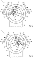
- Fig. 1a and Fig. 1b show a first embodiment of a device 1 according to the invention in a first and in a second switching position in plan view.
- the device 1 shown comprises a cylindrical housing 2 which has an inlet 3 and two outlets 4a, 4b.
- the inlet 3 and the two outlets 4a, 4b are short cylindrical metal tubes, each of which has a flange 5a, 5b at their ends outside the housing 2, on which (in Fig. 1a / Fig. 1b pipes or hoses (not shown) can be connected.
- the housing 2 also has a flange 6 on which a (in Fig. 1a / Fig. 1b not shown) housing cover can be placed and screwed to the housing 2.
- the inlet 3 was connected to the housing 2 in such a way that the end of the inlet 3 adapts to the cylindrical shape of the housing 2. Accordingly, the inlet 3 does not protrude into the housing 2.
- the inlets 4a, 4b project into the housing 2 with their ends 7a, 7b.
- the cylindrical inlets 4a, 4b were cut straight at their ends 7a, 7b arranged in the housing 2 - that is to say at right angles to their longitudinal axis - so that the two outlets 4a, 4b are circular in shape at their ends 7a, 7b arranged in the housing ,
- an arm 8 is provided, which is arranged within the housing 2 and is movably connected to the housing 2.
- the movable mounting of the arm 8 takes place via an axis of rotation 9 about which the arm 8 can be pivoted.
- the axis of rotation 9 has a fixed position relative to the housing 2, it is rotatably mounted, for example, with its two ends in the bottom and in the cover of the housing 2.
- the arm 8 carries at its end two opposing locking elements 10a, 10b.
- Spring element 11a, 11b made of metal, which allows a relative movement between the two closure elements 10a, 10b and the arm 8 and which returns the two closure elements 10a, 10b to an initial position in the unloaded state.
- the spring elements 11a, 11b are preferably only clamped between the arm 8 and the two closure elements 10a, 10b.
- the legs of the spring elements 11a, 11b can therefore slide on the surface of the arm 8 and / or on the surfaces of the closure elements 10a, 10b.
- the left closure element 10a is assigned to the left outlet 4a and, with the arm 8 in a corresponding position, can close the left outlet 4a, so that the fluid flowing into the housing 2 through the inlet 3 exits the housing 2 through the right, open outlet 4b can.
- This position is in Fig. 1 shown (flow direction indicated by arrows).
- the right closure element 10b is assigned to the right outlet 4b and can, when the arm 8 is in a corresponding position, close the right outlet 4b, so that the fluid flowing into the housing 2 through the inlet 3 flows out of the housing 2 through the left, open outlet 4a can leak.
- Fig. 1b shown (flow direction indicated by arrows).
- the closure elements 10a, 10b have curved sealing surfaces 12a, 12b, which is in connection with 1c and 1d is discussed in more detail below.
- a closed position of the arm 8 is also possible in the closed positions shown, in which both outlets 4a, 4b are open.
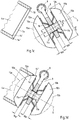
- Fig. 1c it can be seen on the left that the outlet 4a has a circumferential chamfer 13 in the region of its end 7a.
- the chamfer 13 creates two circumferential edges 14 ', 14 ", of which the inner edge 14' is used as a sealing edge.
- the outer edge 14" or another one between the two edges 14 ', 14 "arranged edge can be used as a sealing edge.
- both closure elements 10a, 10b are rotationally symmetrical and have an axis of symmetry S which is perpendicular to arm 8 in the starting position shown.
- the sealing surfaces 12a, 12b of the closure elements 10a, 10b are convexly curved outwards and each lie completely on a spherical surface 15a, 15b.
- the sealing surfaces 12a, 12b are therefore spherically curved.
- the two spherical surfaces 15a, 15b can be part of a common spherical surface or span two different spherical surfaces that are not congruent.
- the closure elements 10a, 10b do not form a solid ball, since on the one hand the ball dome is missing in the outer region and on the other hand the closure elements 10a, 10b are designed to be considerably slimmer in the inner region so that the arm 8 and the spring elements 11a, 11b can be arranged there.
- Fig. 1d the closed switch position is shown, in which the arm 8 is pivoted to the left, so that the closure element 10a is pressed onto the left outlet 4a in order to close it.
- the closure element 10a When pressed together, there is a circumferential line contact between the inner edge 14 'of the left outlet 4a and the sealing surface 12a of the closure element 10a.
- the other areas of the outlet 4a in particular the chamfer 13 with the outer edge 14 ′′, have no contact with the sealing surface 12a of the closure element 10a.
- the contact pressure is concentrated to a very low level Surface so that a very high pressure is created, which leads to a particularly reliable seal.
- the two opposite closure elements 10a, 10b are connected to one another, in particular screwed.
- an internal thread can be provided in both closure elements 10a, 10b, so that both closure elements 10a, 10b can be held together by a grub screw with an external thread.
- the connection between the two closure elements 10a, 10b and the arm 8 takes place, for example, via a through hole 16 which is provided in the arm 8.
- a set screw is screwed into one of the two closure elements 10a and the spring element 11a is attached. This closure element 10a is then inserted with the grub screw first through the through hole 16 of the arm 8.
- the spring element 11b can then be plugged on from the other side and the second closure element 10b can be screwed onto the threaded pin, so that both closure elements 10a, 10b are firmly connected to one another. It can be provided that the joint gap that arises between the two closure elements 10a, 10b is provided with a seal and / or is glued.
- the through hole 16 has a diameter D that is larger than the minimum diameter D min that the two interconnected closure elements 10a, 10b have.
- the minimum diameter D min is preferably in the region of the parting plane of the two closure elements 10a, 10b connected to one another. Since the minimum diameter D min is smaller than the diameter D of the through hole 16, the two closure elements 10a, 10b can be moved very freely and, in particular, both be displaced in the direction of the axis of symmetry S and inclined in each direction with respect to the axis of symmetry S.
- the diameter D of the through hole 16 is larger than the minimum diameter D min of the two interconnected closure elements 10a, 10b, it is smaller than the maximum diameter D max of the two interconnected closure elements 10a, 10b.
- the maximum diameter D max of the two interconnected closure elements 10a, 10b is larger than the diameter D of the through hole 16, it is achieved that the two interconnected closure elements 10a, 10b do not can slip out of the through hole 16 and are thus captively and yet movably connected to the arm 8.
- the prestressed spring elements 11a, 11b which are clamped on both sides between the arm 8 and the two interconnected closure elements 10a, 10b, prevent the closure elements 10a, 10b from loosely sliding back and forth in the through hole 16.
- the spring elements 11a, 11b thus achieve an alignment or leveling of the closure elements 10a, 10b in the unloaded state.
- the spring elements 11a, 11b are evenly biased, with a distance 16a between the rear of the closure element 10a and the arm 8.
- the distance 16a corresponds to the distance 16b.
- the bias of the spring elements 11a, 11b also ensures a precise, tilt-free alignment of the two closure elements 10a, 10b.
- the spring elements 11a, 11b also allow (in Fig. 1d (not shown) pivoting movement of the closure elements 10a, 10b relative to the arm 8.
- the pivoting movement means that the axis of symmetry S of the closure elements 10a, 10b is no longer perpendicular to the arm 8.
- the extent of the pivoting movement of the closure elements 10a, 10b can be in the range between ⁇ 0.1 ° and 20 ° (in both directions).
- each closure element 10a, 10b can also be connected to the arm 8 via a ball joint (not shown), wherein a prestressed spring element 11a, 11b should also be arranged between the closure element 10a, 10b and the arm 8, around which Align closure element 10a, 10b in the unloaded state.
- the device 1 described belongs to the group of directional valves, which are regularly classified according to the number of connections and the number of possible switching positions. Since the in 1a to 1d shown embodiment of the device 1 a total of 3 connections (one inlet 3 and two outlets 4a, 4b) are present and - apart from the neutral switching position - two switching positions are possible, it is a 3/2-way valve.
- Fig. 2a shows a second embodiment of a device 1 according to the invention in plan view.
- the already related to 1a to 1d Areas of the device 1 described are in Fig. 2a provided with corresponding reference numerals.
- the main difference from the first embodiment ( 1a to 1d ) is that in the second embodiment of the device 1 according to the invention two further outlets 4a ', 4b' are provided, so that a total of four outlets 4a, 4a ', 4b, 4b' are present.
- each outlet 4a, 4a ', 4b, 4b' there is in turn a flange 5a, 5a ', 5b, 5b' for connecting hoses or pipes and an end 7a, 7a ', 7b, 7b' projecting into the housing 2.
- the illustrated embodiment of the device 1 also has an elongated arm 8, on which a total of four closure elements 10a, 10a ', 10b, 10b' on the previously described manner - that is, through a passage of the closure elements 10a, 10a ', 10b, 10b' through a through hole 16 of the arm 8 with simultaneous alignment by prestressed spring elements 11a, 11b.
- the arrangement of the closure elements 10a, 10a ', 10b, 10b' on the arm 8 and the arrangement of the outlets 4a, 4a ', 4b, 4b' are coordinated with one another such that at a pivoting of the arm 8 to the left, the outlets 4a and 4a 'are closed by the closure elements 10a and 10a'.
- the housing 2 in this embodiment of the device 1 has an angular shape, two outlets being arranged side by side in the same side surface of the housing 2.
- a neutral position of the arm 8 is also possible, in which all four outlets 4a, 4a ', 4b, 4b' are open. Since the in Fig. 2a shown embodiment of the device 1 a total of 5 connections (an inlet 3 and four outlets 4a, 4a ', 4b, 4b') are present and - apart from the neutral switching position - two switching positions are possible, it is a 5/2-way valve ,
- Fig. 2b is the device 1 off Fig. 2a shown with a modified arm 8.
- the arm 8 comprises two parts 8a, 8b which are movably connected to one another by a joint 17.
- the first part 8a of the arm 8 is pivotable about the axis of rotation 9 and the second part 8b of the arm 8 is pivotable about the first part 8a of the arm 8 due to the joint 17.
- This has the consequence that the first part 8a of the arm 8 is pivotable about an axis of rotation which has a fixed position relative to the housing 2, while the second part 8b of the arm 8 is pivotable about an axis of rotation running through the joint 17, which is relative to the first part 8a of the arm 8 has a fixed position. Due to the modified arm 8 in Fig.
- 2b Device 1 shown assume four switching positions: With a collinear alignment of the two parts 8a, 8b of the arm 8, there are two switching positions which correspond to the switching positions which were previously in connection with Fig. 2a have been described; when the two parts 8a, 8b of the arm 8 are bent however, there are two new switch positions.
- the closure element 10b can block the outlet 4b while the second part 8b of the arm 8 is pivoted back, so that the closure element 10b 'attached to it leaves the outlet 4b' open ( Fig. 2b ).
- Fig. 2b In corresponding (in Fig.
- the closure element 10a can block the outlet 4a while the second part 8b of the arm 8 is pivoted back, so that the closure element 10a 'attached to it leaves the outlet 4a' open.
- the second part 8b of the arm 8 can, for example, be pressed into the bent position by a leg spring arranged in or on the arm 8 (in Fig. 2b not shown).
- the straight, collinear alignment of the two parts 8a, 8b of the arm 8 can be achieved by aligning the two parts 8a, 8b of the arm 8 while overcoming the spring force by means of a cable (“Bowden cable”) arranged in or on the arm 8 (in Fig. 2b not shown).
- the two parts 8a, 8b of the arm 8 can also be straightened by compressed air or (electro) magnetic forces. Since the in Fig. 2b shown embodiment of the device 1 a total of 5 connections (an inlet 3 and four outlets 4a, 4a ', 4b, 4b') are available and - apart from the neutral switching position - four switching positions are possible, it is a 5/4-way valve ,
- Fig. 3 shows a third embodiment of a device 1 according to the invention in plan view.
- the already related to 1a to 2b Areas of the device 1 described are in Fig. 3 provided with corresponding reference numerals.
- the main difference from the first embodiment ( 1a to 1d ) and the second embodiment ( Fig. 2a and Fig. 2b ) is that in the third embodiment of the device 1 according to the invention, two separate arms 8, 8 'are provided, each of which can be pivoted about an axis of rotation 9, 9'.
- the two axes of rotation 9, 9 ' lie on opposite sides of the housing 2 and have a fixed position relative to the housing 2.
- the second embodiment Fig. 2a and Fig.
- outlets 4a, 4a ', 4b, 4b' there are also a total of four outlets 4a, 4a ', 4b, 4b' in the third embodiment of the device 1 according to the invention.
- outlets 4a, 4a ', 4b, 4b' there is a flange 5a, 5a ', 5b, 5b' for connecting Hoses or tubes and an end 7a, 7a ', 7b, 7b' projecting into the housing 2 are provided.
- the length of the arm 8 and the position of its axis of rotation 9, the arrangement of the closure elements 10a, 10b on the arm 8 and the arrangement of the outlets 4a, 4b are coordinated with one another such that when the arm 8 is pivoted, either the outlet 4a through the closure element 10a is closed or that the outlet 4b is closed by the closure element 10b.
- neutral positions of the arms 8, 8 ' are also possible, in which all outlets 4a, 4a', 4b, 4b 'remain open.
- the housing 2 in this embodiment of the device 1 has an elongated shape which comprises two opposite straight side faces and two opposite curved side faces, the two arms 8, 8' each in the area a curved side surface of the housing 2 are arranged.
- the connection between the closure elements 10a, 10a ', 10b, 10b' and the arms 8, 8 ' is carried out in the manner described above, that is to say through the implementation of the closure elements 10a, 10a', 10b, 10b ' through a through hole 16 of the arms 8, 8 'with simultaneous alignment by prestressed spring elements 11a, 11b. Since the in Fig.
- FIG. 4 A fourth embodiment of a device 1 according to the invention is shown in plan view.
- the already related to 1a to 3 Areas of the device 1 described are in Fig. 4 provided with corresponding reference numerals.
- the fourth embodiment of the device 1 differs from the embodiments shown above in particular in that there are two separate arms 8, 8 ', but only three outputs 4a, 4a' 4b. Both arms 8, 8 'are each pivotable about an axis of rotation 9, 9', which also have a fixed position relative to the housing 2 in this embodiment.
- a flange 5a, 5a ', 5b for connecting hoses or tubes and an end 7a, 7a', 7b projecting into the housing 2 are again provided at each outlet 4a, 4a ', 4b.
- pivoting of the first arm 8 means that either the outlet 4a is closed by the closure element 10a or that the outlet 4b is closed by the closure element 10b; pivoting of the second arm 8 'means that either the outlet 4a' is closed by the closure element 10a 'or that the outlet 4b is closed by the closure element 10b'.
- the upper outlet 4b is assigned to both arms 8, 8 'and can alternate from several different closure elements 10b, 10b' be closed. Since the upper outlet 4b is assigned to both arms 8, 8 ', a collision can in principle also occur. In order to avoid this, both arms 8, 8 'cannot be pivoted simultaneously in the direction of the upper outlet 4b, as a result of which a - theoretically conceivable - switching position cannot be achieved. In this embodiment of the device 1, in addition to the positions described, neutral positions of the arms 8, 8 'are also possible, in which all the outlets 4a, 4a', 4b remain open.
- connection between the closure elements 10a, 10a ', 10b, 10b' and the arms 8, 8 ' is carried out in the manner described above, that is to say by carrying out the closure elements 10a, 10a', 10b, 10b 'through a through hole 16 of the arms 8, 8' with simultaneous alignment by prestressed spring elements 11a, 11b. Since the in Fig. 4 shown embodiment of the device 1 a total of 4 connections (an inlet 3 and three outlets 4a, 4a ', 4b) are present and - apart from the neutral switching positions - three switching positions are possible, it is a 4/3-way valve.
- Fig. 5a and Fig. 5b show a fifth embodiment of a device 1 according to the invention in a first switching position ( Fig. 5a ) and in a second switch position ( Fig. 5b ) in top view.
- the already related to 1a to 4 Areas of the device 1 described are in Fig. 5a and in Fig. 5b provided with corresponding reference numerals.
- the fifth embodiment of the device 1 differs from the embodiments shown above in particular in that the longitudinal axes of the two outlets 4a, 4b do not intersect at any point, but rather are offset parallel to one another. As a result, the two outlets 4a, 4b cannot be reached by the same one-piece, pivotable arm.
- the arm 8 used in the fifth embodiment therefore comprises three parts 8a, 8b, 8c which are movably connected to one another by two joints 17, 17 '.
- the first part 8a of the arm 8 is pivotable about the axis of rotation 9 and the second part 8b of the arm 8 is pivotable about the first part 8a of the arm 8 due to the joint 17.
- the third part 8c of the arm 8 is finally pivotable about the second part 8b of the arm 8 due to the joint 17 '.
- the first part 8a of the arm 8 can be pivoted about an axis of rotation 9 which has a fixed position relative to the housing 2, while the second part 8b and the third part 8c of the arm 8 are pivotable about axes of rotation which pass through the joints 17, 17 'run and thus have a fixed position relative to the first part 8a of the arm 8 or to the second part 8b of the arm 8.
- two closure elements 10a, 10b are provided, both in the manner described above - that is to say through the passage of the closure elements 10a, 10b through a through hole 16 of the arm 8, in particular its second part 8b, with simultaneous alignment are connected to the arm 8 by prestressed spring elements 11a, 11b.
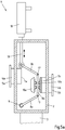
- an actuator 18 is also provided, which is arranged outside the housing 2 and has a rod 19 which can be displaced in the longitudinal direction and is guided into the housing 2. There the rod 19 is connected to the end of the third part 8c of the arm 8. The longitudinal movement of the Rod 19 of the actuator 18 is therefore transmitted from the third part 8c of the arm 8 via the joint 17 'first to the second part 8b of the arm 8 and then via the joint 17 to the first part 8a of the arm 8 which is pivotably mounted about the axis of rotation 9 ,
- the in Fig. 5a and Fig. 5b shown device take two switching positions: In the first, in Fig. 5a Switch position shown, the rod 19 of the actuator 18 is extended far, so that the second part 8b of the arm 8 diverts to the right in the direction of the outlet 4b, the closure element 10b closes the outlet 4b.
- the second switching position shown in FIG. 5b provides that the rod 19 of the actuator 18 is drawn in far, so that the second part 8b of the arm 8 is pulled to the left in the direction of the outlet 4a, the closure element 10a closing the outlet 4a.
- a neutral switching position is possible, in which both outlets 4a, 4b remain open.
- Fig. 5a and Fig. 5b shown embodiment of the device 1 a total of 3 connections (one inlet 3 and two outlets 4a, 4b) are present and - apart from the neutral switching position - two switching positions are possible, it is a 3/2-way valve.
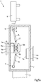
- FIG. 6 A sixth embodiment of a device 1 according to the invention is shown in plan view.
- the already related to 1a to 5b Areas of the device 1 described are in Fig. 6 provided with corresponding reference numerals.
- the sixth embodiment of the device 1 differs from the embodiments shown above in particular in that three arms 8, 8 ', 8 "are provided, which are movably connected to the housing 2 via a common linear guide 20. While the common linear guide 20 is fixed with is connected to the housing, each of the arms 8, 8 ', 8 "can be displaced in the longitudinal direction relative to the linear guide 20 (represented by an arrow in each case).
- the three outlets 4a, 4b, 4c are closed and opened by moving the arms 8, 8 ', 8 "radially outwards or inwards in the longitudinal direction
- a closure element 10a, 10b, 10c is arranged at each end of the arms 8, 8 ', 8 ", and is pressed in this way onto the end 7a, 7b, 7c, projecting into the housing 2, of the outlet 4a, 4b, 4c assigned to it
- the closure elements 10a, 10b, 10c are each connected to the arms 8, 8 ', 8 "via a joint 17", in particular a ball joint.
- closure elements 10a, 10b, 10c are already attached to the arms previously described manner aligned by spring elements 11a, 11b, 11c, which are arranged under prestress between the closure elements 10a, 10b, 10c and a shoulder of the arms 8, 8 ', 8 "provided for this purpose.
- the three arms 8, 8 ', 8 can be moved independently of one another in their longitudinal direction, so that the sixth embodiment of the device 1 can assume a multiplicity of switching positions.
- the linear movement of the arms 8, 8', 8" is preferably related to that Rotational movement of an adjusting disc 21 coupled, which is rotatably mounted about an axis of rotation 22 in the housing 2.
- each arm 8, 8 ′, 8 ′′ a guide element designed as a wheel 23 and arranged in the plane of the adjusting disk 21, which on rotation of the adjusting disk 21 on an inwardly directed contour 24 Adjusting disk 21 rolls or slides and thereby presses the arm 8, 8 ', 8 "and the closure element 10a, 10b, 10c attached to it in the radial direction against a spring pressure or allows it to come out again in the radial direction as a result of the spring pressure.
- Detent points can be provided on the contour 24 of the adjusting disk 21, which represent a defined position for the wheels 23.
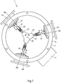
- Fig. 7 finally shows a seventh embodiment of a device 1 according to the invention in plan view.
- the already related to 1a to 6 Areas of the device 1 described are in Fig. 7 provided with corresponding reference numerals.
- the seventh embodiment of the device 1 differs from the sixth embodiment in that the arms 8, 8 ', 8 "are actuated.
- the common, centrally arranged linear guide 20 is omitted; the arms 8, 8', 8" are instead over separate, outside Linear guides 25 movably connected to the housing 2. While each linear guide 25 is fixedly connected to the housing 2, each of the arms 8, 8 ′, 8 ′′ can be displaced in the longitudinal direction relative to the linear guide 25 (represented by an arrow).
- the linear one Movement of the arms 8, 8 ', 8 is coupled to the rotational movement of the adjusting disc 21, which in turn is rotatably mounted about an axis of rotation 22 in the housing 2 (represented by an arrow).
- a guide element designed as a wheel 23 is attached to each arm 8, 8 ′, 8 ′′ and rolls or slides on the contour 24 of the adjusting disk 21 when the adjusting disk 21 rotates.
- the contour 24 in the seventh embodiment is directed outwards, so that the wheel 23 rolling or sliding on it, the arm 8, 8 ', 8 "and the closure element 10a, 10b, 10c attached thereto in the radial direction against one another Pushes the spring pressure outwards or causes it to come inwards again in the radial direction due to the spring pressure.
- the adjusting disk 21 therefore has similarities to a camshaft in the seventh embodiment.
- the device 1 - apart from the spring elements 11a, 11b, 11c - can be dispensed with additional springs.
- the adjusting disks 21 can be configured in such a way that the wheels 23 slide on both sides on a correspondingly shaped contour 24 of the adjusting disks 21 and can thus be positively guided radially inwards and radially outwards.
- inlets 3 and outlets 4a, 4b, 4a ', 4b', 4c can be interchanged as desired; in particular, two or more inlets 3 can also be provided, which can also be open at the same time.
Landscapes
- Engineering & Computer Science (AREA)
- General Engineering & Computer Science (AREA)
- Mechanical Engineering (AREA)
- Multiple-Way Valves (AREA)
- Lift Valve (AREA)
- Flow Control (AREA)
- Investigating Or Analysing Biological Materials (AREA)
- Food Preservation Except Freezing, Refrigeration, And Drying (AREA)
Priority Applications (1)
| Application Number | Priority Date | Filing Date | Title |
|---|---|---|---|
| PL15717108T PL3137795T3 (pl) | 2014-04-29 | 2015-03-31 | Urządzenie do sterowania lub regulacji natężenia przepływu i/albo kierunku przepływu płynów |
Applications Claiming Priority (2)
| Application Number | Priority Date | Filing Date | Title |
|---|---|---|---|
| DE102014106010.5A DE102014106010A1 (de) | 2014-04-29 | 2014-04-29 | Vorrichtung zur Steuerung oder Regelung der Durchflussmenge und/oder Durchflussrichtung von Fluiden |
| PCT/EP2015/056998 WO2015165676A1 (de) | 2014-04-29 | 2015-03-31 | Vorrichtung zur steuerung oder regelung der durchflussmenge und/oder durchflussrichtung von fluiden |
Publications (2)
| Publication Number | Publication Date |
|---|---|
| EP3137795A1 EP3137795A1 (de) | 2017-03-08 |
| EP3137795B1 true EP3137795B1 (de) | 2020-01-15 |
Family
ID=52988016
Family Applications (1)
| Application Number | Title | Priority Date | Filing Date |
|---|---|---|---|
| EP15717108.3A Active EP3137795B1 (de) | 2014-04-29 | 2015-03-31 | Vorrichtung zur steuerung oder regelung der durchflussmenge und/oder durchflussrichtung von fluiden |
Country Status (12)
| Country | Link |
|---|---|
| US (1) | US10627000B2 (pl) |
| EP (1) | EP3137795B1 (pl) |
| JP (1) | JP2017516037A (pl) |
| CN (1) | CN106461099B (pl) |
| AU (1) | AU2015252302A1 (pl) |
| BR (1) | BR112016024697A2 (pl) |
| DE (1) | DE102014106010A1 (pl) |
| ES (1) | ES2771858T3 (pl) |
| MX (1) | MX2016013252A (pl) |
| PL (1) | PL3137795T3 (pl) |
| RU (1) | RU2016142437A (pl) |
| WO (1) | WO2015165676A1 (pl) |
Families Citing this family (9)
| Publication number | Priority date | Publication date | Assignee | Title |
|---|---|---|---|---|
| US10711788B2 (en) | 2015-12-17 | 2020-07-14 | Wayne/Scott Fetzer Company | Integrated sump pump controller with status notifications |
| EP3236121B1 (de) * | 2016-04-21 | 2020-09-16 | Leser GmbH & Co. KG | Wechselventil für eine sicherheitsventilanordnung und sicherheitsventilanordnung |
| USD893552S1 (en) | 2017-06-21 | 2020-08-18 | Wayne/Scott Fetzer Company | Pump components |
| USD890211S1 (en) | 2018-01-11 | 2020-07-14 | Wayne/Scott Fetzer Company | Pump components |
| CN110307070B (zh) * | 2019-06-27 | 2021-11-16 | 三一重型装备有限公司 | 气体换向装置和内燃机 |
| CN111501966B (zh) * | 2020-04-22 | 2021-03-26 | 广东中帆建设有限公司 | 一种预制装配式雨污水检查井流槽 |
| US20220381205A1 (en) * | 2021-05-25 | 2022-12-01 | Faurecia Emissions Control Technologies, Usa, Llc | Valve assembly for vehicle exhaust system |
| DE102023119886A1 (de) * | 2023-07-26 | 2025-01-30 | Iva Schmetz Gmbh | Vakuumkammerofen zur Wärmebehandlung von metallischen Werkstücken |
| DE102023132328A1 (de) * | 2023-11-21 | 2025-05-22 | Schaeffler Technologies AG & Co. KG | 3/2-Wegeventil eines Gasleitsystems und Abgasbehandlungsanlage |
Family Cites Families (29)
| Publication number | Priority date | Publication date | Assignee | Title |
|---|---|---|---|---|
| US1858246A (en) * | 1930-05-07 | 1932-05-17 | Nat Supply Co | Pump manifold |
| US2244986A (en) * | 1940-02-28 | 1941-06-10 | Phillips B Drane | Diverting valve |
| US2441253A (en) | 1944-10-30 | 1948-05-11 | Rohim Mfg Company Inc | Valve |
| US2486825A (en) | 1944-12-26 | 1949-11-01 | Baufre William Lane De | Nonreturn valve for low temperature |
| US2828820A (en) * | 1957-05-13 | 1958-04-01 | Harvel Res Corp | Novel compositions of matter and methods and steps of making and using the same |
| DK103927C (da) * | 1962-06-19 | 1966-03-07 | Ewers & Miesner Hartgusswerk U | Hurtigtlukkende beskyttelsesindretning til ventilationskanaler i luftbeskyttelsesrum. |
| DE2201601A1 (de) * | 1972-01-14 | 1973-07-19 | Volkswagenwerk Ag | Zweiwege-klappenventil |
| JPS5269638U (pl) * | 1975-11-19 | 1977-05-24 | ||
| JPS5554114Y2 (pl) * | 1976-05-11 | 1980-12-15 | ||
| JPS53143221U (pl) * | 1977-04-19 | 1978-11-11 | ||
| LU77487A1 (pl) * | 1977-06-06 | 1977-09-22 | ||
| JPH0517514Y2 (pl) * | 1988-01-25 | 1993-05-11 | ||
| FI84294C (fi) | 1989-12-20 | 1991-11-11 | Oras Oy | Termostatventil. |
| DE9003542U1 (de) | 1990-03-27 | 1990-05-31 | Skw Trostberg Ag, 8223 Trostberg | Dreiwegeklappe |
| FR2701292B1 (fr) | 1993-02-05 | 1995-03-10 | Renault | Dispositif obturateur pour circuit d'échappement de moteur à combustion interne. |
| JPH07224633A (ja) | 1994-02-16 | 1995-08-22 | Nippon Soken Inc | バルブおよびそれを用いた排気浄化装置 |
| JP3084548B2 (ja) * | 1995-01-31 | 2000-09-04 | 日立造船株式会社 | 切換三方弁 |
| JPH10121996A (ja) | 1996-10-18 | 1998-05-12 | Sumitomo Electric Ind Ltd | 三方弁及びそれを用いた排気ガス処理装置 |
| US5950987A (en) * | 1997-06-06 | 1999-09-14 | Tetra Laval Holdings & Finance, Sa | In-line lever actuated valve |
| DE19831272A1 (de) | 1998-07-13 | 2000-01-20 | Grohe Armaturen Friedrich | Mischventil |
| DE10053850A1 (de) | 2000-10-30 | 2002-05-08 | Bosch Gmbh Robert | Exzenterventil |
| DE10360706A1 (de) * | 2003-12-19 | 2005-07-14 | Aweco Appliance Systems Gmbh & Co. Kg | Ventil und Verfahren zum Herstellen eines Ventils |
| FR2900455B1 (fr) | 2006-04-26 | 2008-07-04 | Valeo Sys Controle Moteur Sas | Vanne a deux papillons actionnes par un moteur commun |
| JP3124080U (ja) | 2006-05-25 | 2006-08-03 | 株式会社カセットミュージアム | 音声ガイド |
| US20080169026A1 (en) * | 2007-01-11 | 2008-07-17 | Sanchez Terry J | Fluid diverter and method |
| CN101265986B (zh) | 2008-04-25 | 2010-08-25 | 浪达科技(深圳)有限公司 | 低压降高温气体换向阀的密封结构 |
| DE102010018674B4 (de) * | 2010-04-28 | 2023-07-06 | Dr. Ing. H.C. F. Porsche Aktiengesellschaft | Vorrichtung zur Führung eines Abgasstroms |
| CN201875199U (zh) | 2010-11-09 | 2011-06-22 | 中国石油化工股份有限公司 | 一种三通换向阀 |
| CN203532850U (zh) | 2013-09-03 | 2014-04-09 | 扬州高标机械有限公司 | 一种余热发电大型烟气换向三通挡板阀 |
-
2014
- 2014-04-29 DE DE102014106010.5A patent/DE102014106010A1/de not_active Ceased
-
2015
- 2015-03-31 RU RU2016142437A patent/RU2016142437A/ru not_active Application Discontinuation
- 2015-03-31 AU AU2015252302A patent/AU2015252302A1/en not_active Abandoned
- 2015-03-31 MX MX2016013252A patent/MX2016013252A/es unknown
- 2015-03-31 CN CN201580021701.6A patent/CN106461099B/zh not_active Expired - Fee Related
- 2015-03-31 BR BR112016024697A patent/BR112016024697A2/pt not_active Application Discontinuation
- 2015-03-31 EP EP15717108.3A patent/EP3137795B1/de active Active
- 2015-03-31 PL PL15717108T patent/PL3137795T3/pl unknown
- 2015-03-31 WO PCT/EP2015/056998 patent/WO2015165676A1/de not_active Ceased
- 2015-03-31 ES ES15717108T patent/ES2771858T3/es active Active
- 2015-03-31 US US15/307,635 patent/US10627000B2/en not_active Expired - Fee Related
- 2015-03-31 JP JP2016565218A patent/JP2017516037A/ja active Pending
Non-Patent Citations (1)
| Title |
|---|
| None * |
Also Published As
| Publication number | Publication date |
|---|---|
| AU2015252302A1 (en) | 2016-09-29 |
| EP3137795A1 (de) | 2017-03-08 |
| RU2016142437A3 (pl) | 2018-10-18 |
| DE102014106010A1 (de) | 2015-10-29 |
| MX2016013252A (es) | 2017-01-26 |
| CN106461099B (zh) | 2020-05-15 |
| BR112016024697A2 (pt) | 2017-08-15 |
| CN106461099A (zh) | 2017-02-22 |
| WO2015165676A1 (de) | 2015-11-05 |
| JP2017516037A (ja) | 2017-06-15 |
| ES2771858T3 (es) | 2020-07-07 |
| US10627000B2 (en) | 2020-04-21 |
| RU2016142437A (ru) | 2018-04-28 |
| PL3137795T3 (pl) | 2020-06-29 |
| US20170051838A1 (en) | 2017-02-23 |
Similar Documents
| Publication | Publication Date | Title |
|---|---|---|
| EP3137795B1 (de) | Vorrichtung zur steuerung oder regelung der durchflussmenge und/oder durchflussrichtung von fluiden | |
| EP0916046B1 (de) | Doppelsitzventil | |
| DE102011116627B3 (de) | Betätigungsvorrichtung für einen drehbaren Verschlussteil eines Ventils | |
| EP2749798B1 (de) | Vakuumschieberventil | |
| DE3224387C2 (pl) | ||
| EP2252819B1 (de) | Vorrichtung zur verbindung eines ventilgehäuses mit einem stellantrieb bei einem als hubventil fungierenden prozessventil | |
| DE2916984A1 (de) | Sitz fuer ein absperrelement eines absperrorgans und absperrorgan mit einem solchen sitz | |
| DE69314188T2 (de) | Antriebselement zum transfer von vor- und rückwärtsrotations-bewegungen | |
| DE102016103723A1 (de) | Vorrichtung zum Bewegen eines Ventilelements, Ventil mit dieser Vorrichtung und entsprechendes Betätigungsverfahren | |
| WO2011088482A1 (de) | Vakuumventil | |
| EP3919419A1 (de) | Vorrichtung zum halten eines behälters und behälterbehandlungsvorrichtung | |
| EP2397727A1 (de) | Mehrteiliger Ventilteller | |
| DE2457230B2 (de) | Hahn zum Absperren und Steuern von Hochtemperatur-Strömungsmedien | |
| DE2822982C2 (de) | Ventil | |
| DE102009025290A1 (de) | Doppelklappenvorrichtung zum umweltdichten Verbinden zweier Behältnisse | |
| EP3236121B1 (de) | Wechselventil für eine sicherheitsventilanordnung und sicherheitsventilanordnung | |
| DE102006040311A1 (de) | Durchflussratensteuerventil | |
| DE102010033429A1 (de) | Industrieroboter | |
| EP2400190B1 (de) | Drehkegelventil | |
| DE102006053373B3 (de) | Doppelplattenschieber | |
| EP3489460B1 (de) | Ventil für eine dampfturbine | |
| DE3509289C1 (de) | Schnellschlußvorrichtung für strömende Medien | |
| EP2497979B1 (de) | Verwendung antimikrobieller Materialien und Beschichtungen in Prozesskomponenten | |
| DE102014113511A1 (de) | Flüssigkeitsventil und dessen modulare Spindel-Verpackungs-Konstruktion | |
| EP3406953B1 (de) | Wanddurchführung für zwei rohrleitungen |
Legal Events
| Date | Code | Title | Description |
|---|---|---|---|
| STAA | Information on the status of an ep patent application or granted ep patent |
Free format text: STATUS: THE INTERNATIONAL PUBLICATION HAS BEEN MADE |
|
| PUAI | Public reference made under article 153(3) epc to a published international application that has entered the european phase |
Free format text: ORIGINAL CODE: 0009012 |
|
| STAA | Information on the status of an ep patent application or granted ep patent |
Free format text: STATUS: REQUEST FOR EXAMINATION WAS MADE |
|
| 17P | Request for examination filed |
Effective date: 20160912 |
|
| AK | Designated contracting states |
Kind code of ref document: A1 Designated state(s): AL AT BE BG CH CY CZ DE DK EE ES FI FR GB GR HR HU IE IS IT LI LT LU LV MC MK MT NL NO PL PT RO RS SE SI SK SM TR |
|
| AX | Request for extension of the european patent |
Extension state: BA ME |
|
| DAV | Request for validation of the european patent (deleted) | ||
| DAX | Request for extension of the european patent (deleted) | ||
| GRAP | Despatch of communication of intention to grant a patent |
Free format text: ORIGINAL CODE: EPIDOSNIGR1 |
|
| STAA | Information on the status of an ep patent application or granted ep patent |
Free format text: STATUS: GRANT OF PATENT IS INTENDED |
|
| INTG | Intention to grant announced |
Effective date: 20190816 |
|
| GRAS | Grant fee paid |
Free format text: ORIGINAL CODE: EPIDOSNIGR3 |
|
| GRAA | (expected) grant |
Free format text: ORIGINAL CODE: 0009210 |
|
| STAA | Information on the status of an ep patent application or granted ep patent |
Free format text: STATUS: THE PATENT HAS BEEN GRANTED |
|
| AK | Designated contracting states |
Kind code of ref document: B1 Designated state(s): AL AT BE BG CH CY CZ DE DK EE ES FI FR GB GR HR HU IE IS IT LI LT LU LV MC MK MT NL NO PL PT RO RS SE SI SK SM TR |
|
| REG | Reference to a national code |
Ref country code: CH Ref legal event code: EP Ref country code: GB Ref legal event code: FG4D Free format text: NOT ENGLISH |
|
| REG | Reference to a national code |
Ref country code: IE Ref legal event code: FG4D Free format text: LANGUAGE OF EP DOCUMENT: GERMAN |
|
| REG | Reference to a national code |
Ref country code: DE Ref legal event code: R096 Ref document number: 502015011531 Country of ref document: DE |
|
| REG | Reference to a national code |
Ref country code: AT Ref legal event code: REF Ref document number: 1225447 Country of ref document: AT Kind code of ref document: T Effective date: 20200215 |
|
| REG | Reference to a national code |
Ref country code: NL Ref legal event code: MP Effective date: 20200115 |
|
| REG | Reference to a national code |
Ref country code: ES Ref legal event code: FG2A Ref document number: 2771858 Country of ref document: ES Kind code of ref document: T3 Effective date: 20200707 |
|
| REG | Reference to a national code |
Ref country code: LT Ref legal event code: MG4D |
|
| PG25 | Lapsed in a contracting state [announced via postgrant information from national office to epo] |
Ref country code: RS Free format text: LAPSE BECAUSE OF FAILURE TO SUBMIT A TRANSLATION OF THE DESCRIPTION OR TO PAY THE FEE WITHIN THE PRESCRIBED TIME-LIMIT Effective date: 20200115 Ref country code: NL Free format text: LAPSE BECAUSE OF FAILURE TO SUBMIT A TRANSLATION OF THE DESCRIPTION OR TO PAY THE FEE WITHIN THE PRESCRIBED TIME-LIMIT Effective date: 20200115 Ref country code: PT Free format text: LAPSE BECAUSE OF FAILURE TO SUBMIT A TRANSLATION OF THE DESCRIPTION OR TO PAY THE FEE WITHIN THE PRESCRIBED TIME-LIMIT Effective date: 20200607 Ref country code: NO Free format text: LAPSE BECAUSE OF FAILURE TO SUBMIT A TRANSLATION OF THE DESCRIPTION OR TO PAY THE FEE WITHIN THE PRESCRIBED TIME-LIMIT Effective date: 20200415 Ref country code: FI Free format text: LAPSE BECAUSE OF FAILURE TO SUBMIT A TRANSLATION OF THE DESCRIPTION OR TO PAY THE FEE WITHIN THE PRESCRIBED TIME-LIMIT Effective date: 20200115 |
|
| PG25 | Lapsed in a contracting state [announced via postgrant information from national office to epo] |
Ref country code: HR Free format text: LAPSE BECAUSE OF FAILURE TO SUBMIT A TRANSLATION OF THE DESCRIPTION OR TO PAY THE FEE WITHIN THE PRESCRIBED TIME-LIMIT Effective date: 20200115 Ref country code: IS Free format text: LAPSE BECAUSE OF FAILURE TO SUBMIT A TRANSLATION OF THE DESCRIPTION OR TO PAY THE FEE WITHIN THE PRESCRIBED TIME-LIMIT Effective date: 20200515 Ref country code: BG Free format text: LAPSE BECAUSE OF FAILURE TO SUBMIT A TRANSLATION OF THE DESCRIPTION OR TO PAY THE FEE WITHIN THE PRESCRIBED TIME-LIMIT Effective date: 20200415 Ref country code: GR Free format text: LAPSE BECAUSE OF FAILURE TO SUBMIT A TRANSLATION OF THE DESCRIPTION OR TO PAY THE FEE WITHIN THE PRESCRIBED TIME-LIMIT Effective date: 20200416 Ref country code: LV Free format text: LAPSE BECAUSE OF FAILURE TO SUBMIT A TRANSLATION OF THE DESCRIPTION OR TO PAY THE FEE WITHIN THE PRESCRIBED TIME-LIMIT Effective date: 20200115 Ref country code: SE Free format text: LAPSE BECAUSE OF FAILURE TO SUBMIT A TRANSLATION OF THE DESCRIPTION OR TO PAY THE FEE WITHIN THE PRESCRIBED TIME-LIMIT Effective date: 20200115 |
|
| REG | Reference to a national code |
Ref country code: DE Ref legal event code: R097 Ref document number: 502015011531 Country of ref document: DE |
|
| PG25 | Lapsed in a contracting state [announced via postgrant information from national office to epo] |
Ref country code: RO Free format text: LAPSE BECAUSE OF FAILURE TO SUBMIT A TRANSLATION OF THE DESCRIPTION OR TO PAY THE FEE WITHIN THE PRESCRIBED TIME-LIMIT Effective date: 20200115 Ref country code: SK Free format text: LAPSE BECAUSE OF FAILURE TO SUBMIT A TRANSLATION OF THE DESCRIPTION OR TO PAY THE FEE WITHIN THE PRESCRIBED TIME-LIMIT Effective date: 20200115 Ref country code: CZ Free format text: LAPSE BECAUSE OF FAILURE TO SUBMIT A TRANSLATION OF THE DESCRIPTION OR TO PAY THE FEE WITHIN THE PRESCRIBED TIME-LIMIT Effective date: 20200115 Ref country code: SM Free format text: LAPSE BECAUSE OF FAILURE TO SUBMIT A TRANSLATION OF THE DESCRIPTION OR TO PAY THE FEE WITHIN THE PRESCRIBED TIME-LIMIT Effective date: 20200115 Ref country code: EE Free format text: LAPSE BECAUSE OF FAILURE TO SUBMIT A TRANSLATION OF THE DESCRIPTION OR TO PAY THE FEE WITHIN THE PRESCRIBED TIME-LIMIT Effective date: 20200115 Ref country code: DK Free format text: LAPSE BECAUSE OF FAILURE TO SUBMIT A TRANSLATION OF THE DESCRIPTION OR TO PAY THE FEE WITHIN THE PRESCRIBED TIME-LIMIT Effective date: 20200115 Ref country code: LT Free format text: LAPSE BECAUSE OF FAILURE TO SUBMIT A TRANSLATION OF THE DESCRIPTION OR TO PAY THE FEE WITHIN THE PRESCRIBED TIME-LIMIT Effective date: 20200115 Ref country code: MC Free format text: LAPSE BECAUSE OF FAILURE TO SUBMIT A TRANSLATION OF THE DESCRIPTION OR TO PAY THE FEE WITHIN THE PRESCRIBED TIME-LIMIT Effective date: 20200115 |
|
| REG | Reference to a national code |
Ref country code: CH Ref legal event code: PL |
|
| PLBE | No opposition filed within time limit |
Free format text: ORIGINAL CODE: 0009261 |
|
| STAA | Information on the status of an ep patent application or granted ep patent |
Free format text: STATUS: NO OPPOSITION FILED WITHIN TIME LIMIT |
|
| 26N | No opposition filed |
Effective date: 20201016 |
|
| REG | Reference to a national code |
Ref country code: BE Ref legal event code: MM Effective date: 20200331 |
|
| PG25 | Lapsed in a contracting state [announced via postgrant information from national office to epo] |
Ref country code: LU Free format text: LAPSE BECAUSE OF NON-PAYMENT OF DUE FEES Effective date: 20200331 |
|
| PG25 | Lapsed in a contracting state [announced via postgrant information from national office to epo] |
Ref country code: CH Free format text: LAPSE BECAUSE OF NON-PAYMENT OF DUE FEES Effective date: 20200331 Ref country code: LI Free format text: LAPSE BECAUSE OF NON-PAYMENT OF DUE FEES Effective date: 20200331 Ref country code: IE Free format text: LAPSE BECAUSE OF NON-PAYMENT OF DUE FEES Effective date: 20200331 |
|
| PG25 | Lapsed in a contracting state [announced via postgrant information from national office to epo] |
Ref country code: SI Free format text: LAPSE BECAUSE OF FAILURE TO SUBMIT A TRANSLATION OF THE DESCRIPTION OR TO PAY THE FEE WITHIN THE PRESCRIBED TIME-LIMIT Effective date: 20200115 Ref country code: BE Free format text: LAPSE BECAUSE OF NON-PAYMENT OF DUE FEES Effective date: 20200331 |
|
| PGFP | Annual fee paid to national office [announced via postgrant information from national office to epo] |
Ref country code: FR Payment date: 20210318 Year of fee payment: 7 Ref country code: IT Payment date: 20210324 Year of fee payment: 7 |
|
| REG | Reference to a national code |
Ref country code: AT Ref legal event code: MM01 Ref document number: 1225447 Country of ref document: AT Kind code of ref document: T Effective date: 20200331 |
|
| PGFP | Annual fee paid to national office [announced via postgrant information from national office to epo] |
Ref country code: GB Payment date: 20210318 Year of fee payment: 7 Ref country code: PL Payment date: 20210326 Year of fee payment: 7 Ref country code: TR Payment date: 20210222 Year of fee payment: 7 Ref country code: DE Payment date: 20210318 Year of fee payment: 7 |
|
| PG25 | Lapsed in a contracting state [announced via postgrant information from national office to epo] |
Ref country code: AT Free format text: LAPSE BECAUSE OF NON-PAYMENT OF DUE FEES Effective date: 20200331 |
|
| PGFP | Annual fee paid to national office [announced via postgrant information from national office to epo] |
Ref country code: ES Payment date: 20210420 Year of fee payment: 7 |
|
| PG25 | Lapsed in a contracting state [announced via postgrant information from national office to epo] |
Ref country code: MT Free format text: LAPSE BECAUSE OF FAILURE TO SUBMIT A TRANSLATION OF THE DESCRIPTION OR TO PAY THE FEE WITHIN THE PRESCRIBED TIME-LIMIT Effective date: 20200115 Ref country code: CY Free format text: LAPSE BECAUSE OF FAILURE TO SUBMIT A TRANSLATION OF THE DESCRIPTION OR TO PAY THE FEE WITHIN THE PRESCRIBED TIME-LIMIT Effective date: 20200115 |
|
| PG25 | Lapsed in a contracting state [announced via postgrant information from national office to epo] |
Ref country code: MK Free format text: LAPSE BECAUSE OF FAILURE TO SUBMIT A TRANSLATION OF THE DESCRIPTION OR TO PAY THE FEE WITHIN THE PRESCRIBED TIME-LIMIT Effective date: 20200115 Ref country code: AL Free format text: LAPSE BECAUSE OF FAILURE TO SUBMIT A TRANSLATION OF THE DESCRIPTION OR TO PAY THE FEE WITHIN THE PRESCRIBED TIME-LIMIT Effective date: 20200115 |
|
| REG | Reference to a national code |
Ref country code: DE Ref legal event code: R119 Ref document number: 502015011531 Country of ref document: DE |
|
| GBPC | Gb: european patent ceased through non-payment of renewal fee |
Effective date: 20220331 |
|
| PG25 | Lapsed in a contracting state [announced via postgrant information from national office to epo] |
Ref country code: GB Free format text: LAPSE BECAUSE OF NON-PAYMENT OF DUE FEES Effective date: 20220331 Ref country code: FR Free format text: LAPSE BECAUSE OF NON-PAYMENT OF DUE FEES Effective date: 20220331 Ref country code: DE Free format text: LAPSE BECAUSE OF NON-PAYMENT OF DUE FEES Effective date: 20221001 |
|
| REG | Reference to a national code |
Ref country code: ES Ref legal event code: FD2A Effective date: 20230509 |
|
| PG25 | Lapsed in a contracting state [announced via postgrant information from national office to epo] |
Ref country code: IT Free format text: LAPSE BECAUSE OF NON-PAYMENT OF DUE FEES Effective date: 20220331 |
|
| PG25 | Lapsed in a contracting state [announced via postgrant information from national office to epo] |
Ref country code: ES Free format text: LAPSE BECAUSE OF NON-PAYMENT OF DUE FEES Effective date: 20220401 |
|
| PG25 | Lapsed in a contracting state [announced via postgrant information from national office to epo] |
Ref country code: PL Free format text: LAPSE BECAUSE OF NON-PAYMENT OF DUE FEES Effective date: 20220331 |