EP3137397B1 - Antriebseinheit - Google Patents
Antriebseinheit Download PDFInfo
- Publication number
- EP3137397B1 EP3137397B1 EP15726108.2A EP15726108A EP3137397B1 EP 3137397 B1 EP3137397 B1 EP 3137397B1 EP 15726108 A EP15726108 A EP 15726108A EP 3137397 B1 EP3137397 B1 EP 3137397B1
- Authority
- EP
- European Patent Office
- Prior art keywords
- section
- carriage
- barrel
- drive
- rotation
- Prior art date
- Legal status (The legal status is an assumption and is not a legal conclusion. Google has not performed a legal analysis and makes no representation as to the accuracy of the status listed.)
- Active
Links
Images


Classifications
-
- B—PERFORMING OPERATIONS; TRANSPORTING
- B65—CONVEYING; PACKING; STORING; HANDLING THIN OR FILAMENTARY MATERIAL
- B65G—TRANSPORT OR STORAGE DEVICES, e.g. CONVEYORS FOR LOADING OR TIPPING, SHOP CONVEYOR SYSTEMS OR PNEUMATIC TUBE CONVEYORS
- B65G35/00—Mechanical conveyors not otherwise provided for
- B65G35/06—Mechanical conveyors not otherwise provided for comprising a load-carrier moving along a path, e.g. a closed path, and adapted to be engaged by any one of a series of traction elements spaced along the path
- B65G35/063—Mechanical conveyors not otherwise provided for comprising a load-carrier moving along a path, e.g. a closed path, and adapted to be engaged by any one of a series of traction elements spaced along the path the traction element being a rotating bar or tube
- B65G35/066—Mechanical conveyors not otherwise provided for comprising a load-carrier moving along a path, e.g. a closed path, and adapted to be engaged by any one of a series of traction elements spaced along the path the traction element being a rotating bar or tube the bar or the tube being provided with a helical or annular channel
-
- B—PERFORMING OPERATIONS; TRANSPORTING
- B23—MACHINE TOOLS; METAL-WORKING NOT OTHERWISE PROVIDED FOR
- B23Q—DETAILS, COMPONENTS, OR ACCESSORIES FOR MACHINE TOOLS, e.g. ARRANGEMENTS FOR COPYING OR CONTROLLING; MACHINE TOOLS IN GENERAL CHARACTERISED BY THE CONSTRUCTION OF PARTICULAR DETAILS OR COMPONENTS; COMBINATIONS OR ASSOCIATIONS OF METAL-WORKING MACHINES, NOT DIRECTED TO A PARTICULAR RESULT
- B23Q5/00—Driving or feeding mechanisms; Control arrangements therefor
- B23Q5/22—Feeding members carrying tools or work
- B23Q5/34—Feeding other members supporting tools or work, e.g. saddles, tool-slides, through mechanical transmission
- B23Q5/341—Feeding other members supporting tools or work, e.g. saddles, tool-slides, through mechanical transmission cam-operated
-
- B—PERFORMING OPERATIONS; TRANSPORTING
- B23—MACHINE TOOLS; METAL-WORKING NOT OTHERWISE PROVIDED FOR
- B23Q—DETAILS, COMPONENTS, OR ACCESSORIES FOR MACHINE TOOLS, e.g. ARRANGEMENTS FOR COPYING OR CONTROLLING; MACHINE TOOLS IN GENERAL CHARACTERISED BY THE CONSTRUCTION OF PARTICULAR DETAILS OR COMPONENTS; COMBINATIONS OR ASSOCIATIONS OF METAL-WORKING MACHINES, NOT DIRECTED TO A PARTICULAR RESULT
- B23Q7/00—Arrangements for handling work specially combined with or arranged in, or specially adapted for use in connection with, machine tools, e.g. for conveying, loading, positioning, discharging, sorting
- B23Q7/14—Arrangements for handling work specially combined with or arranged in, or specially adapted for use in connection with, machine tools, e.g. for conveying, loading, positioning, discharging, sorting co-ordinated in production lines
- B23Q7/1426—Arrangements for handling work specially combined with or arranged in, or specially adapted for use in connection with, machine tools, e.g. for conveying, loading, positioning, discharging, sorting co-ordinated in production lines with work holders not rigidly fixed to the transport devices
- B23Q7/1463—Arrangements for handling work specially combined with or arranged in, or specially adapted for use in connection with, machine tools, e.g. for conveying, loading, positioning, discharging, sorting co-ordinated in production lines with work holders not rigidly fixed to the transport devices using rotary driving means
-
- B—PERFORMING OPERATIONS; TRANSPORTING
- B61—RAILWAYS
- B61B—RAILWAY SYSTEMS; EQUIPMENT THEREFOR NOT OTHERWISE PROVIDED FOR
- B61B13/00—Other railway systems
- B61B13/12—Systems with propulsion devices between or alongside the rails, e.g. pneumatic systems
- B61B13/125—Systems with propulsion devices between or alongside the rails, e.g. pneumatic systems the propulsion device being a rotating shaft or the like
-
- B—PERFORMING OPERATIONS; TRANSPORTING
- B65—CONVEYING; PACKING; STORING; HANDLING THIN OR FILAMENTARY MATERIAL
- B65G—TRANSPORT OR STORAGE DEVICES, e.g. CONVEYORS FOR LOADING OR TIPPING, SHOP CONVEYOR SYSTEMS OR PNEUMATIC TUBE CONVEYORS
- B65G23/00—Driving gear for endless conveyors; Belt- or chain-tensioning arrangements
- B65G23/02—Belt- or chain-engaging elements
- B65G23/20—Screws
Definitions
- the present invention relates to a drive unit for driving a carriage which can be moved along a transport path with a cam drum drivable for rotational movement, which has a drive groove for engagement of a driver arranged on the carriage, and with a control device for controlling the drive of the carriage.
- Drive units of this kind are used, for example, in assembly and automation technology to move movable carriages with workpieces arranged thereon in a positionally accurate manner to the corresponding processing and / or assembly stations.
- a transfer of the carriages from a separate drive unit-such as a belt drive-to a drive unit with cam drum may be required.
- the WO 80/00559 A1 discloses a generic drive unit according to the preamble of claim 1 and a Vefahren according to the preamble of claim 9, wherein a transport system with intersecting roller conveyors on which containers are conveyed by means of transport screws. The transport screws cooperate with protrusions on the underside of the containers.
- the cam drum has a first drum section and a second drum section separated therefrom, the drum sections being drivable independently of one another and wherein the control device is designed to accelerate the carriage by means of the first drum section following transfer from a separate drive unit and the accelerated carriage supply second drum section.
- the cam drum is thus divided into at least two drum sections, so that two axial sections of the drive groove are rotatable relative to each other.
- the first drum portion for a takeover of a carriage can be moved to a defined rotational position, while the second drum portion thereof unaffected - with even or non-uniform rotation - one or more previous carriage on. After a corresponding acceleration of the carriage, an unhindered transfer of the driver from the first Drum section made on the second drum section.
- the first drum section thus provides, so to speak, a receiving groove which allows unobstructed engagement of a driver out of the movement of the carriage and acceleration of the associated carriage to a desired value.
- the invention therefore allows a considerably higher throughput in transport systems, which have a cam drum drive and an additional separate drive.
- the cam drum drive is provided in particular in sections of the transport path, in which it depends on a high-precision positioning of the carriage, z. B. at stations where a arranged on the carriage workpiece is processed.
- the drive groove in the region of the first drum section comprises a straight section extending parallel to a transport direction and / or parallel to an axis of rotation of the cam drum and an adjoining helically extending section.
- the second barrel portion directly adjoins the first barrel portion to ensure a smooth transition.
- the cam drum has exactly two separately drivable drum sections.
- first and the second drum portion are arranged coaxially to one another, in particular wherein the first drum portion is rotatably mounted on a shaft of the second drum portion. This allows a particularly simple construction.
- a special embodiment of the invention provides that the drive groove in the region of the first drum portion has a helically extending portion which extends over a rotational angle of at most 180 °. Accordingly, the first drum portion may be relatively short in the axial direction to save space.
- the drive groove may have an input-side insertion region in the region of the first drum section, which extends parallel to a transport direction of the carriage and / or parallel to a rotation axis of the cam drum. This allows a smooth and smooth engagement of a moving in the transport direction driver in the drive groove of the cam drum.
- the drive groove may further include a discharge portion in an area adjacent to the second drum portion of the first drum portion, in which a pitch of the drive groove relative to a rotation axis of the cam drum is at least one end portion of a pitch of the drive groove in an adjacent input portion of the second drum portion facing a second drum portion equivalent. This is a smooth transition a carriage from the first drum section to the second drum section ensured.
- Means may be provided for determining an instantaneous rotational speed of the second drum section and optionally the first drum section, the control device being adapted to move the first drum section to a final rotational speed after an acquisition of the carriage from an initial rotational speed, which is preferably zero to accelerate, which corresponds to the current rotational speed of the second drum section.
- a rotation sensor can detect the rotational speed of a shaft of the second drum section and, if appropriate, of the first drum section, output it as a signal and transmit it to the control device. It can thus be ensured with the aid of the control device that the carriage undergoes no sudden acceleration or deceleration when passing to the second drum section.
- the control device may be designed to drive the second drum section to a rotational movement at a constant rotational speed. This is advantageous in that such a drive of the second drum section is easy to implement. But also a variable rotational speed of the second drum section is conceivable.
- Means may also be provided for detecting a current rotational position of the first drum section, wherein the control device is designed to move the first drum section to a predefined rotary position after the carriage has been fed to the second drum section for acceptance of a following carriage.
- a simple rotary encoder can detect the rotational position of the first drum section, output it as a signal and transmit it to the control device. It can thus be ensured by the control that the driver of the carriage on arrival on the first drum portion meets in a desired manner to an insertion opening of the drive groove.
- a rotation sensor which is associated with the second drum portion to detect the relative angular position of the two drum sections and to take into account in the control of the first drum section.
- the drive groove in the region of the first drum section comprises a straight section extending parallel to a transport direction and / or parallel to an axis of rotation of the cam drum and an adjoining helically extending section.
- the straight portion allows jerk-free engagement of an incoming driver while the helical portion serves to accelerate an engaging driver.
- control device is adapted to drive the first drum section to a rotary motion accelerating the carriage as soon as the driver of an accepted carriage has passed from the straight section into the helically extending section.
- a carriage accelerating rotational movement is avoided to prevent undesired pressure forces on the sidewalls of the straight portion of the drive groove.
- the drive groove of the second drum portion may have a constant pitch to ensure a smooth transport movement. If necessary, however, individual areas with a constant or varying slope can be interrupted by so-called Rast réelle, within which the carriage is stationary in spite of further rotating cam drum to z. B. to allow a workpiece machining.
- the pitch of the drive groove in the second drum section may vary.
- the drive groove may have one or more detents and / or sections with different pitches.
- the invention also relates to a method according to claim 9 for transporting objects along a transport path, in which a carriage which can be moved along the transport path and on which at least one object is to be arranged, from a transfer section of the transport path to a process section provided for processing the objects Transport carriage is moved, wherein the carriage is driven in the process section by means of a rotationally driven first cam drum having a drive groove, in which a arranged on the carriage driver engages, and wherein the carriage in the transfer section by means of a separate drive, in particular by means of a belt or linear drive, is driven to a movement.
- the carriage for transferring from the transfer section into the process section is accelerated positively or negatively by means of a second cam drum drivable independently of the first cam drum, the second cam drum being arranged, in particular, directly behind the first cam drum, as seen in the transport direction.
- the second cam drum may be moved to a takeover of a carriage in a defined rotational position, while the first cam drum thereof unaffected under further continuous or varying with time varying rotation one or more previous carriage further. After a corresponding acceleration of the carriage, an unhindered transfer of the driver from the transfer section into the process section can take place.
- an instantaneous rotational speed of the first cam drum is determined, and the second cam drum is accelerated from an initial rotational speed, which is preferably zero, to an end rotational speed which corresponds to the instantaneous rotational speed of the first cam drum.
- an initial rotational speed which is preferably zero
- an end rotational speed which corresponds to the instantaneous rotational speed of the first cam drum.
- An embodiment of the invention provides that a current rotational position of the second cam drum is detected and the second cam drum is rotated after feeding the accelerated carriage to the first cam drum for taking over a subsequent carriage in a predefined rotational position.
- the second cam drum is driven to the carriage accelerating rotational movement as soon as the driver of the carriage from a parallel to a transport direction and / or parallel to a rotational axis of the second cam drum extending straight portion of a drive groove of the second cam drum in an adjoining helical extending portion of the drive groove has passed.
- the straight portion so a rotational movement is avoided to prevent unwanted pressure forces on the side walls of the straight portion of the drive groove.
- the rotational position of the first cam drum is detected by means of a corresponding sensor in order to influence the rotational movement of the first cam drum so that the two cam drums are synchronized for the transfer of the carriage.
- the invention relates to a transport device for transporting objects along a transport path with the features of claim 14, comprising at least one movable carriage along the transport path, which is adapted to receive at least one object to be transported, and with means for controlled driving of the carriage.
- Transport devices of this type are used, inter alia, in assembly and automation technology to move workpieces to a processing and / or assembly station.
- One or more workpieces are arranged on the carriage, which z. B. is guided displaceably on a rail assembly.
- the transport path defined by the rail arrangement may be open or closed and comprise straight and curved sections. Frequently, the workpieces are successively fed to several processing and / or assembly stations.
- a cam drum may be provided as described above.
- An advantage of a drive by means of a cam drum is the associated high positioning accuracy. However, with such a drive generally no high speeds can be achieved. Within a processing and / or assembly station, this is generally not a big disadvantage, since the corresponding trajectories are usually relatively short. In many applications, however, between the individual processing and / or assembly stations are relatively long Travel distances covered.
- a drive by means of cam drum leads here to considerable delays in the overall process.
- precisely crafted curved drums are very expensive to manufacture.
- the transport path comprises at least one process section provided for processing the objects and at least one transfer section separated therefrom, a drive unit having at least one cam drum drivable for rotation being provided for driving the carriage in the process section engages the carriage arranged driver, and being provided for driving the carriage in the transfer section, a linear motor with at least one stationary stator element and arranged on the carriage rotor element.
- the process section can be any area of the transport path in which a process relating to the processing and / or assembly of the objects takes place during operation of the transport device.
- the transfer section of the transport path for example, merely conveying the objects along a conveying direction is required.
- the invention is based inter alia on the recognition that in process sections usually a high positioning accuracy, but not a high transport speed is required, while conversely in transfer sections on a high transport speed, but does not depend on a high positioning accuracy. Therefore, the effectiveness of a transport device can be increased by providing a quick and inexpensive linear drive in the transfer sections, while a cam drive is used in those areas in which a high positioning accuracy is particularly important.
- the drive unit provided in the process section is designed as described above and / or that for controlled driving of the carriage Control device is provided, which is adapted to perform a method as described above.
- the transport path can have any geometry in order to take account of the respective requirements.
- a circular geometry of the transport path is - seen functionally - essentially realized a rotary indexing table.
- Such a transport device has the advantages described above and is therefore more flexible than conventional rotary indexing tables. Regardless of the geometry of the transport path, it is inventively without problems possible to provide a plurality of process sections, which are interconnected by transfer sections.
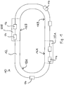
- Transport device 10 shown serves for the transport of objects not shown and comprises a rail 12 which defines a closed transport path along which the objects - eg workpieces - are transported. It is understood that the transport path could also be open and / or another, z. B. could have more complex course. The transport path can also form a circle, so that ultimately - seen functionally - a rotary indexing table is realized in which objects can be moved independently of each other.
- a plurality of carriages 14 are slidably or rollably guided on the rail 12.
- the objects to be transported are arranged on not shown transport platforms of the carriage 14 and are moved along with these along the transport path.
- the transport path is subdivided into two process sections 16A, 16B provided for processing the objects, indicated by dashed lines, and two respective transfer sections 18A, 18B lying therebetween.
- the transport path can have any desired number of process sections 16A, 16B and transfer sections 18A, 18B.
- the drive of the carriage 14 is based on a combination of two fundamentally different drive systems.
- the carriages 14 are driven by means of a linear motor arrangement, which, arranged in a basically known manner along the rail 12, comprises stationary stator elements and respective rotor elements arranged on the carriages 14.
- the carriages 14 can be moved between the process sections 16A, 16B at high speed by means of the linear motor arrangement.
- an electronic control unit is provided, which in Fig. 1 not shown.
- the carriages 14 are not driven by means of a linear motor arrangement, but by means of respective drive units 20A, 20B, which have cam drums which can be driven to rotate, as described below with reference to FIG Fig. 2 to 5 will be explained in more detail.
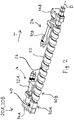
- Each of the two drive units 20A, 20B comprises a cam drum 22, which can be driven by means of a motor arrangement 24 to rotate about an axis of rotation D.
- the cam drum 22 includes a drive groove 26.
- the drive units 20A, 20B are each adjacent to the rail 12 (FIG. Fig. 1 ) arranged, provided on the carriage 14, not shown driver engage in the drive groove 26 when the corresponding carriage 14 enters the associated process section 16A, 16B. Due to the interaction of the drive groove 26 and the driver of the respective carriage 14 is moved in the direction of a direction parallel to the axis of rotation D extending transport direction T.
- Such a drive of a movable carriage 14 by means of a - as needed - to a uniform or to a time varying rotational movement driven cam drum 22 is basically known and allows a high positioning accuracy, which is suitable for processing the arranged on the carriage 14 objects in the process sections 16A 16B is significant.
- the cam drum 22 is divided into two separate coaxial drum sections 30A, 30B.
- the drive groove 26 is designed substantially helically in the region of the drum portion 30B. In principle, however, it may have one or more detents and / or sections with different gradients.
- the drum sections 30A, 30B are independently drivable by respective single motor units 32A, 32B of the motor assembly 24 and associated gear units 34A, 34B.
- first drum section 30A forward relative to the transport direction T is substantially shorter than the second drum section 30B.
- the first drum section 30A can therefore be rotatably mounted on a shaft of the second drum section 30B, which thereby functions as the overall shaft of the cam drum 22.
- the drive groove 26 - as already explained - in the present example in the region of the second drum portion 30B has a constant slope
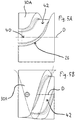
- the first drum section 30A it comprises a straight section 40 extending parallel to the transporting direction T and parallel to the axis of rotation D of the cam drum 22 and an adjoining helically extending section 42.
- the helically extending section 42 has a slope corresponding to that of FIG Incident of the drive groove 26 corresponds to the input portion of the second drum portion 30B, and it extends over a rotational angle, which is here between 90 ° and 180 °.
- sensors are provided to detect the rotational speeds and the instantaneous rotational positions of the drum sections 30A, 30B.
- the sensors are in signal connection with a control device.
- the control units associated with the drive units 20A, 20B and the control unit of the linear motor arrangement form a common control.
- carriages 14 with objects arranged thereon are taken over in succession by the drive units 20A, 20B from the transfer section 18A, 18B preceding with respect to the transport direction T.
- the controller causes the second drum portion 30B to be rotationally driven at a rotational speed adapted to that in the corresponding process portion 16A, 16B to produce a desired motion profile of the carriages 14 in that range.
- the first drum portion 30A is stationary, wherein the straight portion 40 of the drive groove 26 as in Fig. 2 and 3 shown pointing upwards.
- a driver provided on the underside of an arriving carriage 14 can therefore engage in the section 40 of the drive groove 26 without jerkiness and out of the movement brought about by the linear motor arrangement of the transfer section 18A, 18B.
- the first drum section 30A becomes driven to a rotary motion.
- the rotational movement is accelerated until the rotational speed of the first barrel portion 30A corresponds to the rotational speed of the second barrel portion 30B, and an exit portion of the portion 42 and an entrance portion of the drive groove 26 provided on the barrel portion 30B merge.
- section 30A is accelerated until synchronization of sections 30A, 30B has been achieved.
- the driver of the thus accelerated carriage 14 then passes smoothly into the second drum section 30B and is transported therefrom along the transport direction T. It will be understood that the second drum portion 30B, depending on its length as well as the dimensions of the carriages 14, can transport a plurality of carriages 14 at a time, if desired.
- the control device ensures that the first drum section 30A returns to the position shown in FIG Fig. 2 and 3 shown receiving rotary position is moved.
Landscapes
- Engineering & Computer Science (AREA)
- Mechanical Engineering (AREA)
- Chemical & Material Sciences (AREA)
- Combustion & Propulsion (AREA)
- Transportation (AREA)
- Transmission Devices (AREA)
Priority Applications (1)
| Application Number | Priority Date | Filing Date | Title |
|---|---|---|---|
| PL15726108T PL3137397T3 (pl) | 2014-05-30 | 2015-05-28 | Jednostka napędowa |
Applications Claiming Priority (2)
| Application Number | Priority Date | Filing Date | Title |
|---|---|---|---|
| DE102014107654.0A DE102014107654A1 (de) | 2014-05-30 | 2014-05-30 | Antriebseinheit |
| PCT/EP2015/061806 WO2015181277A1 (de) | 2014-05-30 | 2015-05-28 | Antriebseinheit |
Publications (2)
| Publication Number | Publication Date |
|---|---|
| EP3137397A1 EP3137397A1 (de) | 2017-03-08 |
| EP3137397B1 true EP3137397B1 (de) | 2019-09-25 |
Family
ID=53276116
Family Applications (1)
| Application Number | Title | Priority Date | Filing Date |
|---|---|---|---|
| EP15726108.2A Active EP3137397B1 (de) | 2014-05-30 | 2015-05-28 | Antriebseinheit |
Country Status (8)
| Country | Link |
|---|---|
| US (1) | US9862548B2 (pl) |
| EP (1) | EP3137397B1 (pl) |
| CN (1) | CN106488877B (pl) |
| CA (1) | CA2950226A1 (pl) |
| DE (1) | DE102014107654A1 (pl) |
| DK (1) | DK3137397T3 (pl) |
| PL (1) | PL3137397T3 (pl) |
| WO (1) | WO2015181277A1 (pl) |
Families Citing this family (10)
| Publication number | Priority date | Publication date | Assignee | Title |
|---|---|---|---|---|
| DE102015006098A1 (de) * | 2015-05-09 | 2016-11-10 | Eisenmann Se | Temperiervorrichtung zum Temperieren von Werkstücken |
| EP3522817B1 (en) | 2016-10-05 | 2021-12-08 | 3M Innovative Properties Company | Application device with redox initiator system, method of production and use thereof |
| DE102017116414A1 (de) * | 2017-07-20 | 2019-01-24 | Weiss Gmbh | Transportvorrichtung zur rotatorischen und/oder linearen bewegung eines werkstücks |
| DE102018007909B4 (de) | 2018-08-08 | 2020-06-25 | Global Systems Solutions GmbH | Transportsystem zum Transportieren und/oder Positionieren von Objekten entlang einer Transportstrecke sowie Transportkörper für ein solches Transportsystem |
| CN109230313A (zh) * | 2018-08-29 | 2019-01-18 | 博众精工科技股份有限公司 | 精定位传输线体 |
| CN109230314A (zh) * | 2018-08-29 | 2019-01-18 | 博众精工科技股份有限公司 | 柔性传输线体 |
| CN110052883B (zh) * | 2019-04-08 | 2021-04-06 | 科德数控股份有限公司 | 一种伺服凸轮工作台交换站送进装置 |
| CN113997910B (zh) * | 2020-07-28 | 2023-03-14 | 比亚迪股份有限公司 | 刹车控制系统和具有其的车辆 |
| KR102469777B1 (ko) * | 2021-09-30 | 2022-11-23 | 주식회사 지에스아이 | 하이브리드 lms 시스템 |
| CN117645100A (zh) * | 2023-11-22 | 2024-03-05 | 东莞市大成智能装备有限公司 | 一种复合传输装置以及电池干燥设备 |
Citations (2)
| Publication number | Priority date | Publication date | Assignee | Title |
|---|---|---|---|---|
| DE8913408U1 (de) * | 1989-10-25 | 1989-12-28 | Weiß, Dieter, 74722 Buchen | Palettenwechsler für einen linearen Horizontalförderer |
| US20140069780A1 (en) * | 2011-08-01 | 2014-03-13 | Toshiyuki Iba | Device for delivering conveying truck into screw driving area |
Family Cites Families (18)
| Publication number | Priority date | Publication date | Assignee | Title |
|---|---|---|---|---|
| FR2156497A1 (pl) * | 1971-10-22 | 1973-06-01 | Automatisme Tech | |
| FI792760A7 (fi) | 1978-09-11 | 1981-01-01 | Ab Knight Konsulterande Ingenjoerer | Kuljetusjärjestelmä. |
| DE2845978A1 (de) * | 1978-10-21 | 1980-04-30 | Bosch Gmbh Robert | Laengstransfer-montagemaschine |
| DE2845976C2 (de) | 1978-10-21 | 1985-05-23 | Daimler-Benz Ag, 7000 Stuttgart | Neigungsverstellbare Kopfstütze für Fahrzeugsitze |
| DE3131165C1 (de) * | 1981-08-06 | 1983-03-10 | Jagenberg-Werke AG, 4000 Düsseldorf | Förderschnecke für Gegenstände wie Flaschen etc. |
| DE3209595A1 (de) * | 1982-03-17 | 1983-10-06 | Benz & Hilgers Gmbh | Maschine zum abfuellen und verpacken von nahrungsmitteln |
| EP0127584A1 (de) * | 1983-05-31 | 1984-12-05 | Cantec, Inc. | Förderschneckentransport zum Transportieren von sich folgenden Werkstücken zu einer Bearbeitungsmaschine mit auf einer Bahn umlaufenden Werkzeugen |
| ATE64903T1 (de) * | 1983-12-13 | 1991-07-15 | Robert Andrew Hoehn | Schrittfoerderer fuer automatische produktionsverfahren. |
| CH668573A5 (de) * | 1984-08-08 | 1989-01-13 | Scharmann Gmbh & Co | Bearbeitungszentrum fuer werkstuecke. |
| DE3643329C2 (de) * | 1986-12-18 | 1996-02-22 | Ravensburg Maschf | Palettenwechselsystem |
| IT1238246B (it) * | 1990-02-14 | 1993-07-12 | Maurizio Marchesini | Dispositivo per l'alimentazione di flaconi a una macchina confezionatrice. |
| AT402629B (de) * | 1994-03-23 | 1997-07-25 | Doppelmayr & Sohn | Anlage zum transport von personen und/oder von anlage zum transport von personen und/oder von gütern gütern |
| US5881649A (en) * | 1996-08-13 | 1999-03-16 | Anelva Corporation | Magnetic transfer system, power transmission mechanism of the magnetic transfer system, and rotational driving member used for the system |
| JP3894461B2 (ja) * | 1997-01-17 | 2007-03-22 | キヤノンアネルバ株式会社 | 非接触式磁気搬送装置の位置決め制御装置および位置決め制御方法 |
| DE29908094U1 (de) * | 1999-05-06 | 2000-10-05 | Cooper Power Tools GmbH & Co., 73463 Westhausen | Transportsystem |
| JP5378167B2 (ja) * | 2009-11-16 | 2013-12-25 | トヨタ自動車東日本株式会社 | 搬送装置 |
| JP5459509B2 (ja) * | 2010-10-29 | 2014-04-02 | 株式会社ダイフク | 台車推進用スクリュー |
| DE102011113000A1 (de) | 2011-09-09 | 2013-03-14 | Weiss Gmbh | Transportvorrichtung |
-
2014
- 2014-05-30 DE DE102014107654.0A patent/DE102014107654A1/de not_active Withdrawn
-
2015
- 2015-05-28 CN CN201580028590.1A patent/CN106488877B/zh not_active Expired - Fee Related
- 2015-05-28 CA CA2950226A patent/CA2950226A1/en not_active Abandoned
- 2015-05-28 WO PCT/EP2015/061806 patent/WO2015181277A1/de not_active Ceased
- 2015-05-28 EP EP15726108.2A patent/EP3137397B1/de active Active
- 2015-05-28 DK DK15726108T patent/DK3137397T3/da active
- 2015-05-28 US US15/313,180 patent/US9862548B2/en not_active Expired - Fee Related
- 2015-05-28 PL PL15726108T patent/PL3137397T3/pl unknown
Patent Citations (2)
| Publication number | Priority date | Publication date | Assignee | Title |
|---|---|---|---|---|
| DE8913408U1 (de) * | 1989-10-25 | 1989-12-28 | Weiß, Dieter, 74722 Buchen | Palettenwechsler für einen linearen Horizontalförderer |
| US20140069780A1 (en) * | 2011-08-01 | 2014-03-13 | Toshiyuki Iba | Device for delivering conveying truck into screw driving area |
Also Published As
| Publication number | Publication date |
|---|---|
| EP3137397A1 (de) | 2017-03-08 |
| WO2015181277A1 (de) | 2015-12-03 |
| CN106488877A (zh) | 2017-03-08 |
| DK3137397T3 (da) | 2019-12-02 |
| PL3137397T3 (pl) | 2020-06-15 |
| US9862548B2 (en) | 2018-01-09 |
| DE102014107654A1 (de) | 2015-12-03 |
| US20170190514A1 (en) | 2017-07-06 |
| CA2950226A1 (en) | 2015-12-03 |
| CN106488877B (zh) | 2019-05-14 |
Similar Documents
| Publication | Publication Date | Title |
|---|---|---|
| EP3137397B1 (de) | Antriebseinheit | |
| EP2511203B1 (de) | Verfahren und Vorrichtung zum Transportieren von Behältnissen oder Behältnisgebinden | |
| EP3053443B1 (de) | Wurstgruppierer und Verfahren zum Gruppieren von Würsten zu Wurstgruppen | |
| EP2418161B1 (de) | System und Verfahren zum Fördern und Umlenken eines Lastträgers | |
| EP3057891B1 (de) | Ausleitvorrichtung zum ausleiten von behältern | |
| EP3602217B1 (de) | Transportvorrichtung zur rotatorischen und/oder linearen bewegung eines werkstücks | |
| EP4335296A2 (de) | Anordnung und verfahren zur geflügelförderung | |
| EP3016760B1 (de) | Vorrichtung und verfahren zum transferieren eines bauteils und werkzeugsystem | |
| EP2478782B1 (de) | Fördervorrichtung für stabförmige produkte der tabak verarbeitenden industrie | |
| EP1256415B1 (de) | Vorrichtung zur Rückführung von Werkstücken | |
| EP3455434B1 (de) | Vorrichtung und verfahren zum parken eines fahrzeuges | |
| DE102018007909B4 (de) | Transportsystem zum Transportieren und/oder Positionieren von Objekten entlang einer Transportstrecke sowie Transportkörper für ein solches Transportsystem | |
| EP2726222B1 (de) | Vorrichtung zum ausscheiden von ausschussgütern | |
| EP3904250B1 (de) | Vorrichtung und verfahren zum zuführen von flächenförmigen gütern zu einer bearbeitungseinheit | |
| EP3023368A1 (de) | Puffertisch für behälter | |
| EP3802383B1 (de) | Weichenvorrichtung | |
| EP2030725B1 (de) | Vorrichtung und Verfahren zum Ausrichten von Werkstücken | |
| EP4065496B1 (de) | Vorrichtung zum wenden länglicher gegenstände | |
| EP4427595B1 (de) | Teigverarbeitungsanlage mit produktprogrammweiterleitung | |
| DE19613901A1 (de) | Teleskop-Handhabungseinrichtung | |
| EP4230552A1 (de) | Vereinzelungsvorrichtung für hängeförderanlage | |
| DE9411706U1 (de) | Einrichtung zur Handhabung eines Werkstückträgers in einer Bearbeitungsstation | |
| DE10020607A1 (de) | Übergabevorrichtung in einer Verpackungsmaschine | |
| DE102014226780A1 (de) | Vorrichtung und Verfahren für eine getaktete Durchlaufanlage | |
| DE4331755A1 (de) | Vorrichtung zum Drehen von Flaschenkästen o. dgl. Gebinde |
Legal Events
| Date | Code | Title | Description |
|---|---|---|---|
| STAA | Information on the status of an ep patent application or granted ep patent |
Free format text: STATUS: THE INTERNATIONAL PUBLICATION HAS BEEN MADE |
|
| PUAI | Public reference made under article 153(3) epc to a published international application that has entered the european phase |
Free format text: ORIGINAL CODE: 0009012 |
|
| STAA | Information on the status of an ep patent application or granted ep patent |
Free format text: STATUS: REQUEST FOR EXAMINATION WAS MADE |
|
| 17P | Request for examination filed |
Effective date: 20161128 |
|
| AK | Designated contracting states |
Kind code of ref document: A1 Designated state(s): AL AT BE BG CH CY CZ DE DK EE ES FI FR GB GR HR HU IE IS IT LI LT LU LV MC MK MT NL NO PL PT RO RS SE SI SK SM TR |
|
| AX | Request for extension of the european patent |
Extension state: BA ME |
|
| DAV | Request for validation of the european patent (deleted) | ||
| DAX | Request for extension of the european patent (deleted) | ||
| STAA | Information on the status of an ep patent application or granted ep patent |
Free format text: STATUS: EXAMINATION IS IN PROGRESS |
|
| 17Q | First examination report despatched |
Effective date: 20180613 |
|
| GRAP | Despatch of communication of intention to grant a patent |
Free format text: ORIGINAL CODE: EPIDOSNIGR1 |
|
| STAA | Information on the status of an ep patent application or granted ep patent |
Free format text: STATUS: GRANT OF PATENT IS INTENDED |
|
| INTG | Intention to grant announced |
Effective date: 20190405 |
|
| GRAS | Grant fee paid |
Free format text: ORIGINAL CODE: EPIDOSNIGR3 |
|
| GRAA | (expected) grant |
Free format text: ORIGINAL CODE: 0009210 |
|
| STAA | Information on the status of an ep patent application or granted ep patent |
Free format text: STATUS: THE PATENT HAS BEEN GRANTED |
|
| AK | Designated contracting states |
Kind code of ref document: B1 Designated state(s): AL AT BE BG CH CY CZ DE DK EE ES FI FR GB GR HR HU IE IS IT LI LT LU LV MC MK MT NL NO PL PT RO RS SE SI SK SM TR |
|
| REG | Reference to a national code |
Ref country code: GB Ref legal event code: FG4D Free format text: NOT ENGLISH |
|
| REG | Reference to a national code |
Ref country code: CH Ref legal event code: EP |
|
| REG | Reference to a national code |
Ref country code: DE Ref legal event code: R096 Ref document number: 502015010465 Country of ref document: DE |
|
| REG | Reference to a national code |
Ref country code: AT Ref legal event code: REF Ref document number: 1183631 Country of ref document: AT Kind code of ref document: T Effective date: 20191015 |
|
| REG | Reference to a national code |
Ref country code: IE Ref legal event code: FG4D Free format text: LANGUAGE OF EP DOCUMENT: GERMAN |
|
| REG | Reference to a national code |
Ref country code: DK Ref legal event code: T3 Effective date: 20191128 |
|
| REG | Reference to a national code |
Ref country code: CH Ref legal event code: NV Representative=s name: DR. GRAF AND PARTNER AG INTELLECTUAL PROPERTY, CH |
|
| REG | Reference to a national code |
Ref country code: NL Ref legal event code: FP |
|
| PG25 | Lapsed in a contracting state [announced via postgrant information from national office to epo] |
Ref country code: SE Free format text: LAPSE BECAUSE OF FAILURE TO SUBMIT A TRANSLATION OF THE DESCRIPTION OR TO PAY THE FEE WITHIN THE PRESCRIBED TIME-LIMIT Effective date: 20190925 Ref country code: BG Free format text: LAPSE BECAUSE OF FAILURE TO SUBMIT A TRANSLATION OF THE DESCRIPTION OR TO PAY THE FEE WITHIN THE PRESCRIBED TIME-LIMIT Effective date: 20191225 Ref country code: LT Free format text: LAPSE BECAUSE OF FAILURE TO SUBMIT A TRANSLATION OF THE DESCRIPTION OR TO PAY THE FEE WITHIN THE PRESCRIBED TIME-LIMIT Effective date: 20190925 Ref country code: HR Free format text: LAPSE BECAUSE OF FAILURE TO SUBMIT A TRANSLATION OF THE DESCRIPTION OR TO PAY THE FEE WITHIN THE PRESCRIBED TIME-LIMIT Effective date: 20190925 Ref country code: NO Free format text: LAPSE BECAUSE OF FAILURE TO SUBMIT A TRANSLATION OF THE DESCRIPTION OR TO PAY THE FEE WITHIN THE PRESCRIBED TIME-LIMIT Effective date: 20191225 |
|
| REG | Reference to a national code |
Ref country code: LT Ref legal event code: MG4D |
|
| PG25 | Lapsed in a contracting state [announced via postgrant information from national office to epo] |
Ref country code: GR Free format text: LAPSE BECAUSE OF FAILURE TO SUBMIT A TRANSLATION OF THE DESCRIPTION OR TO PAY THE FEE WITHIN THE PRESCRIBED TIME-LIMIT Effective date: 20191226 Ref country code: LV Free format text: LAPSE BECAUSE OF FAILURE TO SUBMIT A TRANSLATION OF THE DESCRIPTION OR TO PAY THE FEE WITHIN THE PRESCRIBED TIME-LIMIT Effective date: 20190925 Ref country code: RS Free format text: LAPSE BECAUSE OF FAILURE TO SUBMIT A TRANSLATION OF THE DESCRIPTION OR TO PAY THE FEE WITHIN THE PRESCRIBED TIME-LIMIT Effective date: 20190925 |
|
| PG25 | Lapsed in a contracting state [announced via postgrant information from national office to epo] |
Ref country code: AL Free format text: LAPSE BECAUSE OF FAILURE TO SUBMIT A TRANSLATION OF THE DESCRIPTION OR TO PAY THE FEE WITHIN THE PRESCRIBED TIME-LIMIT Effective date: 20190925 Ref country code: ES Free format text: LAPSE BECAUSE OF FAILURE TO SUBMIT A TRANSLATION OF THE DESCRIPTION OR TO PAY THE FEE WITHIN THE PRESCRIBED TIME-LIMIT Effective date: 20190925 Ref country code: PT Free format text: LAPSE BECAUSE OF FAILURE TO SUBMIT A TRANSLATION OF THE DESCRIPTION OR TO PAY THE FEE WITHIN THE PRESCRIBED TIME-LIMIT Effective date: 20200127 Ref country code: RO Free format text: LAPSE BECAUSE OF FAILURE TO SUBMIT A TRANSLATION OF THE DESCRIPTION OR TO PAY THE FEE WITHIN THE PRESCRIBED TIME-LIMIT Effective date: 20190925 Ref country code: EE Free format text: LAPSE BECAUSE OF FAILURE TO SUBMIT A TRANSLATION OF THE DESCRIPTION OR TO PAY THE FEE WITHIN THE PRESCRIBED TIME-LIMIT Effective date: 20190925 |
|
| PG25 | Lapsed in a contracting state [announced via postgrant information from national office to epo] |
Ref country code: SM Free format text: LAPSE BECAUSE OF FAILURE TO SUBMIT A TRANSLATION OF THE DESCRIPTION OR TO PAY THE FEE WITHIN THE PRESCRIBED TIME-LIMIT Effective date: 20190925 Ref country code: IS Free format text: LAPSE BECAUSE OF FAILURE TO SUBMIT A TRANSLATION OF THE DESCRIPTION OR TO PAY THE FEE WITHIN THE PRESCRIBED TIME-LIMIT Effective date: 20200224 Ref country code: SK Free format text: LAPSE BECAUSE OF FAILURE TO SUBMIT A TRANSLATION OF THE DESCRIPTION OR TO PAY THE FEE WITHIN THE PRESCRIBED TIME-LIMIT Effective date: 20190925 Ref country code: CZ Free format text: LAPSE BECAUSE OF FAILURE TO SUBMIT A TRANSLATION OF THE DESCRIPTION OR TO PAY THE FEE WITHIN THE PRESCRIBED TIME-LIMIT Effective date: 20190925 |
|
| REG | Reference to a national code |
Ref country code: DE Ref legal event code: R097 Ref document number: 502015010465 Country of ref document: DE |
|
| PG2D | Information on lapse in contracting state deleted |
Ref country code: IS |
|
| PG25 | Lapsed in a contracting state [announced via postgrant information from national office to epo] |
Ref country code: IS Free format text: LAPSE BECAUSE OF FAILURE TO SUBMIT A TRANSLATION OF THE DESCRIPTION OR TO PAY THE FEE WITHIN THE PRESCRIBED TIME-LIMIT Effective date: 20200126 |
|
| PLBE | No opposition filed within time limit |
Free format text: ORIGINAL CODE: 0009261 |
|
| STAA | Information on the status of an ep patent application or granted ep patent |
Free format text: STATUS: NO OPPOSITION FILED WITHIN TIME LIMIT |
|
| 26N | No opposition filed |
Effective date: 20200626 |
|
| PG25 | Lapsed in a contracting state [announced via postgrant information from national office to epo] |
Ref country code: SI Free format text: LAPSE BECAUSE OF FAILURE TO SUBMIT A TRANSLATION OF THE DESCRIPTION OR TO PAY THE FEE WITHIN THE PRESCRIBED TIME-LIMIT Effective date: 20190925 |
|
| REG | Reference to a national code |
Ref country code: DE Ref legal event code: R119 Ref document number: 502015010465 Country of ref document: DE |
|
| REG | Reference to a national code |
Ref country code: FI Ref legal event code: MAE |
|
| REG | Reference to a national code |
Ref country code: DK Ref legal event code: EBP Effective date: 20200531 |
|
| REG | Reference to a national code |
Ref country code: NL Ref legal event code: MM Effective date: 20200601 |
|
| PG25 | Lapsed in a contracting state [announced via postgrant information from national office to epo] |
Ref country code: MC Free format text: LAPSE BECAUSE OF FAILURE TO SUBMIT A TRANSLATION OF THE DESCRIPTION OR TO PAY THE FEE WITHIN THE PRESCRIBED TIME-LIMIT Effective date: 20190925 Ref country code: FI Free format text: LAPSE BECAUSE OF NON-PAYMENT OF DUE FEES Effective date: 20200528 Ref country code: LI Free format text: LAPSE BECAUSE OF NON-PAYMENT OF DUE FEES Effective date: 20200531 Ref country code: CH Free format text: LAPSE BECAUSE OF NON-PAYMENT OF DUE FEES Effective date: 20200531 |
|
| PG25 | Lapsed in a contracting state [announced via postgrant information from national office to epo] |
Ref country code: NL Free format text: LAPSE BECAUSE OF NON-PAYMENT OF DUE FEES Effective date: 20200601 |
|
| REG | Reference to a national code |
Ref country code: BE Ref legal event code: MM Effective date: 20200531 |
|
| GBPC | Gb: european patent ceased through non-payment of renewal fee |
Effective date: 20200528 |
|
| PG25 | Lapsed in a contracting state [announced via postgrant information from national office to epo] |
Ref country code: LU Free format text: LAPSE BECAUSE OF NON-PAYMENT OF DUE FEES Effective date: 20200528 |
|
| PG25 | Lapsed in a contracting state [announced via postgrant information from national office to epo] |
Ref country code: IE Free format text: LAPSE BECAUSE OF NON-PAYMENT OF DUE FEES Effective date: 20200528 Ref country code: GB Free format text: LAPSE BECAUSE OF NON-PAYMENT OF DUE FEES Effective date: 20200528 Ref country code: DK Free format text: LAPSE BECAUSE OF NON-PAYMENT OF DUE FEES Effective date: 20200531 Ref country code: FR Free format text: LAPSE BECAUSE OF NON-PAYMENT OF DUE FEES Effective date: 20200531 |
|
| PG25 | Lapsed in a contracting state [announced via postgrant information from national office to epo] |
Ref country code: BE Free format text: LAPSE BECAUSE OF NON-PAYMENT OF DUE FEES Effective date: 20200531 Ref country code: DE Free format text: LAPSE BECAUSE OF NON-PAYMENT OF DUE FEES Effective date: 20201201 |
|
| REG | Reference to a national code |
Ref country code: AT Ref legal event code: MM01 Ref document number: 1183631 Country of ref document: AT Kind code of ref document: T Effective date: 20200528 |
|
| PG25 | Lapsed in a contracting state [announced via postgrant information from national office to epo] |
Ref country code: AT Free format text: LAPSE BECAUSE OF NON-PAYMENT OF DUE FEES Effective date: 20200528 |
|
| PG25 | Lapsed in a contracting state [announced via postgrant information from national office to epo] |
Ref country code: IT Free format text: LAPSE BECAUSE OF NON-PAYMENT OF DUE FEES Effective date: 20200528 |
|
| PG25 | Lapsed in a contracting state [announced via postgrant information from national office to epo] |
Ref country code: TR Free format text: LAPSE BECAUSE OF FAILURE TO SUBMIT A TRANSLATION OF THE DESCRIPTION OR TO PAY THE FEE WITHIN THE PRESCRIBED TIME-LIMIT Effective date: 20190925 Ref country code: MT Free format text: LAPSE BECAUSE OF FAILURE TO SUBMIT A TRANSLATION OF THE DESCRIPTION OR TO PAY THE FEE WITHIN THE PRESCRIBED TIME-LIMIT Effective date: 20190925 Ref country code: CY Free format text: LAPSE BECAUSE OF FAILURE TO SUBMIT A TRANSLATION OF THE DESCRIPTION OR TO PAY THE FEE WITHIN THE PRESCRIBED TIME-LIMIT Effective date: 20190925 |
|
| PG25 | Lapsed in a contracting state [announced via postgrant information from national office to epo] |
Ref country code: MK Free format text: LAPSE BECAUSE OF FAILURE TO SUBMIT A TRANSLATION OF THE DESCRIPTION OR TO PAY THE FEE WITHIN THE PRESCRIBED TIME-LIMIT Effective date: 20190925 |
|
| PG25 | Lapsed in a contracting state [announced via postgrant information from national office to epo] |
Ref country code: PL Free format text: LAPSE BECAUSE OF NON-PAYMENT OF DUE FEES Effective date: 20200528 |