EP3136451A1 - Solarzelle mit kristallinem silicium, solarzellenmodul mit kristallinem silicium und herstellungsverfahren dafür - Google Patents
Solarzelle mit kristallinem silicium, solarzellenmodul mit kristallinem silicium und herstellungsverfahren dafür Download PDFInfo
- Publication number
- EP3136451A1 EP3136451A1 EP15785959.6A EP15785959A EP3136451A1 EP 3136451 A1 EP3136451 A1 EP 3136451A1 EP 15785959 A EP15785959 A EP 15785959A EP 3136451 A1 EP3136451 A1 EP 3136451A1
- Authority
- EP
- European Patent Office
- Prior art keywords
- film
- based thin
- silicon
- transparent electrode
- electrode layer
- Prior art date
- Legal status (The legal status is an assumption and is not a legal conclusion. Google has not performed a legal analysis and makes no representation as to the accuracy of the status listed.)
- Granted
Links
Images

Classifications
-
- H—ELECTRICITY
- H10—SEMICONDUCTOR DEVICES; ELECTRIC SOLID-STATE DEVICES NOT OTHERWISE PROVIDED FOR
- H10F—INORGANIC SEMICONDUCTOR DEVICES SENSITIVE TO INFRARED RADIATION, LIGHT, ELECTROMAGNETIC RADIATION OF SHORTER WAVELENGTH OR CORPUSCULAR RADIATION
- H10F10/00—Individual photovoltaic cells, e.g. solar cells
- H10F10/10—Individual photovoltaic cells, e.g. solar cells having potential barriers
- H10F10/16—Photovoltaic cells having only PN heterojunction potential barriers
- H10F10/164—Photovoltaic cells having only PN heterojunction potential barriers comprising heterojunctions with Group IV materials, e.g. ITO/Si or GaAs/SiGe photovoltaic cells
- H10F10/165—Photovoltaic cells having only PN heterojunction potential barriers comprising heterojunctions with Group IV materials, e.g. ITO/Si or GaAs/SiGe photovoltaic cells the heterojunctions being Group IV-IV heterojunctions, e.g. Si/Ge, SiGe/Si or Si/SiC photovoltaic cells
- H10F10/166—Photovoltaic cells having only PN heterojunction potential barriers comprising heterojunctions with Group IV materials, e.g. ITO/Si or GaAs/SiGe photovoltaic cells the heterojunctions being Group IV-IV heterojunctions, e.g. Si/Ge, SiGe/Si or Si/SiC photovoltaic cells the Group IV-IV heterojunctions being heterojunctions of crystalline and amorphous materials, e.g. silicon heterojunction [SHJ] photovoltaic cells
-
- H—ELECTRICITY
- H10—SEMICONDUCTOR DEVICES; ELECTRIC SOLID-STATE DEVICES NOT OTHERWISE PROVIDED FOR
- H10F—INORGANIC SEMICONDUCTOR DEVICES SENSITIVE TO INFRARED RADIATION, LIGHT, ELECTROMAGNETIC RADIATION OF SHORTER WAVELENGTH OR CORPUSCULAR RADIATION
- H10F19/00—Integrated devices, or assemblies of multiple devices, comprising at least one photovoltaic cell covered by group H10F10/00, e.g. photovoltaic modules
- H10F19/90—Structures for connecting between photovoltaic cells, e.g. interconnections or insulating spacers
- H10F19/902—Structures for connecting between photovoltaic cells, e.g. interconnections or insulating spacers for series or parallel connection of photovoltaic cells
-
- H—ELECTRICITY
- H10—SEMICONDUCTOR DEVICES; ELECTRIC SOLID-STATE DEVICES NOT OTHERWISE PROVIDED FOR
- H10F—INORGANIC SEMICONDUCTOR DEVICES SENSITIVE TO INFRARED RADIATION, LIGHT, ELECTROMAGNETIC RADIATION OF SHORTER WAVELENGTH OR CORPUSCULAR RADIATION
- H10F71/00—Manufacture or treatment of devices covered by this subclass
- H10F71/121—The active layers comprising only Group IV materials
-
- H—ELECTRICITY
- H10—SEMICONDUCTOR DEVICES; ELECTRIC SOLID-STATE DEVICES NOT OTHERWISE PROVIDED FOR
- H10F—INORGANIC SEMICONDUCTOR DEVICES SENSITIVE TO INFRARED RADIATION, LIGHT, ELECTROMAGNETIC RADIATION OF SHORTER WAVELENGTH OR CORPUSCULAR RADIATION
- H10F71/00—Manufacture or treatment of devices covered by this subclass
- H10F71/133—Providing edge isolation
-
- H—ELECTRICITY
- H10—SEMICONDUCTOR DEVICES; ELECTRIC SOLID-STATE DEVICES NOT OTHERWISE PROVIDED FOR
- H10F—INORGANIC SEMICONDUCTOR DEVICES SENSITIVE TO INFRARED RADIATION, LIGHT, ELECTROMAGNETIC RADIATION OF SHORTER WAVELENGTH OR CORPUSCULAR RADIATION
- H10F77/00—Constructional details of devices covered by this subclass
- H10F77/10—Semiconductor bodies
- H10F77/14—Shape of semiconductor bodies; Shapes, relative sizes or dispositions of semiconductor regions within semiconductor bodies
- H10F77/148—Shapes of potential barriers
-
- H—ELECTRICITY
- H10—SEMICONDUCTOR DEVICES; ELECTRIC SOLID-STATE DEVICES NOT OTHERWISE PROVIDED FOR
- H10F—INORGANIC SEMICONDUCTOR DEVICES SENSITIVE TO INFRARED RADIATION, LIGHT, ELECTROMAGNETIC RADIATION OF SHORTER WAVELENGTH OR CORPUSCULAR RADIATION
- H10F77/00—Constructional details of devices covered by this subclass
- H10F77/20—Electrodes
- H10F77/206—Electrodes for devices having potential barriers
- H10F77/211—Electrodes for devices having potential barriers for photovoltaic cells
-
- H—ELECTRICITY
- H10—SEMICONDUCTOR DEVICES; ELECTRIC SOLID-STATE DEVICES NOT OTHERWISE PROVIDED FOR
- H10F—INORGANIC SEMICONDUCTOR DEVICES SENSITIVE TO INFRARED RADIATION, LIGHT, ELECTROMAGNETIC RADIATION OF SHORTER WAVELENGTH OR CORPUSCULAR RADIATION
- H10F77/00—Constructional details of devices covered by this subclass
- H10F77/20—Electrodes
- H10F77/244—Electrodes made of transparent conductive layers, e.g. transparent conductive oxide [TCO] layers
-
- H—ELECTRICITY
- H10—SEMICONDUCTOR DEVICES; ELECTRIC SOLID-STATE DEVICES NOT OTHERWISE PROVIDED FOR
- H10F—INORGANIC SEMICONDUCTOR DEVICES SENSITIVE TO INFRARED RADIATION, LIGHT, ELECTROMAGNETIC RADIATION OF SHORTER WAVELENGTH OR CORPUSCULAR RADIATION
- H10F77/00—Constructional details of devices covered by this subclass
- H10F77/30—Coatings
- H10F77/306—Coatings for devices having potential barriers
- H10F77/311—Coatings for devices having potential barriers for photovoltaic cells
-
- Y—GENERAL TAGGING OF NEW TECHNOLOGICAL DEVELOPMENTS; GENERAL TAGGING OF CROSS-SECTIONAL TECHNOLOGIES SPANNING OVER SEVERAL SECTIONS OF THE IPC; TECHNICAL SUBJECTS COVERED BY FORMER USPC CROSS-REFERENCE ART COLLECTIONS [XRACs] AND DIGESTS
- Y02—TECHNOLOGIES OR APPLICATIONS FOR MITIGATION OR ADAPTATION AGAINST CLIMATE CHANGE
- Y02E—REDUCTION OF GREENHOUSE GAS [GHG] EMISSIONS, RELATED TO ENERGY GENERATION, TRANSMISSION OR DISTRIBUTION
- Y02E10/00—Energy generation through renewable energy sources
- Y02E10/50—Photovoltaic [PV] energy
- Y02E10/547—Monocrystalline silicon PV cells
-
- Y—GENERAL TAGGING OF NEW TECHNOLOGICAL DEVELOPMENTS; GENERAL TAGGING OF CROSS-SECTIONAL TECHNOLOGIES SPANNING OVER SEVERAL SECTIONS OF THE IPC; TECHNICAL SUBJECTS COVERED BY FORMER USPC CROSS-REFERENCE ART COLLECTIONS [XRACs] AND DIGESTS
- Y02—TECHNOLOGIES OR APPLICATIONS FOR MITIGATION OR ADAPTATION AGAINST CLIMATE CHANGE
- Y02P—CLIMATE CHANGE MITIGATION TECHNOLOGIES IN THE PRODUCTION OR PROCESSING OF GOODS
- Y02P70/00—Climate change mitigation technologies in the production process for final industrial or consumer products
- Y02P70/50—Manufacturing or production processes characterised by the final manufactured product
Definitions
- the invention relates to a crystalline silicon-based solar cell having a heterojunction on a crystalline silicon substrate surface, a crystalline silicon-based solar cell module, and manufacturing method therefor.
- a crystalline silicon-based solar cell including a conductive silicon-based thin-film on a single-crystalline silicon substrate is called a heterojunction solar cell.
- a heterojunction solar cell including an intrinsic amorphous silicon thin-film between a conductive silicon-based thin-film and a crystalline silicon substrate is known as one of forms of crystalline silicon-based solar cells having the highest conversion efficiency.
- a heterojunction solar cell includes silicon-based thin-film of opposite-conductivity-type on the light-receiving side of a crystalline silicon substrate of first conductivity-type, and silicon-based thin-film of first conductivity-type on the back side of the crystalline silicon substrate of first conductivity-type.
- an n-type single-crystalline silicon substrate is used, and a p-type silicon-based thin-film is formed on the light-receiving side thereof, while an n-type silicon-based thin-film is formed on the back side thereof.
- Carriers generated at these semiconductor junction portions are extracted outside of a solar cell via an electrode.
- the electrode a combination of a transparent electroconductive layer and a metal collecting electrode is generally used.
- a line-shape patterned metal collecting electrode is used on the light-receiving side for enlarging the light-receiving area of the solar cell.
- Patent Document 1 discloses a heterojunction solar cell in which a patterned collecting electrode is formed on the light-receiving side of the solar cell by a plating method, and a silver electrode is formed on the entire surface on the back side of the solar cell by a sputtering method.
- Patent Document 2 discloses a heterojunction solar cell in which a metal electrode is formed on the entire surface on the back side by electroplating. In electroplating, a metal electrode having a large thickness can be easily formed, and therefore improvement of characteristics and productivity by reduction of the resistance of the metal electrode can be expected.
- Patent Document 1 it is known that in production of a heterojunction solar cell, a silicon-based thin-film and a transparent electrode layer are also formed on the side surface of a silicon substrate and a surface opposite to a deposition surface by wraparound, so that a short-circuit between transparent electrodes on the front and the back generates.
- a metal electrode is formed on the back side by electroplating in a state in which the electrodes on front and back are short-circuited, a metal layer is also precipitated on the light-receiving side to generate a new leakage pass, a shading loss and so on.
- the present inventors have conducted studies, and found that when a metal electrode is formed on the back side of a heterojunction solar cell by a plating method, the problem that a metal component is diffused from a plating solution into a silicon substrate, or an undesired metal is precipitated due to leakage which is not associated with a short-circuit between transparent electrode layers on the front and the back cannot be solved merely by eliminating a short-circuit between transparent electrode layers on the front and the back.
- an object of the present invention is to improve the productivity and conversion efficiency of a solar cell by forming a back metal electrode using an electroplating method capable of reducing a process cost; and suppressing precipitation of an undesired metal, diffusion of a metal into a silicon substrate, and so on.
- a plated metal electrode is formed on the back side by electroplating in a state in which a specific insulating region is provided at the peripheral edge on the light-receiving side. According to this configuration, precipitation of an undesired metal due to leakage can be suppressed in electroplating.
- an n-type crystalline silicon substrate having a first principal surface, a second principal surface and a side surface is used.
- the crystalline silicon-based solar cell includes: an n-type crystalline silicon substrate; a first intrinsic silicon-based thin-film, a p-type silicon-based thin-film, a first transparent electrode layer and a patterned collecting electrode which are sequentially formed on a first principal surface of the n-type crystalline silicon substrate; and a second intrinsic silicon-based thin-film, an n-type silicon-based thin-film, a second transparent electrode layer and a plated metal electrode which are sequentially formed on a second principal surface of the n-type crystalline silicon substrate.
- the plated metal electrode is formed on the entire region of the second transparent electrode layer.
- the crystalline silicon-based solar cell according to the present invention has an insulating region is provided at the peripheral edge of the first principal surface, wherein the insulating region is freed of a short circuit between the first transparent electrode layer and the second transparent electrode layer.
- a method for manufacturing a crystalline silicon-based solar cell includes the steps of: depositing a first intrinsic silicon-based thin-film on the entire region of a first principal surface and the side surface of an n-type crystalline silicon substrate (first intrinsic silicon-based thin-film forming step); depositing a p-type silicon-based thin-film on the first intrinsic silicon-based thin-film (p-type silicon-based thin-film forming step); depositing a first transparent electrode layer on the entire region of the first principal surface except for the peripheral edge thereof (first transparent electrode layer forming step); depositing a second intrinsic silicon-based thin-film on the entire region of a second principal surface and the side surface of the n-type crystalline silicon substrate (second intrinsic silicon-based thin-film forming step); depositing an n-type silicon-based thin-film on the second intrinsic silicon-based thin-film (n-type silicon-based thin-film forming step); and depositing a second transparent electrode layer on the n-type silicon-based thin-film (second transparent electrode layer).
- a step of forming a plated metal electrode on the entire surface of the second transparent electrode layer by an electroplating method in a state in which the insulating region is provided at the peripheral edge of the first principal surface is carried out.
- the first transparent electrode layer forming step by performing deposition under a state in which the peripheral edge of the first principal surface is covered with a mask, the first transparent electrode layer is formed on the entire region of the first principal surface except for the peripheral edge thereof. Accordingly, the insulating region can be formed at the peripheral edge of the first principal surface.
- the second transparent electrode layer is also formed on the side surface as well as the entire second principal surface. For example, by performing deposition without using a mask in the second transparent electrode layer forming step, the second transparent electrode layer is formed on the entire surface of the second principal surface and the side surface.
- the p-type silicon-based thin-film is formed on the entire first principal surface and the side surface, and the n-type silicon-based thin-film is formed on the entire second principal surface and the side surface.
- it is preferable that deposition of the p-type silicon-based thin-film is performed before deposition of the n-type silicon-based thin-film.
- the p-type silicon-based thin-film is situated closer to the n-type crystalline silicon substrate than the n-type silicon-based thin-film. In this case, precipitation of an undesired metal due to leakage is further suppressed.
- an underlying metal layer may be formed on the entire surface of the second transparent electrode layer.
- a plated electrode layer is formed on the underlying metal layer by electroplating.
- the crystalline silicon-based solar cell according to the present invention includes a plated metal electrode on the entire surface on the back side, and therefore light that has been transmitted without being absorbed by the crystalline silicon substrate can be reflected by the metal electrode on the back side to improve light utilization efficiency.
- the plated metal electrode is formed by an electroplating method, and therefore the electrode having a large thickness can be easily formed. Further, electroplating is performed in a state in which a specific insulating region is provided, and therefore precipitation of an undesired metal, diffusion of a metal into the silicon substrate, and so on are suppressed.
- the productivity and conversion efficiency of the solar cell can be improved.
- FIG. 1 is a schematic sectional view of a crystalline silicon-based solar cell according to one embodiment of the present invention.
- An n-type single-crystalline silicon substrate is used in the crystalline silicon-based solar cell of the present invention.
- the crystalline silicon substrate 1 has first principal surface 51, second principal surface 52 and side surface 55.
- the crystalline silicon-based solar cell according to the present invention is so called a heterojunction solar cell, and includes a first intrinsic silicon-based thin-film 2, a p-type silicon-based thin-film 3, a first transparent electrode layer 4 and a patterned collecting electrode 11 on the first principal surface 51 of the n-type crystalline silicon substrate 1; and a second intrinsic silicon-based thin-film 7, an n-type silicon-based thin-film 8, a second transparent electrode layer 9 and a plated metal electrode 21 on the second principal surface 52 of the n-type crystalline silicon substrate 1.
- an n-type single-crystalline silicon substrate is used as the crystalline silicon substrate 1.
- a strong electric field can be provided to efficiently separate and collect electron-hole pairs when the heterojunction on the light-receiving side, at which light incident to the crystalline silicon substrate is absorbed in the largest amount, is a reverse junction.
- the first principal surface provided with the p-type silicon-based thin-film 3 is a light-receiving surface, conversion efficiency is improved.
- the single-crystalline silicon substrate 1 preferably has textured structure (not illustrated in the drawings) in its surface.
- a first intrinsic silicon-based thin-film 2 and a p-type silicon-based thin-film 3 are formed as silicon-based thin-films.
- a second intrinsic silicon-based thin-film 7 and an n-type silicon-based thin-film 8 are formed as silicon-based thin-films
- the intrinsic silicon-based thin-films 2 and 7 are preferably i-type hydrogenated amorphous silicon composed of silicon and hydrogen.
- i-type hydrogenated amorphous silicon is deposited on a crystalline silicon substrate, surface passivation can be effectively performed while suppressing diffusion of impurities to the crystalline silicon substrate.
- the conductive (p-type or n-type) silicon-based thin-films 3 and 8 may be amorphous silicon-based thin-films, microcrystalline silicon-based thin-films (thin-films containing amorphous silicon and crystalline silicon), and the like.
- silicon-based thin-film not only silicon but also a silicon-based alloy such as silicon oxide, silicon carbide or silicon nitride can be used.
- the conductive silicon-based thin-film is preferably an amorphous silicon thin-film.
- transparent electrode layers 4 and 9 are formed, respectively.
- conductive metal oxide such as zinc oxide, indium oxide and tin oxide, or composite metal oxides thereof is used. Among them, indium-based oxides are preferable from the viewpoints of electroconductivity, optical characteristics and long-term reliability, and one having indium tin oxide (ITO) as a main component is especially preferable.
- the transparent electrode layer may be a single layer or a layered structure composed of multiple layers.
- Each of the first transparent electrode layer 4 and the second transparent electrode layer 9 preferably has a thickness of 10 nm or more and 140 nm or less, from the viewpoints of transparency, electroconductivity and reduction of light reflection.
- the wording "as a main component” means that the content is more than 50% by weight, preferably 70% by weight or more, more preferably 90% by weight or more.
- the method for forming the silicon-based thin-films 2, 3, 7 and 8 and the transparent electrode layers 4 and 9 a dry process such as a CVD method, a sputtering method or a vapor deposition method is preferred.
- the silicon-based thin-films are formed preferably by a plasma-enhanced CVD method.
- the method for forming the transparent electrode layers is preferably a physical vapor deposition method such as a sputtering method, a CVD method using a reaction of an organic metal compound with oxygen or water, or the like (MOCVD method).
- the order of forming these layers is not particularly limited, it is preferable that the the first intrinsic silicon-based thin-film 2 and the p-type silicon-based thin-film 3 are successively deposited using the same deposition apparatus for improving productivity. Similarly, it is preferable that the second intrinsic silicon-based thin-film 7 and the n-type silicon-based thin-film 8 are successively deposited. Deposition of the first intrinsic silicon-based thin-film 2 and the p-type silicon-based thin-film 3 on the first principal surface may be performed before or after deposition of the second intrinsic silicon-based thin-film 7 and the n-type silicon-based thin-film 8 on the second principal surface. When deposition of the p-type silicon-based thin-film 3 is performed before deposition of the n-type silicon-based thin-film 8, precipitation of an undesired metal due to leakage during deposition of the plated metal electrode 21 can be reduced.
- the transparent electrode layers 4 and 9 may be deposited after deposition of all the silicon-based thin-films 2, 3, 7 and 8; the transparent electrode layer on one principal surface is deposited after deposition of the intrinsic silicon-based thin-film, the conductive silicon-based thin-film, and then the intrinsic silicon-based thin-film, the conductive silicon-based thin-film and the transparent electrode layer may be deposited on the other principal surface.
- the transparent electrode layers 4 and 9 are deposited after deposition of all the silicon-based thin-films 2, 3, 7 and 8.
- the operation of reversing the substrate is required, so that production efficiency may be reduced.
- the number of times of changing the deposition surface is preferably as small as possible.
- the intrinsic silicon-based thin-film and the conductive silicon-based thin-film are formed on one principal surface, the deposition surface is then changed to form the intrinsic silicon-based thin-film and the conductive silicon-based thin-film on the other principal surface, the transparent electrode layer is formed on the other principal surface without changing the deposition surface, and the deposition surface is then changed to form the transparent electrode layer on the one principal surface.
- the first intrinsic silicon-based thin-film 2 when deposition of the p-type silicon-based thin-film 3 is performed before deposition of the n-type silicon-based thin-film 8, it is preferable to deposit the first intrinsic silicon-based thin-film 2, the p-type silicon-based thin-film 3, the second intrinsic silicon-based thin-film 7, the n-type silicon-based thin-film 8, the second transparent electrode layer 9 and the first transparent electrode layer 4 in this order.
- FIG. 2 is a sectional view schematically showing a configuration in the vicinity of the peripheral portion of a crystalline silicon substrate when the first intrinsic silicon-based thin-film 2 and the p-type silicon-based thin-film 3 are formed on the first principal surface of the n-type crystalline silicon substrate 1, the second intrinsic silicon-based thin-film 7 and the n-type silicon-based thin-film 8 are then formed on the second principal surface, and the second transparent electrode layer 9 and the first transparent electrode layer 4 are then formed.
- the "peripheral edge” refers to a peripheral end of the principal surface, and a region extending over a predetermined distance ( e.g., several tens of micrometers to several millimeters) from the peripheral end.
- the "peripheral portion” refers to a region including the peripheral edges of the first principal surface and the second principal surface, and the side surface.
- the silicon-based thin-films 7 and 8 and the second transparent electrode layer 9 formed on the second principal surface of the crystalline silicon substrate 1 are also formed on the side surface of the crystalline silicon substrate 1 and the peripheral edge of the first principal surface by wraparound during deposition.
- the silicon-based thin-films 2 and 3 and the first transparent electrode layer 4 formed on the first principal surface of the crystalline silicon substrate 1 are also formed on the side surface of the silicon substrate 1 and the peripheral edge of the second principal surface by wraparound during deposition.
- the first transparent electrode layer 4 and the second transparent electrode layer 9 are short-circuited with each other.
- the plated metal electrode 21 is formed on the second transparent electrode layer 9 by an electroplating method in a state in which the first transparent electrode layer 4 and the second transparent electrode layer 9 are short-circuited with each other as described above, a metal is precipitated on the first transparent electrode layer 4 on the first principal surface (light-receiving surface) side.
- a method in which deposition is performed under a state in which the peripheral edge of a substrate is covered with a mask or the like, so that deposition on the peripheral edge and the side surface is prevented to avoid generation of a short-circuit between the front and the back, or a short-circuit portion is eliminated by etching processing or the like.
- either of the methods can be employed.
- the plated metal electrode 21 is formed by electroplating in a state in which an insulating region on which neither of the first transparent electrode layer and the second transparent electrode layer is formed.
- an insulating region can be easily formed, and therefore in the present invention, it is preferable that a mask is used during formation of the transparent electrode layer to avoid generation of a short-circuit between the front and the back.
- the plated metal electrode is formed on the second principal surface in a state in which an insulating region is provided at the peripheral edge of the first principal surface, wherein, on the insulating region, the silicon-based thin-film is formed and neither of the first transparent electrode layer and the second transparent electrode layer is formed.
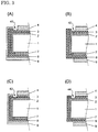
- FIGS. 3(A) to 3(D) are schematic sectional views each showing a deposition state in the vicinity of peripheral portion of the substrate before formation of the plated metal electrode in the process of manufacturing the crystalline silicon solar cell according to the present invention.
- At least the first intrinsic silicon-based thin-film 2 is provided on the insulating regions 41 to 44 at the peripheral edge of the first principal surface, and neither of the first transparent electrode layer 4 and the second transparent electrode layer 9 is provided on the insulation regions.
- the entire first principal surface, the entire second principal surface and the side surface of the crystalline silicon substrate 1 are covered with the silicon-based thin-film, and the insulating region freed of a short-circuit between the first transparent electrode layer and the second transparent electrode layer is formed at the peripheral edge of the first principal surface.
- the first intrinsic silicon-based thin-film 2 and the p-type silicon-based thin-film 3 are formed on the entire first principal surface and the side surface
- the second intrinsic silicon-based thin-film 7, the n-type silicon-based thin-film 8 and the second transparent electrode layer 9 are formed on the entire second principal surface and the side surface.
- the first transparent electrode layer 4 is formed on the entire region of the first principal surface except for the peripheral edge thereof, and is not formed on the side surface.
- an insulating region 41 on which neither of the first transparent electrode layer 4 and the second transparent electrode layer 9 is formed, is provided at the peripheral edge of the first principal surface.
- the insulating region 41 in this form can be produced, for example, in a case where deposition of the silicon-based thin-films 2, 3, 7 and 8 and the second transparent electrode layer 9 are performed without using a mask, and deposition of the first transparent electrode layer 4 is performed under a state in which the peripheral edge of the first principal surface is covered with a mask.
- an insulating region 42 can be formed at the peripheral edge of the first principal surface as shown in FIG. 3(B) .
- insulating regions 43 and 44 on which the intrinsic silicon-based thin-film 2 is formed and neither of the transparent electrode layer and the conductive silicon-based thin-film is formed, is provided at the peripheral edge of the first principal surface.
- the insulating regions 43 and 44 in these forms can be produced in a case where deposition of the p-type silicon-based thin-film is performed under a state in which the peripheral edge of the first principal surface is covered with a mask.
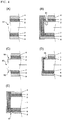
- FIGS. 4(A) to 4(E) associated with a comparative example Examples of the method for eliminating leakage between the first transparent electrode layer and the second transparent electrode layer include a method in which the peripheral portion of a substrate is cleaved and removed by laser irradiation. In this case, the side surface of the n-type crystalline silicon substrate 1 is exposed at an insulating region 91, as shown in FIG. 4(A) .
- the transparent electrode layer 4 is removed by laser irradiation to form an insulating region, it is difficult to remove only the transparent electrode layer 4.
- FIG. 4(B) a groove extends to the silicon substrate 1, so that in an insulating region 92, the n-type crystalline silicon substrate 1 is exposed.
- the metal When a metal is precipitated on the first principal surface, the metal causes shading to reduce the amount of light taken into the n-type crystalline silicon substrate 1 from the light-receiving surface (first principal surface), so that the current density of the solar cell is decreased.
- the exposed portion of the silicon substrate comes into contact with a plating solution in electroplating, metal ions in the plating solution are diffused into the silicon substrate to deteriorate conversion characteristics.
- insulating regions 93, 94 and 95 at which the silicon substrate is exposed are formed on the side surface, on the peripheral edge of the first principal surface and on the peripheral edge of the second principal surface.
- This form can be provided in a case where the silicon-based thin-films 2 and 3 and the transparent electrode layer 4 are deposited under a state in which the peripheral edge of the first principal surface is covered, and the silicon-based thin-films 7 and 8 and the transparent electrode layer 9 are deposited under a state in which the peripheral edge of the second principal surface is covered.
- an insulating region 96 at which the silicon substrate is exposed is provided on the peripheral edge of the first principal surface.
- the insulating region 96 in this form can be produced in a case where the silicon-based thin-films 2 and 3 and the transparent electrode layer 4 are deposited under a state in which the peripheral edge of the first principal surface is covered, and a mask is not used during formation of the silicon-based thin-films 7 and 8 and the transparent electrode layer 9 on the second principal surface.
- precipitation of a metal on the insulating region and diffusion of metal ions in the plating solution into the silicon substrate occur when electroplating is performed by applying a current to the second transparent electrode layer 9.
- an insulating region 97 on which the second intrinsic silicon-based thin-film 7 and the n-type silicon-based thin-film 8 are formed and the transparent electrode layer 9 is not formed, is provided at the peripheral edge of the second principal surface.
- the insulating region 97 in this form can be produced in a case where formation of the silicon-based thin-films 2 and 3 and the transparent electrode layer 4 on the first principal surface and formation of the silicon-based thin-films 7 and 8 on the second principal surface are performed without using mask, and the second transparent electrode layer 9 is formed under a state in which the peripheral edge of the second principal surface is covered with a mask.
- the silicon-based thin-film is formed on the peripheral edge of the first principal surface, and insulating regions 41 to 44, on which neither of the transparent electrode layers 4 and 9 is formed, are provided on the first principal surface. It can be understood that, in these forms, precipitation of a metal on the insulating region due to leakage does not occur even when electroplating is performed by applying a current to the second transparent electrode layer 9. Since the side surface of the silicon substrate 1 is covered with the silicon-based thin-film, ingress of moisture etc. from the side surface is suppressed in practical use of the solar cell.
- FIGS. 3(A) to 3(D) show a form in which deposition of the p-type silicon-based thin-film 3 is performed before deposition of the n-type silicon-based thin-film 8 so that the p-type silicon-based thin-film 3 is situated closer to the n-type crystalline silicon substrate 1 than the n-type silicon-based thin-film 8 on the side surface of the n-type crystalline silicon substrate 1.
- deposition of the n-type silicon-based thin-film 8 may be performed before deposition of the p-type silicon-based thin-film 3 so that the n-type silicon-based thin-film 8 is situated closer to the n-type crystalline silicon substrate 1 than the p-type silicon-based thin-film 3 as shown in FIG.
- a leakage pass exists at a n/n/p junction portion composed of the n-type silicon-based thin-film 8, the n-type crystalline silicon substrate 1 and the p-type silicon-based thin-film 3 as shown with a dashed line arrow in FIG. 5 , and therefore a plated metal may be slightly precipitated at the exposed portion of the p-type silicon-based thin-film 3 of the insulating region 46 to cause shading etc.
- the precipitated metal on the silicon-based thin-film may be removed by air blowing etc., and therefore influences of the precipitated metal are smaller than each of the forms in FIGS. 4(A) to 4(D) .
- the silicon-based thin-film is protected from a plating solution by a conductive oxide that forms the transparent electrode layer.
- a conductive oxide that forms the transparent electrode layer.
- the plated metal electrode 21 is formed by electroplating in addition to the silicon-based thin-film and the second transparent electrode layer 9, and therefore ingress of moisture etc. from the side surface is further suppressed in practical use of the solar cell.
- the second transparent electrode layer Since it is not required to use a mask during deposition of the second transparent electrode layer 9, steps for covering with the mask and alignment of the mask are unnecessary, so that production efficiency can be improved. Further, the second transparent electrode layer is also formed on the peripheral edge of the second principal surface, and therefore carrier collection efficiency on the second principal surface is improved.
- the first intrinsic silicon-based thin-film 2 and the p-type silicon-based thin-film 3 can be successively deposition, and therefore production efficiency can be further improved.
- the deposition of the p-type silicon-based thin-film 3 is performed under a state in which the peripheral edge of the first principal surface is covered with a mask, leakage between the p-type silicon-based thin-film 3 and the n-type silicon-based thin-film 8 can be prevented as shown in FIG. 3(C) , and therefore conversion efficiency can be improved.
- the silicon-based thin-films 2, 3, 7 and 8 and the transparent electrode layers 4 and 9 are formed on the n-type crystalline silicon substrate 1, and the plated metal electrode 21 is then formed on the second transparent electrode layer 9 by electroplating.
- the plated metal electrode 21 is formed on the entire second principal surface, and thus light which has arrived at the second principal surface without being absorbed by the silicon substrate is reflected to reenter into the silicon substrate, so that light utilization efficiency can be improved.
- silicon has a small light absorption coefficient on a near-infrared to long wavelength side
- light utilization efficiency is improved by a plated metal electrode using a material with high reflectivity to light having a wavelength in a near-infrared to infrared range.
- the plated metal electrode 21 is formed on the second transparent electrode layer 9 mainly composed of a conductive metal oxide, so that adhesion between the silicon-based thin-film and the electrode is improved, and the contact resistance is reduced. Since the second transparent electrode layer 9 is provided, diffusion of a metal component to the silicon-based thin-film and the silicon substrate from the plated metal electrode 21 and an underlying metal layer 25 is suppressed, and therefore conversion characteristics can be improved.
- the underlying metal layer 25 may be formed on the second transparent electrode layer 9 before formation of the plated metal electrode as shown in FIG. 6 .
- the conductivity of the surface can be enhanced to improve efficiency of electroplating.
- the second transparent electrode layer 9 can be protected from a plating solution by the underlying metal layer 25.
- the second transparent electrode layer 9 is made of an amorphous conductive metal oxide, it has low durability to the plating solution, and therefore it is preferable that the underlying metal layer 25 is formed for preventing erosion of the second transparent electrode layer 9 by the plating solution.
- a metallic material that forms the underlying metal layer 25 copper, nickel, tin, aluminum, chromium, silver, gold, zinc, lead, palladium or the like, or an alloy thereof can be used.
- the method for forming the underlying metal layer 25 is not particularly limited, a dry process such as a sputtering method or a vapor deposition method, or electroless plating is preferable for efficiently covering the entire surface of the second transparent electrode layer 9.
- a sputtering method is employed, the second transparent electrode layer 9 and the underlying metal layer 25 can be also successively formed.
- the thickness of the underlying metal layer 25 is not particularly limited, it is preferably 200 nm or less, more preferably 100 nm or less, further preferably 60 nm or less from the viewpoint of productivity.
- the thickness of the underlying metal layer 25 is preferably 50% or less, more preferably 30% or less, further preferably 20% or less of the thickness of the plated metal electrode.
- the the thickness of the underlying metal layer 25 is preferably 10 nm or more, more preferably 20 nm or more, further preferably 30 nm or more.
- Material of the plated metal electrode 21 is not particularly limited as long as it is a material that can be deposited by a plating method.
- copper, nickel, tin, aluminum, chromium, silver, gold, zinc, lead, palladium, and alloys thereof may be precipitated as the plated metal electrode 21.
- copper or an alloy including copper as a main component is preferable for the metal that forms the plated metal electrode due to high precipitation rate in electroplating, high electroconductivity and low material cost.
- Formation of the plated metal electrode is performed by immersing an anode in a plating solution, and applying a voltage between the anode and the second transparent electrode layer with the second transparent electrode layer 9 (or the underlying metal layer 25 formed on the surface thereof) brought into contact with the plating solution.
- a plated metal electrode including copper as a main component can be formed by, for example, an acidic copper plating.
- a plating solution used for acidic copper plating contains copper ions, and a solution of known composition, which includes copper sulfate, sulfuric acid and water as main components, can be used. Copper can be precipitated on the second transparent electrode layer 9 by causing a current of 0.1 to 10 A/dm 2 to pass the plating solution.
- the suitable plating time is appropriately set according to the area of the electrode, the current density, cathode current efficiency, desired thickness and so on.
- the plated metal electrode may be a stack of a plurality of layers. For example, by forming a first plating layer made of a material having a high electroconductivity, such as copper, and then forming a metal layer that has higher chemical stability than the first plated metal layer, a back metal electrode having low resistance and being excellent in chemical stability can be formed.
- a first plating layer made of a material having a high electroconductivity, such as copper
- a plating solution remaining on the surface after formation of the plated metal electrode by electroplating.
- a metal precipitated on the surfaces of the exposed portions of the intrinsic silicon-based thin-film 2 and the p-type silicon-based thin-film insulating regions 41 to 44 and 46 of the peripheral edge of the first principal surface; see FIGS. 3(A) to 3(D) , FIG. 5 and FIG. 6 ), the end surfaces of the second transparent electrode layer 9, and so on can also be removed together.
- Removal of the plating solution can be performed by, for example, a method in which plating solution remaining on the surface of the substrate taken out from a plating tank is removed by air blow-type air washing, rinsing is then carried out, and a washing fluid is blown off by air blow.
- the patterned collecting electrode 11 is formed on the first transparent electrode layer 4 of the first principal surface.
- the method for forming the patterned collecting electrode is not particularly limited, and the patterned collecting electrode can be formed by a plating method, a printing method such as inkjet printing or screen printing, a conductor bonding method or the like.
- a printing method such as inkjet printing or screen printing
- a conductor bonding method or the like For example, in the screen printing method, a process in which a conductive paste composed of metal particles and a resin binder is applied by screen printing is preferably used.
- a patterned collecting electrode can be formed by plating under a state in which the first transparent electrode layer is covered with a resist having an opening corresponding to the pattern shape of the collecting electrode.
- the patterned collecting electrode 11 may be formed by depositing a metal with an opening section of an insulating layer as an origination point for plating, the insulating layer being formed on the underlying metal layer.
- the patterned collecting electrode 11 is formed by electroplating, it is preferable that electroplating is performed in a state in which the first transparent electrode layer and the second transparent electrode layer are not short-circuited (an insulating region is formed as described above) for suppressing precipitation of an undesired metal on the side surface and the second principal surface.
- Formation of the patterned collecting electrode 11 on the first principal surface may be performed before or after formation of the plated metal electrode 21 on the second principal surface.
- formation of the patterned collecting electrode 11 can be performed simultaneously with formation of the plated metal electrode 21.
- the plated metal layer 21 and the patterned collecting electrode can be simultaneously formed. According to this method, the number of steps of forming an electrode layer by plating can be reduced, so that productivity can be improved.
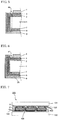
- FIG. 7 is a schematic sectional view showing a solar cell module of one embodiment.
- the solar cell module includes a wiring member 150 for electrically connecting a solar cell to an external circuit.
- a plurality of solar cells 100 are electrically connected via an interconnector 155 as shown in FIG. 7 .
- a solar cell string in which a plurality of solar cells 100 are mutually connected via the interconnector 155 is prepared.
- the collecting electrode 11 of one solar cell and the plated metal layer 21 of the adjacent solar cell are connected via the interconnector 155.
- the wiring member 150 is connected to solar cells 100 at both ends, which form the solar cell string.
- the electrode of the solar cell and the wiring member are connected via, for example, an appropriate adhesive (not illustrated).
- the solar cell 100 is sandwiched between protective materials 131 and 132 with a sealing material 120 interposed between the solar cell 100 and the protective materials 131 and 132, so that a solar cell module is formed.
- the protective materials 131 and 132 are arranged on the light-receiving side and the back side, respectively, of the solar cell 100 with the sealing material interposed therebetween, so that a laminated body is obtained, and thereafter the laminated body is heated under a predetermined condition, whereby the sealing material 120 is cured to perform sealing. Then, an Al frame (not illustrated) etc. is attached to prepare the solar cell module.
- the protective material 131 on the light-receiving side a material having translucency and water impermeability such as a glass, a transparent plastic, or the like can be used.
- a resin film such as PET film, a laminated film having a structure with an Al foil sandwiched by resin films, or the like can be used.
- the sealing material 120 seals the solar cell 100 between the protective materials 131 and 132 on the light receiving surface and the back surface.
- a transparent resin such as EVA, EEA, PVB, silicone, urethane, acryl, epoxy, or the like can be used.
- the solar cell is sealed in the above-described manner to suppress ingress of external moisture etc. into the solar cell, so that the long-term reliability of the solar cell module can be improved.
- the protective materials 131 and 132 are adhesively stacked on the light-receiving side and the back side, respectively, of the solar cell 100 with the sealing material 120 interposed therebetween, whereas the side surface of the solar cell is only protected by the sealing material.
- the silicon-based thin-film is also formed on the side surface of the crystalline silicon substrate 1, and therefore ingress of moisture etc. into the crystalline silicon substrate from the side surface of the solar cell is suppressed.
- the plated metal electrode 21 is also formed on the side surface of the solar cell as shown in FIG. 7 , ingress of moisture etc. from the side surface can be further suppressed, so that the long-term reliability of the solar cell module can be further improved.
Landscapes
- Photovoltaic Devices (AREA)
- Life Sciences & Earth Sciences (AREA)
- Engineering & Computer Science (AREA)
- Sustainable Energy (AREA)
- Sustainable Development (AREA)
Applications Claiming Priority (2)
| Application Number | Priority Date | Filing Date | Title |
|---|---|---|---|
| JP2014095543 | 2014-05-02 | ||
| PCT/JP2015/061160 WO2015166780A1 (ja) | 2014-05-02 | 2015-04-09 | 結晶シリコン系太陽電池、結晶シリコン系太陽電池モジュール、およびそれらの製造方法 |
Publications (3)
| Publication Number | Publication Date |
|---|---|
| EP3136451A1 true EP3136451A1 (de) | 2017-03-01 |
| EP3136451A4 EP3136451A4 (de) | 2018-01-17 |
| EP3136451B1 EP3136451B1 (de) | 2020-04-01 |
Family
ID=54358515
Family Applications (1)
| Application Number | Title | Priority Date | Filing Date |
|---|---|---|---|
| EP15785959.6A Active EP3136451B1 (de) | 2014-05-02 | 2015-04-09 | Solarzelle mit kristallinem silicium, solarzellenmodul mit kristallinem silicium und herstellungsverfahren dafür |
Country Status (5)
| Country | Link |
|---|---|
| US (1) | US10217887B2 (de) |
| EP (1) | EP3136451B1 (de) |
| JP (1) | JP6568518B2 (de) |
| CN (1) | CN106463561B (de) |
| WO (1) | WO2015166780A1 (de) |
Cited By (1)
| Publication number | Priority date | Publication date | Assignee | Title |
|---|---|---|---|---|
| EP4418333A3 (de) * | 2023-12-19 | 2025-02-19 | Trina Solar Co., Ltd | Heteroübergangszelle und herstellungsverfahren dafür, fotovoltaisches modul und fotovoltaisches system |
Families Citing this family (9)
| Publication number | Priority date | Publication date | Assignee | Title |
|---|---|---|---|---|
| US10008622B2 (en) * | 2015-03-31 | 2018-06-26 | Kaneka Corporation | Solar cell, method for manufacturing same, solar cell module and wiring sheet |
| CN108886069B (zh) * | 2016-04-13 | 2022-01-14 | 株式会社钟化 | 晶体硅系太阳能电池及其制造方法、以及太阳能电池模块 |
| JP2019021599A (ja) | 2017-07-21 | 2019-02-07 | 株式会社東芝 | 透明電極、およびその製造方法、ならびにその透明電極を用いた電子デバイス |
| CN108321239A (zh) * | 2017-12-21 | 2018-07-24 | 君泰创新(北京)科技有限公司 | 一种太阳能异质结电池及其制备方法 |
| DE102018116466B3 (de) * | 2018-07-06 | 2019-06-19 | Solibro Hi-Tech Gmbh | Dünnschichtsolarmodul und Verfahren zur Herstellung eines Dünnschichtsolarmoduls |
| CN109961870A (zh) * | 2019-03-01 | 2019-07-02 | 泰州中来光电科技有限公司 | 一种晶体硅太阳电池用黑色银浆及其制备方法 |
| CN114649438B (zh) * | 2020-12-17 | 2024-05-10 | 浙江爱旭太阳能科技有限公司 | 一种n型hibc太阳电池的制备方法 |
| CN114649422B (zh) * | 2020-12-17 | 2024-05-10 | 浙江爱旭太阳能科技有限公司 | 一种硅基异质结太阳电池结构及制备方法 |
| JP7114821B1 (ja) | 2022-03-18 | 2022-08-08 | 株式会社東芝 | 多層接合型光電変換素子及び多層接合型光電変換素子の製造方法 |
Family Cites Families (7)
| Publication number | Priority date | Publication date | Assignee | Title |
|---|---|---|---|---|
| JP3349308B2 (ja) * | 1995-10-26 | 2002-11-25 | 三洋電機株式会社 | 光起電力素子 |
| CN101281936B (zh) * | 2008-04-24 | 2011-05-11 | 珈伟太阳能(武汉)有限公司 | 单面指状交叉式太阳能电池片的切割方法 |
| EP2450970A1 (de) * | 2010-11-05 | 2012-05-09 | Roth & Rau AG | Kantenisolierung mittels Abziehen |
| JP2013012606A (ja) | 2011-06-29 | 2013-01-17 | Sanyo Electric Co Ltd | 太陽電池及びその製造方法 |
| JP2013058702A (ja) * | 2011-09-09 | 2013-03-28 | Mitsubishi Electric Corp | 太陽電池セルおよびその製造方法、太陽電池モジュールおよびその製造方法 |
| WO2013161127A1 (ja) * | 2012-04-25 | 2013-10-31 | 株式会社カネカ | 太陽電池およびその製造方法、ならびに太陽電池モジュール |
| US20150270422A1 (en) | 2012-10-02 | 2015-09-24 | Kaneka Corporation | Method for producing crystalline silicon solar cell, method for producing solar cell module, crystalline silicon solar cell, and solar cell module |
-
2015
- 2015-04-09 WO PCT/JP2015/061160 patent/WO2015166780A1/ja not_active Ceased
- 2015-04-09 CN CN201580022564.8A patent/CN106463561B/zh active Active
- 2015-04-09 EP EP15785959.6A patent/EP3136451B1/de active Active
- 2015-04-09 US US15/308,030 patent/US10217887B2/en active Active
- 2015-04-09 JP JP2016515913A patent/JP6568518B2/ja active Active
Cited By (1)
| Publication number | Priority date | Publication date | Assignee | Title |
|---|---|---|---|---|
| EP4418333A3 (de) * | 2023-12-19 | 2025-02-19 | Trina Solar Co., Ltd | Heteroübergangszelle und herstellungsverfahren dafür, fotovoltaisches modul und fotovoltaisches system |
Also Published As
| Publication number | Publication date |
|---|---|
| CN106463561A (zh) | 2017-02-22 |
| US20170084772A1 (en) | 2017-03-23 |
| CN106463561B (zh) | 2019-02-05 |
| JPWO2015166780A1 (ja) | 2017-04-20 |
| US10217887B2 (en) | 2019-02-26 |
| EP3136451B1 (de) | 2020-04-01 |
| WO2015166780A1 (ja) | 2015-11-05 |
| JP6568518B2 (ja) | 2019-08-28 |
| EP3136451A4 (de) | 2018-01-17 |
Similar Documents
| Publication | Publication Date | Title |
|---|---|---|
| EP3136451B1 (de) | Solarzelle mit kristallinem silicium, solarzellenmodul mit kristallinem silicium und herstellungsverfahren dafür | |
| US10388821B2 (en) | Method for manufacturing crystalline silicon-based solar cell and method for manufacturing crystalline silicon-based solar cell module | |
| US9761752B2 (en) | Solar cell, solar cell module, method for manufacturing solar cell, and method for manufacturing solar cell module | |
| WO2011115206A1 (ja) | 太陽電池、その太陽電池を用いた太陽電池モジュール及び太陽電池の製造方法 | |
| US10879409B2 (en) | Crystalline silicon solar cell, production method therefor, and solar cell module | |
| CN107112378A (zh) | 太阳能电池及其制造方法、以及太阳能电池模块 | |
| KR101114099B1 (ko) | 태양광 발전장치 및 이의 제조방법 | |
| CN102782874B (zh) | 太阳能电池设备及其制造方法 | |
| EP2600422A2 (de) | Vorrichtung zur solarstromgewinnung und herstellungsverfahren dafür | |
| KR20130109330A (ko) | 태양전지 및 이의 제조 방법 | |
| KR101241467B1 (ko) | 태양전지 및 이의 제조방법 | |
| KR101251841B1 (ko) | 태양광 발전장치 및 이의 제조방법 | |
| KR20130040015A (ko) | 태양전지 및 이의 제조방법 | |
| KR101338610B1 (ko) | 태양광 발전장치 및 이의 제조방법 | |
| KR20130136739A (ko) | 태양전지 및 이의 제조방법 | |
| JP2014007236A (ja) | 集積化太陽電池およびその製造方法 | |
| JP5935047B2 (ja) | 太陽電池、太陽電池モジュール及び太陽電池の製造方法 | |
| JP6191995B2 (ja) | 太陽電池モジュール |
Legal Events
| Date | Code | Title | Description |
|---|---|---|---|
| STAA | Information on the status of an ep patent application or granted ep patent |
Free format text: STATUS: THE INTERNATIONAL PUBLICATION HAS BEEN MADE |
|
| PUAI | Public reference made under article 153(3) epc to a published international application that has entered the european phase |
Free format text: ORIGINAL CODE: 0009012 |
|
| STAA | Information on the status of an ep patent application or granted ep patent |
Free format text: STATUS: REQUEST FOR EXAMINATION WAS MADE |
|
| 17P | Request for examination filed |
Effective date: 20161118 |
|
| AK | Designated contracting states |
Kind code of ref document: A1 Designated state(s): AL AT BE BG CH CY CZ DE DK EE ES FI FR GB GR HR HU IE IS IT LI LT LU LV MC MK MT NL NO PL PT RO RS SE SI SK SM TR |
|
| AX | Request for extension of the european patent |
Extension state: BA ME |
|
| DAV | Request for validation of the european patent (deleted) | ||
| DAX | Request for extension of the european patent (deleted) | ||
| A4 | Supplementary search report drawn up and despatched |
Effective date: 20171219 |
|
| RIC1 | Information provided on ipc code assigned before grant |
Ipc: H01L 31/0224 20060101ALI20171213BHEP Ipc: H01L 31/0747 20120101AFI20171213BHEP |
|
| GRAP | Despatch of communication of intention to grant a patent |
Free format text: ORIGINAL CODE: EPIDOSNIGR1 |
|
| STAA | Information on the status of an ep patent application or granted ep patent |
Free format text: STATUS: GRANT OF PATENT IS INTENDED |
|
| INTG | Intention to grant announced |
Effective date: 20191129 |
|
| GRAS | Grant fee paid |
Free format text: ORIGINAL CODE: EPIDOSNIGR3 |
|
| GRAA | (expected) grant |
Free format text: ORIGINAL CODE: 0009210 |
|
| STAA | Information on the status of an ep patent application or granted ep patent |
Free format text: STATUS: THE PATENT HAS BEEN GRANTED |
|
| AK | Designated contracting states |
Kind code of ref document: B1 Designated state(s): AL AT BE BG CH CY CZ DE DK EE ES FI FR GB GR HR HU IE IS IT LI LT LU LV MC MK MT NL NO PL PT RO RS SE SI SK SM TR |
|
| REG | Reference to a national code |
Ref country code: GB Ref legal event code: FG4D |
|
| REG | Reference to a national code |
Ref country code: CH Ref legal event code: EP Ref country code: AT Ref legal event code: REF Ref document number: 1252499 Country of ref document: AT Kind code of ref document: T Effective date: 20200415 |
|
| REG | Reference to a national code |
Ref country code: DE Ref legal event code: R096 Ref document number: 602015049920 Country of ref document: DE |
|
| REG | Reference to a national code |
Ref country code: IE Ref legal event code: FG4D |
|
| PG25 | Lapsed in a contracting state [announced via postgrant information from national office to epo] |
Ref country code: BG Free format text: LAPSE BECAUSE OF FAILURE TO SUBMIT A TRANSLATION OF THE DESCRIPTION OR TO PAY THE FEE WITHIN THE PRESCRIBED TIME-LIMIT Effective date: 20200701 |
|
| REG | Reference to a national code |
Ref country code: NL Ref legal event code: MP Effective date: 20200401 |
|
| REG | Reference to a national code |
Ref country code: LT Ref legal event code: MG4D |
|
| PG25 | Lapsed in a contracting state [announced via postgrant information from national office to epo] |
Ref country code: LT Free format text: LAPSE BECAUSE OF FAILURE TO SUBMIT A TRANSLATION OF THE DESCRIPTION OR TO PAY THE FEE WITHIN THE PRESCRIBED TIME-LIMIT Effective date: 20200401 Ref country code: GR Free format text: LAPSE BECAUSE OF FAILURE TO SUBMIT A TRANSLATION OF THE DESCRIPTION OR TO PAY THE FEE WITHIN THE PRESCRIBED TIME-LIMIT Effective date: 20200702 Ref country code: NO Free format text: LAPSE BECAUSE OF FAILURE TO SUBMIT A TRANSLATION OF THE DESCRIPTION OR TO PAY THE FEE WITHIN THE PRESCRIBED TIME-LIMIT Effective date: 20200701 Ref country code: FI Free format text: LAPSE BECAUSE OF FAILURE TO SUBMIT A TRANSLATION OF THE DESCRIPTION OR TO PAY THE FEE WITHIN THE PRESCRIBED TIME-LIMIT Effective date: 20200401 Ref country code: SE Free format text: LAPSE BECAUSE OF FAILURE TO SUBMIT A TRANSLATION OF THE DESCRIPTION OR TO PAY THE FEE WITHIN THE PRESCRIBED TIME-LIMIT Effective date: 20200401 Ref country code: IS Free format text: LAPSE BECAUSE OF FAILURE TO SUBMIT A TRANSLATION OF THE DESCRIPTION OR TO PAY THE FEE WITHIN THE PRESCRIBED TIME-LIMIT Effective date: 20200801 Ref country code: CZ Free format text: LAPSE BECAUSE OF FAILURE TO SUBMIT A TRANSLATION OF THE DESCRIPTION OR TO PAY THE FEE WITHIN THE PRESCRIBED TIME-LIMIT Effective date: 20200401 Ref country code: PT Free format text: LAPSE BECAUSE OF FAILURE TO SUBMIT A TRANSLATION OF THE DESCRIPTION OR TO PAY THE FEE WITHIN THE PRESCRIBED TIME-LIMIT Effective date: 20200817 Ref country code: NL Free format text: LAPSE BECAUSE OF FAILURE TO SUBMIT A TRANSLATION OF THE DESCRIPTION OR TO PAY THE FEE WITHIN THE PRESCRIBED TIME-LIMIT Effective date: 20200401 |
|
| REG | Reference to a national code |
Ref country code: AT Ref legal event code: MK05 Ref document number: 1252499 Country of ref document: AT Kind code of ref document: T Effective date: 20200401 |
|
| PG25 | Lapsed in a contracting state [announced via postgrant information from national office to epo] |
Ref country code: LV Free format text: LAPSE BECAUSE OF FAILURE TO SUBMIT A TRANSLATION OF THE DESCRIPTION OR TO PAY THE FEE WITHIN THE PRESCRIBED TIME-LIMIT Effective date: 20200401 Ref country code: RS Free format text: LAPSE BECAUSE OF FAILURE TO SUBMIT A TRANSLATION OF THE DESCRIPTION OR TO PAY THE FEE WITHIN THE PRESCRIBED TIME-LIMIT Effective date: 20200401 Ref country code: HR Free format text: LAPSE BECAUSE OF FAILURE TO SUBMIT A TRANSLATION OF THE DESCRIPTION OR TO PAY THE FEE WITHIN THE PRESCRIBED TIME-LIMIT Effective date: 20200401 |
|
| REG | Reference to a national code |
Ref country code: CH Ref legal event code: PL |
|
| PG25 | Lapsed in a contracting state [announced via postgrant information from national office to epo] |
Ref country code: AL Free format text: LAPSE BECAUSE OF FAILURE TO SUBMIT A TRANSLATION OF THE DESCRIPTION OR TO PAY THE FEE WITHIN THE PRESCRIBED TIME-LIMIT Effective date: 20200401 |
|
| REG | Reference to a national code |
Ref country code: DE Ref legal event code: R097 Ref document number: 602015049920 Country of ref document: DE |
|
| PG25 | Lapsed in a contracting state [announced via postgrant information from national office to epo] |
Ref country code: LU Free format text: LAPSE BECAUSE OF NON-PAYMENT OF DUE FEES Effective date: 20200409 Ref country code: IT Free format text: LAPSE BECAUSE OF FAILURE TO SUBMIT A TRANSLATION OF THE DESCRIPTION OR TO PAY THE FEE WITHIN THE PRESCRIBED TIME-LIMIT Effective date: 20200401 Ref country code: LI Free format text: LAPSE BECAUSE OF NON-PAYMENT OF DUE FEES Effective date: 20200430 Ref country code: MC Free format text: LAPSE BECAUSE OF FAILURE TO SUBMIT A TRANSLATION OF THE DESCRIPTION OR TO PAY THE FEE WITHIN THE PRESCRIBED TIME-LIMIT Effective date: 20200401 Ref country code: CH Free format text: LAPSE BECAUSE OF NON-PAYMENT OF DUE FEES Effective date: 20200430 Ref country code: DK Free format text: LAPSE BECAUSE OF FAILURE TO SUBMIT A TRANSLATION OF THE DESCRIPTION OR TO PAY THE FEE WITHIN THE PRESCRIBED TIME-LIMIT Effective date: 20200401 Ref country code: SM Free format text: LAPSE BECAUSE OF FAILURE TO SUBMIT A TRANSLATION OF THE DESCRIPTION OR TO PAY THE FEE WITHIN THE PRESCRIBED TIME-LIMIT Effective date: 20200401 Ref country code: EE Free format text: LAPSE BECAUSE OF FAILURE TO SUBMIT A TRANSLATION OF THE DESCRIPTION OR TO PAY THE FEE WITHIN THE PRESCRIBED TIME-LIMIT Effective date: 20200401 Ref country code: AT Free format text: LAPSE BECAUSE OF FAILURE TO SUBMIT A TRANSLATION OF THE DESCRIPTION OR TO PAY THE FEE WITHIN THE PRESCRIBED TIME-LIMIT Effective date: 20200401 Ref country code: ES Free format text: LAPSE BECAUSE OF FAILURE TO SUBMIT A TRANSLATION OF THE DESCRIPTION OR TO PAY THE FEE WITHIN THE PRESCRIBED TIME-LIMIT Effective date: 20200401 Ref country code: RO Free format text: LAPSE BECAUSE OF FAILURE TO SUBMIT A TRANSLATION OF THE DESCRIPTION OR TO PAY THE FEE WITHIN THE PRESCRIBED TIME-LIMIT Effective date: 20200401 |
|
| REG | Reference to a national code |
Ref country code: BE Ref legal event code: MM Effective date: 20200430 |
|
| PLBE | No opposition filed within time limit |
Free format text: ORIGINAL CODE: 0009261 |
|
| STAA | Information on the status of an ep patent application or granted ep patent |
Free format text: STATUS: NO OPPOSITION FILED WITHIN TIME LIMIT |
|
| PG25 | Lapsed in a contracting state [announced via postgrant information from national office to epo] |
Ref country code: SK Free format text: LAPSE BECAUSE OF FAILURE TO SUBMIT A TRANSLATION OF THE DESCRIPTION OR TO PAY THE FEE WITHIN THE PRESCRIBED TIME-LIMIT Effective date: 20200401 Ref country code: PL Free format text: LAPSE BECAUSE OF FAILURE TO SUBMIT A TRANSLATION OF THE DESCRIPTION OR TO PAY THE FEE WITHIN THE PRESCRIBED TIME-LIMIT Effective date: 20200401 Ref country code: BE Free format text: LAPSE BECAUSE OF NON-PAYMENT OF DUE FEES Effective date: 20200430 |
|
| 26N | No opposition filed |
Effective date: 20210112 |
|
| GBPC | Gb: european patent ceased through non-payment of renewal fee |
Effective date: 20200701 |
|
| PG25 | Lapsed in a contracting state [announced via postgrant information from national office to epo] |
Ref country code: IE Free format text: LAPSE BECAUSE OF NON-PAYMENT OF DUE FEES Effective date: 20200409 Ref country code: GB Free format text: LAPSE BECAUSE OF NON-PAYMENT OF DUE FEES Effective date: 20200701 Ref country code: FR Free format text: LAPSE BECAUSE OF NON-PAYMENT OF DUE FEES Effective date: 20200601 |
|
| PG25 | Lapsed in a contracting state [announced via postgrant information from national office to epo] |
Ref country code: SI Free format text: LAPSE BECAUSE OF FAILURE TO SUBMIT A TRANSLATION OF THE DESCRIPTION OR TO PAY THE FEE WITHIN THE PRESCRIBED TIME-LIMIT Effective date: 20200401 |
|
| PG25 | Lapsed in a contracting state [announced via postgrant information from national office to epo] |
Ref country code: TR Free format text: LAPSE BECAUSE OF FAILURE TO SUBMIT A TRANSLATION OF THE DESCRIPTION OR TO PAY THE FEE WITHIN THE PRESCRIBED TIME-LIMIT Effective date: 20200401 Ref country code: MT Free format text: LAPSE BECAUSE OF FAILURE TO SUBMIT A TRANSLATION OF THE DESCRIPTION OR TO PAY THE FEE WITHIN THE PRESCRIBED TIME-LIMIT Effective date: 20200401 Ref country code: CY Free format text: LAPSE BECAUSE OF FAILURE TO SUBMIT A TRANSLATION OF THE DESCRIPTION OR TO PAY THE FEE WITHIN THE PRESCRIBED TIME-LIMIT Effective date: 20200401 |
|
| PG25 | Lapsed in a contracting state [announced via postgrant information from national office to epo] |
Ref country code: MK Free format text: LAPSE BECAUSE OF FAILURE TO SUBMIT A TRANSLATION OF THE DESCRIPTION OR TO PAY THE FEE WITHIN THE PRESCRIBED TIME-LIMIT Effective date: 20200401 |
|
| REG | Reference to a national code |
Ref country code: DE Ref legal event code: R079 Ref document number: 602015049920 Country of ref document: DE Free format text: PREVIOUS MAIN CLASS: H01L0031074700 Ipc: H10F0010166000 |
|
| PGFP | Annual fee paid to national office [announced via postgrant information from national office to epo] |
Ref country code: DE Payment date: 20250305 Year of fee payment: 11 |