EP3136031B1 - Gefriertrocknungsanlage umfassend eine übergabeeinheit - Google Patents
Gefriertrocknungsanlage umfassend eine übergabeeinheit Download PDFInfo
- Publication number
- EP3136031B1 EP3136031B1 EP16178380.8A EP16178380A EP3136031B1 EP 3136031 B1 EP3136031 B1 EP 3136031B1 EP 16178380 A EP16178380 A EP 16178380A EP 3136031 B1 EP3136031 B1 EP 3136031B1
- Authority
- EP
- European Patent Office
- Prior art keywords
- loading platform
- door leaf
- freeze drying
- drying device
- adjusting plate
- Prior art date
- Legal status (The legal status is an assumption and is not a legal conclusion. Google has not performed a legal analysis and makes no representation as to the accuracy of the status listed.)
- Not-in-force
Links
- 238000004108 freeze drying Methods 0.000 title claims description 42
- 239000012858 resilient material Substances 0.000 claims description 3
- 229910001220 stainless steel Inorganic materials 0.000 claims description 3
- 239000010935 stainless steel Substances 0.000 claims description 3
- 235000013611 frozen food Nutrition 0.000 description 17
- 239000012530 fluid Substances 0.000 description 6
- 230000007704 transition Effects 0.000 description 5
- IJGRMHOSHXDMSA-UHFFFAOYSA-N Atomic nitrogen Chemical compound N#N IJGRMHOSHXDMSA-UHFFFAOYSA-N 0.000 description 4
- 239000000463 material Substances 0.000 description 4
- 238000011161 development Methods 0.000 description 3
- 230000018109 developmental process Effects 0.000 description 3
- 239000013013 elastic material Substances 0.000 description 2
- 239000007789 gas Substances 0.000 description 2
- 238000009434 installation Methods 0.000 description 2
- 229910052757 nitrogen Inorganic materials 0.000 description 2
- 230000000284 resting effect Effects 0.000 description 2
- 230000001419 dependent effect Effects 0.000 description 1
- 239000000825 pharmaceutical preparation Substances 0.000 description 1
- 229940127557 pharmaceutical product Drugs 0.000 description 1
- 230000000717 retained effect Effects 0.000 description 1
Images




Classifications
-
- F—MECHANICAL ENGINEERING; LIGHTING; HEATING; WEAPONS; BLASTING
- F26—DRYING
- F26B—DRYING SOLID MATERIALS OR OBJECTS BY REMOVING LIQUID THEREFROM
- F26B25/00—Details of general application not covered by group F26B21/00 or F26B23/00
- F26B25/001—Handling, e.g. loading or unloading arrangements
-
- B—PERFORMING OPERATIONS; TRANSPORTING
- B65—CONVEYING; PACKING; STORING; HANDLING THIN OR FILAMENTARY MATERIAL
- B65G—TRANSPORT OR STORAGE DEVICES, e.g. CONVEYORS FOR LOADING OR TIPPING, SHOP CONVEYOR SYSTEMS OR PNEUMATIC TUBE CONVEYORS
- B65G65/00—Loading or unloading
-
- F—MECHANICAL ENGINEERING; LIGHTING; HEATING; WEAPONS; BLASTING
- F26—DRYING
- F26B—DRYING SOLID MATERIALS OR OBJECTS BY REMOVING LIQUID THEREFROM
- F26B25/00—Details of general application not covered by group F26B21/00 or F26B23/00
- F26B25/06—Chambers, containers, or receptacles
- F26B25/08—Parts thereof
- F26B25/12—Walls or sides; Doors
-
- F—MECHANICAL ENGINEERING; LIGHTING; HEATING; WEAPONS; BLASTING
- F26—DRYING
- F26B—DRYING SOLID MATERIALS OR OBJECTS BY REMOVING LIQUID THEREFROM
- F26B5/00—Drying solid materials or objects by processes not involving the application of heat
- F26B5/04—Drying solid materials or objects by processes not involving the application of heat by evaporation or sublimation of moisture under reduced pressure, e.g. in a vacuum
- F26B5/06—Drying solid materials or objects by processes not involving the application of heat by evaporation or sublimation of moisture under reduced pressure, e.g. in a vacuum the process involving freezing
Definitions
- the present invention relates to a transfer unit for providing a transport connection between a frozen food supply system and a freeze dryer according to the preamble of claim 1.
- the US5129162A , the WO2013098834 A1 or the FR 2 780 148 A1 is a freeze-drying plant with a pressure chamber and a number of arranged therein plates for receiving the frozen food known.
- a charging opening is formed in a wall of the pressure chamber, which is closable with a door leaf.
- the frozen food is a pharmaceutical product that is subject to high hygiene requirements, which is why the frozen food supply system must be operated under clean room conditions until the frozen food is properly packaged.
- the frozen food is overflowed during the loading and unloading with a pure fluid, for example, pure air, nitrogen or other gas.
- the interior of the pressure chamber with pure fluid for example, pure air, nitrogen or other gas is applied so strong that exits at the feed opening a predetermined volume flow from the pressure chamber to meet the hygiene requirements.
- the loading bridge is pivotally mounted and can be pivoted into it after opening the loading opening to come to rest on the adjusting plate.
- the feed opening must be designed to be correspondingly high, with the result that a large amount of fluid is required to be present at the feed opening to comply with the hygiene regulations.
- the door leaf must be designed to be stable in order to withstand the pressures occurring in the pressure chamber in the closed state.
- the loading bridge is oriented horizontally and is moved directly through the feed opening to the setting plate.
- the feed opening can be made lower, that is smaller, so that the door leaf can be made much smaller.
- the clean room is correspondingly large to create, with the result that here more fluid to ensure the clean room conditions is required. In addition, this increases the space required.
- the present invention has the object to provide a transfer unit of the type mentioned, so that the freeze-drying plant manages with a small feed opening and so that the Gefriergutzu Glassstrom can be made compact.
- a trained according to this technical teaching transfer unit has the advantage that the loading bridge is decoupled from the Gefriergutzu Swissis, with the result that the Gefriergutzu Foodstrom can be made correspondingly smaller. As a result, the space required before the freeze-drying plant is correspondingly smaller. Another advantage is that the effort to comply with the hygiene requirements can be reduced accordingly, in particular that less fluid is needed.
- a small feed opening has the advantage that less fluid is required to comply with the hygiene regulations, which significantly reduces the operating costs of the freeze-drying plant. Also, in this case the door leaf can be designed correspondingly smaller and damin cost.
- the door leaf is guided over a guide element arranged next to the door leaf.
- a guide element arranged next to the door leaf.
- the loading bridge follows in the course of the guide slot and is guided from its rest position outside the freeze-drying plant when moving the door leaf partially through the feed opening through to the control plate and when closing the door leaf, the loading bridge is returned accordingly to their original position.
- At least one, preferably four, linear bearings are attached to the loading bridge while at least one, preferably two, guide shafts are mounted on the door leaf and wherein the linear bearing is held on the guide shaft, so that the loading bridge is displaceable transversely to the door leaf.
- At least one stop for abutment of the loading bridge is provided on the adjusting plate. In its final position then the loading bridge comes to this stop to the plant.
- the stopper is designed so that the top of the loading bridge is aligned on the upper side of the adjusting plate, so that no disturbing edge remains during transport of the frozen goods.
- the stop comprises a disc, which is held with an eccentrically mounted screw on a side surface of the adjusting plate. Due to the eccentric arrangement of the screw, the disc can be aligned so that the distance of the upper edge of the disc to the top of the adjusting plate corresponds exactly to the thickness of the loading bridge, so that when resting the loading bridge at the stop a smooth transition from the loading bridge is achieved on the setting plate.
- the stop described here is also attached to the frozen food supply system in an analogous manner in order to achieve a smooth transition from the frozen food supply system to the loading bridge there as well.
- the loading bridge is formed of a resilient material, preferably of a stainless steel sheet, with a thickness of 2 mm.
- a loading bridge can be placed on a stop provided on the adjusting plate and held in such a way that the loading bridge is under tension. This can be achieved by moving the door leaf 1 to 5 mm further than actually required.
- Such a biased loading bridge is reliably pressed against the stop due to the elastic properties of the material and thus ensures a precise and vibration-free fit on the shelf, so that the frozen food can pass smoothly from the loading bridge on the shelf.
- At least one spring element is provided between the door leaf and the loading bridge, so that the loading bridge is resiliently retained on the door leaf.
- the loading bridge can be mounted above or below the door leaf.
- FIGS. 1 to 6 a first embodiment of a freeze-drying plant according to the invention is shown.
- This freeze-drying plant comprises a pressure chamber 10, on whose front-side wall 12 a feed opening 14 is provided, which can be closed by a door leaf 16 held on the wall 12.
- a feed opening 14 is provided within the pressure chamber 10 for receiving not shown here in detail frozen goods.
- This actuator plate 18 is located at the level of the feed opening 14 and corresponds to a not shown here Gefriergutzu slaughterhouse, which is arranged in front of the freeze-drying plant.
- a loading bridge 20 is held, which is arranged during the loading of the freeze-drying plant with frozen food flush between the setting plate 18 and a transfer table 22 of the frozen material supply system, as in Fig. 6 is shown.
- a slide 24 belonging to the frozen food supply system can then push a number of vials 26 filled with items to be frozen from the transfer table 22 via the loading bridge 20 onto the setting plate 18.
- two guide shafts 28 are mounted in the form of a rod, which are aligned transversely to the door leaf 16.
- two linear bearings 30 are mounted corresponding to the guide shafts 28, wherein the linear bearings 30 are held on the guide shafts 28, so that the loading bridge 20 is displaceable transversely to the door leaf 16.
- a vertically aligned guide member 32 is mounted, wherein in each guide member 32, two parallel guide slots 34 are provided, in each of which a fastened to the loading bridge 20 pin 36 protrudes.
- the guide slot 34 is aligned so curved that the loading bridge when lowering the door leaf 16 is passed from a starting position outside the freeze dryer partially into the feed opening 14 and is brought up to the setting plate 18 so that in the end position the loading bridge 20 is a connection between the setting plate 18 and the transfer table 22 of the frozen food supply plant produces, as in the FIGS. 3 to 6 is shown schematically.
- a slider 24 can then push the vials 26 filled with frozen food from the transfer table 22 via the loading bridge 20 to the setting plate 18 or in the opposite direction to unload the setting plate 18 accordingly.
- the door leaf 16 is moved upward, the loading bridge 20 is moved from its end position by means of the guide slots 34 through the feed opening 14 to the outside of the freeze-drying plant, so that the Loading bridge 20 is completely disposed outside the freeze-drying plant with the door closed 16.
- each stop 38 comprises a circular disc 40, which is screwed with an eccentrically mounted screw 42 on a side wall of the adjusting plate 18. Due to the eccentric mounting of the disc 40 hereby the distance between an upper edge of the disc 40 and an upper edge of the adjusting plate 18 can be adjusted so that the resting on the disc 40 loading bridge 20 is aligned with its upper edge exactly with the upper edge of the adjusting plate 18 so that a edge-free transition is achieved.
- Such stops 38 is also provided on the transfer table 22 in order to achieve a reliable, precise and low-vibration transition from the loading bridge 20 to the transfer table 22 here as well.
- the loading bridge 20 is formed from a 2 mm stainless steel sheet, so that the loading bridge 20 has elastic properties.
- a spring element 44 is provided between each linear bearing 30 and the loading bridge 20, so that the loading bridge 20 is resiliently held on the door leaf 16. If the loading bridge 20 is now in its end position, the door leaf 16 releasing the loading opening 14 accordingly, then the door leaf 16 can be lowered by a further 1 mm to 5 mm, preferably 2 mm, around both the spring element 44 and the resilient loading bridge 20 to stretch.
- the spring element 44 as well as the prestressed loading bridge 20 exerts a spring force on the loading bridge 20 and thus keeps the loading bridge 20 reliable and low vibration on the stop 38 so that when loading or unloading the setting plate 18 located in the vials 26 frozen the Transitions between the adjusting plate 18 and the loading bridge 20 on the one hand or the loading bridge 20 and the transfer table 22 can pass without interference.
- the spring element is dispensed with, so that only the elastic material properties of the loading bridge exert the desired spring force here.
- the loading bridge is formed of a different, not sufficiently elastic material, while under the loading bridge, the spring elements are provided to exert a bias on the loading bridge.
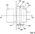
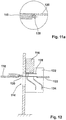
- FIGS. 7 to 12 a second embodiment of a freeze-drying plant according to the invention is shown, in which a loading bridge 120 is held on an underside of a door leaf 116.
- the door leaf 116 is made wider than in the first embodiment, so that the guide shafts 128 are arranged to the right and left of the feed opening 114.
- this second embodiment is analogous to that in the FIGS. 1 to 6 formed and also has right and left next to the door panel 116 provided guide elements 132, in the guide slot 134 at the loading bridge 120 mounted pins 136 extend.
- the stops 138 are mounted on the loading bridge 120 in the second embodiment and engage in not shown recesses on the adjusting plate 118 and the transfer table 122 a.
- FIGS. 7 to 12 Further details of this second embodiment can the FIGS. 7 to 12 be removed.
Landscapes
- Engineering & Computer Science (AREA)
- Mechanical Engineering (AREA)
- General Engineering & Computer Science (AREA)
- Health & Medical Sciences (AREA)
- Life Sciences & Earth Sciences (AREA)
- Molecular Biology (AREA)
- Drying Of Solid Materials (AREA)
- Freezing, Cooling And Drying Of Foods (AREA)
Description
- Die vorliegende Erfindung betrifft eine Übergabeeinheit zum Schaffen einer Transportverbindung zwischen einer Gefriergutzuführanlage und einer Gefriertrocknungsanlage gemäß dem Oberbegriff des Anspruches 1.
- Zum Beispiel aus der
EP 0 773 418 A1 , derUS5129162 A , derWO2013098834 A1 oder derFR 2 780 148 A1 - Bei dem Gefriergut handelt es sich um pharmazeutische Erzeugnisse, die hohen Hygieneanforderungen unterliegen, weshalb die Gefriergutzuführanlage so lange unter Reinraumbedingungen betrieben werden muss, bis das Gefriergut vorschriftsmäßig verpackt ist. Hierzu wird das Gefriergut während der Be- und Entladephasen mit einem reinen Fluid, zum Beispiel reiner Luft, Stickstoff oder einem anderen Gas überströmt.
- Außerdem wird das Innere der Druckkammer mit reinen Fluid, zum Beispiel reiner Luft, Stickstoff oder einem anderen Gas so stark beaufschlagt, dass an der Beschickungsöffnung ein vorgegebener Volumenstrom aus der Druckkammer austritt, um die Hygienevorschriften zu erfüllen.
- Bei manchen Gefriergutzuführanlagen ist die Beladebrücke schwenkbar angeordnet und kann nach dem Öffnen der Beschickungsöffnung in diese hineingeschwenkt werden, um an der Stellplatte zur Anlage zu kommen. Damit diese Schwenkbewegung ausgeführt werden kann, muss die Beschickungsöffnung entsprechend hoch ausgeführt sein mit der Folge, dass eine große Menge Fluid erforderlich ist, um an der Beschickungsöffnung die Hygienevorschriften zu erfüllen. Außerdem muss das Türblatt entsprechend stabil ausgelegt werden, um in geschlossenem Zustand den in der Druckkammer auftretenden Drücken standzuhalten.
- Bei anderen Gefriertrocknungsanlagen ist die Beladebrücke horizontal ausgerichtet und wird direkt durch die Beschickungsöffnung bis an die Stellplatte bewegt. In diesem Fall kann die Beschickungsöffnung niedriger, also kleiner ausgeführt werden, sodass auch das Türblatt sehr viel kleiner ausgeführt werden kann. Allerdings ist der Reinraum entsprechend groß anzulegen mit der Folge, dass hier mehr Fluid zur Sicherstellung der Reinraumbedingungen erforderlich ist. Außerdem erhöht sich hierdurch der Platzbedarf.
- Davon ausgehend liegt der vorliegenden Erfindung die Aufgabe zugrunde, eine Übergabeeinheit der eingangs genannten Art zu schaffen, so dass die Gefriertrocknungsanlage mit einer kleinen Beschickungsöffnung auskommt und so dass die Gefriergutzuführanlage kompakt ausgeführt werden kann.
- Als technische Lösung dieser Aufgabe wird erfindungsgemäß eine Übergabeeinheit der eingangs genannten Art mit den Merkmalen des Anspruches 1 vorgeschlagen. Vorteilhafte Weiterbildungen dieser Übergabeeinheit sind den Unteransprüchen zu entnehmen.
- Eine nach dieser technischen Lehre ausgebildete Übergabeeinheit hat den Vorteil, dass die Beladebrücke von der Gefriergutzuführanlage entkoppelt ist, mit der Folge, dass die Gefriergutzuführanlage entsprechend kleiner ausgeführt werden kann. Hierdurch ist der Platzbedarf vor der Gefriertrocknungsanlage entsprechend kleiner. Ein weiterer Vorteil besteht darin, dass der Aufwand zur Einhaltung der Hygienevorschriften entsprechend reduziert werdne kann, insbsondere dass weniger Fluid benötigt wird.
- Durch die bewegbare Anbringung der Beladebrücke direkt am Türblatt kann diese beim Bewegen des Türblattes teilweise durch die Beschickungsöffnung hindurch bis an die Stellplatte bewegt werden. Hierbei handelt es sich um eine Horizontalbewegung mit der Folge, dass die Beschickungsöffnung deutlich kleiner ausgeführt werden kann. Eine kleine Beschickungsöffnung hat den Vorteil, dass weniger Fluid zur Einhaltung der Hygienevorschriften benötigt wird, was die Betriebskosten der Gefriertrocknungsanlage deutlich reduziert. Auch kann hierbei das Türblatt entsprechend kleiner und damin kostengünstiger ausgelegt.
- In einer bevorzugten Ausführungsform wird das Türblatt über ein neben dem Türblatt angeordnetes Führungselement geführt. Dabei kann beispielsweise in dem Führungselement ein entsprechend der Bewegungsgeometrie ausgebildeter Führungsschlitz vorgesehen sein, in den ein an der Beladebrücke befestigter Stift eingreift. Hierdurch folgt die Beladebrücke im Verlauf des Führungsschlitzes und wird von ihrer Ruheposition außerhalb der Gefriertrocknungsanlage beim Bewegen des Türblattes teilweise durch die Beschickungsöffnung hindurch bis zur Stellplatte geführt und beim Schließen des Türblattes wird die Beladebrücke entsprechend wieder in ihre Ausgangsposition zurückgeführt.
- In einer bevorzugten Weiterbildung ist an der Beladebrücke mindestens ein, vorzugsweise vier, Linearlager angebracht während am Türblatt mindestens eine, vorzugsweise zwei, Führungswellen angebracht sind und wobei das Linearlager an der Führungswelle gehalten ist, sodass die Beladebrücke quer zum Türblatt verschiebbar ist. Hierdurch ist es in einfacher Weise möglich, die Beladebrücke von ihrer Ausgangsposition außerhalb der Gefriertrocknungsanlage horizontal durch die Beschickungsöffnung hindurch bis an die Stellplatte zu bewegen.
- In einer besonders bevorzugten Ausführungsform ist an der Stellplatte mindestens ein Anschlag zur Anlage der Beladebrücke vorgesehen. In ihrer endgültigen Position kommt dann die Beladebrücke auf diesem Anschlag zur Anlage. Dabei ist der Anschlag so ausgelegt, dass die Oberseite der Beladebrücke auf der Oberseite der Stellplatte fluchtet, sodass beim Transport des Gefrierguts keine störende Kante verbleibt.
- In einer vorteilhaften Weiterbildung umfasst der Anschlag eine Scheibe, welche mit einer exzentrisch angebrachten Schraube an einer Seitenfläche der Stellplatte gehalten ist. Durch die exzentrische Anordnung der Schraube kann die Scheibe so ausgerichtet werden, dass der Abstand der Oberkante der Scheibe zur Oberkante der Stellplatte exakt der Dicke der Beladebrücke entspricht, sodass beim Aufliegen der Beladebrücke am Anschlag ein sanfter Übergang von der Beladebrücke auf die Stellplatte erreicht wird.
- Der hier beschriebene Anschlag wird in analoger Weise auch an der Gefriergutzuführanlage angebracht, um auch dort einen sanften Übergang von der Gefriergutzuführanlage auf die Beladebrücke zu erreichen.
- In einer bevorzugten Ausführungsform ist die Beladebrücke aus einem federelastischen Material gebildet, vorzugsweise aus einem Edelstahlblech, mit einer Dicke von 2 mm. Eine solche Beladebrücke kann an einem an der Stellplatte vorgesehenen Anschlag aufgelegt und derart gehalten werden, dass die Beladebrücke unter Spannung steht. Dies kann dadurch erreicht werden, dass das Türblatt 1 bis 5 mm weiter bewegt wird, als eigentlich erforderlich. Eine derart vorgespannte Beladebrücke wird aufgrund der federelastischen Eigenschaften des Materials zuverlässig gegen den Anschlag gedrückt und gewährleistet somit einen exakten und auch vibrationsfreien Sitz an der Stellplatte, sodass das Gefriergut störungsfrei von der Beladebrücke auf die Stellplatte gelangen kann.
- In einer alternativen Ausführungsform ist zwischen dem Türblatt und der Beladebrücke mindestens ein Federelement vorgesehen, sodass die Beladebrücke federnd am Türblatt behalten ist. Dies hat den Vorteil, dass die Beladebrücke an der Stellplatte an einem Anschlag anliegt und durch die vorgespannte Feder zuverlässig in dieser Position gehalten wird. Eine derart vorgespannte Beladebrücke wird aufgrund der Feder zuverlässig gegen den Anschlag gedrückt und gewährleistet somit einen exakten und auch vibrationsfreien Sitz an der Stellplatte, sodass das Gefriergut störungsfrei von der Beladebrücke auf die Stellplatte gelangen kann.
- In einer anderen Ausführungsform ist es möglich, die Beladebrücke aus einem federelastischen Material mit dem Federelement zwischen der Beladebrücke und dem Türblatt zu kombinieren, um eine erhöhte Federwirkung zu erzeugen.
- Je nach Anwendungsfall kann die Beladebrücke oberhalb oder unterhalb des Türblattes angebracht sein.
- Weitere Vorteile der erfindungsgemäßen Gefriertrocknungsanlage ergeben sich aus der beigefügten Zeichnung und den nachstehend beschriebenen Ausführungsformen. Ebenso können die vorstehend genannten und die noch weiter ausgeführten Merkmale erfindungsgemäß jeweils einzeln oder in beliebigen Kombinationen miteinander verwendet werden. Die erwähnten Ausführungsformen sind nicht als abschließende Aufzählung zu verstehen, sondern haben vielmehr beispielhaften Charakter. Es zeigen:
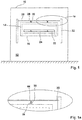
- Fig. 1
- eine Frontansicht in schematischer Darstellung einer ersten Ausführungsform eines Teiles einer erfindungsgemäßen Gefriertrocknungsanlage mit geschlossener Beschickungsöffnung;
- Fig. 1a
- eine Detailvergrößerung entlang Linie Ia in
Fig. 1 ; - Fig. 2
- eine schematische Darstellung einer Draufsicht auf einen Teil der Gefriertrocknungsanlage gemäß
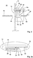
Fig. 1 ; - Fig. 3
- eine schematische Schnittdarstellung einer Seitenansicht der Gefriertrocknungsanlage gemäß
Fig. 1 , geschnitten entlang Linie III - III inFig. 2 bei verschlossener Beschickungsöffnung; - Fig. 3a
- eine Detailvergrößerung entlang Linie IIIa in
Fig. 3 ; - Fig. 4
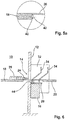
- eine schematische Schnittdarstellung einer Seitenansicht der Gefriertrocknungsanlage gemäß
Fig. 3 , bei teilweise geöffneter Beschickungsöffnung; - Fig. 5
- eine schematische Schnittdarstellung einer Seitenansicht der Gefriertrocknungsanlage gemäß
Fig. 3 , bei vollständig geöffneter Beschickungsöffnung und mit einem Teil einer vor der Gefriertrocknungsanlage angeordneten Gefriergutzuführanlage in schematischer Darstellung; - Fig. 5a
- eine Detailvergrößerung entlang Linie Va in
Fig. 5 ; - Fig. 6
- eine schematische Schnittdarstellung einer Seitenansicht der Gefriertrocknungsanlage gemäß
Fig. 3 bei vollständig geöffneter Beschickungsöffnung und mit einem Teil einer vor der Gefriertrocknungsanlage angeordneten Gefriergutzuführanlage in schematischer Darstellung während dem Transport von mit Gerfiergut gefüllten Vials; - Fig. 7
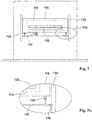
- eine Frontansicht einer schematischen Darstellung einer zweiten Ausführungsform einer erfindungsgemäßen Gefriertrocknungsanlage mit geschlossener Beschickungsöffnung;
- Fig. 7a
- eine Detailvergrößerung entlang Linie Vlla in
Fig. 7 ; - Fig. 8
- eine schematische Darstellung einer Draufsicht auf einen Teil der Gefriertrocknungsanlage gemäß
Fig. 7 ; - Fig. 9
- eine schematische Schnittdarstellung einer Seitenansicht der Gefriertrocknungsanlage gemäß
Fig. 7 , geschnitten entlang Linie IX - IX inFig. 8 bei verschlossener Beschickungsöffnung; - Fig. 9a
- eine Detailvergrößerung entlang Linie IXa in
Fig. 9 ; - Fig. 10
- eine schematische Schnittdarstellung einer Seitenansicht der Gefriertrocknungsanlage gemäß
Fig. 9 , bei teilweise geöffneter Beschickungsöffnung; - Fig. 11
- eine schematische Schnittdarstellung einer Seitenansicht der Gefriertrocknungsanlage gemäß
Fig. 9 bei vollständig geöffneter Beschickungsöffnung und mit einem Teil einer vor der Gefriertrocknungsanlage angeordneten Gefriergutzuführanlage in schematischer Darstellung; - Fig. 11a
- eine Detailvergrößerung entlang Linie XIa in
Fig. 11 ; - Fig. 12
- eine schematische Schnittdarstellung einer Seitenansicht der Gefriertrocknungsanlage gemäß
Fig. 9 bei vollständig geöffneter Beschickungsöffnung und mit einem Teil einer vor der Gefriertrocknungsanlage angeordneten Gefriergutzuführanlage in schematischer Darstellung während dem Transport von mit Gerfiergut gefüllten Vials. - In den
Figuren 1 bis 6 ist eine erste Ausführungsform einer erfindungsgemäßen Gefriertrocknungsanlage dargestellt. Diese Gefriertrocknungsanlage umfasst eine Druckkammer 10, an deren vorderseitiger Wand 12 eine Beschickungsöffnung 14 vorgesehen ist, welche über ein an der Wand 12 gehaltenes Türblatt 16 verschlossen werden kann. Innerhalb der Druckkammer 10 ist mindestens eine Stellplatte 18 zur Aufnahme von hier nicht näher dargestelltem Gefriergut vorgesehen. Diese Stellplatte 18 befindet sich auf Höhe der Beschickungsöffnung 14 und korrespondiert mit einer hier nicht näher dargestellten Gefriergutzuführanlage, welche vor der Gefriertrocknungsanlage angeordnet ist. - An einer Oberseite des Türblattes 16 ist eine Beladebrücke 20 gehalten, welche während der Beladung der Gefriertrocknungsanlage mit Gefriergut bündig zwischen der Stellplatte 18 und einem Übergabetisch 22 der Gefriergutzuführanlage angeordnet ist, wie dies in
Fig. 6 dargestellt ist. In dieser Position kann dann ein zur Gefriergutzuführanlage gehörende Schieber 24 eine Anzahl von mit Gefriergut gefülltem Vials 26 vom Übergabetisch 22 über die Beladebrücke 20 auf die Stellplatte 18 schieben. - An einer Oberseite des Türblattes 16 sind zwei Führungswellen 28 in Form je einer Stange angebracht, welche quer zum Türblatt 16 ausgerichtet sind. An einer Unterseite der Beladebrücke 20 sind korrespondierend zu den Führungswellen 28 zwei Linearlager 30 angebracht, wobei die Linearlager 30 derart an den Führungswellen 28 gehalten sind, sodass die Beladebrücke 20 quer zum Türblatt 16 verschiebbar ist.
- Rechts und links neben dem Türblatt 16 ist je ein vertikal ausgerichtetes Führungselement 32 angebracht, wobei in jedem Führungselement 32 zwei parallel angeordnete Führungsschlitze 34 vorgesehen sind, in die je ein an der Beladebrücke 20 befestigter Stift 36 hineinragt. Dabei ist der Führungsschlitz 34 derart geschwungen ausgerichtet, dass die Beladebrücke beim Herunterfahren des Türblattes 16 von einer Ausgangsposition außerhalb der Gefriertrocknungsanlage teilweise in die Beschickungsöffnung 14 hindurchgeführt und bis an die Stellplatte 18 herangeführt wird, sodass in der Endstellung die Beladebrücke 20 eine Verbindung zwischen der Stellplatte 18 und dem Übergabetisch 22 der Gefriergutzuführanlage herstellt, wie dies in den
Figuren 3 bis 6 schematisch dargestellt ist. In dieser Endstellung kann dann ein Schieber 24 die mit Gefriergut gefüllten Vials 26 von dem Übergabetisch 22 über die Beladebrücke 20 bis zur Stellplatte 18 schieben oder in umgekehrter Richtung die Stellplatte 18 entsprechend entladen. - Zum Verschließen der Beschickungsöffnung 14 wird das Türblatt 16 nach oben bewegt, wobei die Beladebrücke 20 aus ihrer Endstellung heraus mittels der Führungsschlitze 34 durch die Beschickungsöffnung 14 nach außerhalb der Gefriertrocknungsanlage bewegt wird, sodass die Beladebrücke 20 bei geschlossenem Türblatt 16 vollständig außerhalb der Gefriertrocknungsanlage angeordnet ist.
- Damit die Beladebrücke 20 während dem Be- und Entladen der Stellplatte 18 präzise, zuverlässig und vibrationsarm an der Stellplatte 18 anliegt, sind an der Stellplatte 18 drei Anschläge 38 vorgesehen. Jeder Anschlag 38 umfasst eine kreisrunde Scheibe 40, welche mit einer exentrisch angebrachten Schraube 42 an einer Seitenwand der Stellplatte 18 angeschraubt ist. Aufgrund der exzentrischen Anbringung der Scheibe 40 kann hiermit der Abstand zwischen einer Oberkante der Scheibe 40 und einer Oberkante der Stellplatte 18 so eingestellt werden, dass die auf der Scheibe 40 aufliegende Beladebrücke 20 mit ihrer Oberkante exakt mit der Oberkante der Stellplatte 18 fluchtet, sodass ein kantenfreier Übergang erreicht wird. Solche Anschläge 38 ist auch am Übergabetisch 22 vorgesehen, um auch hier einen zuverlässigen, präzisen und vibrationsarmen Übergang von der Beladebrücke 20 auf den Übergabetisch 22 zu erreichen.
- In der hier dargestellten Ausführungsform ist die Beladebrücke 20 aus einem 2 mm Edelstahlblech gebildet, sodass die Beladebrücke 20 federelastische Eigenschaften aufweist. Darüber hinaus ist zwischen jedem Linearlager 30 und der Beladebrücke 20 ein Federelement 44 vorgesehen, sodass die Beladebrücke 20 federnd am Türblatt 16 gehalten ist. Ist nun die Beladebrücke 20 in ihrer Endstellung, wobei das Türblatt 16 die Beschickungsöffnung 14 entsprechend freigibt, so kann das Türblatt 16 um weitere 1 mm bis 5 mm, vorzugsweise 2 mm abgesenkt werden, um sowohl das Federelement 44, als auch die federelastische Beladebrücke 20 zu spannen. In dieser Position übt das Federelement 44 genauso wie die vorgespannte Beladebrücke 20 eine Federkraft auf die Beladebrücke 20 aus und hält somit die Beladebrücke 20 zuverlässig und vibrationsarm am Anschlag 38, sodass beim Be- oder Entladen der Stellplatte 18 das in den Vials 26 befindliche Gefriergut die Übergänge zwischen der Stellplatte 18 und der Beladebrücke 20 einerseits bzw. der Beladebrücke 20 und dem Übergabetisch 22 störungsfrei passieren kann.
- In einer anderen, hier nicht dargestellten Ausführungsform, wird auf das Federelement verzichtet, sodass lediglich die federelastischen Materialeigenschaften der Beladebrücke die hier gewünschte Federkraft ausüben.
- In noch einer anderen, hier nicht dargestellten Ausführungsform ist die Beladebrücke aus einem anderen, nicht ausreichend federelastischem Material gebildet, während unter der Beladebrücke die Federelemente vorgesehen sind, um eine Vorspannung auf die Beladebrücke auszuüben.
- In den
Figuren 7 bis 12 ist eine zweite Ausführungsform einer erfindungsgemäßen Gefriertrocknungsanlage abgebildet, bei der eine Beladebrücke 120 an einer Unterseite eines Türblattes 116 gehalten ist. Dabei ist das Türblatt 116 breiter ausgeführt als bei der ersten Ausführungsform, sodass die Führungswellen 128 rechts und links neben der Beschickungsöffnung 114 angeordnet sind. Im Übrigen ist diese zweite Ausführungsform analog zu der in denFiguren 1 bis 6 beschriebenen ersten Ausführungsform ausgebildet und besitzt ebenfalls rechts und links neben dem Türblatt 116 vorgesehene Führungselemente 132, in deren Führungsschlitz 134 an der Beladebrücke 120 angebrachte Stifte 136 hineinreichen. - Im Gegensatz zur ersten Ausführungsform sind in der zweiten Ausführungsform die Anschläge 138 an der Beladebrücke 120 angebracht und greifen in nicht näher dargestellte Aussparungen an der Stellplatte 118 bzw. am Übergabetisch 122 ein.
- Weitere Einzelheiten zu dieser zweiten Ausführungsform können den
Figuren 7 bis 12 entnommen werden.
Claims (9)
- Gefriertrocknungsanlage mit einer Druckkammer (10), mindestens einer in der Druckkammer (10) angeordneten Stellplatte (18, 118) zur Aufnahme von Gefriergut und einer Übergabeeinheit zum Schaffen einer Transportverbindung zwischen der Gefriertrocknungsanlage und einer separaten Gefriergutzuführanlage, wobei die Druckkammer (10) eine Wand (12) und eine in der Wand (12) angeordnete Beschickungsöffnung (14, 114), sowie ein an der Wand (12) gehaltenes Türblatt (16, 116) zum Verschließen der Beschickungsöffnung (14, 114) aufweist, dadurch gekennzeichnet,
dass am Türblatt (16, 116) eine Beladebrücke (20, 120) vorgesehen ist, wobei die Beladebrücke (20, 120) verschiebbar am Türblatt (16, 116) gehalten ist, wobei die Beladebrücke (20, 120) bei geschlossener Beschickungsöffnung (14, 114) außerhalb der Druckkammer (10) angeordnet ist und wobei die Beladebrücke (20, 120) teilweise durch die Beschickungsöffnung (14, 114) hindurch bis an die Stellplatte (18, 118) verschiebbar ist und in dieser Position eine Transportverbindung zwischen der Stellplatte (18, 118) und einem Übergabetisch (22, 122) der Gefriergutzuführanlage schafft, so dass Gefriergut durch die Beschickungsöffnung (14, 114) bis zur Stellplatte (18, 118) transportiert werden kann. - Gefriertrocknungsanlage nach Anspruch 1,
dadurch gekennzeichnet,
dass die Beladebrücke (20, 120) über mindestens ein neben dem Türblatt (16, 116) angeordnetes Führungselement (32, 132) geführt wird. - Gefriertrocknungsanlage nach Anspruch 2,
dadurch gekennzeichnet,
dass das Führungselement (32, 132) einen Führungsschlitz (34, 134) aufweist, in den ein an der Beladebrücke (20, 120) befestigter Stift (36, 136) eingreift, um die Beladebrücke (20, 120) entsprechend des Verlaufes des Führungsschlitzes (34, 134) zu bewegen. - Gefriertrocknungsanlage nach einem der vorangehenden Ansprüche,
dadurch gekennzeichnet,
dass an der Beladebrücke (20, 120) mindestens ein Linearlager (30) angebracht ist, welches in eine am Türblatt (16, 116) angebrachte Führungswelle (28, 128) derart eingreift, dass die Beladebrücke (20, 120) quer zum Türblatt (16, 116) verschiebbar ist. - Gefriertrocknungsanlage nach einem der vorangehenden Ansprüche,
dadurch gekennzeichnet,
dass an der Stellplatte (18, 118) mindestens ein Anschlag (38, 138) zur Anlage der Beladebrücke (20, 120) derart vorgesehen ist, dass eine Oberseite der Beladebrücke (20, 120) mit einer Oberseite der Stellplatte (18, 118) fluchtet. - Gefriertrocknungsanlage nach Anspruch 5,
dadurch gekennzeichnet,
dass der Anschlag (38, 138) eine Scheibe (40) umfasst, die mit einer exzentrisch angebrachten Schraube (42) an einer Seitenfläche der Stellplatte (18) oder der Beladebrücke (120) gehalten ist. - Gefriertrocknungsanlage nach einem der vorangehenden Ansprüche,
dadurch gekennzeichnet,
dass die Beladebrücke (20, 120) aus einem federelastischen Material gebildet ist, insbesondere aus einem Edelstahlblech mit einer Dicke zwischen 1 mm und 3 mm, vorzugsweise 2 mm. - Gefriertrocknungsanlage nach einem der vorangehenden Ansprüche,
dadurch gekennzeichnet,
dass zwischen dem Türblatt (16, 116) und der Beladebrücke (20, 120) mindestens ein Federelement (44) vorgesehen ist, sodass die Beladebrücke (20, 120) federnd am Türblatt (16, 116) gehalten ist. - Gefriertrocknungsanlage nach einem der vorangehenden Ansprüche,
dadurch gekennzeichnet,
dass die Beladebrücke (20, 120) an einer Oberseite oder an einer Unterseite des Türblattes (16, 116) gehalten ist.
Applications Claiming Priority (1)
| Application Number | Priority Date | Filing Date | Title |
|---|---|---|---|
| DE102015009866.7A DE102015009866B4 (de) | 2015-08-03 | 2015-08-03 | Übergabeeinheit zum Schaffen einer Transportverbindung zwischen einer Gefriergutzuführanlage und einer Gefriertrocknungsanlage |
Publications (2)
| Publication Number | Publication Date |
|---|---|
| EP3136031A1 EP3136031A1 (de) | 2017-03-01 |
| EP3136031B1 true EP3136031B1 (de) | 2019-04-17 |
Family
ID=56413482
Family Applications (1)
| Application Number | Title | Priority Date | Filing Date |
|---|---|---|---|
| EP16178380.8A Not-in-force EP3136031B1 (de) | 2015-08-03 | 2016-07-07 | Gefriertrocknungsanlage umfassend eine übergabeeinheit |
Country Status (3)
| Country | Link |
|---|---|
| EP (1) | EP3136031B1 (de) |
| DE (1) | DE102015009866B4 (de) |
| ES (1) | ES2731892T3 (de) |
Families Citing this family (2)
| Publication number | Priority date | Publication date | Assignee | Title |
|---|---|---|---|---|
| DE102020118727A1 (de) | 2020-07-15 | 2022-01-20 | Groninger & Co. Gmbh | Trägerplatte, Beladungssystem und Gefriertrocknungssystem |
| DE102020118726A1 (de) | 2020-07-15 | 2022-01-20 | Groninger & Co. Gmbh | Ladesystem für einen Gefriertrockner, Gefriertrocknungssystem, und entsprechendes Verfahren |
Family Cites Families (12)
| Publication number | Priority date | Publication date | Assignee | Title |
|---|---|---|---|---|
| IT8222194U1 (it) * | 1982-06-18 | 1983-12-18 | Edwards Alto Vuoto Spa | Dispositivo per il caricamento delle piastre porta-prodotto di una camera di liofilizzazione mediante impiego di contenitori preposizionati ad altezza costante. |
| DE9001612U1 (de) * | 1989-04-07 | 1990-04-19 | Finn-Aqua Santasalo-Sohlberg GmbH, 50354 Hürth | Vorrichtung zum Beschicken und Entladen einer Gefriertrocknungseinrichtung |
| DE19541947C1 (de) * | 1995-11-10 | 1997-08-07 | Hof Hans Georg | Tür für Autoklaven, autoklavierbare Gefriertrocknungsanlagen, Gefriertrocknungsanlagen etc. |
| JPH10977A (ja) * | 1996-06-13 | 1998-01-06 | Nissan Diesel Motor Co Ltd | テールゲートリフタ装置 |
| DE19823167A1 (de) * | 1998-05-23 | 1999-12-02 | Alexander Wagner | Be-Entladevorrichtung zur Be-/Entladung auf eine horizontal schwingungsfähig angeordnete Stellfläche für Behandlungsanlagen von Behältnissen oder Stückgütern |
| FR2780148B1 (fr) * | 1998-06-18 | 2000-08-18 | Usifroid | Procede de chargement et dechargement sans fond pour cuve de lyophilisation, et dispositif pour sa mise en oeuvre |
| DE102005017140A1 (de) * | 2005-04-13 | 2006-10-19 | Steris Gmbh | Verfahren zum Betrieb von Gefriertrocknungsanlagen mit einer Kammer und mit Be- und Entladeeinrichtungen sowie dafür geeignet ausgebildete Anlagen dieser Art |
| WO2007131760A1 (en) * | 2006-05-12 | 2007-11-22 | Ima Life S.R.L. | Loading system for a freeze dryer |
| DE102008020705A1 (de) * | 2008-04-24 | 2009-10-29 | Gea Lyophil Gmbh | Be- und Entladevorrichtung für eine Produktbehandlungseinrichtung |
| DE102008064094A1 (de) * | 2008-12-19 | 2010-07-01 | Accurro Gmbh | Gefriertrocknungsanlage und Vorrichtung zum Be- und Entladen einer Stellplatte einer Gefriertrocknungsanlage |
| WO2013098834A1 (en) * | 2011-09-21 | 2013-07-04 | Janak Shanghvi | Loading apparatus for a freeze dryer |
| CN204279881U (zh) * | 2014-10-16 | 2015-04-22 | 重庆帆洪船舶机械有限公司 | 一种带有卸沙机构的沙舱 |
-
2015
- 2015-08-03 DE DE102015009866.7A patent/DE102015009866B4/de not_active Expired - Fee Related
-
2016
- 2016-07-07 ES ES16178380T patent/ES2731892T3/es active Active
- 2016-07-07 EP EP16178380.8A patent/EP3136031B1/de not_active Not-in-force
Non-Patent Citations (1)
| Title |
|---|
| None * |
Also Published As
| Publication number | Publication date |
|---|---|
| DE102015009866B4 (de) | 2020-11-26 |
| DE102015009866A1 (de) | 2017-02-09 |
| ES2731892T3 (es) | 2019-11-19 |
| EP3136031A1 (de) | 2017-03-01 |
Similar Documents
| Publication | Publication Date | Title |
|---|---|---|
| DE3405787C2 (de) | Klebeband-Verschlußmaschine für Faltbehälter | |
| EP2816305B1 (de) | Vorrichtung zum Be- und Entladen einer Stellplatte einer Gefriertrocknungsanlage und ein Verfahren hierfür | |
| DE19547049A1 (de) | Auszugsperre für übereinander angeordnete Schubladen | |
| EP2649261B1 (de) | SCHLIEß- UND DÄMPFUNGSVORRICHTUNG FÜR BEWEGBARE MÖBELTEILE | |
| EP3960657B1 (de) | Stapellageranordnung | |
| EP3358989B1 (de) | Bewegungseinrichtung für schubladen | |
| DE1947493U (de) | Betaetigungsvorrichtung fuer aerosolbehaelter. | |
| DE2618439B1 (de) | Transporteinrichtung fuer die auswertung von identifizierungskarten | |
| WO2005032940A1 (de) | System zum be- und entladen eines laderaums, insbesondere des flugzeugs, mit stückgut | |
| DE29620152U1 (de) | Zentralverriegelung für Möbel | |
| CH687836A5 (de) | Windschutz fur eine Waage. | |
| DE3305652A1 (de) | Automatisches kuelbel- oder rohlingskolben-zufuehrungssystem | |
| EP3136031A1 (de) | Übergabeeinheit zum schaffen einer transportverbindung zwischen einer gefriergutzuführanlage und einer gefriertrocknungsanlage | |
| DE20205395U1 (de) | Sortieranlage für Stückgut | |
| EP3524488A1 (de) | Auslassvorrichtung zum regeln der lichten weite einer auslassöffnung eines zur schwerkraft-entladung durch diese auslassvorrichtung eingerichteten schüttgut-transportsilos | |
| WO2019096464A1 (de) | Warenzwischenlagervorrichtung | |
| EP3042867B1 (de) | Bediengerät für eine Kommissioniervorrichtung | |
| DE4413475A1 (de) | Vorrichtung zum Trennen von auf Rollenbahnen beförderten Paletten | |
| DE10124684C1 (de) | Ausziehsperre für Schubladen | |
| DE20015168U1 (de) | Messerhalter mit Stoßabsorber für eine Einrichtung zum Längsteilen einer Materialbahn | |
| DE3720001C2 (de) | ||
| EP0277323A1 (de) | Schiebeventil | |
| EP3741264A1 (de) | Vorrichtung zum vorschub von waren | |
| DE2520428A1 (de) | Als endlos-kettenstabband ausgebildete vorschubeinrichtung fuer verpackungsgueter | |
| DE3631139A1 (de) | Bremsvorrichtung fuer durchlaufregal-rollenleisten |
Legal Events
| Date | Code | Title | Description |
|---|---|---|---|
| PUAI | Public reference made under article 153(3) epc to a published international application that has entered the european phase |
Free format text: ORIGINAL CODE: 0009012 |
|
| STAA | Information on the status of an ep patent application or granted ep patent |
Free format text: STATUS: THE APPLICATION HAS BEEN PUBLISHED |
|
| AK | Designated contracting states |
Kind code of ref document: A1 Designated state(s): AL AT BE BG CH CY CZ DE DK EE ES FI FR GB GR HR HU IE IS IT LI LT LU LV MC MK MT NL NO PL PT RO RS SE SI SK SM TR |
|
| AX | Request for extension of the european patent |
Extension state: BA ME |
|
| STAA | Information on the status of an ep patent application or granted ep patent |
Free format text: STATUS: REQUEST FOR EXAMINATION WAS MADE |
|
| 17P | Request for examination filed |
Effective date: 20170310 |
|
| RBV | Designated contracting states (corrected) |
Designated state(s): AL AT BE BG CH CY CZ DE DK EE ES FI FR GB GR HR HU IE IS IT LI LT LU LV MC MK MT NL NO PL PT RO RS SE SI SK SM TR |
|
| STAA | Information on the status of an ep patent application or granted ep patent |
Free format text: STATUS: EXAMINATION IS IN PROGRESS |
|
| 17Q | First examination report despatched |
Effective date: 20171024 |
|
| GRAP | Despatch of communication of intention to grant a patent |
Free format text: ORIGINAL CODE: EPIDOSNIGR1 |
|
| STAA | Information on the status of an ep patent application or granted ep patent |
Free format text: STATUS: GRANT OF PATENT IS INTENDED |
|
| INTG | Intention to grant announced |
Effective date: 20181116 |
|
| GRAS | Grant fee paid |
Free format text: ORIGINAL CODE: EPIDOSNIGR3 |
|
| GRAA | (expected) grant |
Free format text: ORIGINAL CODE: 0009210 |
|
| STAA | Information on the status of an ep patent application or granted ep patent |
Free format text: STATUS: THE PATENT HAS BEEN GRANTED |
|
| AK | Designated contracting states |
Kind code of ref document: B1 Designated state(s): AL AT BE BG CH CY CZ DE DK EE ES FI FR GB GR HR HU IE IS IT LI LT LU LV MC MK MT NL NO PL PT RO RS SE SI SK SM TR |
|
| REG | Reference to a national code |
Ref country code: GB Ref legal event code: FG4D Free format text: NOT ENGLISH |
|
| REG | Reference to a national code |
Ref country code: CH Ref legal event code: EP |
|
| REG | Reference to a national code |
Ref country code: DE Ref legal event code: R096 Ref document number: 502016004202 Country of ref document: DE |
|
| REG | Reference to a national code |
Ref country code: AT Ref legal event code: REF Ref document number: 1122008 Country of ref document: AT Kind code of ref document: T Effective date: 20190515 Ref country code: IE Ref legal event code: FG4D Free format text: LANGUAGE OF EP DOCUMENT: GERMAN |
|
| REG | Reference to a national code |
Ref country code: NL Ref legal event code: FP |
|
| REG | Reference to a national code |
Ref country code: LT Ref legal event code: MG4D |
|
| PG25 | Lapsed in a contracting state [announced via postgrant information from national office to epo] |
Ref country code: NO Free format text: LAPSE BECAUSE OF FAILURE TO SUBMIT A TRANSLATION OF THE DESCRIPTION OR TO PAY THE FEE WITHIN THE PRESCRIBED TIME-LIMIT Effective date: 20190717 Ref country code: PT Free format text: LAPSE BECAUSE OF FAILURE TO SUBMIT A TRANSLATION OF THE DESCRIPTION OR TO PAY THE FEE WITHIN THE PRESCRIBED TIME-LIMIT Effective date: 20190817 Ref country code: AL Free format text: LAPSE BECAUSE OF FAILURE TO SUBMIT A TRANSLATION OF THE DESCRIPTION OR TO PAY THE FEE WITHIN THE PRESCRIBED TIME-LIMIT Effective date: 20190417 Ref country code: FI Free format text: LAPSE BECAUSE OF FAILURE TO SUBMIT A TRANSLATION OF THE DESCRIPTION OR TO PAY THE FEE WITHIN THE PRESCRIBED TIME-LIMIT Effective date: 20190417 Ref country code: LT Free format text: LAPSE BECAUSE OF FAILURE TO SUBMIT A TRANSLATION OF THE DESCRIPTION OR TO PAY THE FEE WITHIN THE PRESCRIBED TIME-LIMIT Effective date: 20190417 Ref country code: HR Free format text: LAPSE BECAUSE OF FAILURE TO SUBMIT A TRANSLATION OF THE DESCRIPTION OR TO PAY THE FEE WITHIN THE PRESCRIBED TIME-LIMIT Effective date: 20190417 Ref country code: SE Free format text: LAPSE BECAUSE OF FAILURE TO SUBMIT A TRANSLATION OF THE DESCRIPTION OR TO PAY THE FEE WITHIN THE PRESCRIBED TIME-LIMIT Effective date: 20190417 |
|
| REG | Reference to a national code |
Ref country code: ES Ref legal event code: FG2A Ref document number: 2731892 Country of ref document: ES Kind code of ref document: T3 Effective date: 20191119 |
|
| PG25 | Lapsed in a contracting state [announced via postgrant information from national office to epo] |
Ref country code: BG Free format text: LAPSE BECAUSE OF FAILURE TO SUBMIT A TRANSLATION OF THE DESCRIPTION OR TO PAY THE FEE WITHIN THE PRESCRIBED TIME-LIMIT Effective date: 20190717 Ref country code: RS Free format text: LAPSE BECAUSE OF FAILURE TO SUBMIT A TRANSLATION OF THE DESCRIPTION OR TO PAY THE FEE WITHIN THE PRESCRIBED TIME-LIMIT Effective date: 20190417 Ref country code: LV Free format text: LAPSE BECAUSE OF FAILURE TO SUBMIT A TRANSLATION OF THE DESCRIPTION OR TO PAY THE FEE WITHIN THE PRESCRIBED TIME-LIMIT Effective date: 20190417 Ref country code: PL Free format text: LAPSE BECAUSE OF FAILURE TO SUBMIT A TRANSLATION OF THE DESCRIPTION OR TO PAY THE FEE WITHIN THE PRESCRIBED TIME-LIMIT Effective date: 20190417 Ref country code: GR Free format text: LAPSE BECAUSE OF FAILURE TO SUBMIT A TRANSLATION OF THE DESCRIPTION OR TO PAY THE FEE WITHIN THE PRESCRIBED TIME-LIMIT Effective date: 20190718 |
|
| PG25 | Lapsed in a contracting state [announced via postgrant information from national office to epo] |
Ref country code: IS Free format text: LAPSE BECAUSE OF FAILURE TO SUBMIT A TRANSLATION OF THE DESCRIPTION OR TO PAY THE FEE WITHIN THE PRESCRIBED TIME-LIMIT Effective date: 20190817 |
|
| REG | Reference to a national code |
Ref country code: DE Ref legal event code: R097 Ref document number: 502016004202 Country of ref document: DE |
|
| PG25 | Lapsed in a contracting state [announced via postgrant information from national office to epo] |
Ref country code: SK Free format text: LAPSE BECAUSE OF FAILURE TO SUBMIT A TRANSLATION OF THE DESCRIPTION OR TO PAY THE FEE WITHIN THE PRESCRIBED TIME-LIMIT Effective date: 20190417 Ref country code: CZ Free format text: LAPSE BECAUSE OF FAILURE TO SUBMIT A TRANSLATION OF THE DESCRIPTION OR TO PAY THE FEE WITHIN THE PRESCRIBED TIME-LIMIT Effective date: 20190417 Ref country code: RO Free format text: LAPSE BECAUSE OF FAILURE TO SUBMIT A TRANSLATION OF THE DESCRIPTION OR TO PAY THE FEE WITHIN THE PRESCRIBED TIME-LIMIT Effective date: 20190417 Ref country code: EE Free format text: LAPSE BECAUSE OF FAILURE TO SUBMIT A TRANSLATION OF THE DESCRIPTION OR TO PAY THE FEE WITHIN THE PRESCRIBED TIME-LIMIT Effective date: 20190417 Ref country code: DK Free format text: LAPSE BECAUSE OF FAILURE TO SUBMIT A TRANSLATION OF THE DESCRIPTION OR TO PAY THE FEE WITHIN THE PRESCRIBED TIME-LIMIT Effective date: 20190417 |
|
| PLBE | No opposition filed within time limit |
Free format text: ORIGINAL CODE: 0009261 |
|
| STAA | Information on the status of an ep patent application or granted ep patent |
Free format text: STATUS: NO OPPOSITION FILED WITHIN TIME LIMIT |
|
| PG25 | Lapsed in a contracting state [announced via postgrant information from national office to epo] |
Ref country code: MC Free format text: LAPSE BECAUSE OF FAILURE TO SUBMIT A TRANSLATION OF THE DESCRIPTION OR TO PAY THE FEE WITHIN THE PRESCRIBED TIME-LIMIT Effective date: 20190417 Ref country code: SM Free format text: LAPSE BECAUSE OF FAILURE TO SUBMIT A TRANSLATION OF THE DESCRIPTION OR TO PAY THE FEE WITHIN THE PRESCRIBED TIME-LIMIT Effective date: 20190417 |
|
| 26N | No opposition filed |
Effective date: 20200120 |
|
| PG25 | Lapsed in a contracting state [announced via postgrant information from national office to epo] |
Ref country code: TR Free format text: LAPSE BECAUSE OF FAILURE TO SUBMIT A TRANSLATION OF THE DESCRIPTION OR TO PAY THE FEE WITHIN THE PRESCRIBED TIME-LIMIT Effective date: 20190417 |
|
| PG25 | Lapsed in a contracting state [announced via postgrant information from national office to epo] |
Ref country code: LU Free format text: LAPSE BECAUSE OF NON-PAYMENT OF DUE FEES Effective date: 20190707 Ref country code: SI Free format text: LAPSE BECAUSE OF FAILURE TO SUBMIT A TRANSLATION OF THE DESCRIPTION OR TO PAY THE FEE WITHIN THE PRESCRIBED TIME-LIMIT Effective date: 20190417 |
|
| PG25 | Lapsed in a contracting state [announced via postgrant information from national office to epo] |
Ref country code: IE Free format text: LAPSE BECAUSE OF NON-PAYMENT OF DUE FEES Effective date: 20190707 |
|
| PG25 | Lapsed in a contracting state [announced via postgrant information from national office to epo] |
Ref country code: CY Free format text: LAPSE BECAUSE OF FAILURE TO SUBMIT A TRANSLATION OF THE DESCRIPTION OR TO PAY THE FEE WITHIN THE PRESCRIBED TIME-LIMIT Effective date: 20190417 |
|
| PG25 | Lapsed in a contracting state [announced via postgrant information from national office to epo] |
Ref country code: HU Free format text: LAPSE BECAUSE OF FAILURE TO SUBMIT A TRANSLATION OF THE DESCRIPTION OR TO PAY THE FEE WITHIN THE PRESCRIBED TIME-LIMIT; INVALID AB INITIO Effective date: 20160707 Ref country code: MT Free format text: LAPSE BECAUSE OF FAILURE TO SUBMIT A TRANSLATION OF THE DESCRIPTION OR TO PAY THE FEE WITHIN THE PRESCRIBED TIME-LIMIT Effective date: 20190417 |
|
| PGFP | Annual fee paid to national office [announced via postgrant information from national office to epo] |
Ref country code: NL Payment date: 20210721 Year of fee payment: 6 |
|
| PGFP | Annual fee paid to national office [announced via postgrant information from national office to epo] |
Ref country code: IT Payment date: 20210727 Year of fee payment: 6 Ref country code: FR Payment date: 20210729 Year of fee payment: 6 Ref country code: AT Payment date: 20210722 Year of fee payment: 6 |
|
| PGFP | Annual fee paid to national office [announced via postgrant information from national office to epo] |
Ref country code: ES Payment date: 20210928 Year of fee payment: 6 Ref country code: CH Payment date: 20210721 Year of fee payment: 6 Ref country code: BE Payment date: 20210721 Year of fee payment: 6 Ref country code: GB Payment date: 20210722 Year of fee payment: 6 |
|
| PG25 | Lapsed in a contracting state [announced via postgrant information from national office to epo] |
Ref country code: MK Free format text: LAPSE BECAUSE OF FAILURE TO SUBMIT A TRANSLATION OF THE DESCRIPTION OR TO PAY THE FEE WITHIN THE PRESCRIBED TIME-LIMIT Effective date: 20190417 |
|
| REG | Reference to a national code |
Ref country code: CH Ref legal event code: PL |
|
| REG | Reference to a national code |
Ref country code: NL Ref legal event code: MM Effective date: 20220801 |
|
| REG | Reference to a national code |
Ref country code: AT Ref legal event code: MM01 Ref document number: 1122008 Country of ref document: AT Kind code of ref document: T Effective date: 20220707 |
|
| GBPC | Gb: european patent ceased through non-payment of renewal fee |
Effective date: 20220707 |
|
| REG | Reference to a national code |
Ref country code: BE Ref legal event code: MM Effective date: 20220731 |
|
| PG25 | Lapsed in a contracting state [announced via postgrant information from national office to epo] |
Ref country code: LI Free format text: LAPSE BECAUSE OF NON-PAYMENT OF DUE FEES Effective date: 20220731 Ref country code: FR Free format text: LAPSE BECAUSE OF NON-PAYMENT OF DUE FEES Effective date: 20220731 Ref country code: CH Free format text: LAPSE BECAUSE OF NON-PAYMENT OF DUE FEES Effective date: 20220731 Ref country code: AT Free format text: LAPSE BECAUSE OF NON-PAYMENT OF DUE FEES Effective date: 20220707 |
|
| PG25 | Lapsed in a contracting state [announced via postgrant information from national office to epo] |
Ref country code: GB Free format text: LAPSE BECAUSE OF NON-PAYMENT OF DUE FEES Effective date: 20220707 Ref country code: BE Free format text: LAPSE BECAUSE OF NON-PAYMENT OF DUE FEES Effective date: 20220731 |
|
| PG25 | Lapsed in a contracting state [announced via postgrant information from national office to epo] |
Ref country code: NL Free format text: LAPSE BECAUSE OF NON-PAYMENT OF DUE FEES Effective date: 20220801 |
|
| PG25 | Lapsed in a contracting state [announced via postgrant information from national office to epo] |
Ref country code: IT Free format text: LAPSE BECAUSE OF NON-PAYMENT OF DUE FEES Effective date: 20220707 |
|
| REG | Reference to a national code |
Ref country code: ES Ref legal event code: FD2A Effective date: 20230825 |
|
| PG25 | Lapsed in a contracting state [announced via postgrant information from national office to epo] |
Ref country code: ES Free format text: LAPSE BECAUSE OF NON-PAYMENT OF DUE FEES Effective date: 20220708 |
|
| PGFP | Annual fee paid to national office [announced via postgrant information from national office to epo] |
Ref country code: DE Payment date: 20230617 Year of fee payment: 8 |
|
| REG | Reference to a national code |
Ref country code: DE Ref legal event code: R119 Ref document number: 502016004202 Country of ref document: DE |
|
| PG25 | Lapsed in a contracting state [announced via postgrant information from national office to epo] |
Ref country code: DE Free format text: LAPSE BECAUSE OF NON-PAYMENT OF DUE FEES Effective date: 20250201 |