EP3136020A1 - Système de réfrigération par compression à deux étages - Google Patents
Système de réfrigération par compression à deux étages Download PDFInfo
- Publication number
- EP3136020A1 EP3136020A1 EP16185537.4A EP16185537A EP3136020A1 EP 3136020 A1 EP3136020 A1 EP 3136020A1 EP 16185537 A EP16185537 A EP 16185537A EP 3136020 A1 EP3136020 A1 EP 3136020A1
- Authority
- EP
- European Patent Office
- Prior art keywords
- stage compressor
- oil
- gas
- closed housing
- low
- Prior art date
- Legal status (The legal status is an assumption and is not a legal conclusion. Google has not performed a legal analysis and makes no representation as to the accuracy of the status listed.)
- Granted
Links
- 230000006835 compression Effects 0.000 title claims abstract description 30
- 238000007906 compression Methods 0.000 title claims abstract description 30
- 238000005057 refrigeration Methods 0.000 title claims abstract description 27
- 239000003507 refrigerant Substances 0.000 claims abstract description 129
- 238000002347 injection Methods 0.000 claims abstract description 43
- 239000007924 injection Substances 0.000 claims abstract description 43
- 239000007788 liquid Substances 0.000 claims abstract description 28
- 238000007599 discharging Methods 0.000 claims description 4
- 238000004891 communication Methods 0.000 claims description 3
- 239000003921 oil Substances 0.000 description 151
- 230000015556 catabolic process Effects 0.000 description 22
- 238000006731 degradation reaction Methods 0.000 description 22
- 238000010438 heat treatment Methods 0.000 description 18
- 230000006837 decompression Effects 0.000 description 10
- 238000013021 overheating Methods 0.000 description 10
- 230000005855 radiation Effects 0.000 description 10
- 238000001704 evaporation Methods 0.000 description 9
- 230000000694 effects Effects 0.000 description 3
- 238000000926 separation method Methods 0.000 description 3
- 239000000470 constituent Substances 0.000 description 2
- 238000010586 diagram Methods 0.000 description 2
- 239000010687 lubricating oil Substances 0.000 description 2
- 238000005461 lubrication Methods 0.000 description 2
- 239000000243 solution Substances 0.000 description 2
- 238000004781 supercooling Methods 0.000 description 2
- 230000002159 abnormal effect Effects 0.000 description 1
- 238000004378 air conditioning Methods 0.000 description 1
- 230000033228 biological regulation Effects 0.000 description 1
- 238000001816 cooling Methods 0.000 description 1
- 230000007423 decrease Effects 0.000 description 1
- 238000006073 displacement reaction Methods 0.000 description 1
- 230000008020 evaporation Effects 0.000 description 1
- 230000001050 lubricating effect Effects 0.000 description 1
- 238000000034 method Methods 0.000 description 1
- 238000012986 modification Methods 0.000 description 1
- 230000004048 modification Effects 0.000 description 1
- 238000005192 partition Methods 0.000 description 1
- 238000003825 pressing Methods 0.000 description 1
- 230000002265 prevention Effects 0.000 description 1
- 230000001105 regulatory effect Effects 0.000 description 1
Images

Classifications
-
- F—MECHANICAL ENGINEERING; LIGHTING; HEATING; WEAPONS; BLASTING
- F25—REFRIGERATION OR COOLING; COMBINED HEATING AND REFRIGERATION SYSTEMS; HEAT PUMP SYSTEMS; MANUFACTURE OR STORAGE OF ICE; LIQUEFACTION SOLIDIFICATION OF GASES
- F25B—REFRIGERATION MACHINES, PLANTS OR SYSTEMS; COMBINED HEATING AND REFRIGERATION SYSTEMS; HEAT PUMP SYSTEMS
- F25B31/00—Compressor arrangements
- F25B31/02—Compressor arrangements of motor-compressor units
-
- F—MECHANICAL ENGINEERING; LIGHTING; HEATING; WEAPONS; BLASTING
- F04—POSITIVE - DISPLACEMENT MACHINES FOR LIQUIDS; PUMPS FOR LIQUIDS OR ELASTIC FLUIDS
- F04B—POSITIVE-DISPLACEMENT MACHINES FOR LIQUIDS; PUMPS
- F04B39/00—Component parts, details, or accessories, of pumps or pumping systems specially adapted for elastic fluids, not otherwise provided for in, or of interest apart from, groups F04B25/00 - F04B37/00
- F04B39/02—Lubrication
- F04B39/0223—Lubrication characterised by the compressor type
- F04B39/023—Hermetic compressors
- F04B39/0238—Hermetic compressors with oil distribution channels
- F04B39/0246—Hermetic compressors with oil distribution channels in the rotating shaft
-
- F—MECHANICAL ENGINEERING; LIGHTING; HEATING; WEAPONS; BLASTING
- F04—POSITIVE - DISPLACEMENT MACHINES FOR LIQUIDS; PUMPS FOR LIQUIDS OR ELASTIC FLUIDS
- F04B—POSITIVE-DISPLACEMENT MACHINES FOR LIQUIDS; PUMPS
- F04B39/00—Component parts, details, or accessories, of pumps or pumping systems specially adapted for elastic fluids, not otherwise provided for in, or of interest apart from, groups F04B25/00 - F04B37/00
- F04B39/04—Measures to avoid lubricant contaminating the pumped fluid
-
- F—MECHANICAL ENGINEERING; LIGHTING; HEATING; WEAPONS; BLASTING
- F04—POSITIVE - DISPLACEMENT MACHINES FOR LIQUIDS; PUMPS FOR LIQUIDS OR ELASTIC FLUIDS
- F04B—POSITIVE-DISPLACEMENT MACHINES FOR LIQUIDS; PUMPS
- F04B39/00—Component parts, details, or accessories, of pumps or pumping systems specially adapted for elastic fluids, not otherwise provided for in, or of interest apart from, groups F04B25/00 - F04B37/00
- F04B39/16—Filtration; Moisture separation
-
- F—MECHANICAL ENGINEERING; LIGHTING; HEATING; WEAPONS; BLASTING
- F04—POSITIVE - DISPLACEMENT MACHINES FOR LIQUIDS; PUMPS FOR LIQUIDS OR ELASTIC FLUIDS
- F04C—ROTARY-PISTON, OR OSCILLATING-PISTON, POSITIVE-DISPLACEMENT MACHINES FOR LIQUIDS; ROTARY-PISTON, OR OSCILLATING-PISTON, POSITIVE-DISPLACEMENT PUMPS
- F04C23/00—Combinations of two or more pumps, each being of rotary-piston or oscillating-piston type, specially adapted for elastic fluids; Pumping installations specially adapted for elastic fluids; Multi-stage pumps specially adapted for elastic fluids
- F04C23/005—Combinations of two or more pumps, each being of rotary-piston or oscillating-piston type, specially adapted for elastic fluids; Pumping installations specially adapted for elastic fluids; Multi-stage pumps specially adapted for elastic fluids of dissimilar working principle
-
- F—MECHANICAL ENGINEERING; LIGHTING; HEATING; WEAPONS; BLASTING
- F04—POSITIVE - DISPLACEMENT MACHINES FOR LIQUIDS; PUMPS FOR LIQUIDS OR ELASTIC FLUIDS
- F04C—ROTARY-PISTON, OR OSCILLATING-PISTON, POSITIVE-DISPLACEMENT MACHINES FOR LIQUIDS; ROTARY-PISTON, OR OSCILLATING-PISTON, POSITIVE-DISPLACEMENT PUMPS
- F04C23/00—Combinations of two or more pumps, each being of rotary-piston or oscillating-piston type, specially adapted for elastic fluids; Pumping installations specially adapted for elastic fluids; Multi-stage pumps specially adapted for elastic fluids
- F04C23/008—Hermetic pumps
-
- F—MECHANICAL ENGINEERING; LIGHTING; HEATING; WEAPONS; BLASTING
- F04—POSITIVE - DISPLACEMENT MACHINES FOR LIQUIDS; PUMPS FOR LIQUIDS OR ELASTIC FLUIDS
- F04C—ROTARY-PISTON, OR OSCILLATING-PISTON, POSITIVE-DISPLACEMENT MACHINES FOR LIQUIDS; ROTARY-PISTON, OR OSCILLATING-PISTON, POSITIVE-DISPLACEMENT PUMPS
- F04C29/00—Component parts, details or accessories of pumps or pumping installations, not provided for in groups F04C18/00 - F04C28/00
- F04C29/02—Lubrication; Lubricant separation
- F04C29/026—Lubricant separation
-
- F—MECHANICAL ENGINEERING; LIGHTING; HEATING; WEAPONS; BLASTING
- F04—POSITIVE - DISPLACEMENT MACHINES FOR LIQUIDS; PUMPS FOR LIQUIDS OR ELASTIC FLUIDS
- F04C—ROTARY-PISTON, OR OSCILLATING-PISTON, POSITIVE-DISPLACEMENT MACHINES FOR LIQUIDS; ROTARY-PISTON, OR OSCILLATING-PISTON, POSITIVE-DISPLACEMENT PUMPS
- F04C29/00—Component parts, details or accessories of pumps or pumping installations, not provided for in groups F04C18/00 - F04C28/00
- F04C29/04—Heating; Cooling; Heat insulation
-
- F—MECHANICAL ENGINEERING; LIGHTING; HEATING; WEAPONS; BLASTING
- F25—REFRIGERATION OR COOLING; COMBINED HEATING AND REFRIGERATION SYSTEMS; HEAT PUMP SYSTEMS; MANUFACTURE OR STORAGE OF ICE; LIQUEFACTION SOLIDIFICATION OF GASES
- F25B—REFRIGERATION MACHINES, PLANTS OR SYSTEMS; COMBINED HEATING AND REFRIGERATION SYSTEMS; HEAT PUMP SYSTEMS
- F25B1/00—Compression machines, plants or systems with non-reversible cycle
- F25B1/10—Compression machines, plants or systems with non-reversible cycle with multi-stage compression
-
- F—MECHANICAL ENGINEERING; LIGHTING; HEATING; WEAPONS; BLASTING
- F25—REFRIGERATION OR COOLING; COMBINED HEATING AND REFRIGERATION SYSTEMS; HEAT PUMP SYSTEMS; MANUFACTURE OR STORAGE OF ICE; LIQUEFACTION SOLIDIFICATION OF GASES
- F25B—REFRIGERATION MACHINES, PLANTS OR SYSTEMS; COMBINED HEATING AND REFRIGERATION SYSTEMS; HEAT PUMP SYSTEMS
- F25B41/00—Fluid-circulation arrangements
- F25B41/30—Expansion means; Dispositions thereof
- F25B41/39—Dispositions with two or more expansion means arranged in series, i.e. multi-stage expansion, on a refrigerant line leading to the same evaporator
-
- F—MECHANICAL ENGINEERING; LIGHTING; HEATING; WEAPONS; BLASTING
- F04—POSITIVE - DISPLACEMENT MACHINES FOR LIQUIDS; PUMPS FOR LIQUIDS OR ELASTIC FLUIDS
- F04C—ROTARY-PISTON, OR OSCILLATING-PISTON, POSITIVE-DISPLACEMENT MACHINES FOR LIQUIDS; ROTARY-PISTON, OR OSCILLATING-PISTON, POSITIVE-DISPLACEMENT PUMPS
- F04C18/00—Rotary-piston pumps specially adapted for elastic fluids
- F04C18/02—Rotary-piston pumps specially adapted for elastic fluids of arcuate-engagement type, i.e. with circular translatory movement of co-operating members, each member having the same number of teeth or tooth-equivalents
- F04C18/0207—Rotary-piston pumps specially adapted for elastic fluids of arcuate-engagement type, i.e. with circular translatory movement of co-operating members, each member having the same number of teeth or tooth-equivalents both members having co-operating elements in spiral form
- F04C18/0215—Rotary-piston pumps specially adapted for elastic fluids of arcuate-engagement type, i.e. with circular translatory movement of co-operating members, each member having the same number of teeth or tooth-equivalents both members having co-operating elements in spiral form where only one member is moving
-
- F—MECHANICAL ENGINEERING; LIGHTING; HEATING; WEAPONS; BLASTING
- F04—POSITIVE - DISPLACEMENT MACHINES FOR LIQUIDS; PUMPS FOR LIQUIDS OR ELASTIC FLUIDS
- F04C—ROTARY-PISTON, OR OSCILLATING-PISTON, POSITIVE-DISPLACEMENT MACHINES FOR LIQUIDS; ROTARY-PISTON, OR OSCILLATING-PISTON, POSITIVE-DISPLACEMENT PUMPS
- F04C18/00—Rotary-piston pumps specially adapted for elastic fluids
- F04C18/30—Rotary-piston pumps specially adapted for elastic fluids having the characteristics covered by two or more of groups F04C18/02, F04C18/08, F04C18/22, F04C18/24, F04C18/48, or having the characteristics covered by one of these groups together with some other type of movement between co-operating members
- F04C18/34—Rotary-piston pumps specially adapted for elastic fluids having the characteristics covered by two or more of groups F04C18/02, F04C18/08, F04C18/22, F04C18/24, F04C18/48, or having the characteristics covered by one of these groups together with some other type of movement between co-operating members having the movement defined in group F04C18/08 or F04C18/22 and relative reciprocation between the co-operating members
- F04C18/356—Rotary-piston pumps specially adapted for elastic fluids having the characteristics covered by two or more of groups F04C18/02, F04C18/08, F04C18/22, F04C18/24, F04C18/48, or having the characteristics covered by one of these groups together with some other type of movement between co-operating members having the movement defined in group F04C18/08 or F04C18/22 and relative reciprocation between the co-operating members with vanes reciprocating with respect to the outer member
-
- F—MECHANICAL ENGINEERING; LIGHTING; HEATING; WEAPONS; BLASTING
- F25—REFRIGERATION OR COOLING; COMBINED HEATING AND REFRIGERATION SYSTEMS; HEAT PUMP SYSTEMS; MANUFACTURE OR STORAGE OF ICE; LIQUEFACTION SOLIDIFICATION OF GASES
- F25B—REFRIGERATION MACHINES, PLANTS OR SYSTEMS; COMBINED HEATING AND REFRIGERATION SYSTEMS; HEAT PUMP SYSTEMS
- F25B2400/00—General features or devices for refrigeration machines, plants or systems, combined heating and refrigeration systems or heat-pump systems, i.e. not limited to a particular subgroup of F25B
- F25B2400/13—Economisers
-
- F—MECHANICAL ENGINEERING; LIGHTING; HEATING; WEAPONS; BLASTING
- F25—REFRIGERATION OR COOLING; COMBINED HEATING AND REFRIGERATION SYSTEMS; HEAT PUMP SYSTEMS; MANUFACTURE OR STORAGE OF ICE; LIQUEFACTION SOLIDIFICATION OF GASES
- F25B—REFRIGERATION MACHINES, PLANTS OR SYSTEMS; COMBINED HEATING AND REFRIGERATION SYSTEMS; HEAT PUMP SYSTEMS
- F25B2400/00—General features or devices for refrigeration machines, plants or systems, combined heating and refrigeration systems or heat-pump systems, i.e. not limited to a particular subgroup of F25B
- F25B2400/23—Separators
-
- F—MECHANICAL ENGINEERING; LIGHTING; HEATING; WEAPONS; BLASTING
- F25—REFRIGERATION OR COOLING; COMBINED HEATING AND REFRIGERATION SYSTEMS; HEAT PUMP SYSTEMS; MANUFACTURE OR STORAGE OF ICE; LIQUEFACTION SOLIDIFICATION OF GASES
- F25B—REFRIGERATION MACHINES, PLANTS OR SYSTEMS; COMBINED HEATING AND REFRIGERATION SYSTEMS; HEAT PUMP SYSTEMS
- F25B31/00—Compressor arrangements
- F25B31/002—Lubrication
- F25B31/004—Lubrication oil recirculating arrangements
Definitions
- the present invention relates to a two-stage compression refrigeration system including a two-stage compressor that is provided with a low-stage compressor, a high-stage compressor and an electric motor in a closed housing, and that discharges an intermediate-pressure refrigerant compressed by the low-stage compressor into the closed housing, compresses the intermediate-pressure refrigerant by the high-stage compressor, and then discharges the resulting refrigerant.
- Patent literature 1 As the above two-stage compression refrigeration system, conventionally, there have been proposed systems shown in Patent literature 1, 2, and the like.
- a low-stage compressor is provided at a lower portion in a closed housing, and a high-stage compressor is provided at an upper portion.
- An intermediate refrigerant compressed by the low-stage compressor is taken out of the compressor, and is cooled by an intermediate cooler.
- the intermediate-pressure refrigerant is introduced into a suction opening of the high-stage gas having passed through an internal heat exchanger (supercooling heat exchanger), which is an economizer, and is compressed in two stages to be discharged out of the compressor.
- the oil in the refrigerant gas is separated by an oil separating device provided on the discharge pipe, and the separated oil is returned into the closed housing of the two-stage compressor, through an oil cooler and an oil return pipe.
- a low-stage compressor is provided at a lower portion in a closed housing, a high-stage compressor is provided at an upper portion, and an electric motor is provided at an intermediate portion between them.
- An intermediate-pressure refrigerant compressed by the low-stage compressor is discharged into the closed housing.
- the intermediate-pressure refrigerant gas is sucked by the high-stage compressor, and is compressed in two stages to be discharged out of the compressor.
- the oil in the refrigerant gas is separated by an oil separating device provided on the discharge pipe.
- the oil is merged with an intermediate-pressure refrigerant gas (injection gas) having passed through a gas-liquid separating device, which is an economizer, and thereafter, is introduced into the closed housing under an intermediate pressure.
- the two-stage compression refrigeration system described above it is important to suppress the degradation of the performance that is caused because the low-pressure refrigerant gas to be sucked in the low-stage compressor is heated by the high-temperature oil to be returned from the oil separating device to the two-stage compressor, the specific volume increases, the weight of the suction gas decreases and the suction efficiency degrades. Further, since the temperature of the high-stage compressor becomes high by the compression operation, it is necessary to prevent the overheating of the high-stage compressor by not obstructing the heat radiation from the closed housing, and to suppress an abnormal rise of the discharge temperature of the refrigerant to be discharged from the two-stage compressor.
- the intermediate-pressure refrigerant compressed by the low-stage compressor is taken out of the compressor, is cooled by the intermediate cooler, is returned into the two-stage compressor together with the injection gas from the economizer, and is compressed in two stages by the high-stage compressor, while the oil separated from the refrigerant gas by the oil separating device is returned into the closed housing of the two-stage compressor through the oil cooler and the oil return pipe.
- the system suppresses the degradation of the suction efficiency and the degradation of the performance due to the heating of the suction gas by the high-temperature return oil in the compressor.
- problems of requiring the intermediate cooler and the oil cooler and causing the increase in constituent devices, the complication of the configuration and the rise in cost are, for example, problems of requiring the intermediate cooler and the oil cooler and causing the increase in constituent devices, the complication of the configuration and the rise in cost.
- the high-temperature oil separated by the oil separating device is merged with the intermediate-pressure injection gas having passed through the gas-liquid separating device, which is an economizer, and is returned into the closed housing, at the vicinity of the high-stage compressor. Since the oil can be cooled by the injection gas before being returned into the closed housing, it is possible to suppress the heating of the suction gas and high-stage compressor by the high-temperature oil.
- the oil expressly separated from the refrigerant gas by the oil separating device is mixed with the refrigerant gas again, and the mixed gas is sucked and compressed by the high-stage compressor at the vicinity of the return portion, to be discharged to the exterior. Therefore, the oil rise from the compressor is promoted, and the oil circulation rate tends to increase. Accordingly, there is, for example, a problem of requiring a high-performance oil separating device.
- the present invention has been made in view of such circumstances, and has an object to provide a two-stage compression refrigeration system that can suppress the heating of the suction gas and the overheating of the high-stage compressor within the two-stage compressor by the high-temperature oil to be returned from the oil separating device, without using the intermediate cooler and the oil cooler, and that can prevent the degradation of the performance, the complication of the configuration, and the like.
- the two-stage compression refrigeration system in the present invention employs the following solutions.
- a two-stage compression refrigeration system includes: a two-stage compressor that includes a low-stage compressor at a lower portion in a closed housing, a high-stage compressor at an upper portion and an electric motor at an intermediate portion, the two-stage compressor discharging an intermediate-pressure refrigerant compressed by the low-stage compressor into the closed housing, sucking and compressing the intermediate-pressure refrigerant by the high-stage compressor, and then discharging the resulting refrigerant; an oil separating device that is provided on a discharge pipe from the two-step compressor and that separates oil contained in compressed refrigerant gas; an oil return pipe that returns the oil separated by the oil separating device, into the closed housing under an intermediate pressure; and a gas injection pipe that injects an intermediate-pressure refrigerant gas from a gas-liquid separating device or an internal heat exchanger into the closed housing of the two-stage compressor, the gas-liquid separating device or the internal heat exchanger constituting an economizer that is provided downstream of a gas cooler on
- the present invention it is possible to return the oil separated by the oil separating device into the closed housing from each of the oil return pipe and gas injection pipe that individually communicate, between the low-stage compressor and high-stage compressor in the closed housing under an atmosphere of the intermediate-pressure refrigerant gas to be compressed and discharged by the low-stage compressor of the two-stage compressor, and it is possible to inject the intermediate-pressure refrigerant gas extracted through the gas-liquid separating device or the internal heat exchanger, which constitutes the economizer. Therefore, the high-temperature return oil is unlikely to interfere with the heat radiation of the high-stage compressor, and it is possible to maintain the heat radiation performance of the high-stage compressor and to prevent the overheating.
- the oil from the oil separating device is returned into the closed housing, at a position distant from the high-stage compressor, and therefore, it is possible to prevent the oil rise due to the suction of the return oil by the high-stage compressor, and to reduce the oil circulation volume.
- a two-stage compression refrigeration system in the present invention is the above two-stage compression refrigeration system, in which the oil return pipe and the gas injection pipe communicate with a space portion between the low-stage compressor and the electric motor in the closed housing.
- both of the oil return pipe and the gas injection pipe communicate with the closed housing, at a position sufficiently distant from the high-stage compressor, and thereby, it is possible to block the heating of the high-stage compressor by the high-temperature return oil, and to prevent the overheating. Further, the intermediate-pressure refrigerant gas having a low temperature is injected into the same space portion, and thereby, it is possible to surely cool the high-temperature return oil.
- a two-stage compression refrigeration system in the present invention is any one of the above two-stage compression refrigeration systems, in which the oil return pipe communicates with the closed housing, at an opposite position that faces a connection position of a suction pipe with the low-stage compressor, and the gas injection pipe communicates with the closed housing, at an opposite position that faces a communication position of the oil return pipe.
- the oil return pipe communicates with the closed housing at the opposite position that faces the connection position of the suction pipe with the low-stage compressor and the gas injection pipe communicates with the closed housing at the opposite position that faces the communication position of the oil return pipe, it is possible to return the high-temperature oil from the oil separating device into the closed housing, at a position distant from the suction pipe connection position of the low-stage compressor, and to minimize the heating of the suction gas by the high-temperature return oil.
- the gas injection pipe is close to the suction pipe position of the low-stage compressor, and the injection gas having a low temperature covers the suction port and the periphery of the suction pipe in the low-stage compressor. Thereby, it is possible to effectively suppress the heating of the suction gas. Accordingly, it is possible to minimize the degradation of the suction efficiency due to the heating of the suction gas and the associated degradation of.the performance, and to achieve a high efficiency and a high performance of the two-stage compressor.
- a two-stage compression refrigeration system in the present invention is any one of the above two-stage compression refrigeration systems, in which the low-stage compressor of the two-stage compressor is a rotary-type compressor configured to directly suck a low-pressure refrigerant gas through a suction pipe and discharge a compressed intermediate-pressure refrigerant gas into the closed housing, and the high-stage compressor is a scroll-type compressor configured to suck and compress the intermediate-pressure refrigerant gas in the closed housing, discharge a high-pressure refrigerant gas to a discharge chamber, and directly discharge the high-pressure refrigerant gas out of the compressor.
- the low-stage compressor of the two-stage compressor is a rotary-type compressor configured to directly suck a low-pressure refrigerant gas through a suction pipe and discharge a compressed intermediate-pressure refrigerant gas into the closed housing
- the high-stage compressor is a scroll-type compressor configured to suck and compress the intermediate-pressure refrigerant gas in the closed housing, discharge a high-
- the low-stage compressor of the two-stage compressor is the rotary-type compressor configured to directly suck the low-pressure refrigerant gas through the suction pipe and discharge the compressed intermediate-pressure refrigerant gas into the closed housing and the high-stage compressor is the scroll-type compressor configured to suck and compress the intermediate-pressure refrigerant gas in the closed housing, discharge the high-pressure refrigerant gas to the discharge chamber, and directly discharge the high-pressure refrigerant gas out of the compressor
- the low-stage compressor which is provided at a lower site in the closed housing, is a widely practiced and reliable rotary-type compressor configured to directly suck the low-pressure refrigerant gas through the suction pipe and discharge the compressed refrigerant gas into the closed housing
- the high-stage compressor which is provided at an upper site in the closed housing, is a widely practiced and reliable scroll-type compressor configured to suck and compress the refrigerant gas in the closed housing, discharge the high-pressure refrigerant gas to the discharge chamber
- the high-temperature return oil is unlikely to interfere with the heat radiation of the high-stage compressor, and it is possible to maintain the heat radiation performance of the high-stage compressor and to prevent the overheating.
- the oil from the oil separating device is returned into the closed housing, at a position distant from the high-stage compressor, and therefore, it is possible to prevent the oil rise due to the suction of the return oil by the high-stage compressor, and to reduce the oil circulation volume.
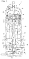
- FIG. 1 and FIG. 2 an embodiment of the present invention will be described using FIG. 1 and FIG. 2 .
- FIG. 1 shows a configuration diagram of a two-stage compression refrigeration system according to an embodiment of the present invention
- FIG. 2 shows a longitudinal section view of a two-stage compression that is used in the two-stage compression refrigeration system.
- a two-stage compression refrigeration system 1 configures a refrigerant circuit 10 with a closed cycle, by connecting, in order, a two-stage compressor 2, an oil separating device (oil separator) 3, a heat radiator (gas cooler) 4, a first expansion valve (decompression device) 5, a gas-liquid separating device (intermediate-pressure receiver) 6, a second expansion valve (decompression device) 7 and an evaporating device (evaporator) 8 through a refrigerant pipe 9.
- a refrigerant circuit 10 itself is well known.
- the above refrigerant circuit 10 communicates, between the oil separating device (oil separator) 3 and the two-stage compressor 2, with an oil return pipe 13 that returns the oil separated from a refrigerant gas by the oil separating device 3, to the two-stage compressor 2, and that includes an electromagnetic valve 11, which is opened at the time of operation, and a capillary tube 12 for flow rate regulation.
- the gas-liquid separating device (intermediate-pressure receiver) 6 communicates, between the gas-liquid separating device 6 and a closed housing 20 of the two-stage compressor 2, with a gas injection pipe 14 that injects an intermediate-pressure refrigerant gas separated within the gas-liquid separating device 6, into the closed housing 20 of the two-stage compressor 2.
- the gas-liquid separating device 6 configures an economizer cycle that separates, into gas and liquid, the refrigerant decompressed to an intermediate pressure by the first expansion valve (decompression device) 5 and injects the separated intermediate-pressure refrigerant gas into the intermediate-pressure refrigerant gas compressed by the two-stage compressor 2, and acts as a gas-liquid separation type economizer.
- a low-stage compressor 21 is fixedly disposed at a lower portion in the closed housing 20
- a high-stage compressor 22 is fixedly disposed at an upper portion
- an electric motor 23 to drive both compressors 21, 22 is fixedly disposed at an intermediate portion between them.
- the electric motor 23 is constituted by a stator 24 that is fixedly provided in the closed housing 20 by shrinkage fitting, press fitting or the like, and a rotor 25 that is provided on the inner circumference portion through an air cap.
- the rotor 25 is integrally provided with a drive shaft 26 that has an eccentric crank portion 26A at a lower portion and has a crank pin portion 26B at an upper end portion.
- the low-stage compressor 21 provided at a site below the electric motor 23 is a rotary-type compressor, and includes a cylinder body 27 that is fixedly provided in the closed housing 20, an upper bearing 29 and a lower bearing 30 that are fixedly provided on the upper and lower surfaces of the cylinder body 27 and that demarcate a cylinder chamber 28, a rotor 31 that is fitted into the eccentric crank portion 26A of the drive shaft 26 and that rotates in the cylinder chamber 28, a non-illustrated vane and vane pressing spring that partition the cylinder chamber 28 into a suction side and a discharge side, a discharge chamber 32, and the like.
- the low-stage compressor 21 is configured to compress, to an intermediate pressure, a low-pressure refrigerant gas sucked from the refrigerant circuit 10 side through a suction pipe 9B communicating with a suction port 33, and to discharge the refrigerant gas into the closed housing 20 through a discharge chamber 32.
- a rotary-type compressor is well known.
- the high-stage compressor 22 provided at a site above the electric motor 23 is a scroll-type compressor, and includes a bearing frame 34 that is fixedly provided in the closed housing 20, a fixed scroll 35 that is fixedly provided on the bearing frame 34, a revolving scroll 36 that meshes with the fixed scroll 35, that is slidably supported by a thrust bearing portion of the bearing frame 34, that is linked, through a drive bush and the like, with the crank pin portion 26B of the drive shaft 26 supported by the bearing frame 34, and that is driven in an orbital revolution manner, an Oldham ring 37 that blocks the rotation of the revolving scroll 36, a discharge valve 39 that opens and closes a discharge port 38 provided on the fixed scroll 35, a discharge chamber 41 that is formed by a cover 40, a discharge duct 42 that communicates with the discharge chamber 41, and the like.
- the high-stage compressor 22 sucks the intermediate-pressure refrigerant gas compressed by the low-stage compressor 21 and discharged into the closed housing 20, compresses the refrigerant gas in two stages, discharges the resulting refrigerant gas into the discharge chamber 41 as a high-temperature and high-pressure compressed gas, and then discharges the refrigerant gas from the discharge chamber 41 through the discharge duct 42 to a discharge pipe 9A on the side of the refrigerant circuit 10 connected with the two-stage compressor 2.
- the scroll-type compressor itself which constitutes such a high-stage compressor 22, is well known.
- a displacement oil pump 43 configured between the low-stage compressor 21 and the lower bearing 30 is provided at a lower end portion of the above drive shaft 26, and a lubricating oil (oil) 44 filled into a bottom portion in the closed housing 20 is fed to sliding portions of the low-stage compressor 21 and high-stage compressor 22, through an oil feeding hole 45 provided in the drive shaft 26, allowing for the lubrication of the sliding sites.
- the oil lubricating the sliding sites of the low-stage compressor 21 and high-stage compressor 22 because of having compatibility with the refrigerant, is dissolved into the compressed refrigerant gas, and is discharged from the two-stage compressor 2 to the refrigerant circuit 10 side together with the refrigerant.
- the performance of heat exchangers such as the heat radiator 4 and the evaporating device 8 degrades. Therefore, it is necessary to reduce the oil rise from the compressor 2 and the volume of the oil circulation to the refrigerant circuit 10 side, as much as possible.
- the oil separating device 3 is provided on the discharge pipe 9A connected with the two-stage compressor 2.
- the oil contained in the refrigerant gas is separated, and the volume of the oil circulating in the refrigerant circuit 10 is reduced. Therewith, the separated oil is returned into the closed housing 20 of the two-stage compressor 2, through the oil return pipe 13.
- the oil separated by the oil separating device 3 has the same temperature as the high-temperature refrigerant gas discharged from the two-stage compressor 2, and therefore, depending on the position of the return of the oil from the oil separating device 3, there is a fear of heating the low-pressure refrigerant gas to be sucked in the low-stage compressor 21 through the refrigerant suction pipe 9B and the suction port 33, or a fear of obstructing the heat radiation of the high-stage compressor 22.
- the embodiment adopts a configuration in which an oil return connection duct 46 communicating with a space portion 20A between the electric motor 23 and the low-stage compressor 21 is provided so as to penetrate the closed housing 20, between the low-stage compressor 21 and high-stage compressor 22 in the closed housing 20, and the oil return pipe 13 from the oil separating device (oil separator) 3 communicates with the oil return connection duct 46.
- the position of the oil return connection duct 46 should be an opposite position that faces the connection position of the suction pipe 9B with the suction port 33 of the low-stage compressor 21.
- the embodiment adopts a configuration in which an injection connection duct 47 for connecting the gas injection pipe 14, which injects the intermediate-pressure refrigerant gas from the gas-liquid separating device 6 into the closed housing 20 of the two-stage compressor 2, is provided so as to penetrate the space portion 20A in the closed housing 20, at an opposite position that faces the oil return connection duct 46, and communicates with the gas injection pipe 14.
- the gas injection pipe 14 also is between the low-stage compressor 21 and high-stage compressor 22 in the closed housing 20, and communicates with the space portion 20A between the electric motor 23 and the low-stage compressor 21.
- the embodiment exerts the following function effects.
- the low-pressure refrigerant gas sucked in the low-stage compressor (rotary-type compressor) 21 through the suction pipe 9B and the suction port 33 is compressed to an intermediate pressure, and is discharged into the closed housing 20 through the discharge chamber 32.
- the intermediate-pressure refrigerant gas is further sucked in the high-stage compressor (scroll-type compressor) 22, and is compressed in two stages, to become the high-temperature and high-pressure refrigerant gas, which is discharged into the discharge chamber 41.
- the high-temperature and high-pressure refrigerant gas discharged to the discharge chamber 41 is discharged to the discharge pipe 9A on the refrigerant circuit 10 side through the discharge duct 42, and is fed into the oil separating device (oil separator) 3 on the downstream side.
- the oil separating device 3 the oil contained in the refrigerant gas is separated, for example, by cyclone separation, and the refrigerant gas after the oil separation is fed to the heat radiator.(gas cooler) 4.
- the separated oil is returned into the closed housing 20 of the two-stage compressor 2 through the oil return pipe 13, while being regulated to a constant flow rate by the capillary tube 12. Thereby, a predetermined volume of circulation oil is constantly secured in the closed housing 20.
- the refrigerant fed to the heat radiator 4 is cooled by the heat exchange with the outside air or the like. Thereafter, the refrigerant passes through the first expansion valve (decompression device) 5, and in the process, is decompressed and cooled to the intermediate pressure.
- the refrigerant partially liquefies to become a gas-liquid two-phase state, and is introduced into the gas-liquid separating device (intermediate-pressure receiver) 6.
- the gas-liquid separating device 6 In the gas-liquid separating device 6, the refrigerant is separated into gas and liquid, and the separated gas refrigerant having the intermediate pressure is injected into the closed housing 20 having the intermediate pressure of the two-stage compressor 2, through the gas injection pipe 14.
- the liquid refrigerant is further decompressed and cooled in the second expansion valve (decompression device) 7 to become a gas-liquid two-phase refrigerant having a low pressure, and is fed to the evaporating device (evaporator) 8.
- the refrigerant fed to the evaporating device 8 is evaporated by the heat exchange with a cooling-target medium such as air, and a low-pressure refrigerant gas that is the evaporating gas is sucked again in the low-stage compressor 21 of the two-stage compressor 2 from the evaporating device 8 through the suction pipe 9B. Thereafter, the same operation is repeated.
- the cooling-target medium such as air cooled by the evaporation of the refrigerant in the evaporating device 8 is transferred to a cooling-target space or the like, and is used for air-conditioning or cooling the cooling-target space.
- the oil separated by the oil separating device 3 and returned into the closed housing 20 of the two-stage compressor 2 through the oil return pipe 13 has a high temperature, and depending on the return position, interferes with the heat radiation of the high-stage compressor 22 having a high temperature by the compression operation, or heats the low-pressure refrigerant gas to be sucked in the low-stage compressor 21, resulting in a fear of the degradation of the suction efficiency and the degradation of the performance of the compressor.
- the oil return pipe 13, between the low-stage compressor 21 and the high-stage compressor 22 communicates with the space portion 20A between the low-stage compressor 21 and the electric motor 23, and the oil separated by the oil separating device 3 is returned into the space portion 20A. Therefore, it is possible to solve the problem that the oil heats the high-stage compressor 22 and interferes with the heat radiation of the high-stage compressor 22.
- the intermediate-pressure refrigerant gas separated by the gas-liquid separating device 6 is injected into the above space portion 20A between the low-stage compressor 21 and the electric motor 23, through the gas injection pipe 14. Accordingly, even when the high-temperature oil is returned from the oil return pipe 13, the oil can be cooled by the intermediate-pressure refrigerant gas with a low temperature that is injected into the same space portion 20A. Therefore, the low-pressure refrigerant gas to be sucked in the low-stage compressor 21 is not heated by the return oil from the oil separating device 3, and it is possible to suppress the degradation of the performance of the compressor due to the degradation of the suction efficiency.
- the oil return pipe 13 and the gas injection pipe 14 individually communicate with the closed housing 20, between the low-stage compressor 21 and high-stage compressor 22 of the two-stage compressor 2. Therefore, though the intermediate-pressure refrigerant gas compressed by the low-stage compressor 21 is not cooled by an intermediate cooler and the oil from the oil separating device 3 is not cooled by the oil cooler, it is possible to avoid the heating of the refrigerant gas to be sucked in the low-stage compressor 21 within the two-stage compressor 2 and the interference with the heat radiation of the high-stage compressor 22, allowing for the prevention of the degradation of the performance. Further, it is possible to eliminate cost rise factors such as the increase in constituent devices and the complication of the configuration, and to achieve the simplification of the system configuration and the reduction in cost.
- the intermediate-pressure refrigerant gas to be injected into the closed housing 20 through the gas injection pipe 14, independently from the return oil from the oil separating device 3, can be injected into the closed housing 20, at a position distant from the high-stage compressor 22. Therefore, it is possible to reduce the volume of the oil contained in the refrigerant gas to be sucked in the high-stage compressor 22, to reduce the oil rise and thus the oil circulation volume, and to surely secure a required volume of lubricating oil in the two-stage compressor 2. Therewith, it is possible to suppress the degradation of the system efficiency due to the increase in oil circulation volume.
- both of the oil return pipe 13 and the gas injection pipe 14 communicate with the space portion 20A between the lower portion of the electric motor 23 and the low-stage compressor 21, the oil return pipe 13 and the gas injection pipe 14 can communicate with the closed housing 20, at a position sufficiently distant from the high-stage compressor 22. Therefore, it is possible to prevent the heating of the high-stage compressor 22 by the high-temperature return oil, to secure the heat radiation performance of the high-stage compressor 22, and to block the overheating. Further, it is possible to surely cool the high-temperature return oil by the low-temperature injection gas, and therefore, it is possible to effectively suppress the heating of the refrigerant gas to be sucked in the low-stage compressor 21, and to minimize the degradation of the suction efficiency and the degradation of the performance.
- the oil return pipe 13 communicates with the space portion 20A in the closed housing 20, at the opposite position that faces the connection position of the refrigerant suction pipe 9B with the low-stage compressor 21, and the gas injection pipe 14 communicates with the space portion 20A in the closed housing 20, at the opposite position that faces the oil return pipe 13. Therefore, the oil return pipe 13 is placed as far as possible from the refrigerant suction pipe position on the low-stage compressor 21, and thereby, it is possible to minimize the heating of the suction gas by the high-temperature return oil.
- the gas injection pipe 14 is placed as close as possible to the refrigerant suction pipe position on the low-stage compressor 21, and the suction port 33 and the periphery of the suction pipe 9A in the low-stage compressor 21 are covered with the low-temperature injection gas. Thereby, it is possible to effectively suppress the heating of the suction gas.
- the low-stage compressor 21 of the two-stage compressor 2 which is provided at the lower site in the closed housing 20, is a widely practiced and reliable rotary-type compressor configured to directly suck the low-pressure refrigerant gas through the suction pipe 9B and discharge the compressed refrigerant gas into the closed housing 20, and the high-stage compressor 22, which is provided at the upper site in the closed housing 20, is a widely practiced and reliable scroll-type compressor configured to suck and compress the intermediate-pressure refrigerant gas in the closed housing 20, discharge the high-pressure refrigerant gas to the discharge chamber 41, and directly discharge the high-pressure refrigerant gas out of the compressor. Therefore, it is possible to secure the reliability and performance of the two-stage compressor 2.
- the oil return pipe 13 and the gas injection pipe 14 are configured to directly communicate with the closed housing 20 of the two-stage compressor 2, and therefore, it is possible to suppress the heating of the suction gas, the overheating of the high-stage compressor 22, the oil rise and others in the two-stage compressor 2, while achieving the simplification of the configuration of the two-stage compression refrigeration system. As a result, it is possible to enhance the reliability and performance of the system, and to achieve a high efficiency and a high performance of the two-stage compression refrigeration system.
- the present invention is not limited to the invention in the above embodiment, and modifications can be appropriately made without departing from the scope.
- the above embodiment provides the gas-liquid separating device (intermediate-pressure receiver) 6 downstream of the first expansion valve (decompression device) 5 as an economizer, and configures the economizer cycle in which the intermediate-pressure refrigerant gas separated in the gas-liquid separating device 6 is injected into the refrigerant gas compressed in the two-stage compressor 2.
- it is allowed to adopt an internal heat exchanger type economizer cycle that is provided with an internal heat exchanger (supercooling heat exchanger) instead of the gas-liquid separating device 6.
- the internal heat exchanger type economizer cycle is configured to partially split the refrigerant from the heat radiator (gas cooler), to perform the heat exchange of the split refrigerant with the refrigerant flowing through the refrigerant circuit 10 side in the internal heat exchanger after the decompression by an expansion valve (decompression device), to supercool the refrigerant flowing through the refrigerant circuit 10 side, and to inject the evaporated intermediate-pressure split refrigerant gas into the refrigerant gas compressed in the two-stage compressor 2, through the gas injection pipe 14, and can obtain the same economizer effect as the economizer cycle using the gas-liquid separating device 6.
- the above embodiment adopts a configuration in which the oil return pipe 13 communicates with the space portion 20A in the closed housing 20 at the opposite position that faces the refrigerant suction pipe position on the low-stage compressor 21 and the gas injection pipe 14 communicates at the opposite position that faces the oil return pipe 13.
- the facing opposite positions do not always need to be opposite positions that face each other at 180 degrees, and only need to be positions that face each other in a certain range (for example, a range of plus or minus 45 degrees). That case is also included in the present invention.
Applications Claiming Priority (1)
| Application Number | Priority Date | Filing Date | Title |
|---|---|---|---|
| JP2015167987A JP6594707B2 (ja) | 2015-08-27 | 2015-08-27 | 2段圧縮冷凍システム |
Publications (2)
| Publication Number | Publication Date |
|---|---|
| EP3136020A1 true EP3136020A1 (fr) | 2017-03-01 |
| EP3136020B1 EP3136020B1 (fr) | 2019-04-17 |
Family
ID=57144718
Family Applications (1)
| Application Number | Title | Priority Date | Filing Date |
|---|---|---|---|
| EP16185537.4A Active EP3136020B1 (fr) | 2015-08-27 | 2016-08-24 | Système de réfrigération par compression à deux étages |
Country Status (2)
| Country | Link |
|---|---|
| EP (1) | EP3136020B1 (fr) |
| JP (1) | JP6594707B2 (fr) |
Cited By (14)
| Publication number | Priority date | Publication date | Assignee | Title |
|---|---|---|---|---|
| CN109404279A (zh) * | 2018-10-10 | 2019-03-01 | 合肥通用机械研究院有限公司 | 带有电机腔冷却的热泵压缩机及其系统 |
| EP3578817A1 (fr) * | 2018-06-06 | 2019-12-11 | FRAUNHOFER-GESELLSCHAFT zur Förderung der angewandten Forschung e.V. | Compresseur, pompe à chaleur ou installation de climatisation ou machine de réfrigération et procédé de compression |
| EP3604813A1 (fr) * | 2018-08-01 | 2020-02-05 | Fu Sheng Industrial Co., Ltd. | Compresseur à deux étages |
| CN111108333A (zh) * | 2017-09-28 | 2020-05-05 | 三菱电机株式会社 | 油分离器以及具备油分离器的空调机 |
| CN111963437A (zh) * | 2019-07-31 | 2020-11-20 | 宁波鲍斯能源装备股份有限公司 | 一种一体式螺杆涡旋双级压缩机 |
| CN112771323A (zh) * | 2018-09-28 | 2021-05-07 | 大金工业株式会社 | 多级压缩系统 |
| CN112815584A (zh) * | 2021-02-24 | 2021-05-18 | 孟雷 | 一种低充注量的满液供液系统及其回油方法 |
| CN113669936A (zh) * | 2021-07-06 | 2021-11-19 | 北京国家速滑馆经营有限责任公司 | 一种用于二氧化碳跨临界制冷系统的回油系统 |
| CN113883600A (zh) * | 2021-11-01 | 2022-01-04 | 罗长安 | 一种空调双压缩机制冷系统及空调 |
| US11415342B2 (en) | 2018-09-28 | 2022-08-16 | Daikin Industries, Ltd. | Multistage compression system |
| US11428225B2 (en) | 2018-09-28 | 2022-08-30 | Daikin Industries, Ltd. | Multistage compression system |
| US11428226B2 (en) | 2018-09-28 | 2022-08-30 | Daikin Industries, Ltd. | Multistage compression system |
| US11754321B2 (en) * | 2018-03-27 | 2023-09-12 | Bitzer Kuehlmaschinenbau Gmbh | Refrigeration system |
| EP4198416A4 (fr) * | 2020-09-29 | 2024-01-10 | Mitsubishi Heavy Ind Thermal Systems Ltd | Machine frigorifique |
Families Citing this family (3)
| Publication number | Priority date | Publication date | Assignee | Title |
|---|---|---|---|---|
| JP6702400B1 (ja) * | 2018-12-13 | 2020-06-03 | ダイキン工業株式会社 | 多段圧縮システム |
| JP2022181836A (ja) | 2021-05-27 | 2022-12-08 | 三菱重工サーマルシステムズ株式会社 | 多段圧縮冷凍装置 |
| JP2022181837A (ja) | 2021-05-27 | 2022-12-08 | 三菱重工サーマルシステムズ株式会社 | 多段圧縮冷凍装置 |
Citations (6)
| Publication number | Priority date | Publication date | Assignee | Title |
|---|---|---|---|---|
| US20100143172A1 (en) * | 2006-12-28 | 2010-06-10 | Mitsubishi Heavy Industries, Ltd. | Multistage Compressor |
| EP2236828A1 (fr) * | 2008-01-29 | 2010-10-06 | Mitsubishi Heavy Industries, Ltd. | Compresseur à spirale |
| JP2011007351A (ja) | 2009-06-23 | 2011-01-13 | Sanyo Electric Co Ltd | 冷凍装置 |
| JP2011232000A (ja) | 2010-04-28 | 2011-11-17 | Mitsubishi Heavy Ind Ltd | Co2冷媒を用いたヒートポンプ給湯装置 |
| WO2013073063A1 (fr) * | 2011-11-18 | 2013-05-23 | 三洋電機株式会社 | Appareil de réfrigération |
| WO2015077275A1 (fr) * | 2013-11-25 | 2015-05-28 | The Coca-Cola Company | Compresseur ayant un séparateur d'huile |
Family Cites Families (3)
| Publication number | Priority date | Publication date | Assignee | Title |
|---|---|---|---|---|
| JP3903409B2 (ja) * | 2000-03-29 | 2007-04-11 | 三菱電機株式会社 | 二段圧縮冷凍機 |
| JP4949817B2 (ja) * | 2006-12-08 | 2012-06-13 | 三菱重工業株式会社 | 多段圧縮機およびそれを用いた冷凍サイクル |
| JP5430598B2 (ja) * | 2011-03-28 | 2014-03-05 | 三菱電機株式会社 | 冷凍サイクル装置 |
-
2015
- 2015-08-27 JP JP2015167987A patent/JP6594707B2/ja active Active
-
2016
- 2016-08-24 EP EP16185537.4A patent/EP3136020B1/fr active Active
Patent Citations (8)
| Publication number | Priority date | Publication date | Assignee | Title |
|---|---|---|---|---|
| US20100143172A1 (en) * | 2006-12-28 | 2010-06-10 | Mitsubishi Heavy Industries, Ltd. | Multistage Compressor |
| EP2236828A1 (fr) * | 2008-01-29 | 2010-10-06 | Mitsubishi Heavy Industries, Ltd. | Compresseur à spirale |
| JP2011007351A (ja) | 2009-06-23 | 2011-01-13 | Sanyo Electric Co Ltd | 冷凍装置 |
| JP5586880B2 (ja) | 2009-06-23 | 2014-09-10 | 三洋電機株式会社 | 冷凍装置 |
| JP2011232000A (ja) | 2010-04-28 | 2011-11-17 | Mitsubishi Heavy Ind Ltd | Co2冷媒を用いたヒートポンプ給湯装置 |
| JP5705455B2 (ja) | 2010-04-28 | 2015-04-22 | 三菱重工業株式会社 | Co2冷媒を用いたヒートポンプ給湯装置 |
| WO2013073063A1 (fr) * | 2011-11-18 | 2013-05-23 | 三洋電機株式会社 | Appareil de réfrigération |
| WO2015077275A1 (fr) * | 2013-11-25 | 2015-05-28 | The Coca-Cola Company | Compresseur ayant un séparateur d'huile |
Cited By (22)
| Publication number | Priority date | Publication date | Assignee | Title |
|---|---|---|---|---|
| CN111108333A (zh) * | 2017-09-28 | 2020-05-05 | 三菱电机株式会社 | 油分离器以及具备油分离器的空调机 |
| CN111108333B (zh) * | 2017-09-28 | 2021-11-30 | 三菱电机株式会社 | 油分离器以及具备油分离器的空调机 |
| US11754321B2 (en) * | 2018-03-27 | 2023-09-12 | Bitzer Kuehlmaschinenbau Gmbh | Refrigeration system |
| EP3578817A1 (fr) * | 2018-06-06 | 2019-12-11 | FRAUNHOFER-GESELLSCHAFT zur Förderung der angewandten Forschung e.V. | Compresseur, pompe à chaleur ou installation de climatisation ou machine de réfrigération et procédé de compression |
| US10948220B2 (en) | 2018-08-01 | 2021-03-16 | Fu Sheng Industrial Co., Ltd. | Two-stage compressor |
| CN110792596A (zh) * | 2018-08-01 | 2020-02-14 | 复盛股份有限公司 | 双级压缩机 |
| CN110792596B (zh) * | 2018-08-01 | 2021-08-27 | 复盛股份有限公司 | 双级压缩机 |
| EP3604813A1 (fr) * | 2018-08-01 | 2020-02-05 | Fu Sheng Industrial Co., Ltd. | Compresseur à deux étages |
| US11415342B2 (en) | 2018-09-28 | 2022-08-16 | Daikin Industries, Ltd. | Multistage compression system |
| CN112771323A (zh) * | 2018-09-28 | 2021-05-07 | 大金工业株式会社 | 多级压缩系统 |
| US11428226B2 (en) | 2018-09-28 | 2022-08-30 | Daikin Industries, Ltd. | Multistage compression system |
| EP3859233A4 (fr) * | 2018-09-28 | 2021-11-24 | Daikin Industries, Ltd. | Système de compression à étages multiples |
| US11428225B2 (en) | 2018-09-28 | 2022-08-30 | Daikin Industries, Ltd. | Multistage compression system |
| CN109404279A (zh) * | 2018-10-10 | 2019-03-01 | 合肥通用机械研究院有限公司 | 带有电机腔冷却的热泵压缩机及其系统 |
| CN111963437A (zh) * | 2019-07-31 | 2020-11-20 | 宁波鲍斯能源装备股份有限公司 | 一种一体式螺杆涡旋双级压缩机 |
| CN111963437B (zh) * | 2019-07-31 | 2022-11-04 | 宁波鲍斯能源装备股份有限公司 | 一种一体式螺杆涡旋双级压缩机 |
| EP4198416A4 (fr) * | 2020-09-29 | 2024-01-10 | Mitsubishi Heavy Ind Thermal Systems Ltd | Machine frigorifique |
| CN112815584B (zh) * | 2021-02-24 | 2023-05-23 | 孟雷 | 一种低充注量的满液供液系统及其回油方法 |
| CN112815584A (zh) * | 2021-02-24 | 2021-05-18 | 孟雷 | 一种低充注量的满液供液系统及其回油方法 |
| CN113669936A (zh) * | 2021-07-06 | 2021-11-19 | 北京国家速滑馆经营有限责任公司 | 一种用于二氧化碳跨临界制冷系统的回油系统 |
| CN113883600A (zh) * | 2021-11-01 | 2022-01-04 | 罗长安 | 一种空调双压缩机制冷系统及空调 |
| CN113883600B (zh) * | 2021-11-01 | 2023-02-10 | 湖北璞瑞斯节能技术服务有限公司 | 一种空调双压缩机制冷系统及空调 |
Also Published As
| Publication number | Publication date |
|---|---|
| EP3136020B1 (fr) | 2019-04-17 |
| JP6594707B2 (ja) | 2019-10-23 |
| JP2017044420A (ja) | 2017-03-02 |
Similar Documents
| Publication | Publication Date | Title |
|---|---|---|
| EP3136020B1 (fr) | Système de réfrigération par compression à deux étages | |
| EP2055956B1 (fr) | Compresseur à plusieurs étages | |
| US7563080B2 (en) | Rotary compressor | |
| US7722346B2 (en) | Oil supply method of two-stage screw compressor, two-stage screw compressor applying the method, and method of operating refrigerating machine having the compressor | |
| US10378539B2 (en) | System including high-side and low-side compressors | |
| EP1953388B1 (fr) | Compresseur à plusieurs étages | |
| JP4814167B2 (ja) | 多段圧縮機 | |
| US8419395B2 (en) | Compressor and refrigeration apparatus | |
| EP3382205B1 (fr) | Compresseur | |
| EP2551526B1 (fr) | Compresseur rotatif à deux étages | |
| CN108138771B (zh) | 压缩机轴承壳体排放装置 | |
| CN112752934B (zh) | 多级压缩系统 | |
| EP3575605B1 (fr) | Compresseur hermétique | |
| US8245528B2 (en) | Fluid machine | |
| JP6160502B2 (ja) | 冷凍サイクル装置 | |
| CN213066668U (zh) | 供热、通风、空气调节和制冷系统及用于该系统的压缩机 | |
| CN111868384B (zh) | 多级压缩机 | |
| JP2017053279A (ja) | スクロール圧縮機 |
Legal Events
| Date | Code | Title | Description |
|---|---|---|---|
| PUAI | Public reference made under article 153(3) epc to a published international application that has entered the european phase |
Free format text: ORIGINAL CODE: 0009012 |
|
| STAA | Information on the status of an ep patent application or granted ep patent |
Free format text: STATUS: THE APPLICATION HAS BEEN PUBLISHED |
|
| AK | Designated contracting states |
Kind code of ref document: A1 Designated state(s): AL AT BE BG CH CY CZ DE DK EE ES FI FR GB GR HR HU IE IS IT LI LT LU LV MC MK MT NL NO PL PT RO RS SE SI SK SM TR |
|
| AX | Request for extension of the european patent |
Extension state: BA ME |
|
| STAA | Information on the status of an ep patent application or granted ep patent |
Free format text: STATUS: REQUEST FOR EXAMINATION WAS MADE |
|
| 17P | Request for examination filed |
Effective date: 20170831 |
|
| RBV | Designated contracting states (corrected) |
Designated state(s): AL AT BE BG CH CY CZ DE DK EE ES FI FR GB GR HR HU IE IS IT LI LT LU LV MC MK MT NL NO PL PT RO RS SE SI SK SM TR |
|
| RAP1 | Party data changed (applicant data changed or rights of an application transferred) |
Owner name: MITSUBISHI HEAVY INDUSTRIES THERMAL SYSTEMS, LTD. |
|
| STAA | Information on the status of an ep patent application or granted ep patent |
Free format text: STATUS: EXAMINATION IS IN PROGRESS |
|
| 17Q | First examination report despatched |
Effective date: 20180209 |
|
| GRAP | Despatch of communication of intention to grant a patent |
Free format text: ORIGINAL CODE: EPIDOSNIGR1 |
|
| STAA | Information on the status of an ep patent application or granted ep patent |
Free format text: STATUS: GRANT OF PATENT IS INTENDED |
|
| RIC1 | Information provided on ipc code assigned before grant |
Ipc: F25B 1/10 20060101AFI20181112BHEP Ipc: F04B 27/00 20060101ALN20181112BHEP Ipc: F25B 31/02 20060101ALI20181112BHEP Ipc: F25B 31/00 20060101ALN20181112BHEP |
|
| INTG | Intention to grant announced |
Effective date: 20181128 |
|
| RIC1 | Information provided on ipc code assigned before grant |
Ipc: F25B 1/10 20060101AFI20181119BHEP Ipc: F25B 31/00 20060101ALN20181119BHEP Ipc: F04B 27/00 20060101ALN20181119BHEP Ipc: F25B 31/02 20060101ALI20181119BHEP |
|
| GRAS | Grant fee paid |
Free format text: ORIGINAL CODE: EPIDOSNIGR3 |
|
| GRAA | (expected) grant |
Free format text: ORIGINAL CODE: 0009210 |
|
| STAA | Information on the status of an ep patent application or granted ep patent |
Free format text: STATUS: THE PATENT HAS BEEN GRANTED |
|
| AK | Designated contracting states |
Kind code of ref document: B1 Designated state(s): AL AT BE BG CH CY CZ DE DK EE ES FI FR GB GR HR HU IE IS IT LI LT LU LV MC MK MT NL NO PL PT RO RS SE SI SK SM TR |
|
| REG | Reference to a national code |
Ref country code: GB Ref legal event code: FG4D |
|
| REG | Reference to a national code |
Ref country code: CH Ref legal event code: EP |
|
| REG | Reference to a national code |
Ref country code: DE Ref legal event code: R096 Ref document number: 602016012474 Country of ref document: DE |
|
| REG | Reference to a national code |
Ref country code: AT Ref legal event code: REF Ref document number: 1121981 Country of ref document: AT Kind code of ref document: T Effective date: 20190515 Ref country code: IE Ref legal event code: FG4D |
|
| REG | Reference to a national code |
Ref country code: NL Ref legal event code: MP Effective date: 20190417 |
|
| REG | Reference to a national code |
Ref country code: LT Ref legal event code: MG4D |
|
| PG25 | Lapsed in a contracting state [announced via postgrant information from national office to epo] |
Ref country code: NL Free format text: LAPSE BECAUSE OF FAILURE TO SUBMIT A TRANSLATION OF THE DESCRIPTION OR TO PAY THE FEE WITHIN THE PRESCRIBED TIME-LIMIT Effective date: 20190417 |
|
| PG25 | Lapsed in a contracting state [announced via postgrant information from national office to epo] |
Ref country code: LT Free format text: LAPSE BECAUSE OF FAILURE TO SUBMIT A TRANSLATION OF THE DESCRIPTION OR TO PAY THE FEE WITHIN THE PRESCRIBED TIME-LIMIT Effective date: 20190417 Ref country code: HR Free format text: LAPSE BECAUSE OF FAILURE TO SUBMIT A TRANSLATION OF THE DESCRIPTION OR TO PAY THE FEE WITHIN THE PRESCRIBED TIME-LIMIT Effective date: 20190417 Ref country code: SE Free format text: LAPSE BECAUSE OF FAILURE TO SUBMIT A TRANSLATION OF THE DESCRIPTION OR TO PAY THE FEE WITHIN THE PRESCRIBED TIME-LIMIT Effective date: 20190417 Ref country code: FI Free format text: LAPSE BECAUSE OF FAILURE TO SUBMIT A TRANSLATION OF THE DESCRIPTION OR TO PAY THE FEE WITHIN THE PRESCRIBED TIME-LIMIT Effective date: 20190417 Ref country code: NO Free format text: LAPSE BECAUSE OF FAILURE TO SUBMIT A TRANSLATION OF THE DESCRIPTION OR TO PAY THE FEE WITHIN THE PRESCRIBED TIME-LIMIT Effective date: 20190717 Ref country code: PT Free format text: LAPSE BECAUSE OF FAILURE TO SUBMIT A TRANSLATION OF THE DESCRIPTION OR TO PAY THE FEE WITHIN THE PRESCRIBED TIME-LIMIT Effective date: 20190817 Ref country code: AL Free format text: LAPSE BECAUSE OF FAILURE TO SUBMIT A TRANSLATION OF THE DESCRIPTION OR TO PAY THE FEE WITHIN THE PRESCRIBED TIME-LIMIT Effective date: 20190417 Ref country code: ES Free format text: LAPSE BECAUSE OF FAILURE TO SUBMIT A TRANSLATION OF THE DESCRIPTION OR TO PAY THE FEE WITHIN THE PRESCRIBED TIME-LIMIT Effective date: 20190417 |
|
| PG25 | Lapsed in a contracting state [announced via postgrant information from national office to epo] |
Ref country code: BG Free format text: LAPSE BECAUSE OF FAILURE TO SUBMIT A TRANSLATION OF THE DESCRIPTION OR TO PAY THE FEE WITHIN THE PRESCRIBED TIME-LIMIT Effective date: 20190717 Ref country code: LV Free format text: LAPSE BECAUSE OF FAILURE TO SUBMIT A TRANSLATION OF THE DESCRIPTION OR TO PAY THE FEE WITHIN THE PRESCRIBED TIME-LIMIT Effective date: 20190417 Ref country code: RS Free format text: LAPSE BECAUSE OF FAILURE TO SUBMIT A TRANSLATION OF THE DESCRIPTION OR TO PAY THE FEE WITHIN THE PRESCRIBED TIME-LIMIT Effective date: 20190417 Ref country code: GR Free format text: LAPSE BECAUSE OF FAILURE TO SUBMIT A TRANSLATION OF THE DESCRIPTION OR TO PAY THE FEE WITHIN THE PRESCRIBED TIME-LIMIT Effective date: 20190718 Ref country code: PL Free format text: LAPSE BECAUSE OF FAILURE TO SUBMIT A TRANSLATION OF THE DESCRIPTION OR TO PAY THE FEE WITHIN THE PRESCRIBED TIME-LIMIT Effective date: 20190417 |
|
| REG | Reference to a national code |
Ref country code: AT Ref legal event code: MK05 Ref document number: 1121981 Country of ref document: AT Kind code of ref document: T Effective date: 20190417 |
|
| PG25 | Lapsed in a contracting state [announced via postgrant information from national office to epo] |
Ref country code: IS Free format text: LAPSE BECAUSE OF FAILURE TO SUBMIT A TRANSLATION OF THE DESCRIPTION OR TO PAY THE FEE WITHIN THE PRESCRIBED TIME-LIMIT Effective date: 20190817 |
|
| REG | Reference to a national code |
Ref country code: DE Ref legal event code: R097 Ref document number: 602016012474 Country of ref document: DE |
|
| PG25 | Lapsed in a contracting state [announced via postgrant information from national office to epo] |
Ref country code: EE Free format text: LAPSE BECAUSE OF FAILURE TO SUBMIT A TRANSLATION OF THE DESCRIPTION OR TO PAY THE FEE WITHIN THE PRESCRIBED TIME-LIMIT Effective date: 20190417 Ref country code: RO Free format text: LAPSE BECAUSE OF FAILURE TO SUBMIT A TRANSLATION OF THE DESCRIPTION OR TO PAY THE FEE WITHIN THE PRESCRIBED TIME-LIMIT Effective date: 20190417 Ref country code: SK Free format text: LAPSE BECAUSE OF FAILURE TO SUBMIT A TRANSLATION OF THE DESCRIPTION OR TO PAY THE FEE WITHIN THE PRESCRIBED TIME-LIMIT Effective date: 20190417 Ref country code: AT Free format text: LAPSE BECAUSE OF FAILURE TO SUBMIT A TRANSLATION OF THE DESCRIPTION OR TO PAY THE FEE WITHIN THE PRESCRIBED TIME-LIMIT Effective date: 20190417 Ref country code: DK Free format text: LAPSE BECAUSE OF FAILURE TO SUBMIT A TRANSLATION OF THE DESCRIPTION OR TO PAY THE FEE WITHIN THE PRESCRIBED TIME-LIMIT Effective date: 20190417 Ref country code: CZ Free format text: LAPSE BECAUSE OF FAILURE TO SUBMIT A TRANSLATION OF THE DESCRIPTION OR TO PAY THE FEE WITHIN THE PRESCRIBED TIME-LIMIT Effective date: 20190417 |
|
| PLBE | No opposition filed within time limit |
Free format text: ORIGINAL CODE: 0009261 |
|
| STAA | Information on the status of an ep patent application or granted ep patent |
Free format text: STATUS: NO OPPOSITION FILED WITHIN TIME LIMIT |
|
| PG25 | Lapsed in a contracting state [announced via postgrant information from national office to epo] |
Ref country code: SM Free format text: LAPSE BECAUSE OF FAILURE TO SUBMIT A TRANSLATION OF THE DESCRIPTION OR TO PAY THE FEE WITHIN THE PRESCRIBED TIME-LIMIT Effective date: 20190417 Ref country code: IT Free format text: LAPSE BECAUSE OF FAILURE TO SUBMIT A TRANSLATION OF THE DESCRIPTION OR TO PAY THE FEE WITHIN THE PRESCRIBED TIME-LIMIT Effective date: 20190417 |
|
| 26N | No opposition filed |
Effective date: 20200120 |
|
| PG25 | Lapsed in a contracting state [announced via postgrant information from national office to epo] |
Ref country code: TR Free format text: LAPSE BECAUSE OF FAILURE TO SUBMIT A TRANSLATION OF THE DESCRIPTION OR TO PAY THE FEE WITHIN THE PRESCRIBED TIME-LIMIT Effective date: 20190417 |
|
| PG25 | Lapsed in a contracting state [announced via postgrant information from national office to epo] |
Ref country code: CH Free format text: LAPSE BECAUSE OF NON-PAYMENT OF DUE FEES Effective date: 20190831 Ref country code: LU Free format text: LAPSE BECAUSE OF NON-PAYMENT OF DUE FEES Effective date: 20190824 Ref country code: SI Free format text: LAPSE BECAUSE OF FAILURE TO SUBMIT A TRANSLATION OF THE DESCRIPTION OR TO PAY THE FEE WITHIN THE PRESCRIBED TIME-LIMIT Effective date: 20190417 Ref country code: MC Free format text: LAPSE BECAUSE OF FAILURE TO SUBMIT A TRANSLATION OF THE DESCRIPTION OR TO PAY THE FEE WITHIN THE PRESCRIBED TIME-LIMIT Effective date: 20190417 Ref country code: LI Free format text: LAPSE BECAUSE OF NON-PAYMENT OF DUE FEES Effective date: 20190831 |
|
| REG | Reference to a national code |
Ref country code: BE Ref legal event code: MM Effective date: 20190831 |
|
| PG25 | Lapsed in a contracting state [announced via postgrant information from national office to epo] |
Ref country code: IE Free format text: LAPSE BECAUSE OF NON-PAYMENT OF DUE FEES Effective date: 20190824 |
|
| PG25 | Lapsed in a contracting state [announced via postgrant information from national office to epo] |
Ref country code: BE Free format text: LAPSE BECAUSE OF NON-PAYMENT OF DUE FEES Effective date: 20190831 |
|
| PG25 | Lapsed in a contracting state [announced via postgrant information from national office to epo] |
Ref country code: CY Free format text: LAPSE BECAUSE OF FAILURE TO SUBMIT A TRANSLATION OF THE DESCRIPTION OR TO PAY THE FEE WITHIN THE PRESCRIBED TIME-LIMIT Effective date: 20190417 |
|
| PG25 | Lapsed in a contracting state [announced via postgrant information from national office to epo] |
Ref country code: MT Free format text: LAPSE BECAUSE OF FAILURE TO SUBMIT A TRANSLATION OF THE DESCRIPTION OR TO PAY THE FEE WITHIN THE PRESCRIBED TIME-LIMIT Effective date: 20190417 Ref country code: HU Free format text: LAPSE BECAUSE OF FAILURE TO SUBMIT A TRANSLATION OF THE DESCRIPTION OR TO PAY THE FEE WITHIN THE PRESCRIBED TIME-LIMIT; INVALID AB INITIO Effective date: 20160824 |
|
| PG25 | Lapsed in a contracting state [announced via postgrant information from national office to epo] |
Ref country code: MK Free format text: LAPSE BECAUSE OF FAILURE TO SUBMIT A TRANSLATION OF THE DESCRIPTION OR TO PAY THE FEE WITHIN THE PRESCRIBED TIME-LIMIT Effective date: 20190417 |
|
| REG | Reference to a national code |
Ref country code: DE Ref legal event code: R082 Ref document number: 602016012474 Country of ref document: DE Representative=s name: CBDL PATENTANWAELTE GBR, DE |
|
| PGFP | Annual fee paid to national office [announced via postgrant information from national office to epo] |
Ref country code: GB Payment date: 20230706 Year of fee payment: 8 |
|
| PGFP | Annual fee paid to national office [announced via postgrant information from national office to epo] |
Ref country code: FR Payment date: 20230703 Year of fee payment: 8 Ref country code: DE Payment date: 20230627 Year of fee payment: 8 |