EP3135872A1 - Montageverfahren eines elektromagnetischen ventilstellglieds und eines kühlölkreislaufs - Google Patents
Montageverfahren eines elektromagnetischen ventilstellglieds und eines kühlölkreislaufs Download PDFInfo
- Publication number
- EP3135872A1 EP3135872A1 EP16177913.7A EP16177913A EP3135872A1 EP 3135872 A1 EP3135872 A1 EP 3135872A1 EP 16177913 A EP16177913 A EP 16177913A EP 3135872 A1 EP3135872 A1 EP 3135872A1
- Authority
- EP
- European Patent Office
- Prior art keywords
- tray
- valve
- cylinder head
- carcass
- low
- Prior art date
- Legal status (The legal status is an assumption and is not a legal conclusion. Google has not performed a legal analysis and makes no representation as to the accuracy of the status listed.)
- Withdrawn
Links
Images


Classifications
-
- F—MECHANICAL ENGINEERING; LIGHTING; HEATING; WEAPONS; BLASTING
- F01—MACHINES OR ENGINES IN GENERAL; ENGINE PLANTS IN GENERAL; STEAM ENGINES
- F01L—CYCLICALLY OPERATING VALVES FOR MACHINES OR ENGINES
- F01L9/00—Valve-gear or valve arrangements actuated non-mechanically
- F01L9/20—Valve-gear or valve arrangements actuated non-mechanically by electric means
- F01L9/21—Valve-gear or valve arrangements actuated non-mechanically by electric means actuated by solenoids
- F01L2009/2157—Actuator cooling means
Definitions
- the invention relates to the field of automobiles, and more specifically to internal combustion engines of motor vehicles.
- An internal combustion engine conventionally comprises a cylinder block provided with at least one cylinder comprising a jacket in which a piston, of shape complementary to the jacket, is movable in a translation movement, along an edge of the jacket. .
- the piston oscillates in the cylinder between an extreme position called top dead center (TDC) and an extreme position called bottom dead center (PMB).
- TDC top dead center
- PMB bottom dead center
- a cylinder head, integral with the cylinder, forms, with the jacket and the piston, a combustion chamber.
- the chamber is fed, during each cycle (four-stroke cycle defined by two complete oscillations of the piston or two-stroke cycle defined by a complete oscillation of the piston), by a mixture comprising air and fuel (air / fuel mixture). fuel).
- Each cycle comprises in particular an "injection” phase of the air / fuel mixture, into the combustion chamber, through an intake manifold, upstream of an "exhaust” phase of the combustion chamber, through a manifold exhaust, gases resulting from combustion of the air / fuel mixture.
- the cylinder head comprises an intake valve adapted to seal the intake manifold and an exhaust valve adapted to seal the exhaust manifold.
- the document DE 100 09 299 discloses an internal combustion engine comprising a cylinder head provided with electromagnetic actuators adapted to control an opening or closing of the valves.
- the electromagnetic actuators are arranged in a closed container with a lid.
- the electromagnetic actuator comprises a frame integral with the yoke, defining a magnetic circuit and including a movable element integral with the valve.
- the cylinder head cover includes fins for air cooling the electromagnetic actuators.
- Such a cylinder head effectively controls the opening or closing of the valves.
- the air cooling of the electromagnetic actuators is not able to sufficiently cool the actuators can perform up to 3000 movements per minute.
- such an arrangement of the elements does not allow optimum compactness of the engine.
- a first objective is to propose a cylinder head comprising a hydraulically cooled electromagnetic actuator.
- a second objective is to propose a method of assembling the cylinder head.
- a third objective is to propose an internal combustion engine comprising such a cylinder head.
- the cylinder head capable of increasing the compactness of the internal combustion engine, optimizes the cooling of the electromagnetic actuator.
- an internal combustion engine comprising a lubrication circuit, characterized in that it comprises a yoke of the invention whose hydraulic circuit is connected to the lubrication circuit of the internal combustion engine.
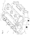
- FIG. 1 On the figure 1 is represented a vehicle 1 automobile comprising an internal combustion engine 2 .
- the engine 2 comprises a cylinder block 3 surmounted by a yoke 4 provided with a low part 5 adapted to close the cylinder block 3 in a sealed manner.
- the yoke 4 is substantially symmetrical along a plane P defining two identical rows 6 .
- Each row 6 of the yoke 4 can be subdivided into three substantially identical portions 7 .
- the lower part of the cylinder head 4 comprises four holes 8 for fastening.
- Each portion 7 comprises two through-holes 9 communicating with a tubing 10.
- the tubings 10 each comprise two housings 11 substantially centered with the holes 9 of passage.
- Each portion 7 of the yoke 4 comprises two valves 12 each provided with a tail 13 of complementary shape to the shape of the hole 9 of passage, movable in a translational movement in the hole 9 passage.
- the valve 12 comprises a conical tip 14, a screw thread 15.
- the valve 12 comprises a head 16 capable of being housed in the housing 11 and seal tubes 10.
- Each row 6 of the yoke 4 comprises a lower seal 17 provided with four fixing holes 18 .
- Each portion 7 of the lower seal 17 comprises two orifices 19 of passage, of complementary shape to the shape of the valve stem 13 , able to be engaged on the tails 13 of the valves 12.
- joints 17 of each lower row 6 may be unified into a single seal 17 lower or divided into multiple lower seals 17 (e.g., a lower joint 17 by shank 13 of valve 12).
- Each row 6 of the cylinder head 4 comprises a tank 20.
- Each portion 7 of the tray 20 is provided with two openings 21 for passage, engageable on the tails 13 of the valves 12 and is provided with two studs 22 extending in a direction substantially parallel to the direction of the openings 21 passage.
- the tray 20 includes four fastener openings 23 , four primary fasteners 24 and three secondary fasteners 25 integral with the tray 20.
- the tray 20 also includes a fluid inlet opening 26 and a fluidic outlet opening 27 .
- the containers 20, each row 6 may be unified in a single tank 20.
- Each portion 7 of the yoke 4 is connected to an electromagnetic actuator 28 comprising an armature 29 defining a magnetic circuit, two moving equipments 30 and two springs 31.
- the armature 29 comprises a magnet 32 provided with two fluidic holes 33 .
- the armature 29 comprises a part 34 and a top pole piece 35 lower polar, ferromagnetic, between which the magnet 32 is sandwiched.
- the magnet 32, the pole piece 34 upper and the lower pole 35 are glued together.
- the armature 29 comprises two ferromagnetic cores 36 of substantially cylindrical shape defining, with the upper pole piece 34 and the lower pole piece 35 , a gap 37.
- the cores 36 are connected by a cap 38 bonded to the cores 36.
- the pole piece 34 upper and the cap 38 each comprise two holes 39 hooking.
- the mobile crew 30 comprises a carcass 40 of substantially complementary shape to the shape of the gap 37, one end 41 closed is provided with a bore 42 of secondary orifice at its center and four holes 43 of second guidance, form substantially complementary to the shape of the pads 22 of the tray 20.
- the carcass 40 is movable in a translation movement in the gap 37.
- the carcass 40 also comprises two coils 44.
- the mobile unit 30 also comprises a centering disc 45 provided with four primary guide bores 46 of a shape substantially complementary to the shape of the studs 22.
- the centering disc 45 comprises a centering protrusion 47 of a shape substantially complementary to the shape of the bore 42 of secondary passage.
- the centering disc 45 comprises, in its center, a bore 48 of primary passage, of substantially complementary shape to the shape of the tail 13 of valve 12.
- the mobile crew 30 comprises a conical seal 49 and a securing disc 50 provided with four bores 51 of tertiary guide, of substantially complementary shape to the shape of the studs 22.
- the mounting disc 50 includes, at its center, a bore 52 of tertiary passage, of shape substantially complementary to the shape of the valve stem 13 12.
- Each row 6 of the cylinder head 4 includes a power ramp 53, provided with three lumens 54 adapted to be aligned with the fasteners 25 of the side tank 20.
- Each portion 7 of the electric ramp 53 also comprises two primary fasteners 55 and two secondary fasteners 56 .
- the electric ramp 53 comprises an electric wire 57 , able to make the connection between the electric ramp 53 and a computer, not shown in the figures.
- Each portion 7 of the yoke 4 comprises two position sensors 58 , each comprising a movable portion 59 capable of being secured to a carcass 40 and a fixed portion 60 adapted to be secured to a primary attachment 55 of the electric ramp 53 .
- Each portion 7 of the yoke 4 comprises two connectors 61, each adapted to be connected to a carcass 40 and a secondary attachment 56 of the electric ramp 53 .
- Each row 6 of the yoke 4 comprises an upper seal 62 and a cover 63 of complementary shape to the tray 20.
- the upper seal 62 comprises four primary orifices 64 , able to be aligned with the primary fasteners 24 of the tray 20.
- the lid 63 comprises four primary openings 65 , alignable with the primary orifices 64 .
- Each portion 7 of the cover 63 comprises four hooking openings 66 , able to be aligned with the hooking holes 39 of the frame 29 of each portion 7 of the yoke 4.
- the cover 63 comprises a feed opening 67 .
- the covers 63, of each row 6, can be unified into a single cover 63 .
- the three portions 7 of the same row 6 are assembled at the same time.
- the two rows 6 of the yoke 4 can be assembled at the same time or one after the other.
- the tails 13 of the valves 12 are introduced into the holes 9 of passage of the lower part 5 .
- the valves 12 are held in position by means of a holding tool, not shown.
- the lower seal 17 is placed on the lower part 5 , so that the tails 13 of the valves 12 are introduced into the orifices 19 for the passage of the lower seal 17 .
- the tray 20 is centered on the valves 12, so that the tails 13 pass through the openings 21 through which the tray 20 passes .
- the tray 20 is fixed on the lower part 5 , by means of four studs 68 passing through the openings 23 for fixing, the orifices 18 of fixing the lower seal 17 and the fixing holes 7 of the lower part 5 .
- the lower seal 17 thus makes it possible to seal, with respect to each other, the low part 5 , the valves 12, the tank 20 and the studs 68 of the cylinder head 4.
- the studs 68 are able to fix the cylinder head 4 on the cylinder block 3.
- the studs 68 are able to fix only the tray 20 on the low part 5 and assembly screws are able to fix the cylinder head 4 on the cylinder block 3.
- the movable portion 59 of the position sensors 58 is attached to the carcasses 40.
- the fixed portion 60 of the position sensors 58 is attached to the primary attachment 55 of the electric ramp 53 .
- the connectors 61 are attached to each of the carcasses 40 and to each of the secondary fasteners 56 of the electric ramp 53 .
- the springs 31 are engaged around the tails 13 of valves 12, so as to rest on the tray 20.
- the conical seals 49 are engaged around the tails 13 of the valves 12, so as to be blocked by the tapered end 14 of the valves 12.
- the primary passage bores 48 and the primary guide bores 46 of the centering discs 45 are respectively engaged around the tails 13 of the valves 12 and the pads 22 of the tray 20, so that the primary bores 48 are nested on the joints 49 conic.
- the secondary passage bores 42 and the secondary guide bores 43 of the carcasses 40 are respectively engaged around the tails 13 of the valves 12 and the studs 22 until the end 41 of the carcasses 40 is contacted with the centering discs 45 . so that the centering protuberances 47 are nested in the holes 42 of secondary passage.
- the tertiary passage bores 52 and the tertiary guide bores 51 of the fixing discs 50 are respectively engaged around the tails 13 of the valves 12 and the pads 22 of the tray 20, until the fixing discs 50 come into contact with the end 41. carcass 40.
- a nut 69 is screwed onto the thread 15 of the shank 13 of each valve 12, making it possible to secure the valves 12 with the moving equipments 30 .
- the springs 31 are then slightly compressed, away crews 30 moving the tray 20 so that the heads 16 of the valves 12 are accommodated in the housing 11 and they clog the nozzles 10 of the lower part 5 of the yoke 4.
- the lights 54 of the electrical ramp 53 are aligned with the secondary attachments 25 of tray 20.
- the electric ramp 53 is attached to the tank 20, through three screw 70 side through the lights 54 and 25 screwed into the secondary fasteners bin 20.
- the upper seal 62 is placed on the tray 20, so that the primary orifices 64 are aligned with the primary fasteners 24 of the tray 20.
- the reinforcements 29, previously glued, are fixed to the cover 63, by means of twelve fastening screws 71 passing through the openings 66 for fastening the cover 63 and screwed into the holes 39 for fastening the armature 29.
- the electric wire 57 of the electric ramp 53 is introduced into the opening 67 for feeding the cover 63.
- the lid 63 is fixed on the tray 20, by means of four primary screws 72 passing through the primary openings 65 of the lid 63, the primary orifices 64 of the upper seal 62 and screwed into the primary fasteners 24 of the tray 20.
- the opening 26 of fluid inlet of each tray 20 is connected to the opening 27 of fluid outlet of the other tank 20, through a pipe 73 .
- a pump 74 is installed on one of the two pipes 73.
- the cylinder head 4 is able to be mounted, before, during or after its assembly, in an internal combustion engine 2 .
- the electric wire 57 of the electric ramp 53 is connected to a computer.
- the computer independently sends an electrical signal to each mobile 30 of the actuators 28 electromagnetic, through the electric ramp 53 and the connector 61.
- the electrical signal received by a mobile carriage 30 passes through the coils 44 of the mobile 30 crew.
- the coils 44 interact with the magnetic circuit of their respective armature 29 , aiming at translating the mobile equipment 30 into the air gap 37 of the armature 29.
- the valves 12 are movable between a closed position, where the head 16 closes the pipes 10, and an open position, where the head 16 does not close the pipes 10.
- the tanks 20 are therefore able to contain oil flowing from one tank 20 to the other according to a closed hydraulic circuit 75 , defined by the pipes 73 and set in motion by the pump 74.
- the oil level in the pans 20 exceeds the bore of the fluid position 33 of the frame 29 allowing the oil to enter the air gap 37, to lubricate and cool the moving crew 30.
- the yoke 4 may comprise an independent hydraulic circuit 75 per tray 20.
- the hydraulic cooling circuit 80 of the electromagnetic actuators 28 can also be connected to the lubrication circuit of the engine 2. This embodiment makes it possible not to use a pump 74 for the hydraulic circuit 75 .
- the yoke 4 thus optimizes the cooling of the electromagnetic actuators.
Landscapes
- Engineering & Computer Science (AREA)
- Mechanical Engineering (AREA)
- General Engineering & Computer Science (AREA)
- Cylinder Crankcases Of Internal Combustion Engines (AREA)
Applications Claiming Priority (1)
| Application Number | Priority Date | Filing Date | Title |
|---|---|---|---|
| FR1557935A FR3040430B1 (fr) | 2015-08-26 | 2015-08-26 | Procede de montage d'un actionneur electromagnetique de soupape et d'un circuit d'huile de refroidissement |
Publications (1)
| Publication Number | Publication Date |
|---|---|
| EP3135872A1 true EP3135872A1 (de) | 2017-03-01 |
Family
ID=54261008
Family Applications (1)
| Application Number | Title | Priority Date | Filing Date |
|---|---|---|---|
| EP16177913.7A Withdrawn EP3135872A1 (de) | 2015-08-26 | 2016-07-05 | Montageverfahren eines elektromagnetischen ventilstellglieds und eines kühlölkreislaufs |
Country Status (2)
| Country | Link |
|---|---|
| EP (1) | EP3135872A1 (de) |
| FR (1) | FR3040430B1 (de) |
Citations (7)
| Publication number | Priority date | Publication date | Assignee | Title |
|---|---|---|---|---|
| DE2063158A1 (de) * | 1970-12-22 | 1972-06-29 | Dittrich, Josef, 7501 Hohenwettersbach | Nockenwellenloser Viertaktmotor |
| FR2192242A1 (de) * | 1972-07-12 | 1974-02-08 | British Leyland Ltd | |
| DE19714496A1 (de) * | 1997-04-08 | 1998-10-15 | Bayerische Motoren Werke Ag | Elektromagnetische Betätigungsvorrichtung für ein Brennkraftmaschinen-Hubventil |
| US5983847A (en) * | 1998-07-15 | 1999-11-16 | Fuji Oozx Inc. | Electric valve drive device in an internal combustion engine |
| WO2001025599A1 (de) * | 1999-10-07 | 2001-04-12 | Heinz Leiber | Elektromagnetische oder elektrohydraulische ventilsteueranordnung |
| DE10009299A1 (de) | 2000-02-29 | 2001-08-30 | Heinz Leiber | Elektromagnetische Ventilsteueranordnung |
| EP1291495A1 (de) * | 2001-09-07 | 2003-03-12 | Toyota Jidosha Kabushiki Kaisha | Ventilbetätigungsvorrichtung einer Brennkraftmaschine |
-
2015
- 2015-08-26 FR FR1557935A patent/FR3040430B1/fr active Active
-
2016
- 2016-07-05 EP EP16177913.7A patent/EP3135872A1/de not_active Withdrawn
Patent Citations (7)
| Publication number | Priority date | Publication date | Assignee | Title |
|---|---|---|---|---|
| DE2063158A1 (de) * | 1970-12-22 | 1972-06-29 | Dittrich, Josef, 7501 Hohenwettersbach | Nockenwellenloser Viertaktmotor |
| FR2192242A1 (de) * | 1972-07-12 | 1974-02-08 | British Leyland Ltd | |
| DE19714496A1 (de) * | 1997-04-08 | 1998-10-15 | Bayerische Motoren Werke Ag | Elektromagnetische Betätigungsvorrichtung für ein Brennkraftmaschinen-Hubventil |
| US5983847A (en) * | 1998-07-15 | 1999-11-16 | Fuji Oozx Inc. | Electric valve drive device in an internal combustion engine |
| WO2001025599A1 (de) * | 1999-10-07 | 2001-04-12 | Heinz Leiber | Elektromagnetische oder elektrohydraulische ventilsteueranordnung |
| DE10009299A1 (de) | 2000-02-29 | 2001-08-30 | Heinz Leiber | Elektromagnetische Ventilsteueranordnung |
| EP1291495A1 (de) * | 2001-09-07 | 2003-03-12 | Toyota Jidosha Kabushiki Kaisha | Ventilbetätigungsvorrichtung einer Brennkraftmaschine |
Also Published As
| Publication number | Publication date |
|---|---|
| FR3040430A1 (fr) | 2017-03-03 |
| FR3040430B1 (fr) | 2017-08-25 |
Similar Documents
| Publication | Publication Date | Title |
|---|---|---|
| EP0970307B1 (de) | Vorrichtung zur befestigung einer kraftstoffeinspritzdüse am zylinderkopf einer brennkraftmaschine und verfahren zur montage dieser kraftstoffeinspritzdüse | |
| EP1176411B1 (de) | Optisch optimierte Maschine für Testzwecke, insbesondere zum Messen von Verbrennungsparametern | |
| US20180202405A1 (en) | Fuel injection device | |
| CN211803892U (zh) | 一种液压涨紧定位芯轴 | |
| EP3135872A1 (de) | Montageverfahren eines elektromagnetischen ventilstellglieds und eines kühlölkreislaufs | |
| US10612449B2 (en) | Piston cooling device | |
| JP2010048249A (ja) | エンジン、区画部材及び区画部材の製造方法 | |
| JP4879920B2 (ja) | 内燃機関用のスロットルボデー構造 | |
| FR2973077A1 (fr) | Regulateur de pression comportant un moteur | |
| JP2017089535A (ja) | 内燃機関のアース構造 | |
| EP3201441B1 (de) | Elektromagnetische aktor für einem brennkraftmaschine | |
| FR3060060B1 (fr) | "ensemble de culasse pour moteur a combustion, reglette de montage d'un accessoire sur une culasse et moteur a combustion" | |
| FR3043135B1 (fr) | Support d'accessoires comprenant un guide de jauge a huile manuelle | |
| FR3040431B1 (fr) | Systeme de refroidissement d'un actionneur electromagnetique pour une soupape d'un moteur a combustion interne | |
| EP2587047A1 (de) | Indexierungsvorrichtung und Injektoranordnung | |
| FR3098661A1 (fr) | Structure de connexion de faisceau de moteur-generateur | |
| FR3055150A1 (fr) | Conduit externe d'une sortie d'une volute d'une pompe a fluide caloporteur d'un moteur thermique d'un vehicule | |
| JP2018138769A (ja) | 内燃機関 | |
| FR3056669A1 (fr) | Electrovanne avec capteur integre | |
| FR2835770A1 (fr) | Dispositif de realisation d'un assemblage d'une queue de soupape et d'une coupelle | |
| FR3047513B1 (fr) | Actionneur electromagnetique pour soupape de moteur a combustion interne | |
| FR2994939A1 (fr) | Boitier a accessoires pour la commande de volets d'un aeronef | |
| JP6349425B2 (ja) | 4ストローク内燃機関のロッカー軸配置構造 | |
| FR2887303A1 (fr) | Dispositif de fixation d'un injecteur sur un carter chapeau palier | |
| FR3055389A1 (fr) | Ensemble comprenant un actionneur electromagnetique et un element a actionner |
Legal Events
| Date | Code | Title | Description |
|---|---|---|---|
| PUAI | Public reference made under article 153(3) epc to a published international application that has entered the european phase |
Free format text: ORIGINAL CODE: 0009012 |
|
| AK | Designated contracting states |
Kind code of ref document: A1 Designated state(s): AL AT BE BG CH CY CZ DE DK EE ES FI FR GB GR HR HU IE IS IT LI LT LU LV MC MK MT NL NO PL PT RO RS SE SI SK SM TR |
|
| AX | Request for extension of the european patent |
Extension state: BA ME |
|
| 17P | Request for examination filed |
Effective date: 20170713 |
|
| RBV | Designated contracting states (corrected) |
Designated state(s): AL AT BE BG CH CY CZ DE DK EE ES FI FR GB GR HR HU IE IS IT LI LT LU LV MC MK MT NL NO PL PT RO RS SE SI SK SM TR |
|
| RAP1 | Party data changed (applicant data changed or rights of an application transferred) |
Owner name: PSA AUTOMOBILES SA |
|
| GRAP | Despatch of communication of intention to grant a patent |
Free format text: ORIGINAL CODE: EPIDOSNIGR1 |
|
| INTG | Intention to grant announced |
Effective date: 20180307 |
|
| STAA | Information on the status of an ep patent application or granted ep patent |
Free format text: STATUS: THE APPLICATION IS DEEMED TO BE WITHDRAWN |
|
| 18D | Application deemed to be withdrawn |
Effective date: 20180718 |