EP3134628B1 - Échangeur de chaleur pour véhicule automobile - Google Patents
Échangeur de chaleur pour véhicule automobile Download PDFInfo
- Publication number
- EP3134628B1 EP3134628B1 EP15723828.8A EP15723828A EP3134628B1 EP 3134628 B1 EP3134628 B1 EP 3134628B1 EP 15723828 A EP15723828 A EP 15723828A EP 3134628 B1 EP3134628 B1 EP 3134628B1
- Authority
- EP
- European Patent Office
- Prior art keywords
- seal
- heat exchanger
- core bundle
- fluid
- bundle
- Prior art date
- Legal status (The legal status is an assumption and is not a legal conclusion. Google has not performed a legal analysis and makes no representation as to the accuracy of the status listed.)
- Active
Links
Images


Classifications
-
- F—MECHANICAL ENGINEERING; LIGHTING; HEATING; WEAPONS; BLASTING
- F28—HEAT EXCHANGE IN GENERAL
- F28F—DETAILS OF HEAT-EXCHANGE AND HEAT-TRANSFER APPARATUS, OF GENERAL APPLICATION
- F28F9/00—Casings; Header boxes; Auxiliary supports for elements; Auxiliary members within casings
- F28F9/02—Header boxes; End plates
- F28F9/0219—Arrangements for sealing end plates into casing or header box; Header box sub-elements
-
- F—MECHANICAL ENGINEERING; LIGHTING; HEATING; WEAPONS; BLASTING
- F02—COMBUSTION ENGINES; HOT-GAS OR COMBUSTION-PRODUCT ENGINE PLANTS
- F02B—INTERNAL-COMBUSTION PISTON ENGINES; COMBUSTION ENGINES IN GENERAL
- F02B29/00—Engines characterised by provision for charging or scavenging not provided for in groups F02B25/00, F02B27/00 or F02B33/00 - F02B39/00; Details thereof
- F02B29/04—Cooling of air intake supply
- F02B29/045—Constructional details of the heat exchangers, e.g. pipes, plates, ribs, insulation, materials, or manufacturing and assembly
- F02B29/0462—Liquid cooled heat exchangers
-
- F—MECHANICAL ENGINEERING; LIGHTING; HEATING; WEAPONS; BLASTING
- F02—COMBUSTION ENGINES; HOT-GAS OR COMBUSTION-PRODUCT ENGINE PLANTS
- F02M—SUPPLYING COMBUSTION ENGINES IN GENERAL WITH COMBUSTIBLE MIXTURES OR CONSTITUENTS THEREOF
- F02M35/00—Combustion-air cleaners, air intakes, intake silencers, or induction systems specially adapted for, or arranged on, internal-combustion engines
- F02M35/10—Air intakes; Induction systems
- F02M35/10242—Devices or means connected to or integrated into air intakes; Air intakes combined with other engine or vehicle parts
- F02M35/10268—Heating, cooling or thermal insulating means
-
- F—MECHANICAL ENGINEERING; LIGHTING; HEATING; WEAPONS; BLASTING
- F16—ENGINEERING ELEMENTS AND UNITS; GENERAL MEASURES FOR PRODUCING AND MAINTAINING EFFECTIVE FUNCTIONING OF MACHINES OR INSTALLATIONS; THERMAL INSULATION IN GENERAL
- F16J—PISTONS; CYLINDERS; SEALINGS
- F16J15/00—Sealings
- F16J15/02—Sealings between relatively-stationary surfaces
- F16J15/021—Sealings between relatively-stationary surfaces with elastic packing
- F16J15/022—Sealings between relatively-stationary surfaces with elastic packing characterised by structure or material
-
- F—MECHANICAL ENGINEERING; LIGHTING; HEATING; WEAPONS; BLASTING
- F16—ENGINEERING ELEMENTS AND UNITS; GENERAL MEASURES FOR PRODUCING AND MAINTAINING EFFECTIVE FUNCTIONING OF MACHINES OR INSTALLATIONS; THERMAL INSULATION IN GENERAL
- F16J—PISTONS; CYLINDERS; SEALINGS
- F16J15/00—Sealings
- F16J15/02—Sealings between relatively-stationary surfaces
- F16J15/06—Sealings between relatively-stationary surfaces with solid packing compressed between sealing surfaces
- F16J15/062—Sealings between relatively-stationary surfaces with solid packing compressed between sealing surfaces characterised by the geometry of the seat
-
- F—MECHANICAL ENGINEERING; LIGHTING; HEATING; WEAPONS; BLASTING
- F28—HEAT EXCHANGE IN GENERAL
- F28D—HEAT-EXCHANGE APPARATUS, NOT PROVIDED FOR IN ANOTHER SUBCLASS, IN WHICH THE HEAT-EXCHANGE MEDIA DO NOT COME INTO DIRECT CONTACT
- F28D21/00—Heat-exchange apparatus not covered by any of the groups F28D1/00 - F28D20/00
- F28D21/0001—Recuperative heat exchangers
- F28D21/0003—Recuperative heat exchangers the heat being recuperated from exhaust gases
-
- F—MECHANICAL ENGINEERING; LIGHTING; HEATING; WEAPONS; BLASTING
- F28—HEAT EXCHANGE IN GENERAL
- F28D—HEAT-EXCHANGE APPARATUS, NOT PROVIDED FOR IN ANOTHER SUBCLASS, IN WHICH THE HEAT-EXCHANGE MEDIA DO NOT COME INTO DIRECT CONTACT
- F28D9/00—Heat-exchange apparatus having stationary plate-like or laminated conduit assemblies for both heat-exchange media, the media being in contact with different sides of a conduit wall
- F28D9/0031—Heat-exchange apparatus having stationary plate-like or laminated conduit assemblies for both heat-exchange media, the media being in contact with different sides of a conduit wall the conduits for one heat-exchange medium being formed by paired plates touching each other
- F28D9/0043—Heat-exchange apparatus having stationary plate-like or laminated conduit assemblies for both heat-exchange media, the media being in contact with different sides of a conduit wall the conduits for one heat-exchange medium being formed by paired plates touching each other the plates having openings therein for circulation of at least one heat-exchange medium from one conduit to another
- F28D9/0056—Heat-exchange apparatus having stationary plate-like or laminated conduit assemblies for both heat-exchange media, the media being in contact with different sides of a conduit wall the conduits for one heat-exchange medium being formed by paired plates touching each other the plates having openings therein for circulation of at least one heat-exchange medium from one conduit to another with U-flow or serpentine-flow inside conduits; with centrally arranged openings on the plates
-
- F—MECHANICAL ENGINEERING; LIGHTING; HEATING; WEAPONS; BLASTING
- F28—HEAT EXCHANGE IN GENERAL
- F28F—DETAILS OF HEAT-EXCHANGE AND HEAT-TRANSFER APPARATUS, OF GENERAL APPLICATION
- F28F9/00—Casings; Header boxes; Auxiliary supports for elements; Auxiliary members within casings
- F28F9/001—Casings in the form of plate-like arrangements; Frames enclosing a heat exchange core
-
- F—MECHANICAL ENGINEERING; LIGHTING; HEATING; WEAPONS; BLASTING
- F02—COMBUSTION ENGINES; HOT-GAS OR COMBUSTION-PRODUCT ENGINE PLANTS
- F02M—SUPPLYING COMBUSTION ENGINES IN GENERAL WITH COMBUSTIBLE MIXTURES OR CONSTITUENTS THEREOF
- F02M35/00—Combustion-air cleaners, air intakes, intake silencers, or induction systems specially adapted for, or arranged on, internal-combustion engines
- F02M35/10—Air intakes; Induction systems
- F02M35/104—Intake manifolds
-
- F—MECHANICAL ENGINEERING; LIGHTING; HEATING; WEAPONS; BLASTING
- F28—HEAT EXCHANGE IN GENERAL
- F28D—HEAT-EXCHANGE APPARATUS, NOT PROVIDED FOR IN ANOTHER SUBCLASS, IN WHICH THE HEAT-EXCHANGE MEDIA DO NOT COME INTO DIRECT CONTACT
- F28D21/00—Heat-exchange apparatus not covered by any of the groups F28D1/00 - F28D20/00
- F28D2021/0019—Other heat exchangers for particular applications; Heat exchange systems not otherwise provided for
- F28D2021/008—Other heat exchangers for particular applications; Heat exchange systems not otherwise provided for for vehicles
- F28D2021/0082—Charged air coolers
-
- F—MECHANICAL ENGINEERING; LIGHTING; HEATING; WEAPONS; BLASTING
- F28—HEAT EXCHANGE IN GENERAL
- F28F—DETAILS OF HEAT-EXCHANGE AND HEAT-TRANSFER APPARATUS, OF GENERAL APPLICATION
- F28F2230/00—Sealing means
-
- Y—GENERAL TAGGING OF NEW TECHNOLOGICAL DEVELOPMENTS; GENERAL TAGGING OF CROSS-SECTIONAL TECHNOLOGIES SPANNING OVER SEVERAL SECTIONS OF THE IPC; TECHNICAL SUBJECTS COVERED BY FORMER USPC CROSS-REFERENCE ART COLLECTIONS [XRACs] AND DIGESTS
- Y02—TECHNOLOGIES OR APPLICATIONS FOR MITIGATION OR ADAPTATION AGAINST CLIMATE CHANGE
- Y02T—CLIMATE CHANGE MITIGATION TECHNOLOGIES RELATED TO TRANSPORTATION
- Y02T10/00—Road transport of goods or passengers
- Y02T10/10—Internal combustion engine [ICE] based vehicles
- Y02T10/12—Improving ICE efficiencies
Definitions
- the invention relates to a heat exchanger, in particular for the supply of air to motor vehicle engines, and more particularly to engines the supply air of which comes from a compressor or from a turbocharger delivering said air. overeating.
- An exchanger disclosing the characteristics of the preamble of claim 1 is known from WO 2012/159730 .
- a charge air cooler has at least one heat exchange bundle.
- This heat exchange bundle comprises a stack of plates alternately forming circulation channels for the supercharged air to be cooled and channels for the circulation of the coolant of the exchanger.
- This exchanger is generally integrated in the intake manifold of the internal combustion engine.
- the efficiency of the heat exchange strongly depends on the level of leakage between the beam and the collector. Poor sealing at this level results in a significant drop in performance of the exchanger.
- it is essential to guarantee a precise and reproducible beam positioning in the collector in order to guarantee this tightness.
- the invention relates to a heat exchanger between a first and a second fluid, in particular for the air supply of a heat engine of a motor vehicle, comprising at least one heat exchange bundle traversed by the first fluid and a housing in which said heat exchange bundle is housed so as to be traversed by the second fluid.
- said heat exchanger has the characteristics of claim 1.
- the clearance provided between the bundle and the housing is configured to cause compression of the seal which then seals the second fluid.
- a direct passage of the second fluid from an inlet to an outlet of the housing is prevented without passing through the heat exchange bundle. This prevents a fraction of the second fluid from leaving the exchanger without having been cooled.
- the housing is configured to be connected to air intake pipes of an engine. Said heat exchanger serves in particular as a cooler for the engine charge air.
- Said harness is fixed to the housing by means of the front flange, which is in particular screwed to the housing, with the interposition of any other seal to prevent leakage of second fluid outside the housing.
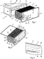
- the invention relates to a heat exchanger 1, in particular for supplying air to a heat engine of a motor vehicle, as here.
- the exchanger allows a heat exchange between a first fluid F1 and a second fluid F2.
- the first fluid F1 is a cooling liquid, in particular glycol water
- the second fluid F2 is the charge air, to be cooled.
- This exchanger 1 thus forms, for example, a charge air cooler integrated in an intake manifold 3 of the internal combustion engine.
- Said exchanger 1 comprises at least one heat exchange bundle 5 traversed by the first fluid F1 and a housing 7 in which said heat exchange bundle 5 is housed so as to be traversed by said second fluid F2.
- said heat exchanger 1 comprises at least one seal 9 disposed between said heat exchange bundle 5 and said housing 7 to limit the beam 5 being circumvented by the second fluid F2.
- the housing 7 is here configured to be connected to the intake pipes 11 of the engine. It includes in particular a prominence or outlet manifold13 on one of its large faces, by which it is connected to said intake pipes 11. A second fluid inlet manifold is located at the opposite side.
- Said housing 7 is closed on one of its faces by a plate known as a front flange 15, to which said heat exchange bundle 5 is fixed in leaktight manner, in particular by soldering.
- This front flange 15 is fixed here by screws 17 to the housing 7.
- Another sealing gasket may be used between said flange 15 and said housing 7 to prevent leakage of second fluid to the outside.
- Said flange 15 further comprises conduits 19 for entering and leaving the first fluid of the heat exchange bundle. It should be noted that this front flange 15 closes an opening 21 of the housing intended for the passage of the heat exchange bundle 5, during its mounting in the housing.
- Said heat exchange bundle 5 is here a rectangular parallelepiped. It comprises a stack of plates 23 alternately forming circulation channels for the first and the second fluid.
- the plates are, for example, assembled in pairs to form circulation channels for the first fluid.
- said channels are configured in a U and the first fluid enters and leaves pairs of plates at the orifices located on the same side 31 of the bundle 5.
- the orifices of the pairs of plates communicate with each other from pair to pair in order to form an inlet manifold and an outlet manifold for the first fluid, communicating respectively with the conduits 19 of the front flange 15.
- Said plates are formed, for example, by stamping, stacked and then brazed together.
- the heat exchange between the plates 23 and the second fluid takes place in part by means of turbulators 25 located between the pairs of plates.
- Said heat exchange bundle 5 is here closed on a large face, opposite said front flange 15, by a plate called structural plate 27.
- This plate 27 is for example fixed to the bundle by brazing.
- the plates 23 may each have a flange 29 formed projecting from their plane, in particular perpendicular to their plane.
- the rim 29 is here perpendicular to the lateral faces 31 of the bundle, namely the faces adjacent to the longitudinal faces 33 of air inlet and outlet of the bundle.
- This or these edges 29, particularly visible at figures 7 to 9 are preferably arranged in a plurality of identical flanges 29, regularly spaced from one another at the pairs of plates.
- the said edge (s) 29 are advantageously arranged along the same direction parallel to the stacking direction of the plates. They are located, for example, along an edge 35 of the longitudinal face 33 of the bundle, here the longitudinal exit face of the second fluid.
- said flanges 29 form a line d which is here an edge line 35 of said longitudinal face 33 of the outlet of the second fluid from the bundle.
- Said flanges 39 may be extended along said longitudinal face 33 in order to come into contact with the turbulators 25. They thus form a screen preventing the passage of the second fluid at the level of zones of the uncoated plates of said turbulators, which promotes exchange heat.
- Said structural cladding 27 also comprises at least one rim 37, here a regular rim 37, figure 10 , passing through a plane containing the said edge or edges 29 of the plates 23.
- This edge 37 is rectilinear, perpendicular to the plane of the structural plate 27.
- Said seal 9 is mounted along said one or more edges 29 of the bundle plate and of said flange 37 of the structural plate, by being fixed, for example glued, to the latter.
- said seal 9 is mounted on said flanges of the bundle plate and on said flange 37 of the structural plate, on three sides of the bundle 5, as here. It is notably configured with a U-shaped profile, Figures 7 and 8 , to extend longitudinally in continuity on said flanges 29 of the beam plate and said flange 37 of the plate structural, on each of said lateral faces 31 and structural plate 27 of the bundle.
- said seal 9 has a regular U-shaped section, figure 3 , able to allow the joint to engage on or receive said flange 29 of beam plate and said flange 37 of structural plate.
- the engagement can be relatively tight so as to retain the joint after the engagement.
- the profiles of the flanges 29 and 37 are identical here but they may be different, the seal 9 having a complementary profile.
- said seal 9 is capable of being fixed, in particular clipped by a hook 38 of the U, as it appears on the figure 5 , on said edge 29 of beam plate and said edge 37 of structural plate, after its engagement thereon.
- Said seal 9 comprises, Figures 9 and 10 , a profiled external lip 39, here according to a longitudinal profile of rounded section and tapered at the end 41.
- Said external lip 39 is suitable for being applied, in particular compressed, against a wall 43 of the housing, so as to impart said seal to the second fluid between the bundle and the housing.
- the seal 9 is housed in a profiled recess 45 of the housing, complementary to the seal.
- the recess 45 has here a rectangular section, which receives the seal 9, in particular in a compressed manner between two opposite lateral faces 47 of the recess.
- the seal 9 includes in particular a heel-shaped part 49 opposite of the lip 39, which allows it to hold the beam 5 securely to the housing 7.
- Said seal 9 is advantageously a thermoplastic or elastomer element, in particular deformable according to a certain tolerance to support said seal compression.
- This tolerance before and after compression is for example between 0.1 mm and 0.25 mm.
- said seal 9 is U-shaped to extend along said side faces 31 and the structural plate 27 of the bundle.
- the seal 9 is provided with a hinge zone 51, see the figures 6 and 7 , said two hinge zones 51 being able to increase the opening of the U when the joint is mounted on the bundle and to bring it back to its initial configuration of the U, when it engages on said flanges 29, 37.
- This arrangement facilitates the mounting of the attached to the harness.
- the seal can still be slid over the edges 29, figure 8 , until the engagement on the rim 37 at the end of assembly of the seal.
- Said housing 7 comprises a housing for said seal 9, which is here said recess 45.
- This housing 45 is shaped in a rib profile, in particular in said rectangular section, to allow sliding mounting, from the opening 21 , bundle 5 fitted with seal 9 in housing 7.
- Said housing 45 is shaped rigid to allow mechanical strength of the beam 5 in the housing 7, in particular by playing the role of stiffener. This arrangement makes it possible to remove the games and brings it to wrong in the connection of the beam to the housing and dampens vibrations. In this way, the modes of the vibration frequencies of the beam and thereby of the exchanger 1 are increased and the amplitudes of the vibrations in each mode are attenuated. The reliability of the exchanger and its silent operation are improved.
- Said bundle 5 is then fixed to the housing 7 by means of the front flange 15, here screwed onto an opening edge 21 of the housing.
- the invention also relates to a vehicle engine intake module 53 comprising a heat exchanger as described above and visible in part on figure 1 .
- the invention thus provides a heat exchanger, in particular a vehicle engine charge air cooler, which is efficient, quiet and reliable.
Landscapes
- Engineering & Computer Science (AREA)
- General Engineering & Computer Science (AREA)
- Mechanical Engineering (AREA)
- Physics & Mathematics (AREA)
- Thermal Sciences (AREA)
- Chemical & Material Sciences (AREA)
- Combustion & Propulsion (AREA)
- Geometry (AREA)
- Heat-Exchange Devices With Radiators And Conduit Assemblies (AREA)
Applications Claiming Priority (2)
| Application Number | Priority Date | Filing Date | Title |
|---|---|---|---|
| FR1453009A FR3019638B1 (fr) | 2014-04-04 | 2014-04-04 | Echangeur de chaleur pour vehicule automobile |
| PCT/EP2015/000724 WO2015149951A1 (fr) | 2014-04-04 | 2015-04-03 | Échangeur de chaleur pour véhicule automobile |
Publications (2)
| Publication Number | Publication Date |
|---|---|
| EP3134628A1 EP3134628A1 (fr) | 2017-03-01 |
| EP3134628B1 true EP3134628B1 (fr) | 2020-05-06 |
Family
ID=51063627
Family Applications (1)
| Application Number | Title | Priority Date | Filing Date |
|---|---|---|---|
| EP15723828.8A Active EP3134628B1 (fr) | 2014-04-04 | 2015-04-03 | Échangeur de chaleur pour véhicule automobile |
Country Status (9)
| Country | Link |
|---|---|
| US (1) | US20170023315A1 (pl) |
| EP (1) | EP3134628B1 (pl) |
| JP (1) | JP6383801B2 (pl) |
| KR (1) | KR101906698B1 (pl) |
| CN (1) | CN106414944B (pl) |
| ES (1) | ES2809514T3 (pl) |
| FR (1) | FR3019638B1 (pl) |
| PL (1) | PL3134628T3 (pl) |
| WO (1) | WO2015149951A1 (pl) |
Families Citing this family (10)
| Publication number | Priority date | Publication date | Assignee | Title |
|---|---|---|---|---|
| DE102013205316A1 (de) * | 2013-03-26 | 2014-10-02 | Behr Gmbh & Co. Kg | Frischluftanlage |
| FR3059727B1 (fr) * | 2016-12-07 | 2019-12-13 | Sogefi Air & Refroidissement France | Repartiteur d'admission avec un echangeur de chaleur integre |
| CN108278167A (zh) * | 2017-12-29 | 2018-07-13 | 重庆小康工业集团股份有限公司 | 内燃机进气歧管 |
| KR102436269B1 (ko) * | 2018-01-29 | 2022-08-26 | 한온시스템 주식회사 | 열교환기 |
| KR102021020B1 (ko) | 2018-10-23 | 2019-09-16 | 손성욱 | 대류식 열교환시스템 및 상기 대류식 열교환시스템을 이용하여 열교환하는 열교환방법 |
| KR20200082583A (ko) | 2018-12-31 | 2020-07-08 | 주식회사 엘솔컴퍼니 | 쿠키 데이터를 이용한 사용자 맞춤형 웹페이지 제어 방법 및 장치 |
| DE102019121494A1 (de) * | 2019-08-09 | 2021-02-11 | Mann+Hummel Gmbh | Wärmetauscheranordnung, Verfahren zur Herstellung einer Wärmetauscheranordnung und Brennkraftmaschine mit Wärmetauscheranordnung |
| KR20200045986A (ko) | 2019-12-17 | 2020-05-06 | 손성욱 | 냉기와 온기가 교차하면서 흡기와 배기가 이루어지는 대류식 열교환장치 |
| KR20210000290A (ko) | 2020-12-21 | 2021-01-04 | 손성욱 | 냉기와 온기가 교차하면서 흡기와 배기가 이루어지는 대류식 열교환장치 |
| FI130610B (en) * | 2021-12-21 | 2023-12-13 | Vahterus Oy | PLATE HEAT TRANSFER ARRANGEMENT, ITS USE IN FLUE GAS HEAT RECOVERY AND METHOD FOR RECOVERING HEAT FROM FLUE GAS |
Citations (1)
| Publication number | Priority date | Publication date | Assignee | Title |
|---|---|---|---|---|
| WO2012159730A1 (fr) * | 2011-05-26 | 2012-11-29 | Valeo Systemes Thermiques | Echangeur thermique, notamment pour vehicule automobile, et dispositif d'admission d'air correspondant |
Family Cites Families (14)
| Publication number | Priority date | Publication date | Assignee | Title |
|---|---|---|---|---|
| JPS5812063Y2 (ja) * | 1978-02-04 | 1983-03-07 | 株式会社クボタ | インサ−ト型空気冷却器 |
| DE4313505C2 (de) * | 1993-04-24 | 2002-02-07 | Mahle Filtersysteme Gmbh | Flüssigkeitskühler mit einem durchströmbaren Scheibenpaket |
| JPH0752637A (ja) * | 1993-08-16 | 1995-02-28 | Nippondenso Co Ltd | 空気調和装置 |
| DE102005039201A1 (de) * | 2005-08-18 | 2007-02-22 | Metzeler Automotive Profile Systems Gmbh | Dichtung, insbesondere für ein Kraftfahrzeug |
| DE102006005106A1 (de) * | 2006-02-04 | 2007-08-09 | Modine Manufacturing Co., Racine | Wärmetauscher mit einer Anschlussplatte, insbesondere Ladeluftkühler |
| US7921905B2 (en) * | 2006-06-29 | 2011-04-12 | Mahle International Gmbh | Plastic intercooler |
| JP2010127143A (ja) * | 2008-11-26 | 2010-06-10 | Calsonic Kansei Corp | チャージエアクーラ |
| FR2973445B1 (fr) * | 2011-03-31 | 2015-08-21 | Valeo Systemes Thermiques | Boitier repartiteur de gaz d'admission dans un moteur, notamment de vehicule automobile, et module d'alimentation en gaz comprenant ledit boitier |
| JP2012225311A (ja) * | 2011-04-21 | 2012-11-15 | Denso Corp | 吸気装置 |
| JP5598456B2 (ja) * | 2011-10-25 | 2014-10-01 | 株式会社デンソー | ガスケット |
| US20130133866A1 (en) * | 2011-11-28 | 2013-05-30 | Dana Canada Corporation | Heat Exchanger Plates with Integral Bypass Blocking Tabs |
| WO2013078531A1 (en) * | 2011-11-28 | 2013-06-06 | Dana Canada Corporation | Heat exchanger with end seal for blocking off air bypass flow |
| US20130133869A1 (en) * | 2011-11-28 | 2013-05-30 | Dana Canada Corporation | Heat Exchanger With End Seal For Blocking Off Air Bypass Flow |
| DE102013015179B4 (de) * | 2013-09-11 | 2026-02-05 | Modine Manufacturing Company | Wärmetauscheranordnung und Herstellungsverfahren |
-
2014
- 2014-04-04 FR FR1453009A patent/FR3019638B1/fr not_active Expired - Fee Related
-
2015
- 2015-04-03 EP EP15723828.8A patent/EP3134628B1/fr active Active
- 2015-04-03 US US15/301,596 patent/US20170023315A1/en not_active Abandoned
- 2015-04-03 JP JP2016560653A patent/JP6383801B2/ja not_active Expired - Fee Related
- 2015-04-03 PL PL15723828.8T patent/PL3134628T3/pl unknown
- 2015-04-03 KR KR1020167030887A patent/KR101906698B1/ko not_active Expired - Fee Related
- 2015-04-03 WO PCT/EP2015/000724 patent/WO2015149951A1/fr not_active Ceased
- 2015-04-03 ES ES15723828T patent/ES2809514T3/es active Active
- 2015-04-03 CN CN201580029710.XA patent/CN106414944B/zh active Active
Patent Citations (1)
| Publication number | Priority date | Publication date | Assignee | Title |
|---|---|---|---|---|
| WO2012159730A1 (fr) * | 2011-05-26 | 2012-11-29 | Valeo Systemes Thermiques | Echangeur thermique, notamment pour vehicule automobile, et dispositif d'admission d'air correspondant |
Also Published As
| Publication number | Publication date |
|---|---|
| CN106414944A (zh) | 2017-02-15 |
| CN106414944B (zh) | 2019-11-19 |
| PL3134628T3 (pl) | 2021-02-22 |
| FR3019638B1 (fr) | 2018-12-07 |
| WO2015149951A1 (fr) | 2015-10-08 |
| KR101906698B1 (ko) | 2018-10-10 |
| JP2017511460A (ja) | 2017-04-20 |
| FR3019638A1 (fr) | 2015-10-09 |
| JP6383801B2 (ja) | 2018-08-29 |
| US20170023315A1 (en) | 2017-01-26 |
| EP3134628A1 (fr) | 2017-03-01 |
| ES2809514T3 (es) | 2021-03-04 |
| KR20160134855A (ko) | 2016-11-23 |
Similar Documents
| Publication | Publication Date | Title |
|---|---|---|
| EP3134628B1 (fr) | Échangeur de chaleur pour véhicule automobile | |
| EP3132220B1 (fr) | Echangeur de chaleur pour véhicule automobile | |
| EP2715267B1 (fr) | Dispositif d'admission d'air avec échangeur thermique | |
| EP2726804B1 (fr) | Echangeur thermique notamment pour vehicule automobile | |
| EP2972049B1 (fr) | Echangeur thermique, en particulier refroidisseur d'air de suralimentation | |
| WO2008061850A1 (fr) | Dispositif d'echange de chaleur et dispositif d'admission de gaz comportant un tel dispositif | |
| FR2938051A1 (fr) | Unite d'echange thermique a usage par exemple dans un circuit de recirculation de gaz d'echappement | |
| FR2968753A1 (fr) | Echangeur de chaleur, notamment pour vehicule automobile | |
| EP2715264B1 (fr) | Echangeur thermique, notamment pour vehicule automobile, et dispositif d'admission d'air correspondant | |
| FR2972491A1 (fr) | Couvercle d'un boitier d'admission | |
| FR3015015A1 (fr) | Echangeur de chaleur comprenant un faisceau muni de moyens permettant de limiter les mouvements dudit faisceau d'echange par rapport aux parois du boitier | |
| EP3551953A1 (fr) | Echangeur de chaleur, notamment échangeur d'air de suralimentation pour véhicule automobile | |
| WO2016180474A1 (fr) | Connecteur fluidique pour échangeur thermique pour véhicule automobile | |
| EP3449198B1 (fr) | Collecteur et dispositif de refroidissement associe | |
| FR2935912A1 (fr) | Procede d'assemblage et de brasage de deux pieces munies d'elements d'assemblage. | |
| FR3000778A1 (fr) | Joint d'etancheite | |
| EP2469210B1 (fr) | Échangeur de chaleur à plaques empilées | |
| FR3030709A1 (fr) | Echangeur de chaleur | |
| FR2989768A1 (fr) | Echangeur de chaleur. | |
| EP3835701B1 (fr) | Échangeur double à flux de gaz orthogonaux | |
| FR3020454A1 (fr) | Connecteur fluidique pour echangeur thermique pour vehicule automobile | |
| FR2986312A1 (fr) | Echangeur thermique, tube plat et plaque correspondants | |
| FR2969271A1 (fr) | Boitier d'echangeur de chaleur, echangeur de chaleur muni d'un tel boitier et module d'admission equipe d'un tel echangeur | |
| WO2018138189A1 (fr) | Dispositif de distribution d'un flux d'air et d'un flux de gaz d'échappement recirculés et module d'admission d'air correspondant | |
| FR2924208A1 (fr) | Circulation alternee d'un fluide dans un echangeur thermique, bride de liaison de l'echangeur et module bride/echangeur correspondants |
Legal Events
| Date | Code | Title | Description |
|---|---|---|---|
| STAA | Information on the status of an ep patent application or granted ep patent |
Free format text: STATUS: THE INTERNATIONAL PUBLICATION HAS BEEN MADE |
|
| PUAI | Public reference made under article 153(3) epc to a published international application that has entered the european phase |
Free format text: ORIGINAL CODE: 0009012 |
|
| STAA | Information on the status of an ep patent application or granted ep patent |
Free format text: STATUS: REQUEST FOR EXAMINATION WAS MADE |
|
| 17P | Request for examination filed |
Effective date: 20161005 |
|
| AK | Designated contracting states |
Kind code of ref document: A1 Designated state(s): AL AT BE BG CH CY CZ DE DK EE ES FI FR GB GR HR HU IE IS IT LI LT LU LV MC MK MT NL NO PL PT RO RS SE SI SK SM TR |
|
| AX | Request for extension of the european patent |
Extension state: BA ME |
|
| DAV | Request for validation of the european patent (deleted) | ||
| DAX | Request for extension of the european patent (deleted) | ||
| STAA | Information on the status of an ep patent application or granted ep patent |
Free format text: STATUS: EXAMINATION IS IN PROGRESS |
|
| 17Q | First examination report despatched |
Effective date: 20190228 |
|
| GRAP | Despatch of communication of intention to grant a patent |
Free format text: ORIGINAL CODE: EPIDOSNIGR1 |
|
| STAA | Information on the status of an ep patent application or granted ep patent |
Free format text: STATUS: GRANT OF PATENT IS INTENDED |
|
| INTG | Intention to grant announced |
Effective date: 20191209 |
|
| GRAS | Grant fee paid |
Free format text: ORIGINAL CODE: EPIDOSNIGR3 |
|
| GRAA | (expected) grant |
Free format text: ORIGINAL CODE: 0009210 |
|
| STAA | Information on the status of an ep patent application or granted ep patent |
Free format text: STATUS: THE PATENT HAS BEEN GRANTED |
|
| AK | Designated contracting states |
Kind code of ref document: B1 Designated state(s): AL AT BE BG CH CY CZ DE DK EE ES FI FR GB GR HR HU IE IS IT LI LT LU LV MC MK MT NL NO PL PT RO RS SE SI SK SM TR |
|
| REG | Reference to a national code |
Ref country code: GB Ref legal event code: FG4D Free format text: NOT ENGLISH |
|
| REG | Reference to a national code |
Ref country code: CH Ref legal event code: EP Ref country code: AT Ref legal event code: REF Ref document number: 1267079 Country of ref document: AT Kind code of ref document: T Effective date: 20200515 |
|
| REG | Reference to a national code |
Ref country code: IE Ref legal event code: FG4D Free format text: LANGUAGE OF EP DOCUMENT: FRENCH |
|
| REG | Reference to a national code |
Ref country code: DE Ref legal event code: R096 Ref document number: 602015052175 Country of ref document: DE |
|
| REG | Reference to a national code |
Ref country code: LT Ref legal event code: MG4D |
|
| REG | Reference to a national code |
Ref country code: NL Ref legal event code: MP Effective date: 20200506 |
|
| PG25 | Lapsed in a contracting state [announced via postgrant information from national office to epo] |
Ref country code: PT Free format text: LAPSE BECAUSE OF FAILURE TO SUBMIT A TRANSLATION OF THE DESCRIPTION OR TO PAY THE FEE WITHIN THE PRESCRIBED TIME-LIMIT Effective date: 20200907 Ref country code: FI Free format text: LAPSE BECAUSE OF FAILURE TO SUBMIT A TRANSLATION OF THE DESCRIPTION OR TO PAY THE FEE WITHIN THE PRESCRIBED TIME-LIMIT Effective date: 20200506 Ref country code: NO Free format text: LAPSE BECAUSE OF FAILURE TO SUBMIT A TRANSLATION OF THE DESCRIPTION OR TO PAY THE FEE WITHIN THE PRESCRIBED TIME-LIMIT Effective date: 20200806 Ref country code: GR Free format text: LAPSE BECAUSE OF FAILURE TO SUBMIT A TRANSLATION OF THE DESCRIPTION OR TO PAY THE FEE WITHIN THE PRESCRIBED TIME-LIMIT Effective date: 20200807 Ref country code: SE Free format text: LAPSE BECAUSE OF FAILURE TO SUBMIT A TRANSLATION OF THE DESCRIPTION OR TO PAY THE FEE WITHIN THE PRESCRIBED TIME-LIMIT Effective date: 20200506 Ref country code: IS Free format text: LAPSE BECAUSE OF FAILURE TO SUBMIT A TRANSLATION OF THE DESCRIPTION OR TO PAY THE FEE WITHIN THE PRESCRIBED TIME-LIMIT Effective date: 20200906 Ref country code: LT Free format text: LAPSE BECAUSE OF FAILURE TO SUBMIT A TRANSLATION OF THE DESCRIPTION OR TO PAY THE FEE WITHIN THE PRESCRIBED TIME-LIMIT Effective date: 20200506 |
|
| PG25 | Lapsed in a contracting state [announced via postgrant information from national office to epo] |
Ref country code: BG Free format text: LAPSE BECAUSE OF FAILURE TO SUBMIT A TRANSLATION OF THE DESCRIPTION OR TO PAY THE FEE WITHIN THE PRESCRIBED TIME-LIMIT Effective date: 20200806 Ref country code: LV Free format text: LAPSE BECAUSE OF FAILURE TO SUBMIT A TRANSLATION OF THE DESCRIPTION OR TO PAY THE FEE WITHIN THE PRESCRIBED TIME-LIMIT Effective date: 20200506 Ref country code: HR Free format text: LAPSE BECAUSE OF FAILURE TO SUBMIT A TRANSLATION OF THE DESCRIPTION OR TO PAY THE FEE WITHIN THE PRESCRIBED TIME-LIMIT Effective date: 20200506 Ref country code: RS Free format text: LAPSE BECAUSE OF FAILURE TO SUBMIT A TRANSLATION OF THE DESCRIPTION OR TO PAY THE FEE WITHIN THE PRESCRIBED TIME-LIMIT Effective date: 20200506 |
|
| REG | Reference to a national code |
Ref country code: AT Ref legal event code: MK05 Ref document number: 1267079 Country of ref document: AT Kind code of ref document: T Effective date: 20200506 |
|
| PG25 | Lapsed in a contracting state [announced via postgrant information from national office to epo] |
Ref country code: NL Free format text: LAPSE BECAUSE OF FAILURE TO SUBMIT A TRANSLATION OF THE DESCRIPTION OR TO PAY THE FEE WITHIN THE PRESCRIBED TIME-LIMIT Effective date: 20200506 Ref country code: AL Free format text: LAPSE BECAUSE OF FAILURE TO SUBMIT A TRANSLATION OF THE DESCRIPTION OR TO PAY THE FEE WITHIN THE PRESCRIBED TIME-LIMIT Effective date: 20200506 |
|
| PG25 | Lapsed in a contracting state [announced via postgrant information from national office to epo] |
Ref country code: DK Free format text: LAPSE BECAUSE OF FAILURE TO SUBMIT A TRANSLATION OF THE DESCRIPTION OR TO PAY THE FEE WITHIN THE PRESCRIBED TIME-LIMIT Effective date: 20200506 Ref country code: SM Free format text: LAPSE BECAUSE OF FAILURE TO SUBMIT A TRANSLATION OF THE DESCRIPTION OR TO PAY THE FEE WITHIN THE PRESCRIBED TIME-LIMIT Effective date: 20200506 Ref country code: AT Free format text: LAPSE BECAUSE OF FAILURE TO SUBMIT A TRANSLATION OF THE DESCRIPTION OR TO PAY THE FEE WITHIN THE PRESCRIBED TIME-LIMIT Effective date: 20200506 Ref country code: EE Free format text: LAPSE BECAUSE OF FAILURE TO SUBMIT A TRANSLATION OF THE DESCRIPTION OR TO PAY THE FEE WITHIN THE PRESCRIBED TIME-LIMIT Effective date: 20200506 Ref country code: IT Free format text: LAPSE BECAUSE OF FAILURE TO SUBMIT A TRANSLATION OF THE DESCRIPTION OR TO PAY THE FEE WITHIN THE PRESCRIBED TIME-LIMIT Effective date: 20200506 Ref country code: RO Free format text: LAPSE BECAUSE OF FAILURE TO SUBMIT A TRANSLATION OF THE DESCRIPTION OR TO PAY THE FEE WITHIN THE PRESCRIBED TIME-LIMIT Effective date: 20200506 |
|
| REG | Reference to a national code |
Ref country code: DE Ref legal event code: R097 Ref document number: 602015052175 Country of ref document: DE |
|
| PG25 | Lapsed in a contracting state [announced via postgrant information from national office to epo] |
Ref country code: SK Free format text: LAPSE BECAUSE OF FAILURE TO SUBMIT A TRANSLATION OF THE DESCRIPTION OR TO PAY THE FEE WITHIN THE PRESCRIBED TIME-LIMIT Effective date: 20200506 |
|
| REG | Reference to a national code |
Ref country code: ES Ref legal event code: FG2A Ref document number: 2809514 Country of ref document: ES Kind code of ref document: T3 Effective date: 20210304 |
|
| PLBE | No opposition filed within time limit |
Free format text: ORIGINAL CODE: 0009261 |
|
| STAA | Information on the status of an ep patent application or granted ep patent |
Free format text: STATUS: NO OPPOSITION FILED WITHIN TIME LIMIT |
|
| 26N | No opposition filed |
Effective date: 20210209 |
|
| PG25 | Lapsed in a contracting state [announced via postgrant information from national office to epo] |
Ref country code: SI Free format text: LAPSE BECAUSE OF FAILURE TO SUBMIT A TRANSLATION OF THE DESCRIPTION OR TO PAY THE FEE WITHIN THE PRESCRIBED TIME-LIMIT Effective date: 20200506 |
|
| PGFP | Annual fee paid to national office [announced via postgrant information from national office to epo] |
Ref country code: ES Payment date: 20210506 Year of fee payment: 7 |
|
| PG25 | Lapsed in a contracting state [announced via postgrant information from national office to epo] |
Ref country code: MC Free format text: LAPSE BECAUSE OF FAILURE TO SUBMIT A TRANSLATION OF THE DESCRIPTION OR TO PAY THE FEE WITHIN THE PRESCRIBED TIME-LIMIT Effective date: 20200506 |
|
| GBPC | Gb: european patent ceased through non-payment of renewal fee |
Effective date: 20210403 |
|
| PG25 | Lapsed in a contracting state [announced via postgrant information from national office to epo] |
Ref country code: LU Free format text: LAPSE BECAUSE OF NON-PAYMENT OF DUE FEES Effective date: 20210403 |
|
| REG | Reference to a national code |
Ref country code: BE Ref legal event code: MM Effective date: 20210430 |
|
| PG25 | Lapsed in a contracting state [announced via postgrant information from national office to epo] |
Ref country code: CH Free format text: LAPSE BECAUSE OF NON-PAYMENT OF DUE FEES Effective date: 20210430 Ref country code: LI Free format text: LAPSE BECAUSE OF NON-PAYMENT OF DUE FEES Effective date: 20210430 Ref country code: GB Free format text: LAPSE BECAUSE OF NON-PAYMENT OF DUE FEES Effective date: 20210403 |
|
| PG25 | Lapsed in a contracting state [announced via postgrant information from national office to epo] |
Ref country code: IE Free format text: LAPSE BECAUSE OF NON-PAYMENT OF DUE FEES Effective date: 20210403 |
|
| PGFP | Annual fee paid to national office [announced via postgrant information from national office to epo] |
Ref country code: TR Payment date: 20220321 Year of fee payment: 8 Ref country code: PL Payment date: 20220328 Year of fee payment: 8 Ref country code: CZ Payment date: 20220322 Year of fee payment: 8 |
|
| PG25 | Lapsed in a contracting state [announced via postgrant information from national office to epo] |
Ref country code: BE Free format text: LAPSE BECAUSE OF NON-PAYMENT OF DUE FEES Effective date: 20210430 |
|
| REG | Reference to a national code |
Ref country code: ES Ref legal event code: FD2A Effective date: 20230526 |
|
| PG25 | Lapsed in a contracting state [announced via postgrant information from national office to epo] |
Ref country code: HU Free format text: LAPSE BECAUSE OF FAILURE TO SUBMIT A TRANSLATION OF THE DESCRIPTION OR TO PAY THE FEE WITHIN THE PRESCRIBED TIME-LIMIT; INVALID AB INITIO Effective date: 20150403 |
|
| PG25 | Lapsed in a contracting state [announced via postgrant information from national office to epo] |
Ref country code: CY Free format text: LAPSE BECAUSE OF FAILURE TO SUBMIT A TRANSLATION OF THE DESCRIPTION OR TO PAY THE FEE WITHIN THE PRESCRIBED TIME-LIMIT Effective date: 20200506 |
|
| P01 | Opt-out of the competence of the unified patent court (upc) registered |
Effective date: 20230528 |
|
| PG25 | Lapsed in a contracting state [announced via postgrant information from national office to epo] |
Ref country code: ES Free format text: LAPSE BECAUSE OF NON-PAYMENT OF DUE FEES Effective date: 20220404 |
|
| PG25 | Lapsed in a contracting state [announced via postgrant information from national office to epo] |
Ref country code: CZ Free format text: LAPSE BECAUSE OF NON-PAYMENT OF DUE FEES Effective date: 20230403 |
|
| PG25 | Lapsed in a contracting state [announced via postgrant information from national office to epo] |
Ref country code: MK Free format text: LAPSE BECAUSE OF FAILURE TO SUBMIT A TRANSLATION OF THE DESCRIPTION OR TO PAY THE FEE WITHIN THE PRESCRIBED TIME-LIMIT Effective date: 20200506 |
|
| PG25 | Lapsed in a contracting state [announced via postgrant information from national office to epo] |
Ref country code: MT Free format text: LAPSE BECAUSE OF FAILURE TO SUBMIT A TRANSLATION OF THE DESCRIPTION OR TO PAY THE FEE WITHIN THE PRESCRIBED TIME-LIMIT Effective date: 20200506 |
|
| PG25 | Lapsed in a contracting state [announced via postgrant information from national office to epo] |
Ref country code: PL Free format text: LAPSE BECAUSE OF NON-PAYMENT OF DUE FEES Effective date: 20230403 |
|
| PG25 | Lapsed in a contracting state [announced via postgrant information from national office to epo] |
Ref country code: PL Free format text: LAPSE BECAUSE OF NON-PAYMENT OF DUE FEES Effective date: 20230403 |
|
| PGFP | Annual fee paid to national office [announced via postgrant information from national office to epo] |
Ref country code: DE Payment date: 20250411 Year of fee payment: 11 |
|
| PGFP | Annual fee paid to national office [announced via postgrant information from national office to epo] |
Ref country code: FR Payment date: 20250429 Year of fee payment: 11 |