EP3133685B1 - Gaskanalformungsplatte für brennstoffzelle und brennstoffzellenstapel - Google Patents
Gaskanalformungsplatte für brennstoffzelle und brennstoffzellenstapel Download PDFInfo
- Publication number
- EP3133685B1 EP3133685B1 EP16182066.7A EP16182066A EP3133685B1 EP 3133685 B1 EP3133685 B1 EP 3133685B1 EP 16182066 A EP16182066 A EP 16182066A EP 3133685 B1 EP3133685 B1 EP 3133685B1
- Authority
- EP
- European Patent Office
- Prior art keywords
- gas
- electrode assembly
- membrane electrode
- slit
- water
- Prior art date
- Legal status (The legal status is an assumption and is not a legal conclusion. Google has not performed a legal analysis and makes no representation as to the accuracy of the status listed.)
- Active
Links
Images




Classifications
-
- H—ELECTRICITY
- H01—ELECTRIC ELEMENTS
- H01M—PROCESSES OR MEANS, e.g. BATTERIES, FOR THE DIRECT CONVERSION OF CHEMICAL ENERGY INTO ELECTRICAL ENERGY
- H01M8/00—Fuel cells; Manufacture thereof
- H01M8/02—Details
- H01M8/0202—Collectors; Separators, e.g. bipolar separators; Interconnectors
- H01M8/0258—Collectors; Separators, e.g. bipolar separators; Interconnectors characterised by the configuration of channels, e.g. by the flow field of the reactant or coolant
- H01M8/026—Collectors; Separators, e.g. bipolar separators; Interconnectors characterised by the configuration of channels, e.g. by the flow field of the reactant or coolant characterised by grooves, e.g. their pitch or depth
-
- H—ELECTRICITY
- H01—ELECTRIC ELEMENTS
- H01M—PROCESSES OR MEANS, e.g. BATTERIES, FOR THE DIRECT CONVERSION OF CHEMICAL ENERGY INTO ELECTRICAL ENERGY
- H01M8/00—Fuel cells; Manufacture thereof
- H01M8/02—Details
- H01M8/0202—Collectors; Separators, e.g. bipolar separators; Interconnectors
-
- H—ELECTRICITY
- H01—ELECTRIC ELEMENTS
- H01M—PROCESSES OR MEANS, e.g. BATTERIES, FOR THE DIRECT CONVERSION OF CHEMICAL ENERGY INTO ELECTRICAL ENERGY
- H01M8/00—Fuel cells; Manufacture thereof
- H01M8/02—Details
- H01M8/0202—Collectors; Separators, e.g. bipolar separators; Interconnectors
- H01M8/0247—Collectors; Separators, e.g. bipolar separators; Interconnectors characterised by the form
- H01M8/0254—Collectors; Separators, e.g. bipolar separators; Interconnectors characterised by the form corrugated or undulated
-
- H—ELECTRICITY
- H01—ELECTRIC ELEMENTS
- H01M—PROCESSES OR MEANS, e.g. BATTERIES, FOR THE DIRECT CONVERSION OF CHEMICAL ENERGY INTO ELECTRICAL ENERGY
- H01M8/00—Fuel cells; Manufacture thereof
- H01M8/02—Details
- H01M8/0202—Collectors; Separators, e.g. bipolar separators; Interconnectors
- H01M8/0247—Collectors; Separators, e.g. bipolar separators; Interconnectors characterised by the form
- H01M8/0256—Vias, i.e. connectors passing through the separator material
-
- H—ELECTRICITY
- H01—ELECTRIC ELEMENTS
- H01M—PROCESSES OR MEANS, e.g. BATTERIES, FOR THE DIRECT CONVERSION OF CHEMICAL ENERGY INTO ELECTRICAL ENERGY
- H01M8/00—Fuel cells; Manufacture thereof
- H01M8/02—Details
- H01M8/0202—Collectors; Separators, e.g. bipolar separators; Interconnectors
- H01M8/0258—Collectors; Separators, e.g. bipolar separators; Interconnectors characterised by the configuration of channels, e.g. by the flow field of the reactant or coolant
-
- H—ELECTRICITY
- H01—ELECTRIC ELEMENTS
- H01M—PROCESSES OR MEANS, e.g. BATTERIES, FOR THE DIRECT CONVERSION OF CHEMICAL ENERGY INTO ELECTRICAL ENERGY
- H01M8/00—Fuel cells; Manufacture thereof
- H01M8/02—Details
- H01M8/0202—Collectors; Separators, e.g. bipolar separators; Interconnectors
- H01M8/0258—Collectors; Separators, e.g. bipolar separators; Interconnectors characterised by the configuration of channels, e.g. by the flow field of the reactant or coolant
- H01M8/0265—Collectors; Separators, e.g. bipolar separators; Interconnectors characterised by the configuration of channels, e.g. by the flow field of the reactant or coolant the reactant or coolant channels having varying cross sections
-
- H—ELECTRICITY
- H01—ELECTRIC ELEMENTS
- H01M—PROCESSES OR MEANS, e.g. BATTERIES, FOR THE DIRECT CONVERSION OF CHEMICAL ENERGY INTO ELECTRICAL ENERGY
- H01M8/00—Fuel cells; Manufacture thereof
- H01M8/04—Auxiliary arrangements, e.g. for control of pressure or for circulation of fluids
- H01M8/04082—Arrangements for control of reactant parameters, e.g. pressure or concentration
- H01M8/04089—Arrangements for control of reactant parameters, e.g. pressure or concentration of gaseous reactants
- H01M8/04119—Arrangements for control of reactant parameters, e.g. pressure or concentration of gaseous reactants with simultaneous supply or evacuation of electrolyte; Humidifying or dehumidifying
- H01M8/04156—Arrangements for control of reactant parameters, e.g. pressure or concentration of gaseous reactants with simultaneous supply or evacuation of electrolyte; Humidifying or dehumidifying with product water removal
-
- H—ELECTRICITY
- H01—ELECTRIC ELEMENTS
- H01M—PROCESSES OR MEANS, e.g. BATTERIES, FOR THE DIRECT CONVERSION OF CHEMICAL ENERGY INTO ELECTRICAL ENERGY
- H01M8/00—Fuel cells; Manufacture thereof
- H01M8/24—Grouping of fuel cells, e.g. stacking of fuel cells
- H01M8/241—Grouping of fuel cells, e.g. stacking of fuel cells with solid or matrix-supported electrolytes
-
- H—ELECTRICITY
- H01—ELECTRIC ELEMENTS
- H01M—PROCESSES OR MEANS, e.g. BATTERIES, FOR THE DIRECT CONVERSION OF CHEMICAL ENERGY INTO ELECTRICAL ENERGY
- H01M8/00—Fuel cells; Manufacture thereof
- H01M8/24—Grouping of fuel cells, e.g. stacking of fuel cells
- H01M8/2457—Grouping of fuel cells, e.g. stacking of fuel cells with both reactants being gaseous or vaporised
-
- H—ELECTRICITY
- H01—ELECTRIC ELEMENTS
- H01M—PROCESSES OR MEANS, e.g. BATTERIES, FOR THE DIRECT CONVERSION OF CHEMICAL ENERGY INTO ELECTRICAL ENERGY
- H01M8/00—Fuel cells; Manufacture thereof
- H01M8/10—Fuel cells with solid electrolytes
- H01M2008/1095—Fuel cells with polymeric electrolytes
-
- H—ELECTRICITY
- H01—ELECTRIC ELEMENTS
- H01M—PROCESSES OR MEANS, e.g. BATTERIES, FOR THE DIRECT CONVERSION OF CHEMICAL ENERGY INTO ELECTRICAL ENERGY
- H01M8/00—Fuel cells; Manufacture thereof
- H01M8/02—Details
- H01M8/0202—Collectors; Separators, e.g. bipolar separators; Interconnectors
- H01M8/0204—Non-porous and characterised by the material
- H01M8/0206—Metals or alloys
-
- H—ELECTRICITY
- H01—ELECTRIC ELEMENTS
- H01M—PROCESSES OR MEANS, e.g. BATTERIES, FOR THE DIRECT CONVERSION OF CHEMICAL ENERGY INTO ELECTRICAL ENERGY
- H01M8/00—Fuel cells; Manufacture thereof
- H01M8/02—Details
- H01M8/0202—Collectors; Separators, e.g. bipolar separators; Interconnectors
- H01M8/0204—Non-porous and characterised by the material
- H01M8/0206—Metals or alloys
- H01M8/0208—Alloys
- H01M8/021—Alloys based on iron
-
- Y—GENERAL TAGGING OF NEW TECHNOLOGICAL DEVELOPMENTS; GENERAL TAGGING OF CROSS-SECTIONAL TECHNOLOGIES SPANNING OVER SEVERAL SECTIONS OF THE IPC; TECHNICAL SUBJECTS COVERED BY FORMER USPC CROSS-REFERENCE ART COLLECTIONS [XRACs] AND DIGESTS
- Y02—TECHNOLOGIES OR APPLICATIONS FOR MITIGATION OR ADAPTATION AGAINST CLIMATE CHANGE
- Y02E—REDUCTION OF GREENHOUSE GAS [GHG] EMISSIONS, RELATED TO ENERGY GENERATION, TRANSMISSION OR DISTRIBUTION
- Y02E60/00—Enabling technologies; Technologies with a potential or indirect contribution to GHG emissions mitigation
- Y02E60/30—Hydrogen technology
- Y02E60/50—Fuel cells
Definitions
- the present invention relates to a gas channel forming plate that is arranged between a membrane electrode assembly and a plate-shaped flat separator and constitutes a separator of a single cell in a fuel cell, and to a fuel cell stack formed by stacking single cells.
- a solid polymer fuel cell includes a fuel cell stack, which is formed by stacking single cells.
- Each single cell includes a membrane electrode assembly and a pair of separators. The membrane electrode assembly is placed between the separators.
- a separator including a plate-shaped flat separator and a gas channel forming plate that is arranged between a membrane electrode assembly and the flat separator (for example, refer to Japanese Laid-Open Patent Publication No. 2015-15218 ).
- Grooves that extend parallel with each other are formed on a surface of the gas channel forming plate that faces the membrane electrode assembly.
- the grooves constitute gas channels, through which fuel gas or oxidant gas flows.
- the gas channel forming plate includes protrusions that are each formed between the corresponding adjacent pair of gas channels.
- grooves are formed on the back surfaces of the protrusions.
- the grooves constitute water channels for discharging water produced during power generation.
- the projections include communication passages through which the gas channels communicate with water channels and water in the gas channels is introduced to the water channels using capillary action.
- water produced during power generation in the membrane electrode assembly flows out to the gas channels of the gas channel forming plate and is introduced to the water channels through the communication passages.
- the water is then discharged to the exterior of the water channels by the flow pressure of fuel gas or oxidant gas (hereinafter, referred to as gas) that flows through the water channels.
- gas fuel gas or oxidant gas
- a gas channel forming plate for a fuel cell which has a corrugated cross section and is arranged between a membrane electrode assembly and a plate-shaped flat separator to constitute a separator of a single cell of a fuel cell.
- Fuel gas and oxidant gas are supplied to the membrane electrode assembly to generate power and produce water.
- the gas channel forming plate includes a surface that faces the membrane electrode assembly, a plurality of protrusions that is formed on the surface and extends parallel with each other in an extending direction, a plurality of groove-shaped gas channels, each of which is located between an adjacent pair of the protrusions, and a plurality of groove-shaped water channels, each of which is formed on a back surface of one of the protrusions.
- Each protrusion includes a plurality of communication portions, which is formed to be separated from each other in the extending direction.
- Each communication portion includes a slit, which constitutes an opening that opens in the surface facing the membrane electrode assembly, and a rib, which is located inside the corresponding water channel and faces the slit.
- the communication portions of each protrusion are configured to allow at least one gas channel adjacent to the protrusion to communicate with a water channel on a back side of the protrusion and to introduce water in the at least one gas channel adjacent to the protrusion to the water channel on the back side of the protrusion using capillary action.
- the communication portions include a plurality of first communication portions and a plurality of second communication portions, which is located upstream of the first communication portions in a flowing direction of gas.
- Each first communication portion includes a first opening, which opens in the surface that faces the membrane electrode assembly.
- Each second communication portion includes a second opening, which opens in the surface that faces the membrane electrode assembly.
- Each first communication portion includes a first slit, which constitutes the first opening of the first communication portion, and a first rib, which is located inside the corresponding water channel and faces the first slit.
- Each second communication portion includes a second slit, which constitutes the second opening of the second communication portion, and a second rib, which is located inside the corresponding water channel and faces the second slit.
- the second communication portions of each protrusion constitute an expanding region, in which an opening area of the second opening in each second communication portion is greater than an opening area of the first opening of each first communication portion, to limit introduction of water to the water channel on the back side of the protrusion using capillary action by the second communication portions.
- the first slit of each first communication portion extends perpendicular to the extending direction, and has a predetermined width
- the second slit of each second communication portion which extends perpendicular to the extending direction, and has a predetermined width.
- the predetermined width of the second slit is set to be greater than the predetermined width of the first slit.
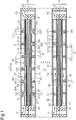
- a solid polymer electrolyte fuel cell includes a fuel cell stack formed by stacking single cells 10.
- the single cell 10 on the upper side in Fig. 1 has a cross-section taken along such a line that first and second water channels 26 and 36, which will be described later, are visible while the single cell 10 on the lower side has a cross-section taken along such a line that first and second gas channels 25 and 35, which will be described later, are visible.
- Each single cell 10 includes a rectangular first frame 11 and second frame 12.
- the first and second frames 11 and 12 hold the outer edge of a rectangular sheet-shaped membrane electrode assembly 13 of a known type in between.
- the membrane electrode assembly 13 includes a solid polymer electrolyte membrane 14.
- First and second electrode catalyst layers 15 and 16 of a known type hold the solid polymer electrolyte membrane 14 in between.
- First and second gas diffusion layers 17 and 18 of a known type are arranged on the surfaces of the first and second electrode catalyst layers 15 and 16, respectively.
- a first separator 20 and a second separator 30 sandwich the membrane electrode assembly 13 from the cathode-side (the lower side of Fig. 1 ) and the anode-side (the upper side of Fig. 1 ), respectively.
- the first separator 20 includes a plate-shaped first flat separator 21 and a first gas channel forming plate 22, which is arranged between the first flat separator 21 and the membrane electrode assembly 13.
- the second separator 30 includes a plate-shaped second flat separator 31 and a second gas channel forming plate 32, which is arranged between the second flat separator 31 and the membrane electrode assembly 13.
- the flat separators 21 and 31 and the gas channel forming plates 22 and 32 are each formed of a metal plate.
- the first frame 11 and the first flat separator 21 define a first supply passage 41 for supplying oxidant gas from an oxidant gas supply source (not shown) to a first gas channel 25, which will be described later, and a first discharge passage 42 for discharging oxidant gas that has not been used for power generation to the exterior of the first gas channel 25.
- the second frame 12 and the second flat separator 31 define a second supply passage 51 for supplying fuel gas from a fuel gas supply source (not shown) to a second gas channel 35, which will be described later, and a second discharge passage 52 for discharging fuel gas that has not been used for power generation to the exterior of the second gas channel 35.
- the second gas channel forming plate 32 of the second separator 30 has a shape obtained by inverting the first gas channel forming plate 22 of the first separator 20 vertically and horizontally.
- the first gas channel forming plate 22 of the first separator 20 will be described, and the repetitive description of the second gas channel forming plate 32 of the second separator 30 will be omitted by giving reference numerals "3*", which are obtained by adding 10 to reference numerals "2*" of components of the first gas channel forming plate 22 of the first separator 20, to corresponding components of the second gas channel forming plate 32 of the second separator 30.
- the repetitive description will be omitted by giving reference numerals "37*" and "38*,” which are obtained by adding 100 to reference numerals "27*" and "28*.”
- the sign * indicates one of numbers from zero to nine.
- the first gas channel forming plate 22 has a corrugated cross section and is formed by, e.g., rolling one metal plate such as a stainless steel plate.
- Inner protrusions 23, which extend parallel with each other, are formed on the upper surface of the first gas channel forming plate 22, i.e., the surface of the first gas channel forming plate that faces the membrane electrode assembly 13.
- the top surfaces of the inner protrusions 23 are in contact with the membrane electrode assembly 13.
- a groove-shaped first gas channel 25, through which oxidant gas flows, is formed between each adjacent pair of inner protrusions 23.
- the top surfaces of the outer protrusions 24 are in contact with the flat separator 21.
- a groove-shaped first water channel 26 for discharging water produced during power generation in the membrane electrode assembly 13 is formed on the back surface of each inner protrusion 23.
- each outer protrusion 24 is located between the corresponding adjacent pair of first water channels 26 and defines the water channels 26.
- Each inner protrusion 23 includes first and second communication portions 27 and 28, which allow the corresponding first gas channel 25 and first water channel 26 to communicate with each other, in the extending direction L of the inner protrusions 23.
- each first communication portion 27 is located downstream of the second communication portions 28 in the flowing direction of gas.
- Each first communication portion 27 includes two first slits 271, which are formed at a predetermined interval L1 in the extending direction L of the inner protrusions 23.
- Each first slit 271 extends perpendicular to the extending direction L of the inner protrusions 23 and has a preset width A1.
- the width A1 of each first slit 271 is set to have a measurement that allows water in the corresponding first gas channel 25 to be introduced to the corresponding first water channel 26 using capillary action.
- first ribs 272 (first intermediate structure portions), which face the first slits 271, are formed inside each first water channel 26.
- the first ribs 272 extend in the direction perpendicular to the extending direction L of the inner protrusions 23 (hereinafter, referred to as a width direction W).
- Each first rib 272 is formed by shear-bending a part of the corresponding inner protrusion 23 when a metal plate is rolled in the width direction W to form the first gas channel forming plate 22.
- each first slit 271 is formed by forming the corresponding first rib 272.
- each first rib 272 is located inside the corresponding first water channel 26.
- each outer protrusion 24 includes communication grooves 273, which allows the corresponding pair of first water channels 26 that is adjacent to each other via the outer protrusion 24 to communicate with each other.
- each inner protrusion 23 the first communication portions 27 are formed at intervals L3 in the extending direction L of the inner protrusions 23.
- the interval L3 between each adjacent pair of first communication portions 27 is set to be greater than the interval L1 between each pair of first slits 271 of the first communication portions 27 (L3 > L1).
- each first communication portion 27 of each inner protrusion 23 is located in the middle point between the corresponding adjacent pair of first communication portions 27 of an adjacent inner protrusion 23.
- the second communication portions 28 are located upstream of the first communication portions 27 in the flowing direction of gas.
- Each second communication portion 28 includes a pair of second slits 281, which is formed at a predetermined interval L2, in the extending direction L of the inner protrusions 23.
- Each second slit 281 extends perpendicular to the extending direction L of the inner protrusions 23 and has a preset width A2.
- the width A2 of each second slit 281 is set to be greater than width A1 of each first slit 271 of the first communication portions 27 (A2 > A1).
- each first slit 271 constitutes a first opening that opens in the surface that faces the membrane electrode assembly 13 (the upper surface) in the corresponding first communication portion 27.
- Each second slit 281 constitutes a second opening that opens in the surface that faces the membrane electrode assembly 13 (the upper surface) in the corresponding second communication portion 28.
- the opening area of each second opening of the second communication portions 28 is expanded to be greater than the opening area of each first opening of the first communication portions 27.
- the second communication portions 28, which are located upstream in the flowing direction of gas, constitute an expanding region, in which the opening area of the second openings that open in the surface that faces the membrane electrode assembly 13 of each second communication portion 28 is greater than the opening area of the first openings of each first communication portion 27, which are located downstream in the flowing direction of gas.
- Second ribs 282 (second intermediate structure portions), which face the second slits 281, are formed inside each first water channel 26.
- the second ribs 282 are formed in a method similar to the first ribs 272 of the first communication portions 27.
- a partition 284 between each pair of the second slits 281 that constitutes the corresponding second communication portion 28 in the corresponding inner protrusion 23 is located inside the corresponding first water channel 26.
- each inner protrusion 23 the second communication portions 28 are formed at a predetermined interval L4 in the extending direction L of the inner protrusions 23.
- the interval L4 of each adjacent pair of second communication portions 28 is set to be greater than the interval L2 between each pair of second slits 281 of the second communication portions 28 (L4 > L2).
- each second communication portion 28 of each inner protrusion 23 is located in the middle point between the corresponding adjacent pair of second communication portions 28 of an adjacent inner protrusion 23.
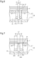
- the first and second ribs 272 and 282 of the first and second communication portions 27 and 28 are arranged closer to the top surfaces of the outer protrusions 24 than the top surfaces of the inner protrusions 23 in the thickness direction of the first gas channel forming plate 22 (the vertical direction of Figs. 4A, 4B , 6, and 7 ). Even when the cross-sectional area of each first gas channel 25 and the cross-sectional area of each first water channel 26 at a location at which the first and second ribs 272 and 282 do not exist in the extending direction L are set to be the same as each other, the pressure loss in the entire first water channel 26 is greater than the pressure loss in the entire first gas channel 25 due to the first and second ribs 272 and 282.
- the shapes and sizes of the first and second slits 271 and 281 are set such that the pressure loss at the first and second slits 271 and 281 is greater than the pressure loss in the first gas channel 25. Therefore, oxidant gas mainly flows through the first gas channel 25 with smaller pressure loss.
- each first gas channel 25 through the first supply passage 41 When oxidant gas is supplied into each first gas channel 25 through the first supply passage 41, the oxidant gas flows into the first gas diffusion layer 17 through the first gas channel 25. The oxidant gas is then supplied to the first electrode catalyst layer 15 by passing through the first gas diffusion layer 17 and being diffused.
- water produced during power generation mainly flows out to the first gas channel 25 of the first gas channel forming plate 22 on the cathode-side.
- Figs. 8A and 8B some of the water produced during power generation flows in each first gas channel 25 by flow pressure of oxidant gas flowing through the first gas channel 25.
- the water is then discharged to the exterior through the first discharge passage 42 (refer to Fig. 1 ).
- the pressure loss at the slits 271 (281) is set to be greater than the pressure loss at the first gas channels 25.
- the oxidant gas mainly flows through the first gas channels 25. This causes most of the water that exists in the first gas channels 25 to move in the first gas channels 25 toward the first discharge passage 42 while being pushed by the oxidant gas.
- some of the water is introduced to a first water channel 26 through the corresponding slits 271(281).
- the water that has been introduced to the first water channel 26 becomes droplets by surface tension acting according to the opening area of the exit opening of the first water channel 26.
- water in the first water channel 26 acts as priming water to guide the water in the corresponding first slits 271 into the first water channel 26 by capillary action and discharge the water through the exit opening.
- the droplets S1 and S2 are merged to form one droplet S3.
- the droplet S3 contacts the first ribs 272.
- the droplet S3 moves into the gap between the pair of first ribs 272 as shown in Fig. 9C
- the droplet S3 is introduced into the first water channel 26 by being drawn into the gap by capillary action as shown in Fig. 9D .
- each first gas channel 25 dry oxidant gas is introduced into each first gas channel 25.
- a portion of the membrane electrode assembly 13 that is close to the entrance of the first gas channel 25 is likely to be dried.
- the amount of water produced during power generation in the membrane electrode assembly 13 is decreased.
- the membrane electrode assembly 13 is more likely to be dried.
- introduction of water to the first water channel 26 using capillary action by the second communication portions 28 is restrained by increasing the opening areas of the second communication portions 28 in the expanding region formed upstream in the flowing direction of gas. This limits drying of the upstream portion of the membrane electrode assembly 13, which is likely to be dried. Thus, the membrane electrode assembly 13 can be kept moist to promote movement of protons.
- first gas channels 25 In a region downstream of the expanding region, water in the first gas channels 25 is effectively introduced to the respective first water channels 26 using capillary action by first communication portions 27. This restricts the flow of gas from being hampered by water staying in the first gas channels 25.
- water in the first gas channels 25 is also introduced to the first water channels 26 using capillary action by the second communication portions 28 in the expanding region. This restricts the flow of gas from being hampered by water staying in the first gas channels 25.
- the second gas channel forming plate 32 on the anode-side has basically the same configuration as the first gas channel forming plates 22 on the cathode-side.
- the second gas channels 35 and the second water channels 36 on the anode-side also provide the same operation as the first gas channels 25 and the first water channels 26 on the cathode-side.
- the gas channel forming plate for a fuel cell and the fuel cell stack according to the present embodiment which is described above, achieves the following advantages.
- Such a configuration limits drying of an upstream portion of the membrane electrode assembly 13, which is easily dried. This allows the membrane electrode assembly 13 to be kept moist, and the movement of protons is promoted.
- water in the first gas channel 25 is effectively introduced to the first water channel 26 using capillary action by the first communication portions 27.
- water in the first gas channel 25 is also introduced to the first water channel 26 in the expanding region using capillary action by the second communication portions 28. This restricts the flow of gas from being hampered by water staying in the first gas channel 25.
- each second communication portion 28 of each inner protrusion 23 the second openings of the pair of second slits 281 are connected to each other by locating the partition 284 between the pair of second slits 281 inside the corresponding water channel 26.
- This increases the opening area of the second communication portion 28, allowing the opening area to be easily expanded to be larger than the area of the first openings of each first communication portion 27. Accordingly, the configuration allows the opening area of the second communication portion 28 to be increased without increasing the widths of the second slits 281 so much.
- the first and second gas channel forming plates 22 and 32 may be formed of a metal plate other than a stainless plate such as a titanium plate.
- each second communication portion 28 may be formed to be the same height as the second ribs 282.
- the partition 284 and the second ribs 282 may be integrated.
- each partition 284 of the second communication portions 28 does not necessarily need to be located in the corresponding first water channel 26.
- the partition 284 may be formed to have the same height as the top surface of the corresponding inner protrusion 23. This modification also allows the opening area of the second openings, which open in the surface that faces the membrane electrode assembly 13, to be increased by setting the width A2 of each second slit 281 larger than the width A1 of each first slit 271 of the first communication portions 27.
- each second slit 281 of the second communication portions 28 may be set to be the same as the width A1 of each first slit 271 of the first communication portions 27. Even in this case, the second openings of each pair of second slits 281 are connected to each other to increase the opening area of the corresponding second communication portion 28 by locating the corresponding partition 284 inside the corresponding first water channel 26.
- the number of slits that constitute a communication portion is not limited to two. In other words, one slit may constitute a communication portion, or three or more slits may constitute a communication portion.
- the first and second ribs 272 and 282 may be omitted.
- the first and second ribs 372 and 382 may be omitted.
- the first and second gas channel forming plates 22 and 32 having expanding regions are arranged on both the cathode-side and the anode-side of the membrane electrode assembly 13.
- a gas channel forming plate with an expanding region may be arranged only on the cathode-side of the membrane electrode assembly 13, and a gas channel forming plate without an expanding region may be arranged on the anode-side.
- a gas channel forming plate with an expanding region may be arranged only on the anode-side of the membrane electrode assembly 13, and a gas channel forming plate without an expanding region may be arranged on the cathode-side.
Landscapes
- Life Sciences & Earth Sciences (AREA)
- Engineering & Computer Science (AREA)
- Manufacturing & Machinery (AREA)
- Sustainable Development (AREA)
- Sustainable Energy (AREA)
- Chemical & Material Sciences (AREA)
- Chemical Kinetics & Catalysis (AREA)
- Electrochemistry (AREA)
- General Chemical & Material Sciences (AREA)
- Fuel Cell (AREA)
Claims (3)
- Gaskanalformungsplatte für eine Brennstoffzelle, die einen gewellten Querschnitt aufweist und zwischen einer Membranelektronenanordnung (13) und einem plattenförmigen flachen Separator (21, 31) angeordnet ist, um einen Separator einer einzelnen Zelle (10) einer Brennstoffzelle zu bilden, wobei Brenngas und Oxidationsgas der Membranelektronenanordnung (13) zugeführt werden, um Energie zu generieren und Wasser zu erzeugen, wobei die Gaskanalformungsplatte umfasst:eine Fläche, die der Membranelektronenanordnung (13) zugewandt ist;mehrere Vorsprünge (23, 33), die auf der Fläche gebildet ist und sich parallel zueinander in einer Ausdehnungsrichtung erstreckt;mehrere rillenförmige Gaskanäle (25, 35), von denen jeder zwischen einem benachbarten Paar von Vorsprüngen (23, 33) angeordnet ist, wobei eines von dem Brenngas und dem Oxidationsgas in die Membranelektrodenanordnung (13) durch die Gaskanäle (25, 35) strömt und das während der Energiegenerierung in der Membranelektrodenanordnung (13) erzeugte Wasser aus den Gaskanälen (25, 35) strömt; undmehrere rillenförmige Wasserkanäle (26, 36), von denen jeder auf einer hinteren Fläche eines der Vorsprünge (23, 33) gebildet ist, wobeijeder Vorsprung (23, 33) mehrere Kommunikationsabschnitte (27, 28, 37, 38) aufweist, die gebildet ist, um voneinander in der Ausdehnungsrichtung (L) getrennt zu sein,wobei jeder Kommunikationsabschnitt (27, 28, 37, 38) einen Schlitz (271, 281, 371, 381) aufweist, der eine Öffnung bildet, welche sich in der Fläche öffnet, die der Membranelektrodenanordnung (13) zugewandt ist, und eine Rippe (272, 282, 372, 382), die innerhalb des entsprechenden Wasserkanals (26, 36) angeordnet ist und dem Schlitz (271, 281, 371, 381) zugewandt ist, unddie Kommunikationsabschnitte (27, 28, 37, 38) jedes Vorsprungs (23, 33) ausgelegt sind, es mindestens einem Gaskanal (25, 35) benachbart dem Vorsprung (23, 33) zu gestatten, mit einem Wasserkanal (26, 36) auf einer hinteren Fläche des Vorsprungs (23, 33) zu kommunizieren und Wasser in den mindestens einen Gaskanal (25, 35) benachbart dem Vorsprung (23, 33) in den Wasserkanal (26, 36) auf der hinteren Fläche des Vorsprungs (23, 33) unter Verwendung einer Kapillarwirkung einzuführen,wobei die Gaskanalformungsplatte dadurch gekennzeichnet, dass:die Kommunikationsabschnitte (27, 28, 37, 38) jedes Vorsprungs (23, 33) mehrere erste Kommunikationsabschnitte (27, 37) und mehrere zweite Kommunikationsabschnitte (28, 38) aufweisen, die stromaufwärts von den ersten Kommunikationsabschnitten (27, 37) in einer Gasströmungsrichtung angeordnet sind,jeder erste Kommunikationsabschnitt (27, 37) eine erste Öffnung aufweist, welche sich in der Fläche öffnet, die der Membranelektrodenanordnung (13) zugewandt ist,jeder zweite Kommunikationsabschnitt (28, 38) eine zweite Öffnung aufweist, welche sich in der Fläche öffnet, die der Membranelektrodenanordnung (13) zugewandt ist,jeder erste Kommunikationsabschnitt (27, 37) einen ersten Schlitz (271, 371) aufweist, der die erste Öffnung des ersten Kommunikationsabschnitts (27, 37) bildet, und eine erste Rippe (272, 372), die innerhalb des entsprechenden Wasserkanals (26, 36) angeordnet ist und dem ersten Schlitz (271, 371) zugewandt ist,jeder zweite Kommunikationsabschnitt (28, 38) einen zweiten Schlitz (281, 381) aufweist, der die zweite Öffnung des zweiten Kommunikationsabschnitts (28, 38) bildet, und eine zweite Rippe (282, 382), die innerhalb des entsprechenden Wasserkanals (26, 36) angeordnet ist und dem zweiten Schlitz (281, 381) zugewandt ist, unddie zweiten Kommunikationsabschnitte (28, 38) jedes Vorsprungs (23, 33) eine expandierende Zone bilden, in der ein Öffnungsbereich der zweiten Öffnung in jedem zweiten Kommunikationsabschnitt (28, 38) größer ist als ein Öffnungsbereich jedes ersten Kommunikationsabschnitts (27, 37), um das Einführen von Wasser in den Wasserkanal (26, 36) auf der hinteren Fläche des Vorsprungs (23, 33) unter Verwendung einer Kapillarwirkung durch die zweiten Kommunikationsabschnitte (28, 38) zu begrenzen;wobei sich der erste Schlitz (271, 371) jedes ersten Kommunikationsabschnitts (27, 37) rechtwinklig zur Ausdehnungsrichtung (L) erstreckt und eine vorherbestimmte Breite (A1) aufweist, undder zweite Schlitz (281, 381) jedes zweiten Kommunikationsabschnitts (28, 38), der sich rechtwinklig zur Ausdehnungsrichtung (L) erstreckt und eine vorherbestimmte Breite (A2) aufweist;wobei die vorherbestimmte Breite (A2) des zweiten Schlitzes (281, 381) eingestellt ist, größer zu sein als die vorherbestimmte Breite (A1) des ersten Schlitzes (271, 371).
- Gaskanalformungsplatte für eine Brennstoffzelle nach Anspruch 1, dadurch gekennzeichnet, dass
der erste Schlitz (271, 371) jedes ersten Kommunikationsabschnitts (27, 37) einer von mindestens zwei ersten Schlitzen (271, 371) ist, die in einem vorherbestimmten Intervall (L1) in der Ausdehnungsrichtung (L) gebildet sind,
der zweite Schlitz (281, 381) jedes zweiten Kommunikationsabschnitts (28, 38) einer von mindestens zwei zweiten Schlitzen (281, 381) ist, die in einem vorherbestimmten Intervall (L2) in der Ausdehnungsrichtung (L) gebildet sind,
das vorherbestimmte Intervall (L1) jedes benachbarten Paars der ersten Schlitze (271, 371) in der Ausdehnungsrichtung (L) eingestellt ist, kleiner zu sein als ein Intervall (L3) jedes benachbarten Paars der ersten Kommunikationsabschnitte (27, 37) in der Ausdehnungsrichtung (L),
das vorherbestimmte Intervall (L2) jedes benachbarten Paars der zweiten Schlitze (281, 381) in der Ausdehnungsrichtung (L) eingestellt ist, kleiner zu sein als ein Intervall (L4) jedes benachbarten Paars der zweiten Kommunikationsabschnitte (28, 38) in der Ausdehnungsrichtung (L),
jeder Vorsprung (23, 33) mehrere Trennwände (284, 384) aufweist, die jeweils zwischen jedem benachbarten Paar der zweiten Schlitze (281, 381) in der Ausdehnungsrichtung (L) in jedem zweiten Kommunikationsabschnitt (28, 38) gebildet sind, und
die Trennwände (284, 384) innerhalb des Wasserkanals (26, 36) auf der hinteren Fläche des Vorsprungs (23, 33) angeordnet sind. - Brennstoffzellenstapel, welcher durch Stapeln mehrerer einzelner Zellen (10) gebildet ist, dadurch gekennzeichnet, dass
jede der einzelnen Zellen (10) eine Membranelektrodenanordnung (13) und zwei Separatoren (20, 30) aufweist, zwischen denen die Membranelektrodenanordnung (13) platziert ist, und
einer der Separatoren (20, 30) den flachen Separator (21, 31) und die Gaskanalformungsplatte für eine Brennstoffzelle (22, 32) nach Anspruch 1 oder 2 aufweist, wobei die Gaskanalformungsplatte (22, 32) zwischen der Membranelektrodenanordnung (13) und dem flachen Separator (21, 31) angeordnet ist.
Applications Claiming Priority (1)
| Application Number | Priority Date | Filing Date | Title |
|---|---|---|---|
| JP2015163694A JP6458286B2 (ja) | 2015-08-21 | 2015-08-21 | 燃料電池用ガス流路形成板及び燃料電池スタック |
Publications (2)
| Publication Number | Publication Date |
|---|---|
| EP3133685A1 EP3133685A1 (de) | 2017-02-22 |
| EP3133685B1 true EP3133685B1 (de) | 2018-04-18 |
Family
ID=56557600
Family Applications (1)
| Application Number | Title | Priority Date | Filing Date |
|---|---|---|---|
| EP16182066.7A Active EP3133685B1 (de) | 2015-08-21 | 2016-07-29 | Gaskanalformungsplatte für brennstoffzelle und brennstoffzellenstapel |
Country Status (4)
| Country | Link |
|---|---|
| US (1) | US10109868B2 (de) |
| EP (1) | EP3133685B1 (de) |
| JP (1) | JP6458286B2 (de) |
| CN (1) | CN106469816B (de) |
Families Citing this family (7)
| Publication number | Priority date | Publication date | Assignee | Title |
|---|---|---|---|---|
| JP6551291B2 (ja) * | 2016-04-19 | 2019-07-31 | トヨタ車体株式会社 | 燃料電池用ガス流路形成板および燃料電池スタック |
| EP3276722B1 (de) * | 2016-07-28 | 2019-10-16 | Toyota Jidosha Kabushiki Kaisha | Gasstrompassagenbildungselement und zelle für eine brennstoffzelle |
| JP6897471B2 (ja) * | 2017-10-04 | 2021-06-30 | トヨタ車体株式会社 | 燃料電池用ガス流路形成板および燃料電池スタック |
| CN109461949B (zh) * | 2018-09-20 | 2022-04-12 | 中国北方车辆研究所 | 一种用于燃料电池的阴极流场板及其加工方法 |
| CN109921057A (zh) * | 2019-04-04 | 2019-06-21 | 浙江大学 | 一种波纹交错排布的燃料电池双极板结构 |
| JP7234986B2 (ja) * | 2020-03-30 | 2023-03-08 | トヨタ車体株式会社 | 燃料電池用セパレータ |
| DE102020213580A1 (de) | 2020-10-29 | 2022-05-05 | Robert Bosch Gesellschaft mit beschränkter Haftung | Verteilerplatte für eine elektrochemische Zelle und elektrochemische Zelle |
Family Cites Families (9)
| Publication number | Priority date | Publication date | Assignee | Title |
|---|---|---|---|---|
| US7479341B2 (en) * | 2003-01-20 | 2009-01-20 | Panasonic Corporation | Fuel cell, separator plate for a fuel cell, and method of operation of a fuel cell |
| JP2005135763A (ja) | 2003-10-30 | 2005-05-26 | Nissan Motor Co Ltd | 燃料電池および燃料電池用セパレータ |
| JP5125275B2 (ja) * | 2007-02-05 | 2013-01-23 | トヨタ自動車株式会社 | 燃料電池および燃料電池搭載車両 |
| JP2009264901A (ja) * | 2008-04-24 | 2009-11-12 | Kyocera Corp | スポットピン、スポット装置、液体の点着方法、および生化学解析用ユニットの製造方法 |
| JP2011018605A (ja) * | 2009-07-10 | 2011-01-27 | Nippon Soken Inc | 燃料電池 |
| JP5560728B2 (ja) | 2010-01-19 | 2014-07-30 | トヨタ車体株式会社 | 燃料電池 |
| JP6079303B2 (ja) * | 2013-02-28 | 2017-02-15 | トヨタ車体株式会社 | 燃料電池のガス流路形成体及び燃料電池 |
| JP6079304B2 (ja) * | 2013-02-28 | 2017-02-15 | トヨタ車体株式会社 | 燃料電池のガス流路形成体及び燃料電池 |
| JP6205915B2 (ja) | 2013-07-08 | 2017-10-04 | トヨタ車体株式会社 | 燃料電池のガス流路形成部材及び燃料電池 |
-
2015
- 2015-08-21 JP JP2015163694A patent/JP6458286B2/ja active Active
-
2016
- 2016-07-29 EP EP16182066.7A patent/EP3133685B1/de active Active
- 2016-08-02 CN CN201610623996.0A patent/CN106469816B/zh active Active
- 2016-08-03 US US15/227,732 patent/US10109868B2/en active Active
Non-Patent Citations (1)
| Title |
|---|
| None * |
Also Published As
| Publication number | Publication date |
|---|---|
| US20170054156A1 (en) | 2017-02-23 |
| US10109868B2 (en) | 2018-10-23 |
| CN106469816B (zh) | 2019-03-29 |
| JP2017041403A (ja) | 2017-02-23 |
| EP3133685A1 (de) | 2017-02-22 |
| CN106469816A (zh) | 2017-03-01 |
| JP6458286B2 (ja) | 2019-01-30 |
Similar Documents
| Publication | Publication Date | Title |
|---|---|---|
| US10109868B2 (en) | Gas channel forming plate for fuel cell and fuel cell stack | |
| US9761889B2 (en) | Fuel cell flow field channel with partially closed end | |
| KR101664035B1 (ko) | 분리판 및 이를 포함하는 연료전지 | |
| US10818937B2 (en) | Separation plate, manufacturing method therefor, and fuel cell stack comprising same | |
| JP6205915B2 (ja) | 燃料電池のガス流路形成部材及び燃料電池 | |
| EP3240079B1 (de) | Gaskanalformungsplatte für brennstoffzelle und brennstoffzellenstapel | |
| JP6604261B2 (ja) | 燃料電池 | |
| EP2963710B1 (de) | Gasströmungswegformende körper einer brennstoffzelle und brennstoffzelle | |
| US11108059B2 (en) | Bipolar plate having a variable width of the reaction gas channels in the inlet region of the active region, fuel-cell stack and fuel-cell system having bipolar plates of this type, as well as a vehicle | |
| US20190103616A1 (en) | Gas flow passage formation plate for fuel cell and fuel cell stack | |
| CN102005594B (zh) | 燃料电池组 | |
| US20180198153A1 (en) | Separator, and fuel cell stack comprising the same | |
| JP6406170B2 (ja) | 燃料電池用ガス流路形成板及び燃料電池スタック | |
| JP2017201617A (ja) | 燃料電池用ガス流路形成板および燃料電池スタック | |
| US11145881B2 (en) | Gas flow passage formation plate for fuel cell and fuel cell stack | |
| JP5274908B2 (ja) | 燃料電池スタック | |
| KR102147109B1 (ko) | 고분자 전해질막 연료전지의 분리판 | |
| JP2007005237A (ja) | 燃料電池 | |
| EP3276722B1 (de) | Gasstrompassagenbildungselement und zelle für eine brennstoffzelle | |
| JP2006236612A (ja) | 燃料電池 | |
| CN107452968A (zh) | 燃料电池模块 | |
| JP6403099B2 (ja) | 燃料電池モジュール | |
| JP2000182638A (ja) | 燃料電池 | |
| WO2015045203A1 (en) | Fuel cell and separator | |
| JP2025145456A (ja) | 燃料電池のセパレータ |
Legal Events
| Date | Code | Title | Description |
|---|---|---|---|
| PUAI | Public reference made under article 153(3) epc to a published international application that has entered the european phase |
Free format text: ORIGINAL CODE: 0009012 |
|
| STAA | Information on the status of an ep patent application or granted ep patent |
Free format text: STATUS: REQUEST FOR EXAMINATION WAS MADE |
|
| 17P | Request for examination filed |
Effective date: 20160729 |
|
| AK | Designated contracting states |
Kind code of ref document: A1 Designated state(s): AL AT BE BG CH CY CZ DE DK EE ES FI FR GB GR HR HU IE IS IT LI LT LU LV MC MK MT NL NO PL PT RO RS SE SI SK SM TR |
|
| AX | Request for extension of the european patent |
Extension state: BA ME |
|
| STAA | Information on the status of an ep patent application or granted ep patent |
Free format text: STATUS: EXAMINATION IS IN PROGRESS |
|
| 17Q | First examination report despatched |
Effective date: 20170614 |
|
| GRAP | Despatch of communication of intention to grant a patent |
Free format text: ORIGINAL CODE: EPIDOSNIGR1 |
|
| STAA | Information on the status of an ep patent application or granted ep patent |
Free format text: STATUS: GRANT OF PATENT IS INTENDED |
|
| RIC1 | Information provided on ipc code assigned before grant |
Ipc: H01M 8/241 20160101ALI20171204BHEP Ipc: H01M 8/0254 20160101AFI20171204BHEP Ipc: H01M 8/1018 20160101ALI20171204BHEP Ipc: H01M 8/2457 20160101ALI20171204BHEP Ipc: H01M 8/0256 20160101ALI20171204BHEP Ipc: H01M 8/021 20160101ALI20171204BHEP Ipc: H01M 8/04119 20160101ALI20171204BHEP Ipc: H01M 8/0206 20160101ALI20171204BHEP Ipc: H01M 8/0265 20160101ALI20171204BHEP Ipc: H01M 8/026 20160101ALI20171204BHEP |
|
| INTG | Intention to grant announced |
Effective date: 20180105 |
|
| GRAS | Grant fee paid |
Free format text: ORIGINAL CODE: EPIDOSNIGR3 |
|
| GRAA | (expected) grant |
Free format text: ORIGINAL CODE: 0009210 |
|
| STAA | Information on the status of an ep patent application or granted ep patent |
Free format text: STATUS: THE PATENT HAS BEEN GRANTED |
|
| AK | Designated contracting states |
Kind code of ref document: B1 Designated state(s): AL AT BE BG CH CY CZ DE DK EE ES FI FR GB GR HR HU IE IS IT LI LT LU LV MC MK MT NL NO PL PT RO RS SE SI SK SM TR |
|
| REG | Reference to a national code |
Ref country code: GB Ref legal event code: FG4D |
|
| REG | Reference to a national code |
Ref country code: CH Ref legal event code: EP |
|
| REG | Reference to a national code |
Ref country code: AT Ref legal event code: REF Ref document number: 991379 Country of ref document: AT Kind code of ref document: T Effective date: 20180515 |
|
| REG | Reference to a national code |
Ref country code: IE Ref legal event code: FG4D |
|
| REG | Reference to a national code |
Ref country code: DE Ref legal event code: R096 Ref document number: 602016002562 Country of ref document: DE |
|
| REG | Reference to a national code |
Ref country code: NL Ref legal event code: MP Effective date: 20180418 |
|
| REG | Reference to a national code |
Ref country code: LT Ref legal event code: MG4D |
|
| PG25 | Lapsed in a contracting state [announced via postgrant information from national office to epo] |
Ref country code: NL Free format text: LAPSE BECAUSE OF FAILURE TO SUBMIT A TRANSLATION OF THE DESCRIPTION OR TO PAY THE FEE WITHIN THE PRESCRIBED TIME-LIMIT Effective date: 20180418 |
|
| PG25 | Lapsed in a contracting state [announced via postgrant information from national office to epo] |
Ref country code: AL Free format text: LAPSE BECAUSE OF FAILURE TO SUBMIT A TRANSLATION OF THE DESCRIPTION OR TO PAY THE FEE WITHIN THE PRESCRIBED TIME-LIMIT Effective date: 20180418 Ref country code: ES Free format text: LAPSE BECAUSE OF FAILURE TO SUBMIT A TRANSLATION OF THE DESCRIPTION OR TO PAY THE FEE WITHIN THE PRESCRIBED TIME-LIMIT Effective date: 20180418 Ref country code: FI Free format text: LAPSE BECAUSE OF FAILURE TO SUBMIT A TRANSLATION OF THE DESCRIPTION OR TO PAY THE FEE WITHIN THE PRESCRIBED TIME-LIMIT Effective date: 20180418 Ref country code: LT Free format text: LAPSE BECAUSE OF FAILURE TO SUBMIT A TRANSLATION OF THE DESCRIPTION OR TO PAY THE FEE WITHIN THE PRESCRIBED TIME-LIMIT Effective date: 20180418 Ref country code: BG Free format text: LAPSE BECAUSE OF FAILURE TO SUBMIT A TRANSLATION OF THE DESCRIPTION OR TO PAY THE FEE WITHIN THE PRESCRIBED TIME-LIMIT Effective date: 20180718 Ref country code: PL Free format text: LAPSE BECAUSE OF FAILURE TO SUBMIT A TRANSLATION OF THE DESCRIPTION OR TO PAY THE FEE WITHIN THE PRESCRIBED TIME-LIMIT Effective date: 20180418 Ref country code: SE Free format text: LAPSE BECAUSE OF FAILURE TO SUBMIT A TRANSLATION OF THE DESCRIPTION OR TO PAY THE FEE WITHIN THE PRESCRIBED TIME-LIMIT Effective date: 20180418 Ref country code: NO Free format text: LAPSE BECAUSE OF FAILURE TO SUBMIT A TRANSLATION OF THE DESCRIPTION OR TO PAY THE FEE WITHIN THE PRESCRIBED TIME-LIMIT Effective date: 20180718 |
|
| REG | Reference to a national code |
Ref country code: DE Ref legal event code: R084 Ref document number: 602016002562 Country of ref document: DE |
|
| PG25 | Lapsed in a contracting state [announced via postgrant information from national office to epo] |
Ref country code: GR Free format text: LAPSE BECAUSE OF FAILURE TO SUBMIT A TRANSLATION OF THE DESCRIPTION OR TO PAY THE FEE WITHIN THE PRESCRIBED TIME-LIMIT Effective date: 20180719 Ref country code: HR Free format text: LAPSE BECAUSE OF FAILURE TO SUBMIT A TRANSLATION OF THE DESCRIPTION OR TO PAY THE FEE WITHIN THE PRESCRIBED TIME-LIMIT Effective date: 20180418 Ref country code: RS Free format text: LAPSE BECAUSE OF FAILURE TO SUBMIT A TRANSLATION OF THE DESCRIPTION OR TO PAY THE FEE WITHIN THE PRESCRIBED TIME-LIMIT Effective date: 20180418 Ref country code: LV Free format text: LAPSE BECAUSE OF FAILURE TO SUBMIT A TRANSLATION OF THE DESCRIPTION OR TO PAY THE FEE WITHIN THE PRESCRIBED TIME-LIMIT Effective date: 20180418 |
|
| REG | Reference to a national code |
Ref country code: AT Ref legal event code: MK05 Ref document number: 991379 Country of ref document: AT Kind code of ref document: T Effective date: 20180418 |
|
| REG | Reference to a national code |
Ref country code: DE Ref legal event code: R097 Ref document number: 602016002562 Country of ref document: DE |
|
| PG25 | Lapsed in a contracting state [announced via postgrant information from national office to epo] |
Ref country code: CZ Free format text: LAPSE BECAUSE OF FAILURE TO SUBMIT A TRANSLATION OF THE DESCRIPTION OR TO PAY THE FEE WITHIN THE PRESCRIBED TIME-LIMIT Effective date: 20180418 Ref country code: SK Free format text: LAPSE BECAUSE OF FAILURE TO SUBMIT A TRANSLATION OF THE DESCRIPTION OR TO PAY THE FEE WITHIN THE PRESCRIBED TIME-LIMIT Effective date: 20180418 Ref country code: RO Free format text: LAPSE BECAUSE OF FAILURE TO SUBMIT A TRANSLATION OF THE DESCRIPTION OR TO PAY THE FEE WITHIN THE PRESCRIBED TIME-LIMIT Effective date: 20180418 Ref country code: DK Free format text: LAPSE BECAUSE OF FAILURE TO SUBMIT A TRANSLATION OF THE DESCRIPTION OR TO PAY THE FEE WITHIN THE PRESCRIBED TIME-LIMIT Effective date: 20180418 Ref country code: AT Free format text: LAPSE BECAUSE OF FAILURE TO SUBMIT A TRANSLATION OF THE DESCRIPTION OR TO PAY THE FEE WITHIN THE PRESCRIBED TIME-LIMIT Effective date: 20180418 Ref country code: EE Free format text: LAPSE BECAUSE OF FAILURE TO SUBMIT A TRANSLATION OF THE DESCRIPTION OR TO PAY THE FEE WITHIN THE PRESCRIBED TIME-LIMIT Effective date: 20180418 |
|
| PLBE | No opposition filed within time limit |
Free format text: ORIGINAL CODE: 0009261 |
|
| STAA | Information on the status of an ep patent application or granted ep patent |
Free format text: STATUS: NO OPPOSITION FILED WITHIN TIME LIMIT |
|
| PG25 | Lapsed in a contracting state [announced via postgrant information from national office to epo] |
Ref country code: IT Free format text: LAPSE BECAUSE OF FAILURE TO SUBMIT A TRANSLATION OF THE DESCRIPTION OR TO PAY THE FEE WITHIN THE PRESCRIBED TIME-LIMIT Effective date: 20180418 Ref country code: SM Free format text: LAPSE BECAUSE OF FAILURE TO SUBMIT A TRANSLATION OF THE DESCRIPTION OR TO PAY THE FEE WITHIN THE PRESCRIBED TIME-LIMIT Effective date: 20180418 |
|
| 26N | No opposition filed |
Effective date: 20190121 |
|
| PG25 | Lapsed in a contracting state [announced via postgrant information from national office to epo] |
Ref country code: MC Free format text: LAPSE BECAUSE OF FAILURE TO SUBMIT A TRANSLATION OF THE DESCRIPTION OR TO PAY THE FEE WITHIN THE PRESCRIBED TIME-LIMIT Effective date: 20180418 Ref country code: LU Free format text: LAPSE BECAUSE OF NON-PAYMENT OF DUE FEES Effective date: 20180729 |
|
| REG | Reference to a national code |
Ref country code: BE Ref legal event code: MM Effective date: 20180731 |
|
| PG25 | Lapsed in a contracting state [announced via postgrant information from national office to epo] |
Ref country code: FR Free format text: LAPSE BECAUSE OF NON-PAYMENT OF DUE FEES Effective date: 20180731 |
|
| REG | Reference to a national code |
Ref country code: IE Ref legal event code: MM4A |
|
| PG25 | Lapsed in a contracting state [announced via postgrant information from national office to epo] |
Ref country code: BE Free format text: LAPSE BECAUSE OF NON-PAYMENT OF DUE FEES Effective date: 20180731 Ref country code: SI Free format text: LAPSE BECAUSE OF FAILURE TO SUBMIT A TRANSLATION OF THE DESCRIPTION OR TO PAY THE FEE WITHIN THE PRESCRIBED TIME-LIMIT Effective date: 20180418 |
|
| PG25 | Lapsed in a contracting state [announced via postgrant information from national office to epo] |
Ref country code: IE Free format text: LAPSE BECAUSE OF NON-PAYMENT OF DUE FEES Effective date: 20180729 |
|
| PG25 | Lapsed in a contracting state [announced via postgrant information from national office to epo] |
Ref country code: MT Free format text: LAPSE BECAUSE OF NON-PAYMENT OF DUE FEES Effective date: 20180729 |
|
| REG | Reference to a national code |
Ref country code: CH Ref legal event code: PL |
|
| PG25 | Lapsed in a contracting state [announced via postgrant information from national office to epo] |
Ref country code: TR Free format text: LAPSE BECAUSE OF FAILURE TO SUBMIT A TRANSLATION OF THE DESCRIPTION OR TO PAY THE FEE WITHIN THE PRESCRIBED TIME-LIMIT Effective date: 20180418 |
|
| PG25 | Lapsed in a contracting state [announced via postgrant information from national office to epo] |
Ref country code: LI Free format text: LAPSE BECAUSE OF NON-PAYMENT OF DUE FEES Effective date: 20190731 Ref country code: CH Free format text: LAPSE BECAUSE OF NON-PAYMENT OF DUE FEES Effective date: 20190731 Ref country code: PT Free format text: LAPSE BECAUSE OF FAILURE TO SUBMIT A TRANSLATION OF THE DESCRIPTION OR TO PAY THE FEE WITHIN THE PRESCRIBED TIME-LIMIT Effective date: 20180418 |
|
| PG25 | Lapsed in a contracting state [announced via postgrant information from national office to epo] |
Ref country code: HU Free format text: LAPSE BECAUSE OF FAILURE TO SUBMIT A TRANSLATION OF THE DESCRIPTION OR TO PAY THE FEE WITHIN THE PRESCRIBED TIME-LIMIT; INVALID AB INITIO Effective date: 20160729 Ref country code: MK Free format text: LAPSE BECAUSE OF NON-PAYMENT OF DUE FEES Effective date: 20180418 Ref country code: CY Free format text: LAPSE BECAUSE OF FAILURE TO SUBMIT A TRANSLATION OF THE DESCRIPTION OR TO PAY THE FEE WITHIN THE PRESCRIBED TIME-LIMIT Effective date: 20180418 |
|
| PG25 | Lapsed in a contracting state [announced via postgrant information from national office to epo] |
Ref country code: IS Free format text: LAPSE BECAUSE OF FAILURE TO SUBMIT A TRANSLATION OF THE DESCRIPTION OR TO PAY THE FEE WITHIN THE PRESCRIBED TIME-LIMIT Effective date: 20180818 |
|
| GBPC | Gb: european patent ceased through non-payment of renewal fee |
Effective date: 20200729 |
|
| PG25 | Lapsed in a contracting state [announced via postgrant information from national office to epo] |
Ref country code: GB Free format text: LAPSE BECAUSE OF NON-PAYMENT OF DUE FEES Effective date: 20200729 |
|
| PGFP | Annual fee paid to national office [announced via postgrant information from national office to epo] |
Ref country code: DE Payment date: 20250604 Year of fee payment: 10 |