EP3132091B1 - Entwässerungselement mit insert - Google Patents
Entwässerungselement mit insert Download PDFInfo
- Publication number
- EP3132091B1 EP3132091B1 EP15744848.1A EP15744848A EP3132091B1 EP 3132091 B1 EP3132091 B1 EP 3132091B1 EP 15744848 A EP15744848 A EP 15744848A EP 3132091 B1 EP3132091 B1 EP 3132091B1
- Authority
- EP
- European Patent Office
- Prior art keywords
- insert
- drainage element
- opening
- inserts
- drainage
- Prior art date
- Legal status (The legal status is an assumption and is not a legal conclusion. Google has not performed a legal analysis and makes no representation as to the accuracy of the status listed.)
- Active
Links
Images


Classifications
-
- D—TEXTILES; PAPER
- D21—PAPER-MAKING; PRODUCTION OF CELLULOSE
- D21F—PAPER-MAKING MACHINES; METHODS OF PRODUCING PAPER THEREON
- D21F1/00—Wet end of machines for making continuous webs of paper
- D21F1/48—Suction apparatus
-
- D—TEXTILES; PAPER
- D21—PAPER-MAKING; PRODUCTION OF CELLULOSE
- D21F—PAPER-MAKING MACHINES; METHODS OF PRODUCING PAPER THEREON
- D21F1/00—Wet end of machines for making continuous webs of paper
- D21F1/02—Head boxes of Fourdrinier machines
-
- D—TEXTILES; PAPER
- D21—PAPER-MAKING; PRODUCTION OF CELLULOSE
- D21F—PAPER-MAKING MACHINES; METHODS OF PRODUCING PAPER THEREON
- D21F1/00—Wet end of machines for making continuous webs of paper
- D21F1/48—Suction apparatus
- D21F1/483—Drainage foils and bars
-
- D—TEXTILES; PAPER
- D21—PAPER-MAKING; PRODUCTION OF CELLULOSE
- D21F—PAPER-MAKING MACHINES; METHODS OF PRODUCING PAPER THEREON
- D21F1/00—Wet end of machines for making continuous webs of paper
- D21F1/48—Suction apparatus
- D21F1/50—Suction boxes with rolls
-
- D—TEXTILES; PAPER
- D21—PAPER-MAKING; PRODUCTION OF CELLULOSE
- D21F—PAPER-MAKING MACHINES; METHODS OF PRODUCING PAPER THEREON
- D21F1/00—Wet end of machines for making continuous webs of paper
- D21F1/48—Suction apparatus
- D21F1/52—Suction boxes without rolls
- D21F1/523—Covers thereof
-
- B—PERFORMING OPERATIONS; TRANSPORTING
- B01—PHYSICAL OR CHEMICAL PROCESSES OR APPARATUS IN GENERAL
- B01D—SEPARATION
- B01D29/00—Filters with filtering elements stationary during filtration, e.g. pressure or suction filters, not covered by groups B01D24/00 - B01D27/00; Filtering elements therefor
- B01D29/01—Filters with filtering elements stationary during filtration, e.g. pressure or suction filters, not covered by groups B01D24/00 - B01D27/00; Filtering elements therefor with flat filtering elements
- B01D29/012—Making filtering elements
Definitions
- the invention relates to a drainage element made of plastic, which has inserts, in particular ceramic inserts.
- a dewatering element is used in paper machines as well as cardboard, pulp and tissue machines for dewatering the fiber suspension.
- the objective insert or ceramic insert is used in particular in drainage elements of suction boxes (vacuum cups, vacuum cups).
- the drainage element forms the upper cover surface (the lid, the cover) of the suction box and is referred to in English as "Suction box cover”.
- the drainage element has for attachment to its lower side usually two or more grooves for receiving T-rails of the suction box.
- the suction box is part of the wire section of the paper machine.
- the fiber suspension is applied to the upper side of a continuous endless screen of plastic or metal. This sieve slides with its underside over the drainage element.
- the dewatering element has openings through which liquid is withdrawn by applying negative pressure of the fiber suspension through the screen.
- the dewatering element Since the screen is pressed by the negative pressure against the dewatering element, the dewatering element must be made extremely smooth and wear-resistant in order to minimize wear on the wire and on the dewatering element itself.
- the perforated covering for drainage elements has proved to be particularly advantageous, in which the drainage element itself has many openings, since the best possible drainage is achieved, since the open surface against which vacuum can be applied is the highest in the case of the perforated covering, and the perforated covering has a more uniform and gentler drainage profile.
- the hole design may be provided by openings in a completely made of ceramic or entirely made of plastic surface of the drainage element.
- the ceramic version has the advantage that the wear is minimal due to the high hardness and the extremely smooth surface.
- the ceramic version has the disadvantage that large ceramic elements are difficult to produce and expensive, also in case of damage of the element, the whole element must be replaced.
- the plastic version has the advantage that it is cheaper and easier to manufacture, with the disadvantage that it has a lower hardness and thus more wear than the ceramic version.
- drainage elements have been developed which have surface areas made of different materials, in particular plastic and ceramic, in order to combine their advantages.
- the US 3404066 A shows a drainage element, which consists of a hardwood panel and which completely covers the suction box.
- the plate is provided with holes, which serve for the passage of liquid into the suction box.
- hollow cylindrical ceramic inserts or, generally, inserts having a high hardness or hard material coated inserts
- the bores have two cylindrical regions, wherein the cylindrical region, which faces the sieve, is the same Diameter has the same as the hollow cylinder of the ceramic insert, and the lower cylindrical portion has the same diameter as the inner diameter of the ceramic insert.
- the ceramic insert is fixed in the bore with an epoxy adhesive.
- the CA 2273674 A1 shows a drainage element, which consists of a plate made of plastic, preferably polyethylene.
- the plate has openings, in particular elongate openings. These openings are provided at their upper periphery with an endless band of harder material, in particular ceramic, so that this material forms the upper edge of the opening, this edge is preferably rounded.
- the endless belt itself preferably has a square cross section, with a circular cross section of the openings being a ceramic sleeve as in the previously cited example US 3404066 A results.
- the endless band can also have a round, oval, or trapezoidal cross-section.
- the DE 1761174 A1 shows a drainage element made of plastic, which may have different ceramic inserts.
- inserts which enclose an opening in the dewatering element and elongated inserts which are embedded in the material of the plastic are used.
- the inserts which enclose the openings are formed essentially in accordance with the aforementioned documents.
- the elongated inserts are prismatic with a trapezoidal base surface, with the smaller of the two parallel side surfaces of the trapezoidal prism facing upward, so that the inserts are positively enclosed by the plastic.
- To produce the drainage element with openings it is proposed to place the insert enclosing the openings at the bottom of a cast or sintered mold and to enclose it with plastic.
- a disadvantage of the prior art is that the inserts are held either purely by gravity, or the suction effect, by gluing or screwing in the openings.
- the inserts In the gravity method, it is disadvantageous that the inserts can fall out of the openings, especially during transport or during disassembly of the dewatering element.
- the disadvantage of gluing is that the inserts can not be completely removed from the drainage element again or only with great effort.
- a disadvantage of screwing is that the inserts, or the drainage element are consuming to edit, since additional openings, receptacles and fasteners for the screws must be present. Since the screws are usually accessible only from the bottom of the drainage element, disassembly of the insert is complicated.
- the manufacturing process consisting of placing the inserts in a cast or sintered mold and the following enclosing with plastic, has the significant disadvantage that due to the foreign body in the form of a uniform curing of the plastic is difficult, resulting in stresses in the plastic element and / or can lead to the inserts, which has a negative effect on the life of the drainage element or the insert.
- elaborate molds are necessary because holding elements are required for fixing the inserts in the mold.
- the object underlying the invention is to achieve a positive connection of the inserts in the plastic of the dewatering element, while avoiding the disadvantages mentioned above.
- the inserts with at least one latching element which has the effect of a barb or similar to a barb, wherein the latching element engages upon insertion of the insert with a latching surface in the opening of the dewatering element.
- the inventive method for producing a tension-free drainage element with positively fixed ceramic inserts is that in a first step, a plate made of plastic, preferably ultra-high molecular weight polyethylene, is sintered.
- This plate is subsequently provided with openings by a machining process, in particular milling and / or drilling.
- the openings have on a remote from the surface of the plate area a portion with a larger cross section, or a larger diameter.
- the ceramic inserts made by known methods e.g., sintering with optional subsequent grinding
- the enlarged cross-section or diameter of the insert is slightly larger than the cross-section or diameter of the portion of the opening, which adjoins the portion of the opening with a larger cross-section or diameter in the direction of the surface of the plate.
- One insert is pushed or pressed into each one opening of the dewatering element until the enlarged area of the insert engages with the enlarged area of the opening.
- the insert is in that portion which is located in the opening, on its lateral surface or its lateral surfaces enclosed on all sides by the plastic of the drainage element.
- the insert preferably has a ceramic coating or a ceramic insert on the surface with which it comes into contact with the sieve, the remaining insert being made of steel, for example.
- the insert consists entirely of technical ceramics.
- the openings extend through the entire thickness of the dewatering element.
- the openings extend at an angle of 90 ° to the surface through the dewatering element.
- the insert itself has an opening which extends over the entire length of the insert.
- the length of the insert is less than the thickness of the dewatering element.
- the dewatering element is preferably produced by the process according to the invention.
- an insert according to the invention can also be used according to the invention in the case of a differently produced drainage element, as long as it has at least one opening according to the invention.
- the dewatering element is preferably made of a wear-resistant plastic such as a glass fiber reinforced plastic, or polyethylene.
- a dewatering element 1 according to the invention with two inserts 2 is shown, wherein the dewatering element 1 has two openings 3.
- the opening 3 has a circular cross-section in each area.
- two inserts 2 are shown, one of which is inserted into an opening 3.
- the opening 3 has at least two areas with different diameters. In the present example, the opening 3 has four areas with different diameters.
- the opening 3 has a cylindrical region which serves as a fit for the insert 2, this region is referred to as a fitting opening 3a in succession.
- the fit between insert 2 and cover element 1 is selected such that a gap-free transition from the cover surface 1a to the sliding surface 2a of the insert 2 is achieved.
- the opening 3 Following the fitting opening 3a, there follows an area with a larger diameter than that of the fitting opening 3a. This area serves to receive the latching element of the insert 2 and is referred to as receiving opening 3b in succession. Due to the sudden increase in the diameter of the fitting opening 3a to the receiving opening 3b results in the cover 1, an annular surface which is aligned parallel to the top surface 1a. This annular surface is referred to in sequence as a latching surface 1c.
- the receiving opening 3b forms a circumferential recess in the lateral surface of the opening 3. This recess is spaced from the top surface 1a.
- the receiving opening 3b is at its lower end in a frusto-conical region 3c of the opening 3 via.
- This frustoconical region 3c is due to manufacturing technology and results when using a frustoconical milling cutter. If a cylindrical cutter is used, this area of the opening 3 can also be cylindrically shaped.
- the frusto-conical portion 3c has at its lower end a sudden reduction in the diameter, whereby in the dewatering element an annular bearing surface 1d is formed, on which the insert 2 rests with its lower support surface 2b.
- the insert 2 is fitted with its surfaces 2c, 2b between the surfaces 1c, 1d of the dewatering element so that no vertical movement of the insert 2 is possible.
- the through-opening 3d which extends up to the base area 1b of the dewatering element 1, adjoins.
- the insert 2 has approximately a hollow cylindrical shape, with a substantially constant inner diameter of the insert opening 2d.
- the insert 2 preferably has a rounding or a phase at the upper edge of the insert opening 2d.
- the top surface of the hollow cylinder of the insert 2, over which the wire slides, is referred to as a sliding surface 2a, the base surface of the hollow cylinder, which rests on the support surface 1d as a support surface 2b.
- the support surface 2b has a smaller outer diameter than the opening 3a.
- To the support surface 2b includes a Einpressfase, or the Einpresskegel 2e, in which the outer diameter of the insert 2 is continuously larger until the diameter of the diameter of the fitting opening 3a slightly exceeds.
- the press-in cone 2e is adjoined by a short constant-diameter portion 2f which finally transitions to the fitting portion 2g to form an annular locking surface 2c which is aligned parallel to the sliding surface 2a and parallel to the support surface 2b.
- the locking projection 2h may, as described above, extend over the entire circumference of the insert 2, or only over one or more portions of the circumference of the insert 2. The same applies to the receiving opening 3b.
- the inner diameter of the insert 2 is for example 14 mm, the outer diameter of about 20 mm.
- the thickness D of the dewatering element 1 is for example 40 mm.
- the length L of the insert is for example about 7 mm.
- the width of the annular blocking surface 2c is approximately 0.5 mm. The width of the annular blocking surface 2c is dependent on the elasticity or the hardness of the plastic of the dewatering element 1. The harder the plastic, the smaller the width of the blocking surface 2c can be dimensioned.
- the dewatering element 1 can be produced in the long-term sintering process as up to 12 m long covering or strip without weld, with tension-free structure.
- the width of a drainage element 1 with seven parallel rows of openings 3 is for example 220 mm.
- the width of the drainage element 1 is the extent of the drainage element 1 in the direction of the wire.
- the width of a drainage element 1 can also be selected larger (or smaller), for example, the width is over 500 mm, wherein the support is to be executed by the substructure in a grid of about 250 mm.
- This support consists in a fastening of the drainage element 1, which is to be interpreted as the drainage element 1 can expand unhindered (T-rails, angle strips, dovetail guides, screws in slots).
- the dewatering element 1 is not made of a continuous plate, but consists of several manufactured according to the invention plates or drainage elements 1, which are welded together, or consecutively in the longitudinal or transverse direction of the direction of the wire together be mounted following.
- an inventive drainage element 1 covers only a portion of the width of the screen.
- a drainage element 1 according to the invention itself can have any shape, the shape of a rectangular plate in most cases being advantageous.
- the resistance which the insert 2 applies against withdrawal from the dewatering element 1 can be adjusted across the width of the annular blocking surface 2c and / or its inclination to the cover surface 1a or the sliding surface 2a. Wherein a change in the inclination of the locking surface 2c has no influence on the necessary press-in force for inserting the insert 2.
- the blocking surface 2c starting from its common edge with the fitting cylinder 2g, slopes towards the cover surface 1a, the locking projection 2h forms a barb. This hooks when trying to extract the insert 2 in the plastic of the drainage element 1. A non-destructive removal of the insert 2 is then not possible.
- the blocking surface 2c starting from its common edge with the fitting cylinder 2g, slopes away from the cover surface 1a, then the blocking surface 2c forms a frustoconical locking projection 2h. If, for example, this truncated cone has the same inclination as the press-in cone 2e, the same force is necessary for the extraction as for the press-in of the insert 2.
- Such an insert 2 can be removed at any time without destruction and be replaced by a new insert 2, or be used in another drainage element 1.
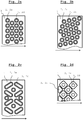
- FIG. 2a Fig. 2a, Fig. 2b, Fig. 2c and Fig. 2d drainage elements 1 according to the invention are shown from above, the openings 3 are provided with inserts 2.
- the drainage element 1 has at least one row of openings 3. However, it preferably has several rows of openings 3, wherein the openings 3 of the successive rows are arranged offset to one another, as in FIG Fig. 2a shown.
- Fig. 2a The rows run at an angle of 90 ° to the direction of the screen, which is indicated by the arrow.
- Fig. 2b The rows can also run obliquely to the direction of the screen.
- openings 3 and inserts 2 have circular cross sections.
- the inserts 2 can according to one of the embodiments of the Fig. 3a, Fig. 3b and Fig. 3c be executed.
- the insert 2 of the Fig. 3a has an over the entire circumference extending locking projection 2h, resulting in an annular locking surface 2c.
- the inserts 2 of the Fig. 3b and Fig. 3c Four locking projections 2c, which are distributed at regular intervals over the circumference of the insert 2.
- the inserts 2 of the Fig. 3a and Fig. 3b have a Einpresskegel 2e.
- the insert 2 of the Fig. 3c has a substantially constant annular cross-section from which protrude the locking projections 2c.
- the locking projections 2c have at their lower end to a radially tapered region, which takes over the function of the Einpresskegels 2e.
- a locking projection 2h extending over the entire circumference in this manner, that is to say with a press-in cone 2e spaced apart from the support surface 2b.
- the openings 3 can also be arranged distributed in other patterns over the drainage element 1, as in Fig. 2c shown.
- differently shaped openings 3 and inserts 2 can be used.
- the opening 3 may be designed as a slot, wherein the insert 2 has a longitudinal oval shape.
- the execution of a longitudinal oval insert 2 is in Fig. 3d shown.
- the inserts 2 can also have an arbitrarily shaped sliding surface 2a.
- the insert 2 at the left edge of the dewatering element 1 has a triangular shape and has no insertion opening 2d.
- Such inserts 2 without insert opening 2d are seen in the running direction of the wire, preferably along the front and / or rear edge of the dewatering element 1, since more wear occurs at the edges than in the area between the edges. Due to the wear, the edges gradually round off.
- the inserts 2 slightly spaced from the edge of the dewatering element 1 the extent of rounding is limited by the distance of the insert 2 from the edge.
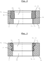
- the inserts 2 without insert opening 2d can according to the Fig. 6a and Fig. 6b be executed.
- Fig. 6a is the insert 2 at its lower end with a, a Einpresskegel 2e having, cylindrical fitting portion 2g provided.
- This under part of the insert 2 can be like the insert 2 of the Fig. 1 .
- Fig. 3a, Fig. 3b, Fig. 3c . 4 and FIG. 5 be formed, with no insertion opening 2d is present.
- the plate-shaped upper portion adjoining this lower portion can have any cross-sectional shape, for example triangular as in FIG FIG. 2d shown.
- This upper section can preferably be inserted into a correspondingly shaped insertion section 3e of the opening 3, or also analogously to Fig. 8 protrude beyond the top surface 1a.
- Fig. 6b a further variant of the insert 2 without insert opening 2d is shown.
- the plate-shaped section itself is the fitting section 2g, which is inserted into the correspondingly identically shaped fitting opening 3a.
- From the periphery of the plate-shaped portion are one or more locking projections 2c, which engage in corresponding recesses in the lateral surface of the opening 3.
- insert 2 of Fig. 6b to provide with one or more arbitrarily shaped instert openings 2d and to provide the dewatering element 1 with a passage opening 3d.
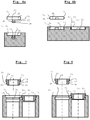
- Inserts 2 are shown in addition to the inserts 2 without insert opening 2d, which have a cylindrical insert opening 2d and an arbitrarily shaped sliding surface 2a.
- the sliding surfaces 2a of all inserts 2 are in Fig. 2d executed with rounded corners, this is in connection with the machining production of the openings 3, in which the radii are determined by the size of the milling cutter.
- the inserts 2 with approximately square sliding surfaces 2 a can advantageously according to Fig. 7 or Fig. 8 be shaped.
- the inserts have a lower portion, which like a in the Fig. 1 .
- Fig. 4 shown Insert 2 can be executed.
- a plate-shaped section which can have an arbitrary cross section and forms the sliding surface 2 a of the insert 2, still adjoins the fitting section 2 g at the top.
- the opening 3 preferably has an insertion opening 3e from the fitting opening 3a to the cover surface 1a, which serves to receive the plate-shaped section of the insert 2.
- the lower surface of the plate-shaped portion forms the support surface 2b, which rests on the support surface 1d of the dewatering element 1.
- the support surface 2b above the blocking surface 2c.
- the insert 2 may also be inserted so that the upper plate-shaped portion projects beyond the top surface 1a. In this case, the top surface 1a at the same time the support surface 1d.
- the insert of the Fig. 8 it would be conceivable not to make the upper section plate-shaped but as a spherical segment.
- Fig. 4 a preferred embodiment of the locking surface 1c and the locking surface 2c is shown.
- the blocking surface 2c of the latching element 2h is inclined starting from the fitting section 2g away from the sliding surface 2a and lies congruently in the inserted state on the latching surface 1c.
- the insert 2 With a suitable tool which moves from above through the opening 2d and is attached to the part of the support surface 2b protruding beyond the support surface 1d, the insert 2 can be drawn from the opening 3 from above.
- the pull-out resistance depends on the inclination of the blocking surface 2c.
- Fig. 5 1 shows an embodiment of the insert 2 and the opening 3, in which the insert 2 does not need to have a press-in cone 2e, since the opening 3 has a funnel-shaped area, which promotes the press-fitting of the insert 2.
Landscapes
- Sink And Installation For Waste Water (AREA)
- Paper (AREA)
- Processing Of Solid Wastes (AREA)
Description
- Die Erfindung betrifft ein Entwässerungselement aus Kunststoff, welches Inserts, insbesondere Keramikinserts aufweist.
- Ein Entwässerungselement wird in Papiermaschinen sowie Karton-, Zellstoff- und Tissuemaschinen zur Entwässerung der Fasersuspension verwendet. Das gegenständliche Insert bzw. Keramikinsert findet insbesondere bei Entwässerungselementen von Saugkästen (Vakuumsaugern, Unterdrucksaugern) Verwendung. Das Entwässerungselement bildet die obere Deckfläche (den Deckel, die Abdeckung) des Saugkastens und wird im Englischen als "Suction box cover" bezeichnet. Das Entwässerungselement weist zur Befestigung an seiner untern Seite in der Regel zwei oder mehr Nuten zur Aufnahme von T-Schienen des Saugkastens auf.
- Der Saugkasten ist ein Teil der Siebpartie der Papiermaschine. In der Siebpartie wird die Fasersuspension auf die obere Seite eines umlaufenden endlosen Siebs aus Kunststoff oder Metall aufgebracht. Dieses Sieb gleitet mit seiner Unterseite über das Entwässerungselement. Das Entwässerungselement weist Öffnungen auf, durch welche mittels Anlegen von Unterdruck der Fasersuspension durch das Sieb hindurch Flüssigkeit entzogen wird.
- Da das Sieb durch den Unterdruck gegen das Entwässerungselement gedrückt wird, muss das Entwässerungselement äußerst glatt und verschleißbeständig ausgeführt sein, um Verschleiß am Sieb und am Entwässerungselement selbst zu minimieren.
- Daher sind für Entwässerungselemente sehr harte Materialien am besten geeignet. Nach dem Stand der Technik ist es bekannt, Entwässerungselemente zur Gänze aus Keramik oder zur Gänze aus Kunststoff wie glasfaserverstärkter Kunststoff (GFK) zu fertigen, oder beispielsweise aus Stahl mit Keramikbeschichtung. Es ist auch bekannt Keramikleisten oder Keramiksegmente auf einem Träger, insbesondere auf länglichen T-Schienen aus Kunststoff oder Stahl, zu befestigen.
- Besonders vorteilhaft hat sich jedoch der Lochbelag für Entwässerungselemente erwiesen, bei welchem das Entwässerungselement selbst viele Öffnungen aufweist, da so die bestmögliche Entwässerung erreicht wird, da beim Lochbelag im Vergleich zu anderen Designs die offene Fläche, an der Vakuum anliegen kann, am höchsten ist und der Lochbelag ein gleichmäßigeres und schonenderes Entwässerungsprofil aufweist.
- Das Lochdesigne kann durch Öffnungen in einer zur Gänze aus Keramik oder zur Gänze aus Kunststoff bestehenden Oberfläche des Entwässerungselements vorgesehen sein.
- Die Keramik-Ausführung hat den Vorteil, dass aufgrund der hohen Härte und der äußerst glatten Oberfläche der Verschleiß minimal ist. Die Keramik-Ausführung hat den Nachteil, dass große Elemente aus Keramik schwierig zu produzieren und teuer sind, zudem muss bei einer Beschädigung des Elements das ganze Element ersetzt werden.
- Die Kunststoff-Ausführung hat den Vorteil, dass diese günstiger und in der Herstellung einfacher ist, mit dem Nachteil, dass sie eine geringere Härte und somit mehr Verschleiß aufweist als die Keramik-Ausführung.
- Daher wurden Entwässerungselemente entwickelt, welche Oberflächenbereiche aus unterschiedlichen Materialien, insbesondere Kunststoff und Keramik aufweisen, um deren Vorteile zu kombinieren.
- Die
US 3404066 A zeigt ein Entwässerungselement, das aus einer Platte aus Hartholz besteht und welches den Saugkasten zur Gänze abdeckt. Die Platte ist mit Bohrungen versehen, welche zum Durchtritt von Flüssigkeit in den Saugkasten dienen. Um den Verschleiß an den Lochkanten der Hartholzplatte zu minimieren, wird vorgeschlagen, hohlzylindrische Keramikinserts (bzw. allgemein Inserts mit einer hohen Härte, oder mit hartem Material beschichtete Inserts) in diese Bohrungen einzusetzen. Dazu weisen die Bohrungen zwei zylindrische Bereiche auf, wobei der zylindrische Bereich, welcher dem Sieb zugewandt liegt den gleichen Durchmesser hat wie der Hohlzylinder des Keramikinserts, und der untere zylindrische Bereich den gleichen Durchmesser hat, wie der Innendurchmesser des Keramikinserts. Das Keramikinsert wird mit einem Epoxid-Kleber in der Bohrung befestigt. Dieses Dokument offenbart die Merkmale des Oberbegriffs des vorliegenden Anspruchs 1. - Die
CA 2273674 A1 zeigt ein Entwässerungselement, welches aus einer Platte aus Kunststoff, bevorzugt Polyethylen besteht. Die Platte weist Öffnungen, insbesondere längliche Öffnungen auf. Diese Öffnungen sind an ihrem oberen Umfang mit einem endlosen Band aus härterem Material, insbesondere Keramik versehen, sodass dieses Material die obere Kante der Öffnung bildet, wobei diese Kante bevorzugt abgerundet ausgeführt ist. Das endlose Band selbst weist bevorzugt einen quadratischen Querschnitt auf, wobei sich bei einem kreisrunden Querschnitt der Öffnungen eine Keramikhülse wie bei der zuvor zitiertenUS 3404066 A ergibt. Das endlose Band kann auch einen runden, ovalen, oder trapezförmigen Querschnitt aufweisen. - Die
DE 1761174 A1 zeigt ein Entwässerungselement aus Kunststoff, welches unterschiedliche Keramikinserts aufweisen kann. Dabei kommen Inserts, welche eine Öffnung im Entwässerungselement umschließen und längliche Inserts, welche in das Material des Kunststoffs eingebettet sind zum Einsatz. Die Inserts, welche die Öffnungen umschließen, sind im Wesentlichen gemäß den vorgenannten Schriften ausgebildet. Die länglichen Inserts sind prismatisch mit einer trapezförmigen Grundfläche ausgeführt, wobei die kleinere der beiden parallelen Seitenflächen des trapezförmigen Prismas nach oben zeigt, sodass die Inserts formschlüssig vom Kunststoff umschlossen werden. Zur Herstellung des Entwässerungselements mit Öffnungen wird vorgeschlagen, die die Öffnungen umschließenden Inserts am Boden einer Guss- oder Sinterform zu platzieren und diese mit Kunststoff zu umschließen. Um die Inserts höhenverstellbar auszuführen, wird vorgeschlagen hohlzylindrische Inserts mit einem Gewinde zu versehen und von dieser Form abweichende Inserts verschiebbar in den Öffnungen zu halten. - Nachteilig am Stand der Technik ist, dass die Inserts entweder rein durch die Schwerkraft, bzw. die Sogwirkung, durch Kleben oder Verschrauben in den Öffnungen gehalten werden. Bei der Methode der Schwerkraft ist nachteilig, dass die Insert speziell beim Transport oder bei Demontage des Entwässerungselements aus den Öffnungen fallen können. Nachteilig am Kleben ist, dass die Inserts nicht oder nur mit hohem Aufwand wieder vollständig aus dem Entwässerungselement entfernt werden können. Nachteilig am verschrauben ist, dass die Inserts, bzw. das Entwässerungselement aufwendig zu bearbeiten sind, da zusätzliche Öffnungen, Aufnahmen und Befestigungen für die Schrauben vorhanden sein müssen. Da die Schrauben in der Regel nur von der Unterseite des Entwässerungselements zugänglich sind, ist eine Demontage des Inserts kompliziert.
- Beim Umgießen der Inserts mit Kunststoff in einer Form ist es zwar möglich die Inserts formschlüssig einzubetten, dies und das Herstellungsverfahren weisen jedoch nicht unwesentliche Nachteile auf. Durch die formschlüssige Einbettung durch Umgießen mit Kunststoff können die Inserts nicht getauscht werden, wenn diese beschädigt, oder verschlissen sind. Beim Versehen der Inserts mit einem Gewinde ist die Tauschbarkeit zwar gegeben, aber das Insert weist dabei eine komplexe Form auf und durch Vibrationen und Reibkräfte des Siebes kann es zu einer ungewollten Höhenverstellung kommen.
- Das Herstellungsverfahren, bestehend aus dem Platzieren der Inserts in einer Guss- oder Sinterform und das folgende Umschließen mit Kunststoff, hat den wesentlichen Nachteil, dass aufgrund der Fremdkörper in der Form ein gleichmäßiges Aushärten des Kunststoffs erschwert wird, was zu Spannungen im Kunststoffelement und/oder den Inserts führen kann, was sich negativ auf die Lebensdauer des Entwässerungselements bzw. der Inserts auswirkt. Zudem sind aufwendige Gussformen nötig, da Halteelemente zum Fixieren der Inserts in der Gussform benötigt werden.
- Die der Erfindung zu Grunde liegende Aufgabe besteht darin, eine formschlüssige Verbindung der Inserts im Kunststoff des Entwässerungselements zu erreichen, unter Vermeidung der oben genannten Nachteile.
- Für das Lösen der Aufgabe wird vorgeschlagen, die Inserts mit zumindest einem Rastelement, welches die Wirkung eines Widerhakens oder ähnlich einem Widerhaken hat, zu versehen, wobei das Rastelement bei Einstecken des Inserts mit einer Rastfläche in der Öffnung des Entwässerungselements in Eingriff kommt.
- Das erfindungsgemäße Verfahren zur Herstellung eines spannungsfreien Entwässerungselements mit formschlüssig befestigten Keramikinserts besteht darin, dass in einem ersten Schritt eine Platte aus Kunststoff, bevorzugt ultrahochmolekularem Polyethylen, gesintert wird.
- Diese Platte wird in Folge durch einen spanenden Bearbeitungsprozess, insbesondere Fräsen und/oder Bohren, mit Öffnungen versehen. Die Öffnungen weisen an einem von der Oberfläche der Platte entfernt liegenden Bereich einen Teilabschnitt mit größerem Querschnitt, bzw. einem größerem Durchmesser auf. Die nach bekannten Verfahren (z.B. Sintern mit eventuell nachfolgendem Schleifen) hergestellten Keramikinserts weisen in einem von beiden Deckflächen des Inserts beabstandet liegenden Bereich eine vergrößerten Querschnitt bzw. Durchmesser auf. Der vergrößerte Querschnitt bzw. Durchmesser des Inserts ist etwas größer als der Querschnitt bzw. Durchmesser des Teilbereichs der Öffnung, welcher an den Teilabschnitt der Öffnung mit größerem Querschnitt bzw. Durchmesser in Richtung der Oberfläche der Platte anschließt.
- Je ein Insert wird in je eine Öffnung des Entwässerungselements geschoben bzw. eingepresst, bis der vergrößerte Bereich des Inserts mit dem vergrößerten Bereich der Öffnung in Eingriff kommt. Das Insert ist in jenem Teilbereich, welcher sich in der Öffnung befindet, an seiner Mantelfläche, bzw. seinen Mantelflächen allseitig vom Kunststoff des Entwässerungselements umschlossen.
- Vorteilhaft an der gegenständlichen Erfindung ist, dass
- das Entwässerungselement aus einer spannungsfrei gefertigten Kunststoffplatte besteht,
- die Inserts formschlüssig in die Öffnungen des Entwässerungselements einsteckbar sind,
- die Inserts gegen Herausfallen und vertikales Verschieben gesichert sind
- und dennoch ein rasches Auswechseln einzelner Inserts möglich ist.
- Bevorzugt weist das Insert an jener Oberfläche mit der es mit dem Sieb in Kontakt kommt eine Keramikbeschichtung oder einen Keramikeinsatz auf, wobei das restliche Insert beispielsweise aus Stahl besteht.
- Besonders bevorzugt besteht das Insert zur Gänze aus technischer Keramik.
- Bevorzugt erstrecken sich die Öffnungen durch die gesamte Dicke des Entwässerungselements.
- Bevorzugt erstrecken sich die Öffnungen in einem Winkel von 90° zur Oberfläche durch das Entwässerungselement.
- Bevorzugt weist das Insert selbst eine Öffnung auf, welche sich über die gesamte Länge des Inserts erstreckt.
- Bevorzugt ist die Länge des Inserts geringer als die Dicke des Entwässerungselements.
- Bevorzug weisen die Öffnungen und die Inserts nur kreisförmige Querschnitte auf.
- Bevorzugt ist das Entwässerungselement nach dem erfindungsgemäßen Verfahren hergestellt.
- Ein erfindungsgemäßes Inserts ist jedoch auch bei einem anders hergestellten Entwässerungselement erfindungsgemäß einsetzbar, solange dieses zumindest eine erfindungsgemäße Öffnung aufweist.
- Das Entwässerungselement besteht bevorzugt aus einem verschleißfesten Kunststoff wie beispielsweise einem glasfaserverstärkter Kunststoff, oder Polyethylen.
- Die Erfindung wird an Hand von Zeichnungen veranschaulicht:
- Fig. 1:
- Zeigt ein besonders bevorzugtes erfindungsgemäßes Entwässerungselement in seitlicher Schnittansicht mit einem eingesetzt und einem noch einzusetzendem Insert.
- Fig. 2:
- Die
Fig. 2a, 2b, 2c und 2d zeigen beispielhafte erfindungsgemäße Entwässerungselemente von oben. - Fig. 3:
- Die
Fig. 3a, 3b, 3c und 3d zeigen je ein erfindungsgemäßes Insert in seitlicher Schnittansicht und von oben. - Fig. 4:
- Zeigt ein Entwässerungselement mit einem einfach entfernbarem Insert in seitlicher Schnittansicht.
- Fig. 5:
- Zeigt ein Entwässerungselement mit Insert in seitlicher Schnittansicht, wobei das Entwässerungselement einen trichterförmigen Einpressbereich aufweist.
- Fig. 6:
- Die
Fig. 6a und 6b zeigen Entwässerungselemente in seitlicher Teilschnittansicht mit Inserts, welche keine Öffnung aufweisen. - Fig. 7:
- Zeigt ein Entwässerungselement mit einem Insert, welches eine beliebig geformte Deckfläche aufweist, in seitlicher Schnittansicht.
- Fig. 8:
- Zeigt ein Entwässerungselement mit einem Insert, dessen Gleitfläche über die Deckfläche des Entwässerungselements vorragt, in seitlicher Schnittansicht.
- In
Fig. 1 ist ein erfindungsgemäßes Entwässerungselement 1 mit zwei Inserts 2 gezeigt, wobei das Entwässerungselement 1 zwei Öffnungen 3 aufweist. Die obere Fläche des Entwässerungselements 1, über welche das Sieb gleitet, wird in Folge als Deckfläche 1a bezeichnet, die untere Fläche, welche dem Inneren des Saugkastens zugewandt liegt, als Grundfläche 1b. - In diesem Beispiel weist die Öffnung 3 in jedem Bereich einen kreisförmigen Querschnitt auf. Zudem sind zwei Inserts 2 gezeigt, wobei eines davon in eine Öffnung 3 eingesetzt ist.
- Die Öffnung 3 weist zumindest zwei Bereiche mit unterschiedlichem Durchmesser auf. Im gegenständlichen Beispiel weist die Öffnung 3 vier Bereiche mit unterschiedlichem Durchmesser auf.
- Anschließend an die Deckfläche 1a weist die Öffnung 3 einen zylindrischen Bereich auf, welcher als Passung für das Insert 2 dient, dieser Bereich wird in Folge als Passöffnung 3a bezeichnet. Die Passung zwischen Insert 2 und Abdeckelement 1 ist so gewählt, dass ein spaltloser Übergang von der Deckfläche 1a zur Gleitfläche 2a des Inserts 2 erreicht wird.
- Im nächsten Abschnitt der Öffnung 3, anschließend an die Passöffnung 3a, folgt ein Bereich mit größerem Durchmesser als jenem der Passöffnung 3a. Dieser Bereich dient zur Aufnahme des Rastelements des Inserts 2 und wird in Folge als Aufnahmeöffnung 3b bezeichnet. Durch die sprunghafte Vergrößerung des Durchmessers von der Passöffnung 3a auf die Aufnahmeöffnung 3b ergibt sich im Abdeckelement 1 eine ringförmige Fläche, welche parallel zur Deckfläche 1a ausgerichtet ist. Diese ringförmige Fläche wird in Folge als Rastfläche 1c bezeichnet. Die Aufnahmeöffnung 3b bildet eine ringsum verlaufende Ausnehmung in der Mantelfläche der Öffnung 3. Diese Ausnehmung ist von der Deckfläche 1a beabstandet.
- Die Aufnahmeöffnung 3b geht an ihrem unteren Ende in einen kegelstupfförmigen Bereich 3c der Öffnung 3 über. Dieser kegelstumpfförmige Bereich 3c ist fertigungstechnisch bedingt und ergibt sich bei Verwendung eines kegelstumpfförmigen Fräsers. Wird ein zylindrischer Fräser verwendet, kann dieser Bereich der Öffnung 3 auch zylindrisch geformt sein.
- Der kegelstumpfförmige Bereich 3c weist an seinem unteren Ende eine sprunghafte Verkleinerung des Durchmessers auf, wodurch im Entwässerungselement eine ringförmige Auflagefläche 1d gebildet wird, auf welcher das Insert 2 mit seiner unteren Stützfläche 2b aufliegt. Das Insert 2 ist mit seinen Flächen 2c, 2b zwischen den Flächen 1c, 1d des Entwässerungselements so eingepasst, dass keine vertikale Bewegung des Inserts 2 möglich ist.
- Am unteren Ende des kegelstumpfförmigen Bereichs 3c schließt die Durchgangsöffnung 3d an, welche sich bis zur Grundfläche 1b des Entwässerungselements 1 erstreckt.
- Das Insert 2 weist in etwa eine hohlzylindrische Form auf, mit einem im Wesentlichen konstanten Innendurchmesser der Insertöffnung 2d. Das Insert 2 weist bevorzugt an der oberen Kante der Insertöffnung 2d eine Rundung oder eine Phase auf. Die Deckfläche des Hohlzylinders des Inserts 2, über welche das Sieb gleitet, wird in Folge als Gleitfläche 2a bezeichnet, die Grundfläche des Hohlzylinders, welche auf der Auflagefläche 1d aufliegt als Stützfläche 2b. Die Stützfläche 2b weist einen geringeren Außendurchmesser auf als die Öffnung 3a.
- An die Stützfläche 2b schließt eine Einpressfase, bzw. der Einpresskegel 2e an, bei welchem der Außendurchmesser des Inserts 2 kontinuierlich größer wird, bis dessen Durchmesser den Durchmesser der Passöffnung 3a etwas übersteigt. An den Einpresskegel 2e schließt ein kurzer Bereich 2f mit konstantem Durchmesser an, welcher schließlich sprunghaft zum Passabschnitt 2g übergeht und so einen ringförmige Sperrfläche 2c bildet, welche parallel zur Gleitfläche 2a und parallel zur Stützfläche 2b ausgerichtet ist.
- Beim Einsetzen des Inserts 2 lässt sich dessen Einpresskegel 2e zunächst leicht in die Öffnung 3a einführen, bis dessen Durchmesser den der Öffnung 3a übersteigt. Die benötigte Kraft zum Einpressen nimmt dann kontinuierlich zu, bis der kurze Bereich 2f die Passöffnung 3a erreicht und entlang dieser mit gleichbleibender Kraft nach unten geschoben wird. Sobald der kurze Bereich 2f die Passöffnung 3a passiert hat, gelangt der kurze Bereich 2f in die Aufnahmeöffnung 3b, die den gleichen oder etwas größeren Durchmesser wie der kurze Bereich 2f aufweist. In dieser Position ist das Insert vertikal durch die Flächen 2c, 2b und horizontal durch den Passabschnitt 2g in die Öffnung 3 eingepasst, wodurch eine vertikale oder horizontale Bewegung des Inserts 2 verhindert wird. Die Sperrfläche 2c und der über den Passabschnitt 2g vorstehende Teil des kurzen Bereichs 2f und des Einpresskegels 2e formen den Sperrvorsprung 2h.
- Der Sperrvorsprung 2h kann sich, wie zuvor beschrieben, über den gesamten Umfang des Inserts 2 erstrecken, oder nur über einen oder mehrere Teilbereiche des Umfangs des Inserts 2. Gleiches gilt für die Aufnahmeöffnung 3b.
- Der Innendurchmesser des Inserts 2 beträgt beispielsweise 14 mm, der Außendurchmesser ca. 20 mm. Die Dicke D des Entwässerungselements 1 beträgt beispielsweise 40 mm. Die Länge L des Inserts beträgt beispielsweise ca. 7 mm. Die Breite der ringförmigen Sperrfläche 2c beträgt zirka 0,5 mm. Die Breite der ringförmigen Sperrfläche 2c ist dabei von der Elastizität bzw. der Härte des Kunststoffs des Entwässerungselements 1 abhängig. Je härter der Kunststoff ist desto geringer kann die Breite der Sperrfläche 2c dimensioniert werden.
- Das Entwässerungselement 1 kann im Langzeitsinterpressverfahren als bis zu 12 m langer Belag oder Leiste ohne Schweißnaht, mit spannungsfreier Struktur hergestellt werden. Die Breite eines Entwässerungselements 1 mit sieben parallelen Reihen von Öffnungen 3 beträgt beispielsweise 220 mm. Die Breite des Entwässerungselements 1 ist die Erstreckung des Entwässerungselements 1 in Laufrichtung des Siebes. Die Breite eines Entwässerungselements 1 kann auch größer (oder kleiner) gewählt sein, beispielsweise beträgt die Breite über 500 mm, wobei die Unterstützung durch den Unterbau in einem Raster von ca. 250 mm auszuführen ist. Diese Unterstützung besteht in einer Befestigung des Entwässerungselements 1, die so auszulegen ist, dass sich das Entwässerungselement 1 ungehindert ausdehnen kann (T-Schienen, Winkelleisten, Schwalbenschwanzführungen, Schrauben in Langlöcher).
- Erfindungsgemäß ist es auch denkbar, dass das Entwässerungselement 1 nicht aus einer durchgehenden Platte gefertigt ist, sondern aus mehreren in erfindungsgemäßer Weise gefertigten Platten bzw. Entwässerungselementen 1 besteht, welche miteinander verschweißt werden, oder aneinander folgend in Längs- oder Querrichtung der Laufrichtung des Siebes aneinander folgend montiert werden. Beispielsweise deckt dann ein erfindungsgemäßes Entwässerungselement 1 nur einen Teilbereich der Breite des Siebes ab. Ein erfindungsgemäße Entwässerungselement 1 selbst kann eine beliebige Form aufweisen, wobei die Form einer rechteckigen Platte in den meisten Fällen vorteilhaft sein wird.
- Der Widerstand, welchen das Insert 2 gegen das Herausziehen aus dem Entwässerungselement 1 aufbringt, kann über die Breite der ringförmigen Sperrfläche 2c und/ oder deren Neigung zur Deckfläche 1a, bzw. der Gleitfläche 2a eingestellt werden. Wobei eine Änderung der Neigung der Sperrfläche 2c keinen Einfluss auf die nötige Einpresskraft zum Einsetzen des Inserts 2 hat.
- Ist die Sperrfläche 2c ausgehend von ihrer gemeinsamen Kante mit dem Passzylinder 2g zur Deckfläche 1a hin geneigt, so bildet der Sperrvorsprung 2h einen Widerhaken. Dieser verhakt sich beim Versuch das Insert 2 herauszuziehen im Kunststoff des Entwässerungselements 1. Ein zerstörungsfreies Entfernen des Inserts 2 ist dann nicht möglich.
- Ist die Sperrfläche 2c ausgehend von ihrer gemeinsamen Kante mit dem Passzylinder 2g von der Deckfläche 1a weg geneigt, so bildet die Sperrfläche 2c ein kegelstumpfförmigen Sperrvorsprung 2h. Weist dieser Kegelstumpf beispielsweise die gleiche Neigung wie der Einpresskegel 2e auf, so ist für das Herausziehen die gleiche Kraft notwendig wie für das Einpressen des Inserts 2. Ein solches Insert 2 kann bei Bedarf jederzeit zerstörungsfrei entfernt und durch ein neues Insert 2 ersetzt werden, oder bei einem anderen Entwässerungselement 1 eingesetzt werden.
- Durch die Erfindung ist es auch möglich bereits in Verwendung befindliche Voll-Kunststoff-Entwässerungselemente nachträglich mit Inserts 2 zu versehen, durch Bohren oder Fräsen der Passöffnung 3a und Fräsen der Aufnahmeöffnungen 3b.
- In
Fig. 2a, Fig. 2b, Fig. 2c und Fig. 2d sind erfindungsgemäße Entwässerungselemente 1 von oben gezeigt, deren Öffnungen 3 mit Inserts 2 versehen sind. Das Entwässerungselement 1 weist dabei zumindest eine Reihe von Öffnungen 3 auf. Bevorzugt weist es jedoch mehrere Reihen von Öffnungen 3 auf, wobei die Öffnungen 3 der aufeinanderfolgenden Reihen versetzt zueinander angeordnet sind wie inFig. 2a gezeigt. InFig. 2a verlaufen die Reihen in einem Winkel von 90° zur Laufrichtung des Siebes, welche mit dem Pfeil angedeutet ist. Wie inFig. 2b gezeigt können die Reihen auch schräg zur Laufrichtung des Siebes verlaufen. Die inFig. 2a und 2b gezeigten Öffnungen 3 und Inserts 2 weisen kreisförmige Querschnitte auf. Die Inserts 2 können gemäß einem der Ausführungsbeispiele derFig. 3a, Fig. 3b und Fig. 3c ausgeführt sein. Das Insert 2 derFig. 3a weist einen über den gesamten Umfang verlaufenden Sperrvorsprung 2h auf, wodurch sich eine ringförmige Sperrfläche 2c ergibt. Die Inserts 2 derFig. 3b und Fig. 3c , weisen vier Sperrvorsprünge 2c auf, die in regelmäßigen Abständen über den Umfang des Inserts 2 verteilt sind. Die Inserts 2 derFig. 3a und Fig. 3b weisen einen Einpresskegel 2e auf. - Das Insert 2 der
Fig. 3c weist einen im Wesentlichen konstanten ringförmigen Querschnitt auf, von welchem die Sperrvorsprünge 2c abstehen. Die Sperrvorsprünge 2c weisen an ihrem unteren Ende einen sich radial verjüngenden Bereich auf, welcher die Funktion des Einpresskegels 2e übernimmt. Natürlich wäre es auch denkbar einen über den gesamten Umfang verlaufenden Sperrvorsprung 2h in dieser Weise auszuführen, also mit einem zur Stützfläche 2b beabstandeten Einpresskegel 2e. - Die Öffnungen 3 können auch in anderen Mustern über das Entwässerungselement 1 verteilt angeordnet sein, wie in
Fig. 2c gezeigt. Dabei können unterschiedlich geformte Öffnungen 3 und Inserts 2 zum Einsatz kommen. Wie inFig. 2c gezeigt, kann die Öffnung 3 als Langloch ausgeführt sein, wobei das Insert 2 eine längsovale Form aufweist. Die Ausführung eines längsovalen Inserts 2 ist inFig. 3d gezeigt. Besonders bei von der Kreisform, bzw. Ringform abweichenden Querschnitten des Inserts 2 ist es vorteilhaft, mehrere Sperrvorsprünge 2h über den Umfang des Inserts 2 verteilt anzuordnen. In diesem Fall ist es ausreichend, den Querschnitt der Öffnung 3 nur in jenen Bereichen größer auszuführen, in welchen die Sperrvorsprünge 2h im eingesetzten Zustand zur Lage kommen. - Wie in
Fig. 2d gezeigt können die Inserts 2 auch eine beliebig geformte Gleitfläche 2a aufweisen. Das Insert 2 am linken Rand des Entwässerungselements 1 weist eine dreieckige Form auf und besitzt keine Insertöffnung 2d. Solche Inserts 2 ohne Insertöffnung 2d sind in Laufrichtung des Siebes gesehen, bevorzugt entlang der vorderen und/oder hinteren Kante des Entwässerungselements 1 vorgesehen, da an den Kanten größerer Verschleiß auftritt als im Bereich zwischen den Kanten. Durch den Verschleiß runden die Kanten allmählich ab. Dadurch, dass die Inserts 2 etwas beabstandet zur Kante des Entwässerungselements 1 angebracht sind, wird das Ausmaß der Rundung durch den Abstand des Inserts 2 von der Kante begrenzt. - Die Inserts 2 ohne Insertöffnung 2d können gemäß den
Fig. 6a und Fig. 6b ausgeführt sein. InFig. 6a ist das Insert 2 an seinem unteren Ende mit einem, einen Einpresskegel 2e aufweisenden, zylinderförmigen Passabschnitt 2g versehen. Dieser unter Teil des Inserts 2 kann wie das Insert 2 derFig. 1 ,Fig. 3a, Fig. 3b, Fig. 3c ,Fig. 4 und Fig. 5 ausgebildet sein, wobei keine Insertöffnung 2d vorhanden ist. Der an diesen untern Abschnitt anschließende, plattenförmige obere Abschnitt kann eine beliebige Querschnittsform aufweisen, beispielsweise dreieckig wie inFig. 2d gezeigt. Dieser obere Abschnitt kann bevorzugt in einen entsprechend gleich geformten Einsetzabschnitt 3e der Öffnung 3 eingesetzt werden, oder auch analog zurFig. 8 über die Deckfläche 1a vorstehen. - In
Fig. 6b ist eine weitere Variante des Inserts 2 ohne Insertöffnung 2d gezeigt. Dabei ist der plattenförmige Abschnitt selbst der Passabschnitt 2g, welcher in die entsprechend gleich geformte Passöffnung 3a eingesetzt wird. Vom Umfang des plattenförmigen Abschnitts stehen ein oder mehrere Sperrvorsprünge 2c ab, welche in entsprechenden Ausnehmungen in der Mantelfläche der Öffnung 3 einrasten. Als Abwandlung ist es denkbar das Insert 2 derFig. 6b mit einer oder mehreren beliebig geformten Instertöffnungen 2d zu versehen und das Entwässerungselement 1 mit einer Durchgangsöffnung 3d zu versehen. - In
Fig. 2d sind neben den Inserts 2 ohne Insertöffnung 2d auch Inserts 2 gezeigt, die eine zylinderförmige Insertöffnung 2d aufweisen und eine beliebig geformte Gleitfläche 2a. - Die Gleitflächen 2a aller Inserts 2 sind in
Fig. 2d mit abgerundeten Ecken ausgeführt, dies ergibt sich in Zusammenhang mit der spanenden Erzeugung der Öffnungen 3, bei welcher die Radien durch die Größe des Fräsers vorgegeben sind. Die Inserts 2 mit annähernd quadratischen Gleitflächen 2a können vorteilhaft gemäßFig. 7 oder Fig. 8 geformt sein. Die Inserts weisen dabei einen unteren Abschnitt auf, welcher wie ein in denFig. 1 ,Fig. 3a, Fig. 3b, Fig. 3c ,Fig. 4 gezeigtes Insert 2 ausgeführt sein kann. An den Passabschnitt 2g schließt jedoch noch oben hin ein plattenförmiger Abschnitt an, welcher einen beliebigen Querschnitt aufweisen kann und die Gleitfläche 2a des Inserts 2 bildet. - Wie in
Fig. 7 gezeigt, weist die Öffnung 3 bevorzugt von der Passöffnung 3a bis zur Deckfläche 1a eine Einsatzöffnung 3e auf, welche zur Aufnahme des plattenförmigen Abschnitts des Inserts 2 dient. Die untere Fläche des plattenförmigen Abschnitts bildet die Stützfläche 2b, welche auf der Auflagefläche 1d des Entwässerungselements 1 aufliegt. Im Gegensatz zu den Inserts 2 derFig. 1 befindet sich die Stützfläche 2b oberhalb der Sperrfläche 2c. - Wie in
Fig. 8 gezeigt, kann das Insert 2 auch so eingesetzt werden, dass der obere plattenförmige Abschnitt über die Deckfläche 1a vorsteht. In diesem Fall ist die Deckfläche 1a zugleich die Auflagefläche 1d. In Abwandlung des Inserts derFig. 8 wäre es denkbar, den oberen Abschnitt nicht plattenförmig sondern als Kugelsegment auszuführen. - In
Fig. 4 ist eine bevorzugt Ausgestaltung der Rastfläche 1c und der Sperrfläche 2c gezeigt. Die Sperrfläche 2c des Rastelements 2h ist dabei ausgehend vom Passabschnitt 2g von der Gleitfläche 2a weg geneigt und liegt im eingesetzten Zustand deckungsgleich an der Rastfläche 1c an. Mit einem geeignetem Werkzeug, welches von oben durch die Öffnung 2d bewegt und an dem über die Auflagefläche 1d vorstehenden Teil der Stützfläche 2b angesetzt wird, kann das Insert 2 von oben aus der Öffnung 3 gezogen werden. Der Widerstand gegen das Herausziehen hängt von der Neigung der Sperrfläche 2c ab. - In
Fig. 5 ist eine Ausgestaltung des Inserts 2 und der Öffnung 3 gezeigt, bei welcher das Insert 2 keinen Einpresskegel 2e aufzuweisen braucht, da die Öffnung 3 einen trichterförmigen Bereich aufweist, welcher das Einpressen des Inserts 2 begünstigt. - In der Figurenbeschreibung wurden vorteilhaft Merkmale der Erfindung beschrieben, diese können im Rahmen des fachmännischen Handelns beliebig kombiniert werden und es können auch unterschiedlich ausgestaltete Inserts 2 an einem Entwässerungselement 1 vorhanden sein.
Claims (15)
- Entwässerungselement (1) aus Kunststoff, welches zumindest eine Öffnung (3) aufweist, in welche ein Insert (2) eingesetzt ist, wobei das Insert (2) gegenüber dem Entwässerungselement (1) eine härtere Oberfläche aufweist, dadurch gekennzeichnet, dass
das Insert (2) an seinem Außenumfang zumindest einen Sperrvorsprung (2h) mit einer Sperrfläche (2c) aufweist,
das Entwässerungselement (1) in der Öffnung (3) zumindest eine Rastfläche (1c) aufweist, welche durch eine Ausnehmung in der Mantelfläche der Öffnung (3) gebildet ist,
das Insert (2) in die Öffnung (3) einpressbar ist,
wobei der Sperrvorsprung (2h) in die Ausnehmung in der Mantelfläche der Öffnung (3) ragt und die Sperrfläche (2c) des Sperrvorsprungs (2h) aus jener Richtung in Eingriff mit der Rastfläche (1c) ist, welche entgegengesetzt der Richtung liegt, aus welcher das Insert (2) in die Öffnung (3) eingepresst wurde. - Entwässerungselement (1) nach Anspruch 1, dadurch gekennzeichnet, dass das Entwässerungselement (1) eine Auflagefläche (1d) aufweist und eine Stützfläche (2b) des Inserts (2) in jener Richtung in Eingriff mit der Auflagefläche (1d) ist, in der das Insert (2) in die Öffnung (3) eingepresst wurde.
- Entwässerungselement (1) nach einem der Ansprüche 1 und 2, dadurch gekennzeichnet, dass die Öffnung (3) eine Passöffnung (3a) aufweist, in welche das Insert (2) im eingesetzten Zustand mit dem Passabschnitt (2g) eingepasst und gegen horizontale Bewegung gesichert ist.
- Entwässerungselement (1) nach Anspruch 3, dadurch gekennzeichnet, dass der Passabschnitt (2g) des Inserts (2) eine zylindrische Form aufweist.
- Entwässerungselement (1) nach einem der Ansprüche 3 bis 4, dadurch gekennzeichnet, dass das Insert (2) anschließend an den Passabschnitt (2g) in Richtung der Gleitfläche (2a) einen Bereich aufweist, welcher gegenüber dem Passabschnitt (2g) einen größeren, beliebig geformten Querschnitt aufweist.
- Entwässerungselement (1) nach einem der Ansprüche 1 bis 5, dadurch gekennzeichnet, dass die Gleitfläche (2a) des Inserts (2) und die Deckfläche (1a) des Entwässerungselements (1) in einer Ebene liegen.
- Entwässerungselement (1) nach einem der Ansprüche 1 bis 6, dadurch gekennzeichnet, dass die Öffnung (3) von der Deckfläche (1a) des Entwässerungselements (1) bis zur Grundfläche (1b) des Entwässerungselements (1) verläuft und dass das Insert (2) eine Insertöffnung (2d) aufweist, welche sich ausgehend von der Gleitfläche (2a) über die gesamte Länge L des Inserts (2) erstreckt.
- Entwässerungselement (1) nach einem der Ansprüche 1 bis 7, dadurch gekennzeichnet, dass die Öffnung (3) des Entwässerungselements (1) und das Insert (2) nur kreis- oder ringförmige Querschnitte aufweisen.
- Entwässerungselement (1) nach einem der Ansprüche 1 bis 8, dadurch gekennzeichnet, dass der zumindest eine Sperrvorsprung (2h) an seiner von der Gleitfläche (2a) und der Sperrfläche (2c) abgewandt liegenden Seite einen konischen bzw. einen sich verjüngenden Abschnitt aufweist.
- Entwässerungselement (1) nach einem der Ansprüche 1 bis 9, dadurch gekennzeichnet, dass die Sperrfläche (2c) des Inserts (2) zur Gleitfläche (2a) hin oder von dieser weg geneigt ausgerichtet ist.
- Entwässerungselement (1) nach einem der Ansprüche 1 bis 10, dadurch gekennzeichnet, dass der Sperrvorsprung (2h) über den gesamten Umfang des Inserts (2) verläuft und sich die Ausnehmung in der Mantelfläche der Öffnung (3) über den gesamten Umfang der Öffnung (3) erstreckt.
- Entwässerungselement (1) nach einem der Ansprüche 1 bis 11, dadurch gekennzeichnet, dass das Insert (2) an seiner von der Gleitfläche (2a) abgewandten Seite einen kegelstumpfförmigen Bereich, der als Einpresskegel (2e) dient, aufweist.
- Entwässerungselement (1) nach einem der Ansprüche 1 bis 12, dadurch gekennzeichnet, dass die Gleitfläche (2a) des Inserts durch Keramik gebildet ist, oder das Insert (2) zur Gänze aus Keramik besteht.
- Entwässerungselement (1) nach einem der Ansprüche 1 bis 13, dadurch gekennzeichnet, dass es zur Gänze aus verschleißfestem Kunststoff, insbesondere ultrahochmolekularem Polyethylen besteht.
- Verfahren zur Herstellung eines Entwässerungselements (1) gemäß einem der Ansprüche 1 bis 14, dadurch gekennzeichnet, dass
das Entwässerungselement (1) in Form einer durchgehenden Platte aus Kunststoff hergestellt, insbesondere aus ultrahochmolekularem Polyethylen gesintert wird,
das Entwässerungselement (1) danach mit spanenden Bearbeitungsverfahren mit Öffnungen (3) versehen wird,
Inserts (2) mit einer härteren, verschleißfesteren Oberfläche, insbesondere Keramikinserts, in die Öffnungen (3) eingepresst werden.
Applications Claiming Priority (2)
| Application Number | Priority Date | Filing Date | Title |
|---|---|---|---|
| ATA50282/2014A AT515202B1 (de) | 2014-04-15 | 2014-04-15 | Entwässerungselement mit Insert |
| PCT/AT2015/050094 WO2015157787A1 (de) | 2014-04-15 | 2015-04-14 | Entwässerungselement mit insert |
Publications (2)
| Publication Number | Publication Date |
|---|---|
| EP3132091A1 EP3132091A1 (de) | 2017-02-22 |
| EP3132091B1 true EP3132091B1 (de) | 2017-11-15 |
Family
ID=53547641
Family Applications (1)
| Application Number | Title | Priority Date | Filing Date |
|---|---|---|---|
| EP15744848.1A Active EP3132091B1 (de) | 2014-04-15 | 2015-04-14 | Entwässerungselement mit insert |
Country Status (5)
| Country | Link |
|---|---|
| US (1) | US9834888B2 (de) |
| EP (1) | EP3132091B1 (de) |
| CN (1) | CN106460333A (de) |
| AT (1) | AT515202B1 (de) |
| WO (1) | WO2015157787A1 (de) |
Families Citing this family (2)
| Publication number | Priority date | Publication date | Assignee | Title |
|---|---|---|---|---|
| AU2017100428A4 (en) * | 2016-05-04 | 2017-05-18 | Warn Industries, Inc. | A composite fairlead with a wear plate |
| CN218539115U (zh) * | 2022-09-20 | 2023-02-28 | 杭州天铭科技股份有限公司 | 导绳器保护套及导绳器 |
Family Cites Families (8)
| Publication number | Priority date | Publication date | Assignee | Title |
|---|---|---|---|---|
| US3365359A (en) * | 1964-12-10 | 1968-01-23 | Proulx Jean | Suction box covers for paper making machines |
| US3404066A (en) | 1965-02-17 | 1968-10-01 | Union Carbide Corp | Suction box cover |
| SE349341B (de) | 1967-04-17 | 1972-09-25 | Leder & Riemen Patent | |
| CH537490A (de) * | 1972-02-03 | 1973-05-31 | Huyck Corp | Zum Stützen des Langsiebes einer Papiermaschine dienende Wasserabziehleiste |
| DE8714492U1 (de) * | 1987-07-31 | 1987-12-10 | KONUS, kemijska in usnjarska predelovalna industrija n.sol.o. TOZD KOTERM n.sub.o., Slovenske Konjice | Perforierte Platte für die nasse Partie einer Papier- bzw. Zellulosemaschine |
| CA2273674A1 (en) | 1998-06-09 | 1999-12-09 | Weavexx Corporation | Reduced wear suction box cover for dewatering device |
| US6254729B1 (en) * | 1999-03-22 | 2001-07-03 | Voith Sulzer Paper Technology North America, Inc. | Pulper with extraction plate assembly having removable inserts and method of manufacturing same |
| DE202010002332U1 (de) * | 2010-02-12 | 2010-09-30 | Wedi Gmbh | Unterbauelement zur Unterlegung eines Dusch-Bodenelementes |
-
2014
- 2014-04-15 AT ATA50282/2014A patent/AT515202B1/de not_active IP Right Cessation
-
2015
- 2015-04-14 EP EP15744848.1A patent/EP3132091B1/de active Active
- 2015-04-14 US US15/303,215 patent/US9834888B2/en active Active
- 2015-04-14 WO PCT/AT2015/050094 patent/WO2015157787A1/de not_active Ceased
- 2015-04-14 CN CN201580019488.5A patent/CN106460333A/zh active Pending
Non-Patent Citations (1)
| Title |
|---|
| None * |
Also Published As
| Publication number | Publication date |
|---|---|
| WO2015157787A1 (de) | 2015-10-22 |
| US9834888B2 (en) | 2017-12-05 |
| EP3132091A1 (de) | 2017-02-22 |
| AT515202B1 (de) | 2015-07-15 |
| AT515202A4 (de) | 2015-07-15 |
| CN106460333A (zh) | 2017-02-22 |
| US20170037571A1 (en) | 2017-02-09 |
Similar Documents
| Publication | Publication Date | Title |
|---|---|---|
| EP0904751B1 (de) | Rohrförmiger Stützkörper zum Überbrücken zweier Wirbel | |
| EP2922484B1 (de) | Chirurgische knochenschraube sowie implantationssystem | |
| EP2168513B1 (de) | Osteosyntheseplatte | |
| DE102013203938A1 (de) | Generatives Schichtaufbauverfahren zur Herstellung eines dreidimensionalen Objekts und dreidimensionales Objekt | |
| DE102007018025A1 (de) | Windenergieanlagenturm | |
| EP3046449A1 (de) | Perforationsvorrichtung für extraktionsgeräte zum herstellen von brühprodukten | |
| DE20201877U1 (de) | Kunststein für Pflasterzwecke | |
| WO1997036559A1 (de) | Prothesenteil | |
| DE102014203936A1 (de) | Verfahren zum Herstellen eines Rotorblatts einer Windenergieanlage, Rotorblatt und Windenergieanlage | |
| DE102016002435A1 (de) | Formrahmen mit verlagerbarer Formwand, Verwendung des Formrahmens sowie ein Formwandsystem mit verlagerbarer Formwand | |
| EP3132091B1 (de) | Entwässerungselement mit insert | |
| DE19532898A1 (de) | Künstliche Hüftgelenkpfanne | |
| DE19610843A1 (de) | Gekrümmtes Formteil, insbesondere für Möbel | |
| DE202007015255U1 (de) | Saugheber | |
| DE102015108230A1 (de) | Klingenelement für einen Refiner | |
| EP3117033A1 (de) | Garniturdraht und verfahren zur herstellung von stapelfaservliesen | |
| DE102019104105B3 (de) | Mahlgarnitursegment | |
| DE10037681B4 (de) | Manschette | |
| EP2926990A1 (de) | Verfahren zum bereitstellen von abstandshaltern | |
| DE102011104971A1 (de) | Einteiliges Funktionselement in der Form eines hohlen Nietelements | |
| DE202016001312U1 (de) | Formrahmen mit verlagerbarer Formwand sowie ein Formwandsystem | |
| DE102014104744A1 (de) | Tragstruktur einer Abdeckung | |
| DE102009025222A1 (de) | Furchschraube | |
| EP1217122A1 (de) | Verfahren zur Herstellung von bei der Nasssiebung von Papierfasersuspensionen verwendbaren Sieben | |
| DE102017002310B3 (de) | Kaffeekapselspender |
Legal Events
| Date | Code | Title | Description |
|---|---|---|---|
| PUAI | Public reference made under article 153(3) epc to a published international application that has entered the european phase |
Free format text: ORIGINAL CODE: 0009012 |
|
| 17P | Request for examination filed |
Effective date: 20161025 |
|
| AK | Designated contracting states |
Kind code of ref document: A1 Designated state(s): AL AT BE BG CH CY CZ DE DK EE ES FI FR GB GR HR HU IE IS IT LI LT LU LV MC MK MT NL NO PL PT RO RS SE SI SK SM TR |
|
| AX | Request for extension of the european patent |
Extension state: BA ME |
|
| DAV | Request for validation of the european patent (deleted) | ||
| DAX | Request for extension of the european patent (deleted) | ||
| GRAP | Despatch of communication of intention to grant a patent |
Free format text: ORIGINAL CODE: EPIDOSNIGR1 |
|
| INTG | Intention to grant announced |
Effective date: 20170817 |
|
| GRAS | Grant fee paid |
Free format text: ORIGINAL CODE: EPIDOSNIGR3 |
|
| GRAA | (expected) grant |
Free format text: ORIGINAL CODE: 0009210 |
|
| AK | Designated contracting states |
Kind code of ref document: B1 Designated state(s): AL AT BE BG CH CY CZ DE DK EE ES FI FR GB GR HR HU IE IS IT LI LT LU LV MC MK MT NL NO PL PT RO RS SE SI SK SM TR |
|
| REG | Reference to a national code |
Ref country code: CH Ref legal event code: EP Ref country code: GB Ref legal event code: FG4D Free format text: NOT ENGLISH Ref country code: AT Ref legal event code: REF Ref document number: 946408 Country of ref document: AT Kind code of ref document: T Effective date: 20171115 |
|
| REG | Reference to a national code |
Ref country code: IE Ref legal event code: FG4D Free format text: LANGUAGE OF EP DOCUMENT: GERMAN |
|
| REG | Reference to a national code |
Ref country code: DE Ref legal event code: R096 Ref document number: 502015002360 Country of ref document: DE |
|
| REG | Reference to a national code |
Ref country code: NL Ref legal event code: MP Effective date: 20171115 |
|
| REG | Reference to a national code |
Ref country code: LT Ref legal event code: MG4D |
|
| PG25 | Lapsed in a contracting state [announced via postgrant information from national office to epo] |
Ref country code: NO Free format text: LAPSE BECAUSE OF FAILURE TO SUBMIT A TRANSLATION OF THE DESCRIPTION OR TO PAY THE FEE WITHIN THE PRESCRIBED TIME-LIMIT Effective date: 20180215 Ref country code: LT Free format text: LAPSE BECAUSE OF FAILURE TO SUBMIT A TRANSLATION OF THE DESCRIPTION OR TO PAY THE FEE WITHIN THE PRESCRIBED TIME-LIMIT Effective date: 20171115 Ref country code: ES Free format text: LAPSE BECAUSE OF FAILURE TO SUBMIT A TRANSLATION OF THE DESCRIPTION OR TO PAY THE FEE WITHIN THE PRESCRIBED TIME-LIMIT Effective date: 20171115 Ref country code: NL Free format text: LAPSE BECAUSE OF FAILURE TO SUBMIT A TRANSLATION OF THE DESCRIPTION OR TO PAY THE FEE WITHIN THE PRESCRIBED TIME-LIMIT Effective date: 20171115 Ref country code: FI Free format text: LAPSE BECAUSE OF FAILURE TO SUBMIT A TRANSLATION OF THE DESCRIPTION OR TO PAY THE FEE WITHIN THE PRESCRIBED TIME-LIMIT Effective date: 20171115 Ref country code: SE Free format text: LAPSE BECAUSE OF FAILURE TO SUBMIT A TRANSLATION OF THE DESCRIPTION OR TO PAY THE FEE WITHIN THE PRESCRIBED TIME-LIMIT Effective date: 20171115 |
|
| PG25 | Lapsed in a contracting state [announced via postgrant information from national office to epo] |
Ref country code: LV Free format text: LAPSE BECAUSE OF FAILURE TO SUBMIT A TRANSLATION OF THE DESCRIPTION OR TO PAY THE FEE WITHIN THE PRESCRIBED TIME-LIMIT Effective date: 20171115 Ref country code: RS Free format text: LAPSE BECAUSE OF FAILURE TO SUBMIT A TRANSLATION OF THE DESCRIPTION OR TO PAY THE FEE WITHIN THE PRESCRIBED TIME-LIMIT Effective date: 20171115 Ref country code: GR Free format text: LAPSE BECAUSE OF FAILURE TO SUBMIT A TRANSLATION OF THE DESCRIPTION OR TO PAY THE FEE WITHIN THE PRESCRIBED TIME-LIMIT Effective date: 20180216 Ref country code: HR Free format text: LAPSE BECAUSE OF FAILURE TO SUBMIT A TRANSLATION OF THE DESCRIPTION OR TO PAY THE FEE WITHIN THE PRESCRIBED TIME-LIMIT Effective date: 20171115 Ref country code: BG Free format text: LAPSE BECAUSE OF FAILURE TO SUBMIT A TRANSLATION OF THE DESCRIPTION OR TO PAY THE FEE WITHIN THE PRESCRIBED TIME-LIMIT Effective date: 20180215 |
|
| PG25 | Lapsed in a contracting state [announced via postgrant information from national office to epo] |
Ref country code: DK Free format text: LAPSE BECAUSE OF FAILURE TO SUBMIT A TRANSLATION OF THE DESCRIPTION OR TO PAY THE FEE WITHIN THE PRESCRIBED TIME-LIMIT Effective date: 20171115 Ref country code: CZ Free format text: LAPSE BECAUSE OF FAILURE TO SUBMIT A TRANSLATION OF THE DESCRIPTION OR TO PAY THE FEE WITHIN THE PRESCRIBED TIME-LIMIT Effective date: 20171115 Ref country code: CY Free format text: LAPSE BECAUSE OF FAILURE TO SUBMIT A TRANSLATION OF THE DESCRIPTION OR TO PAY THE FEE WITHIN THE PRESCRIBED TIME-LIMIT Effective date: 20171115 Ref country code: EE Free format text: LAPSE BECAUSE OF FAILURE TO SUBMIT A TRANSLATION OF THE DESCRIPTION OR TO PAY THE FEE WITHIN THE PRESCRIBED TIME-LIMIT Effective date: 20171115 Ref country code: SK Free format text: LAPSE BECAUSE OF FAILURE TO SUBMIT A TRANSLATION OF THE DESCRIPTION OR TO PAY THE FEE WITHIN THE PRESCRIBED TIME-LIMIT Effective date: 20171115 |
|
| REG | Reference to a national code |
Ref country code: DE Ref legal event code: R097 Ref document number: 502015002360 Country of ref document: DE |
|
| PG25 | Lapsed in a contracting state [announced via postgrant information from national office to epo] |
Ref country code: IT Free format text: LAPSE BECAUSE OF FAILURE TO SUBMIT A TRANSLATION OF THE DESCRIPTION OR TO PAY THE FEE WITHIN THE PRESCRIBED TIME-LIMIT Effective date: 20171115 Ref country code: SM Free format text: LAPSE BECAUSE OF FAILURE TO SUBMIT A TRANSLATION OF THE DESCRIPTION OR TO PAY THE FEE WITHIN THE PRESCRIBED TIME-LIMIT Effective date: 20171115 Ref country code: PL Free format text: LAPSE BECAUSE OF FAILURE TO SUBMIT A TRANSLATION OF THE DESCRIPTION OR TO PAY THE FEE WITHIN THE PRESCRIBED TIME-LIMIT Effective date: 20171115 |
|
| PLBE | No opposition filed within time limit |
Free format text: ORIGINAL CODE: 0009261 |
|
| STAA | Information on the status of an ep patent application or granted ep patent |
Free format text: STATUS: NO OPPOSITION FILED WITHIN TIME LIMIT |
|
| PG25 | Lapsed in a contracting state [announced via postgrant information from national office to epo] |
Ref country code: MT Free format text: LAPSE BECAUSE OF FAILURE TO SUBMIT A TRANSLATION OF THE DESCRIPTION OR TO PAY THE FEE WITHIN THE PRESCRIBED TIME-LIMIT Effective date: 20171115 |
|
| 26N | No opposition filed |
Effective date: 20180817 |
|
| PG25 | Lapsed in a contracting state [announced via postgrant information from national office to epo] |
Ref country code: MC Free format text: LAPSE BECAUSE OF FAILURE TO SUBMIT A TRANSLATION OF THE DESCRIPTION OR TO PAY THE FEE WITHIN THE PRESCRIBED TIME-LIMIT Effective date: 20171115 |
|
| REG | Reference to a national code |
Ref country code: CH Ref legal event code: PL |
|
| REG | Reference to a national code |
Ref country code: BE Ref legal event code: MM Effective date: 20180430 |
|
| REG | Reference to a national code |
Ref country code: IE Ref legal event code: MM4A |
|
| PG25 | Lapsed in a contracting state [announced via postgrant information from national office to epo] |
Ref country code: LU Free format text: LAPSE BECAUSE OF NON-PAYMENT OF DUE FEES Effective date: 20180414 |
|
| PG25 | Lapsed in a contracting state [announced via postgrant information from national office to epo] |
Ref country code: BE Free format text: LAPSE BECAUSE OF NON-PAYMENT OF DUE FEES Effective date: 20180430 Ref country code: CH Free format text: LAPSE BECAUSE OF NON-PAYMENT OF DUE FEES Effective date: 20180430 Ref country code: LI Free format text: LAPSE BECAUSE OF NON-PAYMENT OF DUE FEES Effective date: 20180430 |
|
| PG25 | Lapsed in a contracting state [announced via postgrant information from national office to epo] |
Ref country code: IE Free format text: LAPSE BECAUSE OF NON-PAYMENT OF DUE FEES Effective date: 20180414 Ref country code: FR Free format text: LAPSE BECAUSE OF NON-PAYMENT OF DUE FEES Effective date: 20180430 |
|
| GBPC | Gb: european patent ceased through non-payment of renewal fee |
Effective date: 20190414 |
|
| PG25 | Lapsed in a contracting state [announced via postgrant information from national office to epo] |
Ref country code: GB Free format text: LAPSE BECAUSE OF NON-PAYMENT OF DUE FEES Effective date: 20190414 |
|
| PG25 | Lapsed in a contracting state [announced via postgrant information from national office to epo] |
Ref country code: TR Free format text: LAPSE BECAUSE OF FAILURE TO SUBMIT A TRANSLATION OF THE DESCRIPTION OR TO PAY THE FEE WITHIN THE PRESCRIBED TIME-LIMIT Effective date: 20171115 |
|
| PG25 | Lapsed in a contracting state [announced via postgrant information from national office to epo] |
Ref country code: PT Free format text: LAPSE BECAUSE OF FAILURE TO SUBMIT A TRANSLATION OF THE DESCRIPTION OR TO PAY THE FEE WITHIN THE PRESCRIBED TIME-LIMIT Effective date: 20171115 |
|
| PG25 | Lapsed in a contracting state [announced via postgrant information from national office to epo] |
Ref country code: MK Free format text: LAPSE BECAUSE OF NON-PAYMENT OF DUE FEES Effective date: 20171115 Ref country code: HU Free format text: LAPSE BECAUSE OF FAILURE TO SUBMIT A TRANSLATION OF THE DESCRIPTION OR TO PAY THE FEE WITHIN THE PRESCRIBED TIME-LIMIT; INVALID AB INITIO Effective date: 20150414 Ref country code: RO Free format text: LAPSE BECAUSE OF FAILURE TO SUBMIT A TRANSLATION OF THE DESCRIPTION OR TO PAY THE FEE WITHIN THE PRESCRIBED TIME-LIMIT Effective date: 20171115 |
|
| PG25 | Lapsed in a contracting state [announced via postgrant information from national office to epo] |
Ref country code: AL Free format text: LAPSE BECAUSE OF FAILURE TO SUBMIT A TRANSLATION OF THE DESCRIPTION OR TO PAY THE FEE WITHIN THE PRESCRIBED TIME-LIMIT Effective date: 20171115 Ref country code: IS Free format text: LAPSE BECAUSE OF FAILURE TO SUBMIT A TRANSLATION OF THE DESCRIPTION OR TO PAY THE FEE WITHIN THE PRESCRIBED TIME-LIMIT Effective date: 20180315 |
|
| PG25 | Lapsed in a contracting state [announced via postgrant information from national office to epo] |
Ref country code: SI Free format text: LAPSE BECAUSE OF NON-PAYMENT OF DUE FEES Effective date: 20180414 |
|
| REG | Reference to a national code |
Ref country code: DE Ref legal event code: R081 Ref document number: 502015002360 Country of ref document: DE Owner name: ROECHLING INDUSTRIAL OEPPING GMBH & CO. KG, AT Free format text: FORMER OWNER: ROECHLING LERIPA PAPERTECH GMBH & CO. KG, OEPPING, AT |
|
| REG | Reference to a national code |
Ref country code: AT Ref legal event code: HC Ref document number: 946408 Country of ref document: AT Kind code of ref document: T Owner name: ROECHLING INDUSTRIAL OEPPING GMBH & CO. KG, AT Effective date: 20210706 |
|
| PGFP | Annual fee paid to national office [announced via postgrant information from national office to epo] |
Ref country code: DE Payment date: 20250326 Year of fee payment: 11 |
|
| PGFP | Annual fee paid to national office [announced via postgrant information from national office to epo] |
Ref country code: AT Payment date: 20250326 Year of fee payment: 11 |