EP3131195A1 - Triboelectric nanogenerator harvesting liquid mechanical energy and electricity generation method - Google Patents
Triboelectric nanogenerator harvesting liquid mechanical energy and electricity generation method Download PDFInfo
- Publication number
- EP3131195A1 EP3131195A1 EP15776720.3A EP15776720A EP3131195A1 EP 3131195 A1 EP3131195 A1 EP 3131195A1 EP 15776720 A EP15776720 A EP 15776720A EP 3131195 A1 EP3131195 A1 EP 3131195A1
- Authority
- EP
- European Patent Office
- Prior art keywords
- electrode layer
- liquid
- layer
- friction layer
- electricity generation
- Prior art date
- Legal status (The legal status is an assumption and is not a legal conclusion. Google has not performed a legal analysis and makes no representation as to the accuracy of the status listed.)
- Granted
Links
Images



Classifications
-
- H—ELECTRICITY
- H02—GENERATION; CONVERSION OR DISTRIBUTION OF ELECTRIC POWER
- H02N—ELECTRIC MACHINES NOT OTHERWISE PROVIDED FOR
- H02N1/00—Electrostatic generators or motors using a solid moving electrostatic charge carrier
- H02N1/04—Friction generators
-
- B—PERFORMING OPERATIONS; TRANSPORTING
- B82—NANOTECHNOLOGY
- B82Y—SPECIFIC USES OR APPLICATIONS OF NANOSTRUCTURES; MEASUREMENT OR ANALYSIS OF NANOSTRUCTURES; MANUFACTURE OR TREATMENT OF NANOSTRUCTURES
- B82Y30/00—Nanotechnology for materials or surface science, e.g. nanocomposites
Definitions
- the present disclosure relates to a triboelectric nanogenerator, and in particular, to a triboelectric nanogenerator and a method of generating electricity that can convert fluctuation or flow energy of liquid into electric energy.
- Fluctuation or flow energy of liquid is ubiquitous in the environment.
- the main way of using fluctuation or flow energy of liquid to generate electricity at present is to provide a flexible piezoelectric material in a liquid, in particular a low-dimensional carbon nanostructure, such as carbon nanotubes and multi-layer graphene.
- the tape-like piezoelectric material fluctuates to generate potential under an effect of flow of a polar liquid.
- this eel-like reciprocation causes difficulties for long-term operation of a device, and especially degrades the lives of the electrodes. This can be improved by restraining the material properties and ion concentration in water.
- these devices can only use the fluctuation energy of water that is in contact with the piezoelectric material, and can not take advantage of other energy that may be present in the water such as flow or fluctuation energy.
- a technical problem to be solved by the present disclosure is to design a new type of triboelectric nanogenerator used in a fluctuation or flowing liquid, which can convert mechanical energy collected from fluctuation or flow energy of liquid into electric energy.
- the structure of the generator can not be damaged due to the fluctuation or flow of liquid.
- An electricity generation component of the generator comprises two electrode layers that are separately disposed; and a friction layer covering the electricity generation component, wherein the liquid can frictionate with the friction layer by each other when flowing or fluctuating, such that the surface of the friction layer carries friction charges.
- the charges on the surface of the friction layer corresponding to the two electrode layers are successively shielded by ions in the liquid as the liquid flows or fluctuates, causing the electrostatic effects of the charges carried on the surface of the friction layer on the electrons in the first electrode layer different from those on the electrons in the second electrode layer, which results in a flow of induced charges between the two electrode layers.
- the generator with such a structure does not require a change of the devices of the generator and the devices can operate stably for a long time.
- the two electrode layers are covered with the friction layer such that the electricity generation component will not be in contact with the liquid in the environment where the generator are used and thus the generator can be widely used in a variety of liquid environments.
- a triboelectric nanogenerator that collects mechanical energy of liquid is provided at first in the present disclosure, comprising:
- the surface of the friction layer in contact with the liquid is provided with a microstructure layer which is made from any one of nanowires, nanotubes, nanoparticles, nanorods, nanoflowers, nanogrooves, micron grooves, nanotapers, micron tapers, nanospheres or micron spherical structure, or an array of the above structures.
- the microstructure layer on the surface of the friction layer is a hydrophobic structure; or, when the liquid is a non-polar liquid, the microstructure layer on the surface of the friction layer is a hydrophilic structure.
- the first electrode layer and the second electrode layer both are long strip-like in shape, and are arranged in parallel on the substrate in the length direction.
- a ratio of length to width of the first electrode layer and/or the second electrode layer is 1: 1 to 1000: 1.
- a width of an interval between the first electrode layer and the second electrode layer is 10nm to 5cm.
- the friction layer is a film which has a thickness of 10nm to 2cm; and the microstructure layer has a thickness of 2nm to 200 ⁇ m.
- the surface of the friction layer in contact with the liquid is chemically modified, wherein:
- the material of the friction layer is one or more of the following materials: polytetrafluoroethylene, poly(perfluoroethylene-propylene) (FEP, copolymer of tetrafluoroethylene and hexafluoropropylene), polydimethylsiloxane (PDMS), polyimide, polydiphenyl propane carbonate, polyethylene glycol terephthalate, aniline-formaldehyde resin, polyformaldehyde, ethyl cellulose, polyamide, melamine-formaldehyde, polyethylene glycol succinate, cellulose, cellulose acetate, polyethylene glycol adipate, polydiallyl phthalate, regenerated cellulose sponge, polyurethane elastomer, styrene-propylene copolymer, styrene-acrylonitrile copolymer, styrene-butadiene copolymer, polyamide nylon 11, polyamide nylon 66, wool and fabrics
- the first electrode layer and the second electrode layer in the electricity generation component have a same shape and a same size.
- the substrate, the electricity generation component and/or the friction layer are made of a rigid or flexible material.
- the liquid is water, deionized water, sea water, aqueous NaCl solution, formic acid, methanol, ethanol, n-propanol, isopropanol, n-butanol, acetic acid, dimethyl sulfoxide, dimethyl formamide, acetonitrile, acetone, hexane, benzene, toluene, diethyl ether, chloroform, ethyl acetate, tetrahydrofuran, or dichloromethane.
- the first electrode layer and the second electrode layer of the electricity generation component form a mutual insertion arrangement.
- Each of the electrodes in the mutual insertion arrangement is formed by arranging several long strip-like sub-electrodes in parallel and connecting them to each other at one end thereof. There is an interval between the first electrode layer and the second electrode layer in the mutual insertion arrangement and the first electrode layer and the second electrode layer are alternately arranged.
- a ratio of length to width of the long strip-like sub-electrodes is 1: 1 to 1000: 1.
- a width of the interval between the first electrode layer and the second electrode layer is 10nm-5cm.
- the generator comprises a plurality of electricity generation components, wherein the plurality of electricity generation components are arranged sequentially in a direction of fluctuation or flow of the liquid and two adjacent electricity generation components share one electrode layer therebetween.
- the generator further comprises a plurality of rectifying devices of which the number is the same as that of the electricity generation components, wherein the two electrode layers of each electricity generation component are connected to one of the rectifying devices.
- output ends of all of the rectifying devices are connected in parallel to form an output end of the generator.
- the rectifying devices are bridge rectifiers.
- a method of generating electricity by collecting mechanical energy of liquid by means of a generator described above wherein the fluctuating or flowing liquid and the friction layer of the generator frictionate with each other such that the surface of the friction layer carries charges.
- the charges on the surface of the friction layer corresponding to the two electrode layers of the electricity generation component are successively shielded by ions in the liquid as the liquid flows or fluctuates, causing the electrostatic effects of the charges carried on the surface of the friction layer on the electrons in the first electrode layer different from those on the electrons in the second electrode layer, which results in a flow of charges between the first electrode layer and the second electrode layer through an outer circuit.
- the triboelectric nanogenerator in present disclosure that collects mechanical energy, for example, in the form of fluctuation or flow energy of liquid provides advantages that it is not necessary for the two electrode layers of the electricity generation component to move as the liquid fluctuates, thereby ensuring the life of the generator.
- the electricity generation component is isolated from the liquid environment by the friction layer, which make it possible for the generator to be applied in any liquid environment, such as in ponds, rivers or the coast to collect the mechanical energy of the water wave. Meanwhile , the generator can also be used to collect the mechanical energy of raindrops.
- the performance of the generator can be further improved by adjusting the structure of the surface of the friction layer that is in contact with the liquid so that the surface has a hydrophobic structure which can increase the contact area between the friction layer and the liquid.
- the structure of the two electrode layers of the electricity generation component can be designed with a pattern such that the generator can be applied in the case of a small fluctuation of the liquid and can also be applied in the case of liquid-drop generation.
- the generator in the present disclosure provides characteristics of low weight, small size, simple structure, low cost and convenience for scale production and installation, and can be arranged in a wide area so as to be used in an environment of ponds, rivers or coasts, to collect mechanical energy such as fluctuation or flow energy of water stream.
- Fig. 1 is a typical structure of a triboelectric nanogenerator according to the present disclosure comprising an insulating substrate10, an electricity generation component and a friction layer 30.
- the electricity generation component consists of a first electrode layer 21 and a second electrode layer 22, wherein the first electrode layer 12 and the second electrode layer 22 are separately disposed on the substrate 10 and electrically connected to each other.
- the friction layer 30 covers the electricity generation component such that the first electrode layer 12 and the second electrode layer 22 of the electricity generation component are isolated from the liquid environment in which the generator operates.
- the liquid fluctuates and frictionates with the friction layer 30 such that the surface of the friction layer 30 in contact with the liquid carries charges.
- a detection device or load 40 (as shown in Figs. 2a-c ) is connected between the first electrode layer 21 and the second electrode layer 22. There may be current flowing through the detection device and load 40.
- the material of the friction layer 30 may be an insulating material, preferably an organic insulator material, which can be selected from the following materials: polytetrafluoroethylene, poly(perfluoroethylene-propylene) (FEP, copolymer of tetrafluoroethylene and hexafluoropropylene), polydimethylsiloxane (PDMS), polyimide, polydiphenyl propane carbonate, polyethylene glycol terephthalate, aniline-formaldehyde resin, polyformaldehyde, ethyl cellulose, polyamide, melamine-formaldehyde, polyethylene glycol succinate, cellulose, cellulose acetate, polyethylene glycol adipate, polydiallyl phthalate, regenerated cellulose sponge, polyurethane elastomer, styrene-propylene copolymer, styrene-acrylonitrile copolymer, styrene-butadiene copo
- the operating principle of the generator according to the embodiment is shown in Figs. 3a-f .
- the friction layer 30 is made from FEP film
- the first electrode layer 21 and the second electrode layer 22 both are Cu film
- the liquid environment is water.
- Two electrode layers of the electricity generation component are distributed in a up and down direction in which water fluctuates (corresponding to the up and down distribution of the two electrode layers in Figs. 3a-f ).
- the generator generates electricity through the up and down fluctuation of the water waves on the surface of the material of friction layer 30.
- the electricity generation process can be divided into two processes: a first process in which the water level rises and sequentially submerges the first electrode layer 21 and the second electrode layer 22; and a second process in which the water level falls and sequentially exposes the second electrode layer 22 and the first electrode layer 21 from the water level.
- the first process the water brings into contact with the friction layer 30 such that the surface thereof carries positive charges.
- the electrons in the second electrode layer 22 will be attracted to the first electrode layer 21 due to electrostatic induction, resulting in an increase of concentration of the negative charges in the first electrode layer 21.
- a current flows through the load 50 (as shown in Fig. 3a ).
- the quantity of negative charges in the first electrode layer 21 will reach a maximum value, and there are no charges to flow through the load 50 (as shown in Fig. 3b ).
- the electrons in the first electrode layer 21 will be attracted to the second electrode layer 22 due to the repulsion effect of the positive charges on the surface of the water wave such that the concentration of positive charges in the second electrode layer 22 reduces. Then, a current flows through the load 50 (as shown in Fig. 3c ).
- the positive charges in the second electrode layer 22 will be completely neutralized by electrons so that the upper and lower electrodes will not carry any charges (not shown here, and refer to the situation in Fig. 2b .).
- the second electrode layer 22 is gradually exposed out of the water such that its negative charges are attracted again to the first electrode layer 21, thereby increasing the concentration of the negative charges in the lower electrode. Then a current flows through the load 50 (as shown in Fig. 3d ).
- the concentration of the negative charges in the first electrode layer 21 will reach a maximum value and there is no current to flow through the load 50 (as shown in Fig. 3e ).
- the first electrode layer 21 begins to be gradually exposed out of the water and the negative charges will be repulsed to flow back to the second electrode layer 22 due to electrostatic induction. Then, a current flows through the load 50 (as shown in Fig. 3f ).
- the positive charges in the upper electrode are completely neutralized by electrons so that the two electrodes will not carry any charges.
- the water goes up and down, and repetitively submerges or exposes the first electrode layer 21 and the second electrode layer 22, which causes an alternating current to flow through the load 50 in the outer circuit.
- the phrase of "the water rises and partially or completely submerges the first electrode layer 21 and the second electrode layer 22" herein is not intended to indicate that the water directly contacts with and submerges the first electrode layer or the second electrode layer, but means that the friction layer corresponding to the first electrode layer or the second electrode layer (that is, the friction layer covering the first electrode layer or the second electrode layer) is submerged in the direction of fluctuation of the liquid such that part or entirety of the electrode layer is below the water level.
- the direction of fluctuation of liquid such as water is a direction of up and down fluctuation.
- the generators according to all embodiments of the present disclosure can be applied in a liquid environment in which the liquid fluctuates in other directions, such as a substantially horizontal direction of fluctuation of the ocean waves in tide and ebb.
- the liquid fluctuates and a reciprocating sliding friction occurs between the liquid and the friction layer 30 such that the surface of the liquid and the surface of the friction layer 30 carry charges with opposite signs.
- the charges on the surface of the friction layer 30 corresponding to the two electrode layers are successively shielded by ions in the liquid as the liquid fluctuates and successively submerges the first electrode layer 21 and the second electrode layer 22, causing the electrostatic effects of the charges carried on the surface of the friction layer 30 on the electrons in the first electrode layer 21 different from those on the electrons in the second electrode layer 22, which results in a current in the outer circuit (as shown in Figs. 3a, c, d and e ).
- the friction layer 30 provides a friction surface for the triboelectric nanogenerator of the present disclosure.
- the selection of the material thereof is made primarily in consideration of the triboelectric property of the liquid environment where the generator will be used.
- the material of the outer surface of the friction layer 30 may also be selected from semiconductor materials.
- semiconductor materials include silicon, germanium; a Group III and Group V compound, such as gallium arsenide, gallium phosphide, and the like; a Group II and Group VI compound, such as cadmium sulfide, zinc sulfide, and the like; and a solid solution consisting of a Group III-Group V compound and a Group II-Group VI compound, such as gallium aluminum arsenide, gallium arsenic phosphide, and the like.
- amorphous glass semiconductors, organic semiconductors, and the like are possible.
- Non-conductive oxides, semiconductive oxides, and complex oxides such as oxides of manganese, chromium, iron and copper, also including silicon oxide, manganese oxide, chromium oxide, iron oxides, copper oxide, zinc oxide, BiO 2 and Y 2 O 3, also exhibit triboelectric characteristics, can form surface charges during friction with liquids, and thus can also be used as the friction layer of the present disclosure. Since the length of the present specification is limited, it is impossible to enumerate all applicable materials herein. Only some specific materials are listed herein, for providing reference for the readers. However, it is obvious that these specific materials may not become factors limiting the protection scope of the present disclosure, because those skilled in the art can easily select other similar materials according to the triboelectric properties possessed by these materials, under the teaching from the present disclosure.
- Preferable materials exhibiting negative-polarity triboelectric property include polystyrene, polyethylene, polypropylene, polydiphenyl propane carbonate, polyethylene glycol terephthalate, polyimide, polyvinyl chloride, polydimethylsiloxane, polytrifluorochloroethylene, and polytetrafluoroethylene, and Parylene, including Parylene C, Parylene N, Parylene D, Parylene HT, or Parylene AF4; and preferable materials exhibiting positive-polarity triboelectric property include aniline-formaldehyde resin, polyformaldehyde, ethyl cellulose, polyamide nylon 11, polyamide nylon 66, wool and fabrics thereof, silk and fabrics thereof, paper, polyethylene glycol succinate, cellulose, cellulose acetate, polyethylene glycol adipate, polydiallyl phthalate, regenerated cellulose sponge, cotton and fabrics thereof, polyurethane elastomer, styrene-
- the surface of the friction layer 30 can be physically modified such that the surface is provided with microstructure in order of micron or sub-micron to increase the contact area between the friction layer 30 and the fluctuating liquid, thereby increasing the quantity of contact charges carried in the liquid.
- This can also be achieved by means of sprinkling or coating of nanomaterials.
- Microstructure layer is preferably formed by nanowires, nanotubes, nanoparticles, nanorods, nanoflowers, nanogrooves, micron grooves, nanotapers, micron tapers, nanospheres, micron spherical structure or an array of the above structures, and in particular a nano array made up of nanowires, nanotubes or nanorods.
- the size of each of such cells in microstructure layer array is on the order of nanometers to micrometers.
- the size and shape of cells in a specific micro nanostructure layer are not intended to limit the scope of the present application.
- the microstructure layer of the outer surface of the friction layer 30 may be prepared on the surface of the friction layer by a process such as photoetching, chemical etching or plasma etching, or may be directly formed when preparing the friction layer material.
- the microstructure layer of the friction layer 30 can also function to adjust the hydrophobicity of the friction layer 30 so as to control the degree of separation between the friction layer and the liquid after each contact. Accordingly, it is preferable that the microstructure layer of the outer surface of the friction layer is superhydrophobic nanostructures, such as zinc oxide, polytetrafluoroethylene, polydimethylsiloxane and other nanowire array structures, in particular a superhydrophobic nanostructure layer of a lotus leaf surface or insect foot, and the like.
- superhydrophobic nanostructures such as zinc oxide, polytetrafluoroethylene, polydimethylsiloxane and other nanowire array structures, in particular a superhydrophobic nanostructure layer of a lotus leaf surface or insect foot, and the like.
- the hydrophilic or hydrophobic structure of the outer surface of the friction layer 30 is selected to improve the degree of separation after the contact between the liquid and the outer surface of the friction layer such that the normal operation of the generator is ensured.
- the microstructure layer of the surface of the friction layer 30 is a hydrophobic structure; alternatively, when the liquid is a non-polar liquid, the microstructure layer of the surface of the friction layer 30 is a hydrophilic structure.
- the polar liquid may be water, formic acid, methanol, ethanol, n-propanol, isopropanol, n-butanol, acetic acid, dimethyl sulfoxide, dimethyl formamide, acetonitrile, acetone or the like; and a non-polar liquid may be hexane, benzene, toluene, diethyl ether, chloroform, ethyl acetate, tetrahydrofuran or dichloromethane.
- the surface of the friction layer 30 in contact with the liquid can also be chemically modified so as to further improve charge transfer quantity at the moment of contact, thereby increasing concentration of the contact charge and the output power of the generator.
- the methods of chemical modification can be divided into the following two types:
- Another method is to compare the material polarity of the friction layer 30 with the liquid that is in contact with the friction layer, wherein if the polarity of the friction layer is positive, positive charges are introduced onto the surface of the friction layer; and if the polarity of the friction layer is negative, negative charges are introduced onto the material surface of the varying layer.
- this can be achieved by way of chemical bonding.
- the surface of PDMS friction layer can be modified with tetraethyl orthosilicate (TEOS) by a sol-gel method so as to carry negative charges.
- TEOS tetraethyl orthosilicate
- the output performance of the generator according to the disclosure is related to the conductivity of the liquid.
- a lower ion concentration assists to form surface friction charges when the liquid contacts with the friction layer mutually.
- the charge mount can be adjusted depending on different friction layer materials to increase the quantity of the surface contact charges generated when the liquid contacts with the friction layer mutually, thereby improving the output performance of the generator.
- NaCl can be added into the water to form a saturated NaCl water solution and the quantity of the induced charges will be reduced by 40% compared to that in natural water with other conditions unchanged.
- liquid environment in which the generator of the present disclosure can be applied can also be deionized water, sea water, rain and the above-described polar or non-polar liquid environment.
- the microstructure layer of the friction layer 30 and/or the outer surface of the friction layer is not intended to be limited to a hard material in the present disclosure, but a flexible material may be possible. This is because the hardness of the material does not affect the effect of the contact between the friction layer 30 and the liquid and those skilled in the art can choose the material according to the actual situation.
- the thickness of the friction layer 30 has a significant impact on the performance of the generator of the present disclosure, but factors such as the strength of the friction layer, the hydrophobic effect and electricity generation efficiency should also be considered during preparation.
- the friction layer of the present disclosure is preferably a thin layer that has a thickness of 10nm to 2cm, preferably 100nm to 1cm, more preferably 1 ⁇ m to 1mm. All the above thickness values are applicable in the present disclosure.
- the thickness of the friction layer 10 is as thin as possible, but due to the limitations of the prior art, it is most preferably 1 ⁇ m to 100 ⁇ m.
- the thickness of the microstructure layer is between 2nm and 200 ⁇ m.
- the thickness of the friction layer is not particularly prescribed. However, in order to improve the output performance of the generator, the thickness of the friction layer is preferably on the order of nanometer to micrometer.
- the electricity generation component in the present embodiment consists of two electrode layers.
- Common conductive materials can be used for the preparation of a conductive member.
- Such common conductive materials may for example be metal, organic conductor and conductive non-metallic material and the like, wherein the metal may be selected from gold, silver, platinum, aluminum, nickel, copper, titanium, chromium, selenium, or alloy of the above metals; and a conductive non-metallic material may be selected from indium tin oxide ITO, doped semiconductor or a conductive polymer material.
- the size and shape of the two electrode layers of the electricity generation component may be the same or may be different from each other. It is found by means of experiments that reducing the width of the electrode layer can improve output performance of the generator.
- either the first electrode layer or the second electrode layer is long strip-like and is arranged in parallel in the length direction. The ratio of the length to the width is 1: 1 to 1000: 1.
- the first electrode layer 21 and the second electrode layer 22 are separately disposed, that is, it is necessary to maintain a gap between the two electrode layers.
- the existence of the gap is a key for the electrons to flow between the two electrode layers through an outer circuit 40 such as load or a detection device.
- Theoretical research and experimental comparison show that the smaller the interval between the electrode layers is, the more beneficial it is to increase the current density and power density of the output. Therefore, it is preferable to maintain a small interval between electrode layers, but the interval can not be too small taking into account factor of discharging.
- the interval is preferably 10nm to 5cm, and more preferably 0.1 ⁇ m to 1cm.
- the separated electrode layer may be prepared on a substrate 10 by means of selective coating technology or be directly prepared by cutting a conductive thin layer or sheet.
- the thickness of the two electrode layers has no impact on the performance of the generator.
- the two electrode layers may be films, sheets or block structures, which may be appropriately selected according to the use environment of the generator and the size of the generator.
- the relative position of the first electrode layer 21 and the second electrode layer 22 is not prescribed as long as the electrode layers are alternatively arranged forward and backward or up and down in the direction of fluctuation of the liquid.
- the first electrode layer 21 and the second electrode layer 22 may be disposed in a same plane, be located in different planes, be parallel to each other or be formed at an angle.
- the first electrode layer 21 and the second electrode layer 22 are disposed in a same plane in order to reduce the equivalent capacitance between the two electrode layers, thereby increasing the output voltage of the generator.
- a filling medium may fill the gap between the two electrode layers.
- the filling medium may be the same to or different from the insulating material of the friction layer.
- the filling medium may only fill the gap between the two electrode layers, but as shown in Figs. 1 to 3 , may also be disposed around the periphery of two electrode layers as a support structure or a protection structure for the electrode layers.
- the filling medium may be a same material as the material of the insulating substrate.
- the substrate, the electricity generation component and the friction layer of the generator may be hard materials or flexible materials.
- the hardness of the materials does not significantly affect the performance of electricity generation, but the application scope of the generator according to the present disclosure can be extended.
- the substrate material can be selected from substrate materials that is commonly used in a semiconductor device, preferably an insulating material, and more preferably organic insulator material such as acrylic plastic or the like.
- the generator may have a flat plate structure, a cylindrical structure and the like as a whole.
- a cylindrical generator may be attached to a buoy, wherein the first electrode layer and the second electrode layer of the electricity generation component may be annular in shape and arranged on the buoy in a vertical direction.
- the first electrode layer and the second electrode layer vertically float as the vertical floating of the buoy, converting the mechanical energy of fluctuation of the liquid into electric energy.
- the substrate of the generator may be substituted by an insulating portion on the buoy and the electricity generation component may be disposed directly on the buoy.
- a particular generator structure is taken as an example to illustrate the output performance of the generator in fluctuating water.
- Two Cu films arranged in parallel are deposited on a FEP film with a thickness of 75 microns by means of a mask method.
- the two Cu films have a length of 6 cm and a width of 3 cm and are used as the first electrode layer and the second electrode layer. There is an interval of 1mm between the two Cu film electrode layers.
- the Cu films have a thickness of 200 nm.
- the two electrode layers of the generator are controlled by a linear motor to be submerged into the water and rise above the water level sequentially (two processes as shown in Fig. 3 ).
- the moving speed of the generator is 0.5m/s.
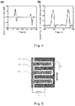
- Figs. 4(a) and 4(b) show the short circuit current and the quantity of the induced charges between two electrode layers, and the results show that the maximum short circuit current is 3 ⁇ A and the quantity of the induced charges is 75nC.
- the two electrode layers of the electricity generation component are patterned electrode layers.
- Fig. 5 is another typical structure of the generator according to the embodiment.
- the first electrode layer 210 and the second electrode layer 220 of the electricity conductive component form a mutual insertion arrangement.
- Each of the electrodes in the mutual insertion arrangement is formed by arranging several long strip-like sub-electrodes in parallel and connecting them to each other at one end thereof.
- the long strip-like sub-electrodes of the two electrodes are alternately arranged.
- a friction layer covers the electricity generation component so that the first electrode layer 210 and the second electrode layer 220 of the electricity generation component are isolated from the liquid environment in which the generator operates.
- a sub-electrode of the first electrode layer 210 and a sub-electrode of the second electrode layer 220 are adjacent to each other in the direction of fluctuation of the liquid and are separated by the interval 230 therebetween to form an electricity generation sub-component A1 similar to that in Example One in structure.
- the generator of such a structure may be applied in an environment in which the fluid fluctuates in a wide range.
- the electricity generation component in the generator in this embodiment includes a plurality of electricity generation sub-components as described in Example One in structure.
- the plurality of electricity generation sub-components are arranged in parallel and the adjacent electricity generation sub-components share a common long strip-like sub-electrode.
- the adjacent electricity generation sub-components A1 and A2 share a common long strip-like sub-electrode of the first electrode layer 210.
- a ratio of length to width of the long strip-like sub-electrodes in the first electrode layer or the second electrode layer in the mutual insertion arrangement is 1: 1 to 1000: 1.
- the width of the interval 230 between the first electrode layer 210 and the second electrode layer 220 is preferably 10nm to 5cm, and more preferably 0.1 ⁇ m to 1cm.
- the material and structure of the substrate and the friction layer may be the same as those in Example One.
- the material of the first electrode layer and the second electrode layer may also be the same as those in Example One, which will not be repeated here.
- the generators in Example One and Example Two are suitable to be used in an environment with fluctuation such as ocean wave fluctuation.
- the liquid fluctuates, the change of contact area of the generator with the liquid is limited, and the efficiency of absorption to mechanical energy of a flowing fluid such as rain water is restrained.
- the generator provided in this embodiment comprises a plurality of electricity generation components described in Example One and a plurality of rectifying devices of which the number is the same as that of the electricity generation components.
- the electrode layers of the plurality of electricity generation components are arranged in parallel in a direction of flow or fluctuation of the fluid and two adjacent electricity generation components share one electrode layer therebetween.
- Output electrical signal of one electricity generation component is rectified by one rectifying device. All output ends of rectifying devices are connected in parallel as output end of the generator.
- a generator comprising five electricity generation components is taken as an example to illustrate the structure of the embodiment of this disclosure. As shown in Fig. 6 , six strip-like electrode layers 201, 202, 203, 204, 205 and 206 are arranged in parallel on an insulating substrate (not shown).
- the electrode layers 201 and 201 of the first electricity generation component are respectively connected to the input ends of the rectifying device A1, the electrode layers 202 and 203 of the second electricity generation component are respectively connected to the input ends of the rectifying device A2, the electrode layers 203 and 204 of the third electricity generation component are respectively connected to the input ends of the rectifying device A3, the electrode layers 204 and 205 of the fourth electricity generation component are respectively connected to the input ends of the rectifying device A4 and the electrode layer 205 and 206 of the fifth electricity generation component are respectively connected to the input ends of the rectifying device A5.
- the output ends of the five rectifying devices A1, A2, A3, A4 and A5 are connected in parallel to form output ends of the generator.
- a load 401 can be connected between the output ends of the generator.
- the six long strip-like electrode layers 201, 202, 203, 204, 205 and 206 of the five electricity generation components are covered with a friction layer (not shown) so that the electricity generation components are isolated from the liquid environment in which they operate.
- a friction layer (not shown)
- a situation in which a continuous water stream flows over the friction layer of the generator is taken as an example.
- the liquid sequentially flows over the friction layer covering the electrode layers 201, 202, 203, 204, 205 and 206, the liquid frictionates with the friction layer such that the friction layer and the liquid carry respective charges.
- each of a plurality of rectifying devices is connected to one respective electricity generation component, such that the alternating current signal generated by the electricity generation component is converted into a direct current signal.
- the plurality of electricity generation components of the generator When the flowing fluid or the liquid-droplet slips over the friction layer of the generator, the plurality of electricity generation components of the generator generate electrical signals at the same time or at different time.
- the mechanical energy resulting from the flowing of the fluid or the slipping of the liquid-droplet may be collected and converted into electric energy.
- the generator in this embodiment not only can be widely arranged in a place where flow or fluctuation of the liquid occurs, such as river or coast, but also can be applied in a liquid-droplet environment such as rain environment.
- each of the electricity generation components are connected to a respective rectifying device and the output ends of the rectifying devices are connected in parallel.
- Each of the electricity generation components may be connected to a rectifying device, respectively, and the output signal of each electricity generation component is rectified into a direct current signal and is output independently rather than is connected in parallel.
- the width of the electrode layer of each electricity generation component is in a range of 10 ⁇ m-10cm.
- the width of the interval between the two electrode layers is preferably in a range of 10nm-5cm, and more preferably 0.1 ⁇ m-1cm.
- a particular generator is taken as an example hereinafter to illustrate that the generator of the present disclosure can collect the energy of the flowing liquid to generate electricity.
- An organic glass is used as a substrate.
- Six long strip-like Cu films arranged in parallel with equal interval which are used as electrode layers of five electricity generation components are deposited on the substrate of organic glass by means of a physical vapor deposition (PVD) method.
- PVD physical vapor deposition
- Each of the electrode layers has a length of 20 cm, a width of 6 cm and a thickness of 200 nm.
- Macromolecule polymer material FEP that is susceptible to accept electrons is used to prepare a friction layer.
- the friction layer made of FEP material and having a thickness of 75 microns is adhered onto the six parallel Cu film layers.
- Fig. 7 illustrates a short circuit current of the generator during a period from a moment at which the water stream is approaching to the first electrode layer to a moment at which the water stream completely leaves away from the electrode layers. It can be seen that there are two electricity generation processes for the generator of which each corresponds to one interaction between the generator and the water.
- the short circuit current output from the generator is approximately 8 ⁇ A.
- the generators according to various embodiments of the disclosure are simple in structure and are able to be arranged in a wide area so as to be used in an environment of lake, coast and the like.
- the generators can collect mechanical energy of fluctuation or flow of the water.
- the generator according to the disclosure may also be used in a small water area.
- the generator may be used in a water tank in which the water fluctuates or the generator moves when the tank swings, causing a fluctuation of the water relative to the generator such that mechanical energy of fluctuation of the water is converted into electric energy.
- the present disclosure also provides a method of generating electricity in liquid by means of any one of the generators described above.
- the method will be described in connection with Fig. 1 .
- the fluctuating or flowing liquid frictionates with the friction layer 30 of the generator such that the liquid carries charges.
- the charges on the surface of the friction layer corresponding to the two electrode layers of the electricity generation component are successively shielded by ions in the liquid as the liquid flows or fluctuates, causing the electrostatic effects of the charges carried on the surface of the friction layer on the electrons in the first electrode layer different from those on the electrons in the second electrode layer, which results in flow of charges between the first electrode layer 21 and the second electrode layer 22 through an outer circuit.
- the method provided in the present disclosure can be applied in fluctuating liquid and can also be applied in an environment such as lakes, rivers and the like. It is convenient to convert mechanical energy in liquid in various forms into electric energy according to the method of this disclosure.
Landscapes
- Physical Or Chemical Processes And Apparatus (AREA)
- Other Liquid Machine Or Engine Such As Wave Power Use (AREA)
Abstract
Description
- The present disclosure relates to a triboelectric nanogenerator, and in particular, to a triboelectric nanogenerator and a method of generating electricity that can convert fluctuation or flow energy of liquid into electric energy.
- Fluctuation or flow energy of liquid is ubiquitous in the environment. The main way of using fluctuation or flow energy of liquid to generate electricity at present is to provide a flexible piezoelectric material in a liquid, in particular a low-dimensional carbon nanostructure, such as carbon nanotubes and multi-layer graphene. The tape-like piezoelectric material fluctuates to generate potential under an effect of flow of a polar liquid. In existing designs, due to mechanical fatigue, this eel-like reciprocation causes difficulties for long-term operation of a device, and especially degrades the lives of the electrodes. This can be improved by restraining the material properties and ion concentration in water. However, these devices can only use the fluctuation energy of water that is in contact with the piezoelectric material, and can not take advantage of other energy that may be present in the water such as flow or fluctuation energy.
- A technical problem to be solved by the present disclosure is to design a new type of triboelectric nanogenerator used in a fluctuation or flowing liquid, which can convert mechanical energy collected from fluctuation or flow energy of liquid into electric energy. However, the structure of the generator can not be damaged due to the fluctuation or flow of liquid.
- To solve the above technical problem, a triboelectric nanogenerator that can convert mechanical energy collected from fluctuation or flow energy of liquid into electric energy is provided in the present disclosure. An electricity generation component of the generator comprises two electrode layers that are separately disposed; and a friction layer covering the electricity generation component, wherein the liquid can frictionate with the friction layer by each other when flowing or fluctuating, such that the surface of the friction layer carries friction charges. The charges on the surface of the friction layer corresponding to the two electrode layers are successively shielded by ions in the liquid as the liquid flows or fluctuates, causing the electrostatic effects of the charges carried on the surface of the friction layer on the electrons in the first electrode layer different from those on the electrons in the second electrode layer, which results in a flow of induced charges between the two electrode layers. The generator with such a structure does not require a change of the devices of the generator and the devices can operate stably for a long time. The two electrode layers are covered with the friction layer such that the electricity generation component will not be in contact with the liquid in the environment where the generator are used and thus the generator can be widely used in a variety of liquid environments.
- Based on the above concept, a triboelectric nanogenerator that collects mechanical energy of liquid is provided at first in the present disclosure, comprising:
- an insulating substrate;
- an electricity generation component that consists of a first electrode layer and a second electrode layer, wherein the first electrode layer and the second electrode layer are separately disposed on the substrate and electrically connected to each other; and
- a friction layer that covers the electricity generation component such that the first electrode layer and the second electrode layer of the electricity generation component are isolated from the liquid;
- wherein the liquid frictionates with the friction layer when the liquid fluctuates or flows, such that a surface of the friction layer in contact with the liquid carries charges. The charges on the surface of the friction layer corresponding to the two electrode layers are sequentially shielded by ions in the liquid as the liquid flows or fluctuates, causing the electrostatic effects of the charges carried on the surface of the friction layer on the electrons in the first electrode layer different from those on the electrons in the second electrode layer, which results in a flow of induced charges between the first electrode layer and the second electrode layer.
- Alternatively, the surface of the friction layer in contact with the liquid is provided with a microstructure layer which is made from any one of nanowires, nanotubes, nanoparticles, nanorods, nanoflowers, nanogrooves, micron grooves, nanotapers, micron tapers, nanospheres or micron spherical structure, or an array of the above structures.
- Alternatively, when the liquid is a polar liquid, the microstructure layer on the surface of the friction layer is a hydrophobic structure; or, when the liquid is a non-polar liquid, the microstructure layer on the surface of the friction layer is a hydrophilic structure.
- Alternatively, the first electrode layer and the second electrode layer both are long strip-like in shape, and are arranged in parallel on the substrate in the length direction.
- Alternatively, a ratio of length to width of the first electrode layer and/or the second electrode layer is 1: 1 to 1000: 1.
- Alternatively, a width of an interval between the first electrode layer and the second electrode layer is 10nm to 5cm.
- Alternatively, the friction layer is a film which has a thickness of 10nm to 2cm; and the microstructure layer has a thickness of 2nm to 200µm.
- Alternatively, the surface of the friction layer in contact with the liquid is chemically modified, wherein:
- material polarity of the friction layer is compared with material polarity of the liquid, and if the polarity of the friction layer is positive, a functional group that is more susceptible to donate electrons is introduced onto the surface of the friction layer; or if the polarity of the friction layer is negative, a functional group that is more susceptible to accept electrons is introduced onto the surface of the friction layer; or
- the material polarity of the friction layer is compared with the material polarity of the liquid, and if the polarity of the friction layer is positive, positive charges are introduced onto the surface of the friction layer; or if the polarity of the friction layer is negative, negative charges are introduced onto the surface of the varying layer.
- Alternatively, the material of the friction layer is one or more of the following materials: polytetrafluoroethylene, poly(perfluoroethylene-propylene) (FEP, copolymer of tetrafluoroethylene and hexafluoropropylene), polydimethylsiloxane (PDMS), polyimide, polydiphenyl propane carbonate, polyethylene glycol terephthalate, aniline-formaldehyde resin, polyformaldehyde, ethyl cellulose, polyamide, melamine-formaldehyde, polyethylene glycol succinate, cellulose, cellulose acetate, polyethylene glycol adipate, polydiallyl phthalate, regenerated cellulose sponge, polyurethane elastomer, styrene-propylene copolymer, styrene-acrylonitrile copolymer, styrene-butadiene copolymer, polyamide nylon 11, polyamide nylon 66, wool and fabrics thereof, silk and fabrics thereof, paper, artificial fiber, cotton and fabrics thereof, wood, hard rubber, polymethacrylate, polyvinyl alcohol, polyester, polyisobutylene, polyurethane elastomer, polyurethane flexible sponge, polyethylene glycol terephthalate, polyvinyl butyral, phenolic resin, chloroprene rubber, butadiene-propylene copolymer, natural rubber, polyacrylonitrile, poly(vinylidene chloride-co-acrylonitrile), polyethylene bisphenol A carbonate, polystyrene, polymethyl methacrylate, polycarbonate, liquid crystal polymer, polychloroprene, polyacrylonitrile, acetate, polybisphenol carbonate, polychloroether, polytrifluorochloroethylene, polyvinylidene chloride, polyethylene, polypropylene, polyvinyl chloride, and Parylene, including Parylene C, Parylene N, Parylene D, Parylene HT, or Parylene AF4.
- Alternatively, the first electrode layer and the second electrode layer in the electricity generation component have a same shape and a same size.
- Alternatively, the substrate, the electricity generation component and/or the friction layer are made of a rigid or flexible material.
- Alternatively, the liquid is water, deionized water, sea water, aqueous NaCl solution, formic acid, methanol, ethanol, n-propanol, isopropanol, n-butanol, acetic acid, dimethyl sulfoxide, dimethyl formamide, acetonitrile, acetone, hexane, benzene, toluene, diethyl ether, chloroform, ethyl acetate, tetrahydrofuran, or dichloromethane.
- Alternatively, the first electrode layer and the second electrode layer of the electricity generation component form a mutual insertion arrangement. Each of the electrodes in the mutual insertion arrangement is formed by arranging several long strip-like sub-electrodes in parallel and connecting them to each other at one end thereof. There is an interval between the first electrode layer and the second electrode layer in the mutual insertion arrangement and the first electrode layer and the second electrode layer are alternately arranged.
- Alternatively, a ratio of length to width of the long strip-like sub-electrodes is 1: 1 to 1000: 1.
- Alternatively, a width of the interval between the first electrode layer and the second electrode layer is 10nm-5cm.
- Alternatively, the generator comprises a plurality of electricity generation components, wherein the plurality of electricity generation components are arranged sequentially in a direction of fluctuation or flow of the liquid and two adjacent electricity generation components share one electrode layer therebetween.
- Alternatively, the generator further comprises a plurality of rectifying devices of which the number is the same as that of the electricity generation components, wherein the two electrode layers of each electricity generation component are connected to one of the rectifying devices.
- Alternatively, output ends of all of the rectifying devices are connected in parallel to form an output end of the generator.
- Alternatively, the rectifying devices are bridge rectifiers.
- Accordingly, a method of generating electricity by collecting mechanical energy of liquid by means of a generator described above is further provided in the present disclosure, wherein the fluctuating or flowing liquid and the friction layer of the generator frictionate with each other such that the surface of the friction layer carries charges. The charges on the surface of the friction layer corresponding to the two electrode layers of the electricity generation component are successively shielded by ions in the liquid as the liquid flows or fluctuates, causing the electrostatic effects of the charges carried on the surface of the friction layer on the electrons in the first electrode layer different from those on the electrons in the second electrode layer, which results in a flow of charges between the first electrode layer and the second electrode layer through an outer circuit.
- The triboelectric nanogenerator in present disclosure that collects mechanical energy, for example, in the form of fluctuation or flow energy of liquid provides advantages that it is not necessary for the two electrode layers of the electricity generation component to move as the liquid fluctuates, thereby ensuring the life of the generator. The electricity generation component is isolated from the liquid environment by the friction layer, which make it possible for the generator to be applied in any liquid environment, such as in ponds, rivers or the coast to collect the mechanical energy of the water wave. Meanwhile , the generator can also be used to collect the mechanical energy of raindrops.
- The performance of the generator can be further improved by adjusting the structure of the surface of the friction layer that is in contact with the liquid so that the surface has a hydrophobic structure which can increase the contact area between the friction layer and the liquid.
- The structure of the two electrode layers of the electricity generation component can be designed with a pattern such that the generator can be applied in the case of a small fluctuation of the liquid and can also be applied in the case of liquid-drop generation.
- The generator in the present disclosure provides characteristics of low weight, small size, simple structure, low cost and convenience for scale production and installation, and can be arranged in a wide area so as to be used in an environment of ponds, rivers or coasts, to collect mechanical energy such as fluctuation or flow energy of water stream.
- The above and other objects, features and advantages of the present disclosure will be more apparent with reference to the drawings. In the drawings, the similar reference numerals indicate the similar parts. The drawings are illustratively drawn and are not intended to be drawn in scale according to the actual size but to exhibit the concept of the disclosure. Further, although exemplary parameters provided herein may contain a specific value, it is not necessary for the parameters to be exactly equal to the corresponding value and the parameters may be similar to the corresponding values which are in acceptable tolerances or design constraints. Additionally, the directional terms mentioned in the following embodiments, such as "upper", "lower", "front", "rear", "left", "right" and the like, are only reference directions of the drawings. Thus, the directional terms herein are intended to illustrate rather than to limit the scope of the present disclosure.
-
Fig. 1 is a structurally schematic drawing of a triboelectric nanogenerator that collects mechanical energy of liquid according to the first embodiment of the present disclosure; -
Figs. 2a-c are schematic drawings showing the change of the charges on the surface of the friction layer after the contact friction and separation between the friction layer of the generator and the liquid; -
Figs. 3a-f are schematic drawings of the working process of a triboelectric nanogenerator that collects mechanical energy of liquid according to the present disclosure; -
Figs. 4 (a) and (b) are graphs of the short circuit current and the quantity of the induced charges when a particular generator operates; -
Fig. 5 is a structurally schematic drawing of a triboelectric nanogenerator according to the second embodiment of the present disclosure; -
Fig. 6 is a structurally schematic drawing of a triboelectric nanogenerator according to the third embodiment of the present disclosure; and -
Fig. 7 is a graph of the short circuit current when a particular generator operates. - The solution in the embodiment of the present disclosure will be clearly and completely described below in connection with the drawings in the embodiment of the present disclosure. It is apparent that the described embodiments are only a part of embodiments of the present disclosure rather than all of the embodiments. The other embodiments that can be obtained by an ordinary person skilled in the art without creative efforts based on the embodiments of the present disclosure will fall within the protection scope of the present disclosure.
- Further, the present disclosure is described in detail in conjunction to the schematic drawings. When the embodiments of the disclosure are described in detail, the schematic drawings are illustrative for a purpose of illustration, which is not intended to limit the scope of the disclosure.
-
Fig. 1 is a typical structure of a triboelectric nanogenerator according to the present disclosure comprising an insulating substrate10, an electricity generation component and afriction layer 30. The electricity generation component consists of afirst electrode layer 21 and asecond electrode layer 22, wherein thefirst electrode layer 12 and thesecond electrode layer 22 are separately disposed on thesubstrate 10 and electrically connected to each other. Thefriction layer 30 covers the electricity generation component such that thefirst electrode layer 12 and thesecond electrode layer 22 of the electricity generation component are isolated from the liquid environment in which the generator operates. The liquid fluctuates and frictionates with thefriction layer 30 such that the surface of thefriction layer 30 in contact with the liquid carries charges. The charges on the surface of thefriction layer 30 corresponding to the two electrode layers are successively shielded by ions in the liquid as the liquid fluctuates, causing the electrostatic effects of the charges carried on the surface of thefriction layer 30 on the electrons in thefirst electrode layer 21 different from those on the electrons in thesecond electrode layer 22, which results in a flow of induced charges between thefirst electrode layer 21 and thesecond electrode layer 22. A detection device or load 40 (as shown inFigs. 2a-c ) is connected between thefirst electrode layer 21 and thesecond electrode layer 22. There may be current flowing through the detection device andload 40. - The material of the friction layer 30 may be an insulating material, preferably an organic insulator material, which can be selected from the following materials: polytetrafluoroethylene, poly(perfluoroethylene-propylene) (FEP, copolymer of tetrafluoroethylene and hexafluoropropylene), polydimethylsiloxane (PDMS), polyimide, polydiphenyl propane carbonate, polyethylene glycol terephthalate, aniline-formaldehyde resin, polyformaldehyde, ethyl cellulose, polyamide, melamine-formaldehyde, polyethylene glycol succinate, cellulose, cellulose acetate, polyethylene glycol adipate, polydiallyl phthalate, regenerated cellulose sponge, polyurethane elastomer, styrene-propylene copolymer, styrene-acrylonitrile copolymer, styrene-butadiene copolymer, polyamide nylon 11, polyamide nylon 66, wool and fabrics thereof, silk and fabrics thereof, paper, artificial fiber, cotton and fabrics thereof, wood, hard rubber, polymethacrylate, polyvinyl alcohol, polyester, polyisobutylene, polyurethane elastomer, polyurethane flexible sponge, polyethylene glycol terephthalate, polyvinyl butyral, phenolic resin, chloroprene rubber, butadiene-propylene copolymer, natural rubber, polyacrylonitrile, poly(vinylidene chloride-co-acrylonitrile), polyethylene bisphenol A carbonate, polystyrene, polymethyl methacrylate, polycarbonate, liquid crystal polymer, polychloroprene, polyacrylonitrile, acetate, polybisphenol carbonate, polychloroether, polytrifluorochloroethylene, polyvinylidene chloride, polyethylene, polypropylene, polyvinyl chloride, and Parylene, including Parylene C, Parylene N, Parylene D, Parylene HT, or Parylene AF4.
- When the liquid fluctuates or flows and brings into contact with the outer surface of the
friction layer 30, surface charges with same quantity but opposite signs are generated on the surfaces of the liquid and thefriction layer 30 due to the different electron donating and accepting capability of the liquid and thefriction layer 30. Taking water as an example of the liquid and a FEP film as an example of the material of thefriction layer 30, as shown inFig. 2a-c , there are no charges on the surface of FEP friction layer in the initial state (as shown inFig. 2a ), and when the water fluctuates, thewater 50 frictionates with the FEP friction layer. Then thewater 50 in contact with the FEP friction layer carries positive charges and the surface of FEP friction layer carries negative charges with the same quantity as the positive charges due to a triboelectric effect (as shown inFig. 2b ). After the water leaves the FEP friction layer as the water fluctuates, the negative charges on the friction layer remain (as shown inFig. 2c ). The process shown inFigs. 2b-c are repeated when the water fluctuates again and brings into contact with the FEP friction layer. - The operating principle of the generator according to the embodiment is shown in
Figs. 3a-f . There is an interval between thefirst electrode 21 and thesecond electrode 22 of the electricity generation component and the two electrodes are electrically connected by aload 50. Thefriction layer 30 is made from FEP film, thefirst electrode layer 21 and thesecond electrode layer 22 both are Cu film, and the liquid environment is water. Two electrode layers of the electricity generation component are distributed in a up and down direction in which water fluctuates (corresponding to the up and down distribution of the two electrode layers inFigs. 3a-f ). The generator generates electricity through the up and down fluctuation of the water waves on the surface of the material offriction layer 30. The electricity generation process can be divided into two processes: a first process in which the water level rises and sequentially submerges thefirst electrode layer 21 and thesecond electrode layer 22; and a second process in which the water level falls and sequentially exposes thesecond electrode layer 22 and thefirst electrode layer 21 from the water level. In the first process, the water brings into contact with thefriction layer 30 such that the surface thereof carries positive charges. When the water rises and partially submerges thefirst electrode layer 21, the electrons in thesecond electrode layer 22 will be attracted to thefirst electrode layer 21 due to electrostatic induction, resulting in an increase of concentration of the negative charges in thefirst electrode layer 21. A current flows through the load 50 (as shown inFig. 3a ). When the water submerges the interval between the two electrode layers, the quantity of negative charges in thefirst electrode layer 21 will reach a maximum value, and there are no charges to flow through the load 50 (as shown inFig. 3b ). As the water continues to rise and partially submerges thesecond electrode layer 22, the electrons in thefirst electrode layer 21 will be attracted to thesecond electrode layer 22 due to the repulsion effect of the positive charges on the surface of the water wave such that the concentration of positive charges in thesecond electrode layer 22 reduces. Then, a current flows through the load 50 (as shown inFig. 3c ). When the surface of thesecond electrode layer 22 is completely submerged by the water, the positive charges in thesecond electrode layer 22 will be completely neutralized by electrons so that the upper and lower electrodes will not carry any charges (not shown here, and refer to the situation inFig. 2b .). In the second process, when the water level falls from the highest level, thesecond electrode layer 22 is gradually exposed out of the water such that its negative charges are attracted again to thefirst electrode layer 21, thereby increasing the concentration of the negative charges in the lower electrode. Then a current flows through the load 50 (as shown inFig. 3d ). When the water level falls to the interval between the two electrodes, the concentration of the negative charges in thefirst electrode layer 21 will reach a maximum value and there is no current to flow through the load 50 (as shown inFig. 3e ). When the water continues to fall, thefirst electrode layer 21 begins to be gradually exposed out of the water and the negative charges will be repulsed to flow back to thesecond electrode layer 22 due to electrostatic induction. Then, a current flows through the load 50 (as shown inFig. 3f ). When the water level falls below thefirst electrode layer 21 and exposes it out of the water completely, the positive charges in the upper electrode are completely neutralized by electrons so that the two electrodes will not carry any charges. The water goes up and down, and repetitively submerges or exposes thefirst electrode layer 21 and thesecond electrode layer 22, which causes an alternating current to flow through theload 50 in the outer circuit. - It is noted that the phrase of "the water rises and partially or completely submerges the
first electrode layer 21 and thesecond electrode layer 22" herein is not intended to indicate that the water directly contacts with and submerges the first electrode layer or the second electrode layer, but means that the friction layer corresponding to the first electrode layer or the second electrode layer (that is, the friction layer covering the first electrode layer or the second electrode layer) is submerged in the direction of fluctuation of the liquid such that part or entirety of the electrode layer is below the water level. In all the drawings for this embodiment, the direction of fluctuation of liquid such as water is a direction of up and down fluctuation. However, the generators according to all embodiments of the present disclosure can be applied in a liquid environment in which the liquid fluctuates in other directions, such as a substantially horizontal direction of fluctuation of the ocean waves in tide and ebb. - When the generator operates, the liquid fluctuates and a reciprocating sliding friction occurs between the liquid and the
friction layer 30 such that the surface of the liquid and the surface of thefriction layer 30 carry charges with opposite signs. The charges on the surface of thefriction layer 30 corresponding to the two electrode layers are successively shielded by ions in the liquid as the liquid fluctuates and successively submerges thefirst electrode layer 21 and thesecond electrode layer 22, causing the electrostatic effects of the charges carried on the surface of thefriction layer 30 on the electrons in thefirst electrode layer 21 different from those on the electrons in thesecond electrode layer 22, which results in a current in the outer circuit (as shown inFigs. 3a, c, d and e ). - The
friction layer 30 provides a friction surface for the triboelectric nanogenerator of the present disclosure. The selection of the material thereof is made primarily in consideration of the triboelectric property of the liquid environment where the generator will be used. In the present embodiment, in addition to the above-mentioned organic insulator materials, the material of the outer surface of thefriction layer 30 may also be selected from semiconductor materials. Conventional semiconductor materials include silicon, germanium; a Group III and Group V compound, such as gallium arsenide, gallium phosphide, and the like; a Group II and Group VI compound, such as cadmium sulfide, zinc sulfide, and the like; and a solid solution consisting of a Group III-Group V compound and a Group II-Group VI compound, such as gallium aluminum arsenide, gallium arsenic phosphide, and the like. In addition to the above-mentioned crystalline semiconductors, amorphous glass semiconductors, organic semiconductors, and the like are possible. Non-conductive oxides, semiconductive oxides, and complex oxides, such as oxides of manganese, chromium, iron and copper, also including silicon oxide, manganese oxide, chromium oxide, iron oxides, copper oxide, zinc oxide, BiO2 and Y2O3, also exhibit triboelectric characteristics, can form surface charges during friction with liquids, and thus can also be used as the friction layer of the present disclosure. Since the length of the present specification is limited, it is impossible to enumerate all applicable materials herein. Only some specific materials are listed herein, for providing reference for the readers. However, it is obvious that these specific materials may not become factors limiting the protection scope of the present disclosure, because those skilled in the art can easily select other similar materials according to the triboelectric properties possessed by these materials, under the teaching from the present disclosure. - It is found through experiments that, the larger the difference between the triboelectric properties of the materials at the surface where the
friction layer 30 and the fluctuating liquid come into contact with each other, is, the stronger the electric signal output by the generator is. Therefore, it is possible to select an appropriate material, according to the actual requirements, to prepare the outer surface of the friction layer, in order to achieve a better output effect. Preferable materials exhibiting negative-polarity triboelectric property include polystyrene, polyethylene, polypropylene, polydiphenyl propane carbonate, polyethylene glycol terephthalate, polyimide, polyvinyl chloride, polydimethylsiloxane, polytrifluorochloroethylene, and polytetrafluoroethylene, and Parylene, including Parylene C, Parylene N, Parylene D, Parylene HT, or Parylene AF4; and preferable materials exhibiting positive-polarity triboelectric property include aniline-formaldehyde resin, polyformaldehyde, ethyl cellulose, polyamide nylon 11, polyamide nylon 66, wool and fabrics thereof, silk and fabrics thereof, paper, polyethylene glycol succinate, cellulose, cellulose acetate, polyethylene glycol adipate, polydiallyl phthalate, regenerated cellulose sponge, cotton and fabrics thereof, polyurethane elastomer, styrene-acrylonitrile copolymer, styrene-butadiene copolymer, wood, hard rubber, acetate, artificial fiber, polymethyl methacrylate, polyvinyl alcohol, and polyester. The friction layer is not limited to be made from only one material, but may be made from one or more of the above-mentioned materials. - The surface of the
friction layer 30 can be physically modified such that the surface is provided with microstructure in order of micron or sub-micron to increase the contact area between thefriction layer 30 and the fluctuating liquid, thereby increasing the quantity of contact charges carried in the liquid. This can also be achieved by means of sprinkling or coating of nanomaterials. Microstructure layer is preferably formed by nanowires, nanotubes, nanoparticles, nanorods, nanoflowers, nanogrooves, micron grooves, nanotapers, micron tapers, nanospheres, micron spherical structure or an array of the above structures, and in particular a nano array made up of nanowires, nanotubes or nanorods. The size of each of such cells in microstructure layer array is on the order of nanometers to micrometers. The size and shape of cells in a specific micro nanostructure layer are not intended to limit the scope of the present application. The microstructure layer of the outer surface of thefriction layer 30 may be prepared on the surface of the friction layer by a process such as photoetching, chemical etching or plasma etching, or may be directly formed when preparing the friction layer material. - In addition to a function of further increasing the contact area between the out surface of the
friction layer 30 and the liquid, the microstructure layer of thefriction layer 30 can also function to adjust the hydrophobicity of thefriction layer 30 so as to control the degree of separation between the friction layer and the liquid after each contact. Accordingly, it is preferable that the microstructure layer of the outer surface of the friction layer is superhydrophobic nanostructures, such as zinc oxide, polytetrafluoroethylene, polydimethylsiloxane and other nanowire array structures, in particular a superhydrophobic nanostructure layer of a lotus leaf surface or insect foot, and the like. - Further, according to the polarity of the liquid in the environment where the generator is used, the hydrophilic or hydrophobic structure of the outer surface of the
friction layer 30 is selected to improve the degree of separation after the contact between the liquid and the outer surface of the friction layer such that the normal operation of the generator is ensured. Preferably, when the liquid is a polar liquid, the microstructure layer of the surface of thefriction layer 30 is a hydrophobic structure; alternatively, when the liquid is a non-polar liquid, the microstructure layer of the surface of thefriction layer 30 is a hydrophilic structure. The polar liquid may be water, formic acid, methanol, ethanol, n-propanol, isopropanol, n-butanol, acetic acid, dimethyl sulfoxide, dimethyl formamide, acetonitrile, acetone or the like; and a non-polar liquid may be hexane, benzene, toluene, diethyl ether, chloroform, ethyl acetate, tetrahydrofuran or dichloromethane. - The surface of the
friction layer 30 in contact with the liquid can also be chemically modified so as to further improve charge transfer quantity at the moment of contact, thereby increasing concentration of the contact charge and the output power of the generator. The methods of chemical modification can be divided into the following two types: - One method is to compare material polarity of the
friction layer 30 with the liquid that is in contact with thefriction layer 30, wherein if the polarity of the friction layer is positive, a functional group that is susceptible to donate electrons (i.e. strong electron-donating group) is introduced onto the surface of the friction layer; and if the polarity of the friction layer is negative, a functional group that is susceptible to accept electrons (i.e. strong electron-accepting group) is introduced onto the surface of the friction layer, both of which are able to further improve charge transfer quantity at the moment of contact with each other, thereby increasing the concentration of the friction charge and the output power of the generator. The strong electron-donating groups may include an amino group, a hydroxy group, an alkoxy group, and the like; and the strong electron-accepting groups may include an acyl group, a carboxyl group, a nitro group, a sulfonic acid group, and the like. The introduction of the functional groups can be carried out by using a conventional method, such as surface modification by plasma, or the like. For example, mixed gas of oxygen and nitrogen can generate plasma at a certain power, thereby introducing an amino group at the material surface of the friction layer. - Another method is to compare the material polarity of the
friction layer 30 with the liquid that is in contact with the friction layer, wherein if the polarity of the friction layer is positive, positive charges are introduced onto the surface of the friction layer; and if the polarity of the friction layer is negative, negative charges are introduced onto the material surface of the varying layer. In particular, this can be achieved by way of chemical bonding. For example, the surface of PDMS friction layer can be modified with tetraethyl orthosilicate (TEOS) by a sol-gel method so as to carry negative charges. According to the electron donating and accepting capability and the type of surface chemical bond of the friction layer material, those skilled in the art can select an appropriate modifying material to bond thereto in order to achieve the object of the present disclosure, and thus such modifications fall within the scope of the present disclosure. - In addition, the output performance of the generator according to the disclosure is related to the conductivity of the liquid. A lower ion concentration assists to form surface friction charges when the liquid contacts with the friction layer mutually. In particular applications, the charge mount can be adjusted depending on different friction layer materials to increase the quantity of the surface contact charges generated when the liquid contacts with the friction layer mutually, thereby improving the output performance of the generator. For example, NaCl can be added into the water to form a saturated NaCl water solution and the quantity of the induced charges will be reduced by 40% compared to that in natural water with other conditions unchanged.
- In addition to water and NaCl water solution, the liquid environment in which the generator of the present disclosure can be applied can also be deionized water, sea water, rain and the above-described polar or non-polar liquid environment.
- In the present disclosure, the microstructure layer of the
friction layer 30 and/or the outer surface of the friction layer is not intended to be limited to a hard material in the present disclosure, but a flexible material may be possible. This is because the hardness of the material does not affect the effect of the contact between thefriction layer 30 and the liquid and those skilled in the art can choose the material according to the actual situation. - The thickness of the
friction layer 30 has a significant impact on the performance of the generator of the present disclosure, but factors such as the strength of the friction layer, the hydrophobic effect and electricity generation efficiency should also be considered during preparation. The friction layer of the present disclosure is preferably a thin layer that has a thickness of 10nm to 2cm, preferably 100nm to 1cm, more preferably 1µm to 1mm. All the above thickness values are applicable in the present disclosure. The thickness of thefriction layer 10 is as thin as possible, but due to the limitations of the prior art, it is most preferably 1µm to 100µm. Preferably, the thickness of the microstructure layer is between 2nm and 200µm. - The thickness of the friction layer is not particularly prescribed. However, in order to improve the output performance of the generator, the thickness of the friction layer is preferably on the order of nanometer to micrometer.
- The electricity generation component in the present embodiment consists of two electrode layers. Common conductive materials can be used for the preparation of a conductive member. Such common conductive materials may for example be metal, organic conductor and conductive non-metallic material and the like, wherein the metal may be selected from gold, silver, platinum, aluminum, nickel, copper, titanium, chromium, selenium, or alloy of the above metals; and a conductive non-metallic material may be selected from indium tin oxide ITO, doped semiconductor or a conductive polymer material.
- The size and shape of the two electrode layers of the electricity generation component may be the same or may be different from each other. It is found by means of experiments that reducing the width of the electrode layer can improve output performance of the generator. Preferably, either the first electrode layer or the second electrode layer is long strip-like and is arranged in parallel in the length direction. The ratio of the length to the width is 1: 1 to 1000: 1.
- In the electricity generation component, the
first electrode layer 21 and thesecond electrode layer 22 are separately disposed, that is, it is necessary to maintain a gap between the two electrode layers. The existence of the gap is a key for the electrons to flow between the two electrode layers through anouter circuit 40 such as load or a detection device. Theoretical research and experimental comparison show that the smaller the interval between the electrode layers is, the more beneficial it is to increase the current density and power density of the output. Therefore, it is preferable to maintain a small interval between electrode layers, but the interval can not be too small taking into account factor of discharging. The interval is preferably 10nm to 5cm, and more preferably 0.1µm to 1cm. The separated electrode layer may be prepared on asubstrate 10 by means of selective coating technology or be directly prepared by cutting a conductive thin layer or sheet. The thickness of the two electrode layers has no impact on the performance of the generator. The two electrode layers may be films, sheets or block structures, which may be appropriately selected according to the use environment of the generator and the size of the generator. - The relative position of the
first electrode layer 21 and thesecond electrode layer 22 is not prescribed as long as the electrode layers are alternatively arranged forward and backward or up and down in the direction of fluctuation of the liquid. Thefirst electrode layer 21 and thesecond electrode layer 22 may be disposed in a same plane, be located in different planes, be parallel to each other or be formed at an angle. Preferably, thefirst electrode layer 21 and thesecond electrode layer 22 are disposed in a same plane in order to reduce the equivalent capacitance between the two electrode layers, thereby increasing the output voltage of the generator. - In order to increase the electrical signal output density while preventing a discharge between the electrode layers, a filling medium may fill the gap between the two electrode layers. The filling medium may be the same to or different from the insulating material of the friction layer. The filling medium may only fill the gap between the two electrode layers, but as shown in
Figs. 1 to 3 , may also be disposed around the periphery of two electrode layers as a support structure or a protection structure for the electrode layers. The filling medium may be a same material as the material of the insulating substrate. - The substrate, the electricity generation component and the friction layer of the generator may be hard materials or flexible materials. The hardness of the materials does not significantly affect the performance of electricity generation, but the application scope of the generator according to the present disclosure can be extended. The substrate material can be selected from substrate materials that is commonly used in a semiconductor device, preferably an insulating material, and more preferably organic insulator material such as acrylic plastic or the like.
- Further, the generator may have a flat plate structure, a cylindrical structure and the like as a whole. For example, a cylindrical generator may be attached to a buoy, wherein the first electrode layer and the second electrode layer of the electricity generation component may be annular in shape and arranged on the buoy in a vertical direction. The first electrode layer and the second electrode layer vertically float as the vertical floating of the buoy, converting the mechanical energy of fluctuation of the liquid into electric energy. Further, the substrate of the generator may be substituted by an insulating portion on the buoy and the electricity generation component may be disposed directly on the buoy.
- A particular generator structure is taken as an example to illustrate the output performance of the generator in fluctuating water. Two Cu films arranged in parallel are deposited on a FEP film with a thickness of 75 microns by means of a mask method. The two Cu films have a length of 6 cm and a width of 3 cm and are used as the first electrode layer and the second electrode layer. There is an interval of 1mm between the two Cu film electrode layers. The Cu films have a thickness of 200 nm. After the two electrode layers are led to outside via wires, a side of the FEP film on which the electrode layer is prepared is laminated on polyethylene terephthalate (PET) substrate. A detection device is connected to the wires led from the two electrode layers. The two electrode layers of the generator are controlled by a linear motor to be submerged into the water and rise above the water level sequentially (two processes as shown in
Fig. 3 ). The moving speed of the generator is 0.5m/s.Figs. 4(a) and 4(b) show the short circuit current and the quantity of the induced charges between two electrode layers, and the results show that the maximum short circuit current is 3µA and the quantity of the induced charges is 75nC. - In this embodiment, the two electrode layers of the electricity generation component are patterned electrode layers.
Fig. 5 is another typical structure of the generator according to the embodiment. Thefirst electrode layer 210 and thesecond electrode layer 220 of the electricity conductive component form a mutual insertion arrangement. Each of the electrodes in the mutual insertion arrangement is formed by arranging several long strip-like sub-electrodes in parallel and connecting them to each other at one end thereof. There is aninterval 230 between the first electrode layer and the second electrode layer in the mutual insertion arrangement and the first electrode layer and the second electrode layer are alternately arranged. As shown inFig. 5 , in the direction of fluctuation of the liquid indicated by the arrow, the long strip-like sub-electrodes of the two electrodes are alternately arranged. A friction layer covers the electricity generation component so that thefirst electrode layer 210 and thesecond electrode layer 220 of the electricity generation component are isolated from the liquid environment in which the generator operates. A sub-electrode of thefirst electrode layer 210 and a sub-electrode of thesecond electrode layer 220 are adjacent to each other in the direction of fluctuation of the liquid and are separated by theinterval 230 therebetween to form an electricity generation sub-component A1 similar to that in Example One in structure. The generator of such a structure may be applied in an environment in which the fluid fluctuates in a wide range. The electricity generation component in the generator in this embodiment includes a plurality of electricity generation sub-components as described in Example One in structure. The plurality of electricity generation sub-components are arranged in parallel and the adjacent electricity generation sub-components share a common long strip-like sub-electrode. For example, the adjacent electricity generation sub-components A1 and A2 share a common long strip-like sub-electrode of thefirst electrode layer 210. - Preferably, a ratio of length to width of the long strip-like sub-electrodes in the first electrode layer or the second electrode layer in the mutual insertion arrangement is 1: 1 to 1000: 1. The width of the
interval 230 between thefirst electrode layer 210 and thesecond electrode layer 220 is preferably 10nm to 5cm, and more preferably 0.1 µm to 1cm. - In this embodiment, the material and structure of the substrate and the friction layer may be the same as those in Example One. The material of the first electrode layer and the second electrode layer may also be the same as those in Example One, which will not be repeated here.
- The generators in Example One and Example Two are suitable to be used in an environment with fluctuation such as ocean wave fluctuation. When the liquid fluctuates, the change of contact area of the generator with the liquid is limited, and the efficiency of absorption to mechanical energy of a flowing fluid such as rain water is restrained. In order to be suitable to be used in a liquid environment such as flowing water or raindrops, the generator provided in this embodiment comprises a plurality of electricity generation components described in Example One and a plurality of rectifying devices of which the number is the same as that of the electricity generation components. The electrode layers of the plurality of electricity generation components are arranged in parallel in a direction of flow or fluctuation of the fluid and two adjacent electricity generation components share one electrode layer therebetween. Output electrical signal of one electricity generation component is rectified by one rectifying device. All output ends of rectifying devices are connected in parallel as output end of the generator. A generator comprising five electricity generation components is taken as an example to illustrate the structure of the embodiment of this disclosure. As shown in
Fig. 6 , six strip-like electrode layers 201, 202, 203, 204, 205 and 206 are arranged in parallel on an insulating substrate (not shown). The electrode layers 201 and 201 of the first electricity generation component are respectively connected to the input ends of the rectifying device A1, the electrode layers 202 and 203 of the second electricity generation component are respectively connected to the input ends of the rectifying device A2, the electrode layers 203 and 204 of the third electricity generation component are respectively connected to the input ends of the rectifying device A3, the electrode layers 204 and 205 of the fourth electricity generation component are respectively connected to the input ends of the rectifying device A4 and theelectrode layer load 401 can be connected between the output ends of the generator. The six long strip-like electrode layers 201, 202, 203, 204, 205 and 206 of the five electricity generation components are covered with a friction layer (not shown) so that the electricity generation components are isolated from the liquid environment in which they operate. A situation in which a continuous water stream flows over the friction layer of the generator is taken as an example. When the liquid sequentially flows over the friction layer covering the electrode layers 201, 202, 203, 204, 205 and 206, the liquid frictionates with the friction layer such that the friction layer and the liquid carry respective charges. The charges on the surface of the friction layer corresponding to each of the electrode layers are sequentially shielded by ions in the liquid as the liquid sequentially flows over the two electrode layers of each electricity generation component, causing the electrostatic effects of the charges carried on the surface of the friction layer on the electrons in the two corresponding electrode layers different from each other, which results in a flow of induced charges between the two corresponding electrodes. Since the directions of the generated current are opposite when the fluid flows towards and away from the electricity generation component, each of a plurality of rectifying devices is connected to one respective electricity generation component, such that the alternating current signal generated by the electricity generation component is converted into a direct current signal. When the flowing fluid or the liquid-droplet slips over the friction layer of the generator, the plurality of electricity generation components of the generator generate electrical signals at the same time or at different time. By rectifying the output signals of electricity generation components into direct current signals through the corresponding rectifying devices, respectively, and connecting them in parallel as the output signal of the generator, the mechanical energy resulting from the flowing of the fluid or the slipping of the liquid-droplet may be collected and converted into electric energy. Thus, the generator in this embodiment not only can be widely arranged in a place where flow or fluctuation of the liquid occurs, such as river or coast, but also can be applied in a liquid-droplet environment such as rain environment. - In this embodiment, it is preferable that the electrode layers of each of the electricity generation components are connected to a respective rectifying device and the output ends of the rectifying devices are connected in parallel. In other embodiments, there may be no rectifying device and a plurality of electricity generation components are connected in order so that each electricity generation component in the generator can operate independently. Each of the electricity generation components may be connected to a rectifying device, respectively, and the output signal of each electricity generation component is rectified into a direct current signal and is output independently rather than is connected in parallel.
- Preferably, the width of the electrode layer of each electricity generation component is in a range of 10µm-10cm. The width of the interval between the two electrode layers is preferably in a range of 10nm-5cm, and more preferably 0.1µm-1cm.
- A particular generator is taken as an example hereinafter to illustrate that the generator of the present disclosure can collect the energy of the flowing liquid to generate electricity.
- An organic glass is used as a substrate. Six long strip-like Cu films arranged in parallel with equal interval which are used as electrode layers of five electricity generation components are deposited on the substrate of organic glass by means of a physical vapor deposition (PVD) method. Each of the electrode layers has a length of 20 cm, a width of 6 cm and a thickness of 200 nm. There is an interval of 1mm between two adjacent electrode layers. Macromolecule polymer material FEP that is susceptible to accept electrons is used to prepare a friction layer. The friction layer made of FEP material and having a thickness of 75 microns is adhered onto the six parallel Cu film layers. After the six parallel Cu film layers are led out by wires, epoxy is coated on edge of the friction layer such that the six electrode layers are seated by means of the friction layer and the substrate, thereby isolating the electrode layers from the liquid environment to improve the water tightness of the generator devices. And on a surface of the FEP film that will be in contact with the liquid a nanowire array in a direction perpendicular to the surface is prepared by means of a plasma etching method, improving hydrophobicity of the surface of the FEP friction layer. As shown in
Fig. 5 , wires led from two adjacent electrode layers ( in one electricity generation component) are connected to a bridge rectifier, and output ends of the bridge rectifier 5 are connected in parallel to an ammeter. Water stream flows over the generator at an angle of 30a with respect to the friction layer of the generator. The friction layer frictionates with the water stream such that the surface of the friction layer carries charges. The charges on the surface of the friction layer corresponding to the two electrode layers are successively shielded by ions in the liquid stream, causing the electrostatic effects of the charges carried on the surface of the friction layer on the electrons in the two electrode layers different from each other.Fig. 7 illustrates a short circuit current of the generator during a period from a moment at which the water stream is approaching to the first electrode layer to a moment at which the water stream completely leaves away from the electrode layers. It can be seen that there are two electricity generation processes for the generator of which each corresponds to one interaction between the generator and the water. The short circuit current output from the generator is approximately 8µA. - The generators according to various embodiments of the disclosure are simple in structure and are able to be arranged in a wide area so as to be used in an environment of lake, coast and the like. The generators can collect mechanical energy of fluctuation or flow of the water. Further, the generator according to the disclosure may also be used in a small water area. For example, the generator may be used in a water tank in which the water fluctuates or the generator moves when the tank swings, causing a fluctuation of the water relative to the generator such that mechanical energy of fluctuation of the water is converted into electric energy.
- The present disclosure also provides a method of generating electricity in liquid by means of any one of the generators described above. The method will be described in connection with
Fig. 1 . The fluctuating or flowing liquid frictionates with thefriction layer 30 of the generator such that the liquid carries charges. The charges on the surface of the friction layer corresponding to the two electrode layers of the electricity generation component are successively shielded by ions in the liquid as the liquid flows or fluctuates, causing the electrostatic effects of the charges carried on the surface of the friction layer on the electrons in the first electrode layer different from those on the electrons in the second electrode layer, which results in flow of charges between thefirst electrode layer 21 and thesecond electrode layer 22 through an outer circuit. - The method provided in the present disclosure can be applied in fluctuating liquid and can also be applied in an environment such as lakes, rivers and the like. It is convenient to convert mechanical energy in liquid in various forms into electric energy according to the method of this disclosure.
- It should be noted that the embodiments described above are only preferable embodiments of the present disclosure and are not intended to limit the disclosure in any form. Many variants, modifications or equivalents to the solution of the present disclosure can be made by those skilled in the art from the method or technical contents disclosed in the present disclosure without departing from the protection scope of the present application. Therefore, any simple modifications or equivalent changes or variants to the embodiments described above according to technical concept of the present disclosure without departing from the contents of the solution of the disclosure should fall within the protection scope of the present application.
Claims (20)
- A triboelectric nanogenerator that collects mechanical energy of liquid, comprising:an insulating substrate;an electricity generation component that consists of a first electrode layer and a second electrode layer, wherein the first electrode layer and the second electrode layer are separately disposed on the substrate and electrically connected to each other; anda friction layer that covers the electricity generation component such that the first electrode layer and the second electrode layer of the electricity generation component are isolated from the liquid,wherein the liquid frictionates with the friction layer when the liquid fluctuates or flows, such that a surface of the friction layer in contact with the liquid carries charges, andwherein the charges on the surface of the friction layer corresponding to the two electrode layers are sequentially shielded by ions in the liquid as the liquid fluctuates or flows, causing the electrostatic effects of the charges carried on the surface of the friction layer on the electrons in the first electrode layer different from those on the electrons in the second electrode layer, which results in a flow of induced charges between the first electrode layer and the second electrode layer.
- The triboelectric nanogenerator according to claim 1,
wherein the surface of the friction layer in contact with the liquid is provided with a microstructure layer which is made from any one of nanowires, nanotubes, nanoparticles, nanorods, nanoflowers, nanogrooves, micron grooves, nanotapers, micron tapers, nanospheres or micron spherical structure, or an array of the above structures. - The triboelectric nanogenerator according to claim 2,
wherein when the liquid is a polar liquid, the microstructure layer on the surface of the friction layer is a hydrophobic structure; or when the liquid is a non-polar liquid, the microstructure layer on the surface of the friction layer is a hydrophilic structure. - The triboelectric nanogenerator according to any one of claims 1-3,
wherein the first electrode layer and the second electrode layer both are long strip-like in shape, and are arranged in parallel on the substrate in a lengthwise direction. - The triboelectric nanogenerator according to claim 4,
wherein a ratio of length to width of the first electrode layer and/or the second electrode layer is 1: 1 to 1000: 1. - The triboelectric nanogenerator according to claim 4 or 5,
wherein a width of an interval between the first electrode layer and the second electrode layer is 10nm to 5cm. - The triboelectric nanogenerator according to claim 2,
wherein the friction layer is a film which has a thickness of 10nm to 2cm; and wherein the microstructure layer has a thickness of 2nm to 200µm. - The triboelectric nanogenerator according to any one of claims 1-7,
wherein the surface of the friction layer in contact with the liquid is chemically modified, wherein:comparing material polarity between the friction layer and the liquid, wherein if the polarity of the friction layer is positive, a functional group that is susceptible to donate electrons is introduced onto the surface of the friction layer; and if the polarity of the friction layer is negative, a functional group that is susceptible to accept electrons is introduced onto the surface of the friction layer; orcomparing the material polarity between the friction layer and the liquid, wherein if the polarity of the friction layer is positive, positive charges are introduced onto the surface of the friction layer; and if the polarity of the friction layer is negative, negative charges are introduced onto the surface of the varying layer. - The triboelectric nanogenerator according to any one of claims 1-8,
wherein the material of the friction layer is one or more of the following materials: polytetrafluoroethylene, poly(perfluoroethylene-propylene) (FEP, copolymer of tetrafluoroethylene and hexafluoropropylene), polydimethylsiloxane (PDMS), polyimide, polydiphenyl propane carbonate, polyethylene glycol terephthalate, aniline-formaldehyde resin, polyformaldehyde, ethyl cellulose, polyamide, melamine-formaldehyde, polyethylene glycol succinate, cellulose, cellulose acetate, polyethylene glycol adipate, polydiallyl phthalate, regenerated cellulose sponge, polyurethane elastomer, styrene-propylene copolymer, styrene-acrylonitrile copolymer, styrene-butadiene copolymer, polyamide nylon 11, polyamide nylon 66, wool and fabrics thereof, silk and fabrics thereof, paper, artificial fiber, cotton and fabrics thereof, wood, hard rubber, polymethacrylate, polyvinyl alcohol, polyester, polyisobutylene, polyurethane elastomer, polyurethane flexible sponge, polyethylene glycol terephthalate, polyvinyl butyral, phenolic resin, chloroprene rubber, butadiene-propylene copolymer, natural rubber, polyacrylonitrile, poly(vinylidene chloride-co-acrylonitrile), polyethylene bisphenol A carbonate, polystyrene, polymethyl methacrylate, polycarbonate, liquid crystal polymer, polychloroprene, polyacrylonitrile, acetate, polybisphenol carbonate, polychloroether, polytrifluorochloroethylene, polyvinylidene chloride, polyethylene, polypropylene, polyvinyl chloride, and Parylene, including Parylene C, Parylene N, Parylene D, Parylene HT, or Parylene AF4. - The triboelectric nanogenerator according to any one of claims 1-9,
wherein the first electrode layer and the second electrode layer in the electricity generation component have a same shape and a same size. - The triboelectric nanogenerator according to any one of claims 1-10,
wherein the substrate, the electricity generation component and/or the friction layer are made of a rigid or flexible material. - The triboelectric nanogenerator according to any one of claims 1-11,
wherein the liquid is water, deionized water, sea water, aqueous NaCl solution, formic acid, methanol, ethanol, n-propanol, isopropanol, n-butanol, acetic acid, dimethyl sulfoxide, dimethyl formamide, acetonitrile, acetone, hexane, benzene, toluene, diethyl ether, chloroform, ethyl acetate, tetrahydrofuran, or dichloromethane. - The triboelectric nanogenerator according to any one of claims 1-3 and 7-12,
wherein the first electrode layer and the second electrode layer of the electricity generation component form a mutual insertion arrangement, each of the electrodes in the mutual insertion arrangement is formed by arranging a plurality of long strip-like sub-electrodes in parallel and connecting them to each other at one end thereof; and
wherein there is an interval between the first electrode layer and the second electrode layer in the mutual insertion arrangement and the first electrode layer and the second electrode layer are alternately arranged. - The triboelectric nanogenerator according to claim 13,
wherein ratios of length to width of the long strip-like sub-electrodes are 1: 1 to 1000: l. - The triboelectric nanogenerator according to claim 13 or 14,
wherein a width of the interval between the first electrode layer and the second electrode layer is 10nm to scum. - The triboelectric nanogenerator according to any one of claims 1-12,
wherein the generator comprises a plurality of electricity generation components, and
wherein the plurality of electricity generation components are arranged sequentially in a direction of fluctuation or flow of the liquid and two adjacent electricity generation components share one electrode layer therebetween. - The triboelectric nanogenerator according to claim 16,
wherein the generator further comprises a plurality of rectifying devices of which the number is the same as that of the electricity generation components, and
wherein the two electrode layers of each electricity generation component are connected to one of the rectifying devices. - The triboelectric nanogenerator according to claim 17,
wherein output ends of all of the rectifying devices are connected in parallel to form an output end of the generator. - The triboelectric nanogenerator according to claim 17 or 18,
wherein the rectifying devices are bridge rectifiers. - A method of generating electricity by collecting mechanical energy of liquid by means of a triboelectric nanogenerator according to any one of claims 1-19,
wherein the fluctuating or flowing liquid and the friction layer of the generator frictionate with each other such that the surface of the friction layer carries charges, and
wherein the charges on the surface of the friction layer corresponding to the two electrode layers of the electricity generation component are successively shielded by ions in the liquid as the liquid fluctuates or flows, causing the electrostatic effects of the charges carried on the surface of the friction layer on the electrons in the first electrode layer different from those on the electrons in the second electrode layer, which results in a flow of charges between the first electrode layer and the second electrode layer through an outer circuit.
Applications Claiming Priority (2)
| Application Number | Priority Date | Filing Date | Title |
|---|---|---|---|
| CN201410140195.XA CN104980060B (en) | 2014-04-09 | 2014-04-09 | Triboelectric nanogenerator for harvesting liquid mechanical energy and power generation method |
| PCT/CN2015/076161 WO2015154693A1 (en) | 2014-04-09 | 2015-04-09 | Triboelectric nanogenerator harvesting liquid mechanical energy and electricity generation method |
Publications (3)
| Publication Number | Publication Date |
|---|---|
| EP3131195A1 true EP3131195A1 (en) | 2017-02-15 |
| EP3131195A4 EP3131195A4 (en) | 2018-01-10 |
| EP3131195B1 EP3131195B1 (en) | 2020-05-06 |
Family
ID=54276236
Family Applications (1)
| Application Number | Title | Priority Date | Filing Date |
|---|---|---|---|
| EP15776720.3A Active EP3131195B1 (en) | 2014-04-09 | 2015-04-09 | Triboelectric nanogenerator harvesting liquid mechanical energy and electricity generation method |
Country Status (5)
| Country | Link |
|---|---|
| EP (1) | EP3131195B1 (en) |
| JP (1) | JP6193501B2 (en) |
| KR (1) | KR101893217B1 (en) |
| CN (1) | CN104980060B (en) |
| WO (1) | WO2015154693A1 (en) |
Cited By (5)
| Publication number | Priority date | Publication date | Assignee | Title |
|---|---|---|---|---|
| CN110163018A (en) * | 2018-05-30 | 2019-08-23 | 北京纳米能源与系统研究所 | A kind of signal recognition method and system from driving |
| US20200106371A1 (en) * | 2017-03-28 | 2020-04-02 | Nanyang Technological University | Wearable triboelectric generator for energy harvesting |
| EP4421483A1 (en) | 2023-02-27 | 2024-08-28 | Consejo Superior De Investigaciones Científicas | Self-powered triboelectric transductor device for drops and liquids |
| US12107516B2 (en) * | 2022-07-29 | 2024-10-01 | POSTECH Research and Business Development Foundation | Triboelectric generator using lubricant-infused surface controlled by magnetic field and method of manufacturing same |
| US12451820B1 (en) | 2023-04-25 | 2025-10-21 | Guangdong Ocean University | Turbulence-enhanced liquid-solid friction nano power generation device |
Families Citing this family (79)
| Publication number | Priority date | Publication date | Assignee | Title |
|---|---|---|---|---|
| US10439517B2 (en) | 2015-01-26 | 2019-10-08 | Georgia Tech Research Corporation | Triboelectric nanogenerator for harvesting energy from water |
| CN105423219A (en) * | 2015-12-16 | 2016-03-23 | 长安大学 | Hybrid energy street lamp capable of converting falling energy of raindrops and solar energy into electric energy |
| CN106899235B (en) * | 2015-12-21 | 2019-03-05 | 华中科技大学 | A kind of droplet flow power generation device and preparation method thereof |
| CN105958859B (en) * | 2016-03-04 | 2021-09-17 | 上海天轩科技发展有限公司 | Fluid dynamic nano generator |
| KR102010759B1 (en) * | 2016-03-08 | 2019-08-14 | 주식회사 엘지화학 | Display device |
| CN107311319B (en) * | 2016-04-27 | 2020-12-11 | 北京纳米能源与系统研究所 | A system for reducing biofouling on underwater surfaces of solid-phase objects |
| KR102581469B1 (en) | 2016-06-29 | 2023-09-21 | 삼성전자주식회사 | Energy harvester using triboelectricity and apparatus including the same |
| CN106005336B (en) * | 2016-07-11 | 2018-06-05 | 大连海事大学 | bionic robot fish |
| CN106655875A (en) * | 2016-10-19 | 2017-05-10 | 北京大学 | Stretchable friction power generator and preparation method thereof |
| CN107546829A (en) * | 2017-08-24 | 2018-01-05 | 北京科技大学 | A kind of automatically cleaning self-charging energy system and its manufacture method |
| LU100485B1 (en) * | 2017-10-19 | 2019-04-25 | Luxembourg Inst Science & Tech List | Triboelectric member with embossed honeycomb pattern |
| KR102213229B1 (en) * | 2017-11-22 | 2021-02-04 | 송찰스기석 | Triboelectric power generating device and method for preparing the same |
| CN107782406A (en) * | 2017-11-23 | 2018-03-09 | 大连海事大学 | A water level sensor based on triboelectric induction |
| CN107860437A (en) * | 2017-12-18 | 2018-03-30 | 大连海事大学 | A round tube liquid level sensor |
| KR101952533B1 (en) | 2018-03-13 | 2019-02-26 | 한양대학교 산학협력단 | Paper based triboelectric nanogenerator and the manufacturing method thereof |
| KR102316538B1 (en) | 2018-03-14 | 2021-10-25 | 한양대학교 산학협력단 | Triboelectric nanogenerator with capsule structure and the manufacturing method thereof |
| CN108444445B (en) * | 2018-03-15 | 2020-09-25 | 中国科学院兰州化学物理研究所 | A self-powered inclination sensor based on underwater bubble movement |
| CN109039143B (en) * | 2018-08-10 | 2019-10-29 | 青岛市资源化学与新材料研究中心 | Telescopic solid-liquid nano friction generator |
| CN109104137A (en) * | 2018-09-11 | 2018-12-28 | 江苏大学 | A kind of common pole-type power generator being collected simultaneously rainwater energy and solar energy |
| CN111049417B (en) * | 2018-10-12 | 2022-09-16 | 北京纳米能源与系统研究所 | A friction generator |
| CN109655520B (en) * | 2019-01-29 | 2021-09-28 | 重庆安标检测研究院有限公司 | Device and method for testing electrostatic safety performance of mining nonmetal material |
| JP7308509B2 (en) * | 2019-02-15 | 2023-07-14 | 国立大学法人東海国立大学機構 | generator |
| CN109687756B (en) * | 2019-02-21 | 2020-04-07 | 中国科学院兰州化学物理研究所 | Friction nano-generator based on biological membrane material and suitable for being used in high-humidity environment and preparation method and application thereof |
| CN111810371A (en) * | 2019-04-12 | 2020-10-23 | 天津大学 | A deceleration belt power generation system |
| CN111835224A (en) * | 2019-04-15 | 2020-10-27 | 北京纳米能源与系统研究所 | Conformal triboelectric nanogenerator monomer, conformal structure and independent collector |
| CN110138261B (en) * | 2019-05-29 | 2020-05-29 | 厦门大学 | A kind of electric generator based on electric double layer and its power generation method |
| KR102231172B1 (en) | 2019-06-19 | 2021-03-22 | 경희대학교 산학협력단 | Highly efficient triboelectric nanogenerators based on cotton |
| CN111307120B (en) * | 2019-07-22 | 2022-10-21 | 北京纳米能源与系统研究所 | A kind of sensor, measurement system of ocean wave spectrum and measurement method thereof |
| CN110432581B (en) * | 2019-08-09 | 2021-02-12 | 河南大学 | Electricity generation gasbag device and use this electricity generation gasbag's shoe-pad or sole |
| CN110572071B (en) * | 2019-09-17 | 2021-01-12 | 华南师范大学 | Power generation method and power generation device |
| US11239768B2 (en) * | 2019-10-24 | 2022-02-01 | City University Of Hong Kong | Liquid droplet powered electricity generator |
| KR102223743B1 (en) | 2019-11-07 | 2021-03-05 | 울산대학교 산학협력단 | Energy harvester using fluid based triboelectric generator |
| CN111277052A (en) * | 2019-11-13 | 2020-06-12 | 北京纳杰科技有限公司 | Power generation method |
| CN111087635A (en) * | 2019-12-26 | 2020-05-01 | 上海工程技术大学 | A PDMS@F-MOF composite film for triboelectric nanogenerator and its preparation method |
| CN111555653A (en) * | 2020-04-21 | 2020-08-18 | 北京致成生物医学科技有限公司 | Preparation method and device of super-hydrophobic liquid-solid contact friction nano generator |
| CN111525831B (en) * | 2020-04-29 | 2023-09-22 | 西北工业大学 | A self-storage woven nanogenerator device and preparation method |
| CN111604097B (en) * | 2020-06-02 | 2021-12-03 | 苏州大学 | Biochemical liquid drop reaction device and method based on friction nano generator |
| CN111758462B (en) * | 2020-07-03 | 2021-12-17 | 浙江大学 | Multifunctional power generation greenhouse cloth and preparation method thereof |
| CN111786595B (en) * | 2020-07-09 | 2022-08-02 | 浙江大学 | Novel direct current generator based on graphene/polar liquid/semiconductor dynamic diode and preparation method thereof |
| CN112095338B (en) * | 2020-09-14 | 2021-09-28 | 浙江大学 | Method for preparing friction nano generator by using fluorinated graphene coating and application of method |
| CN112388168A (en) * | 2020-11-22 | 2021-02-23 | 镇江绅芯易创智能科技有限公司 | Preparation process of self-powered flexible liquid drop sensor based on laser processing technology |
| CN112615560B (en) * | 2020-12-25 | 2021-11-26 | 厦门烨映电子科技有限公司 | Energy acquisition device for solid-liquid evaporation friction, preparation method and energy acquisition method |
| JP7606355B2 (en) * | 2021-01-28 | 2024-12-25 | 日産自動車株式会社 | Power generation unit |
| CN112964760B (en) * | 2021-02-09 | 2022-12-23 | 中国石油大学(华东) | A humidity monitoring and analysis system driven by a double-engine friction nanogenerator, its preparation method and application |
| CN113037128B (en) * | 2021-03-11 | 2022-04-19 | 中国科学院理化技术研究所 | Thermoacoustic driving liquid friction generator |
| CN113002458A (en) * | 2021-03-15 | 2021-06-22 | 大连民族大学 | Friction nanometer generator and battery hybrid power supply wireless tire pressure monitoring system |
| CN113027664B (en) * | 2021-03-23 | 2022-08-05 | 华中科技大学 | Wave energy recovery device and method based on electrochemical principle |
| CN113141125A (en) * | 2021-04-09 | 2021-07-20 | 清华大学 | High-power-density needle-shaped liquid-solid coupling nano generator |
| CN113791124A (en) * | 2021-05-20 | 2021-12-14 | 中国石油大学(华东) | NO driven by wind power friction nano generator2Gas monitoring system and preparation method and application thereof |
| CN113489122B (en) * | 2021-07-02 | 2023-02-28 | 西南大学 | Direct-current liquid drop generator and preparation method thereof |
| EP4142139A1 (en) | 2021-08-27 | 2023-03-01 | Consejo Superior de Investigaciones Científicas (CSIC) | Energy harvesting device and self-powered sensor using the same |
| CN114046220B (en) * | 2021-11-23 | 2024-02-02 | 北京纳米能源与系统研究所 | Power generation system and power generation method |
| JP7740701B2 (en) * | 2021-12-21 | 2025-09-17 | 学校法人 関西大学 | Charging Film and Triboelectric Generator |
| CN114337355A (en) * | 2022-01-12 | 2022-04-12 | 上海大学 | Tape type friction nano generator |
| CN114598183A (en) * | 2022-01-28 | 2022-06-07 | 南京航空航天大学 | A hydroelectric power generation and flow monitoring device based on hollow electrode structure |
| JP7799244B2 (en) * | 2022-04-08 | 2026-01-15 | 日産自動車株式会社 | power generation equipment |
| CN114744907A (en) * | 2022-04-12 | 2022-07-12 | 北京大学深圳研究生院 | Liquid drop generator and preparation method thereof |
| CN114844388B (en) * | 2022-04-22 | 2026-03-24 | 北京纳米能源与系统研究所 | Biomimetic triboelectric nanogenerator device for capturing water flow energy |
| CN115102423B (en) * | 2022-07-14 | 2024-03-29 | 北京纳米能源与系统研究所 | A water flow energy nano-power generation device, self-driven sensor and collection system |
| CN115514251A (en) * | 2022-09-25 | 2022-12-23 | 桂林理工大学 | Preparation method and application of a self-contained liquid-solid friction nanogenerator |
| CN115498916B (en) * | 2022-09-28 | 2024-12-13 | 中国科学院海洋研究所 | A friction nanogenerator with a multi-layer friction layer and its preparation and application |
| KR102843745B1 (en) * | 2022-11-03 | 2025-08-06 | 경희대학교 산학협력단 | Tumbler capable of displaying semi-permanent temperature |
| CN115800804A (en) * | 2022-11-25 | 2023-03-14 | 北京纳米能源与系统研究所 | Liquid drop friction nano generator and monitor and monitoring method thereof |
| CN115566926B (en) * | 2022-12-07 | 2023-03-21 | 中国科学院深海科学与工程研究所 | Mixed friction nano generator |
| KR102857921B1 (en) * | 2022-12-07 | 2025-09-10 | 한국기술교육대학교 산학협력단 | Polymer gel for triboelectric energy harvester containing plasticizer and triboelectric energy harvester containing the same |
| KR102790519B1 (en) * | 2023-03-10 | 2025-04-02 | 경희대학교 산학협력단 | Triboelectric enhancement liquid chemical groups on the liquid triboelectric property and boosting energy harvesting unit |
| JPWO2024232135A1 (en) * | 2023-05-10 | 2024-11-14 | ||
| CN116605380A (en) * | 2023-05-12 | 2023-08-18 | 上海电力大学 | Self-powered water life-saving alarm system |
| KR102925311B1 (en) * | 2023-07-31 | 2026-02-06 | 경희대학교 산학협력단 | Method for manufacturing triboelectric nanogenerator comprising transmittance-shifting element and triboelectric nanogenerator manufactured by the same |
| TWI862106B (en) * | 2023-08-25 | 2024-11-11 | 國立高雄大學 | DC power generation device, method for preparing DC power generation device, and electro-deposition system using DC power generation device |
| CN117108435A (en) * | 2023-08-30 | 2023-11-24 | 上海大学 | A buoy-type energy collector based on frictional power generation |
| CN117639544B (en) * | 2023-10-20 | 2024-05-24 | 广东海洋大学 | Electromagnetic and liquid-solid friction composite nano generator based on wave energy and power generation system |
| KR20250061883A (en) | 2023-10-30 | 2025-05-08 | 경희대학교 산학협력단 | Hybrid droplet-based electricity generator and method of operation thereof |
| KR102877475B1 (en) | 2023-10-30 | 2025-10-27 | 경희대학교 산학협력단 | Droplet-based electricity generator with high dielectric constant intermediate layer and method of operation thereof |
| KR102870560B1 (en) | 2023-10-30 | 2025-10-14 | 경희대학교 산학협력단 | Liquid electrode-based droplet-based electricity generator and its operating method |
| CN119041231B (en) * | 2024-08-20 | 2025-09-16 | 广西大学 | A method for deinking mixed office waste paper using TENG electrical treatment |
| CN118783808B (en) * | 2024-09-11 | 2025-10-31 | 重庆大学 | Direct-current friction nano generator adopting steel needle electrode and multi-element dielectric material, and manufacturing method and application thereof |
| CN119411404B (en) * | 2024-11-14 | 2025-10-31 | 西安工程大学 | Friction catalytic fabric loaded with polytetrafluoroethylene coating and application thereof |
| CN119954269B (en) * | 2025-01-25 | 2025-11-18 | 北京纳米能源与系统研究所 | Water pollutant degradation promoting device in contact with electro-catalysis and water pollution treatment method |
Family Cites Families (12)
| Publication number | Priority date | Publication date | Assignee | Title |
|---|---|---|---|---|
| US7294441B2 (en) * | 2003-12-31 | 2007-11-13 | Samsung Electronics Co., Ltd. | Method and apparatus for using a transfer assist layer in a tandem electrophotographic process utilizing adhesive toner transfer |
| JP5205193B2 (en) * | 2008-09-25 | 2013-06-05 | 三洋電機株式会社 | Static induction generator |
| CN201467006U (en) * | 2009-03-26 | 2010-05-12 | 华北电力大学 | A rotary friction generator |
| US8519677B2 (en) * | 2009-08-27 | 2013-08-27 | Asteism, Inc. | Electrostatic power harvesting |
| JP2011151944A (en) * | 2010-01-21 | 2011-08-04 | Panasonic Corp | Power generator |
| CN201607495U (en) * | 2010-02-11 | 2010-10-13 | 湖州师范学院 | A Measuring Device for Flowing Electricity of Insulating Liquid |
| US9178446B2 (en) * | 2011-08-30 | 2015-11-03 | Georgia Tech Research Corporation | Triboelectric generator |
| CN103368451B (en) * | 2013-01-28 | 2016-02-03 | 北京纳米能源与系统研究所 | A kind of sliding friction nano generator |
| KR101411337B1 (en) * | 2013-02-15 | 2014-06-25 | 전자부품연구원 | Apparatus having a stacked structure for energy converting using liquid |
| CN103368452B (en) * | 2013-03-08 | 2016-03-30 | 北京纳米能源与系统研究所 | Electrostatic pulse generator and DC pulse generator |
| CN103354429B (en) * | 2013-03-12 | 2015-09-16 | 北京纳米能源与系统研究所 | A kind of sliding friction nano generator and electricity-generating method |
| CN103337985B (en) * | 2013-07-12 | 2015-10-28 | 北京大学 | A kind of single mantle friction generator based on side-friction and preparation method thereof |
-
2014
- 2014-04-09 CN CN201410140195.XA patent/CN104980060B/en active Active
-
2015
- 2015-04-09 KR KR1020167031119A patent/KR101893217B1/en active Active
- 2015-04-09 JP JP2016537129A patent/JP6193501B2/en active Active
- 2015-04-09 WO PCT/CN2015/076161 patent/WO2015154693A1/en not_active Ceased
- 2015-04-09 EP EP15776720.3A patent/EP3131195B1/en active Active
Cited By (7)
| Publication number | Priority date | Publication date | Assignee | Title |
|---|---|---|---|---|
| US20200106371A1 (en) * | 2017-03-28 | 2020-04-02 | Nanyang Technological University | Wearable triboelectric generator for energy harvesting |
| US11658586B2 (en) * | 2017-03-28 | 2023-05-23 | Nanyang Technological University | Wearable triboelectric generator for energy harvesting |
| CN110163018A (en) * | 2018-05-30 | 2019-08-23 | 北京纳米能源与系统研究所 | A kind of signal recognition method and system from driving |
| CN110163018B (en) * | 2018-05-30 | 2022-10-25 | 北京纳米能源与系统研究所 | Self-driven signal identification method and system |
| US12107516B2 (en) * | 2022-07-29 | 2024-10-01 | POSTECH Research and Business Development Foundation | Triboelectric generator using lubricant-infused surface controlled by magnetic field and method of manufacturing same |
| EP4421483A1 (en) | 2023-02-27 | 2024-08-28 | Consejo Superior De Investigaciones Científicas | Self-powered triboelectric transductor device for drops and liquids |
| US12451820B1 (en) | 2023-04-25 | 2025-10-21 | Guangdong Ocean University | Turbulence-enhanced liquid-solid friction nano power generation device |
Also Published As
| Publication number | Publication date |
|---|---|
| EP3131195B1 (en) | 2020-05-06 |
| WO2015154693A1 (en) | 2015-10-15 |
| JP2016529868A (en) | 2016-09-23 |
| JP6193501B2 (en) | 2017-09-06 |
| KR20170002424A (en) | 2017-01-06 |
| CN104980060A (en) | 2015-10-14 |
| KR101893217B1 (en) | 2018-08-29 |
| CN104980060B (en) | 2017-05-10 |
| EP3131195A4 (en) | 2018-01-10 |
Similar Documents
| Publication | Publication Date | Title |
|---|---|---|
| EP3131195B1 (en) | Triboelectric nanogenerator harvesting liquid mechanical energy and electricity generation method | |
| CN103368452B (en) | Electrostatic pulse generator and DC pulse generator | |
| CN105099260B (en) | Combined generator, electricity-generating method and method for sensing based on working fluid | |
| KR101982691B1 (en) | Sliding frictional nano generator and power generation method | |
| CN108322083B (en) | Wave energy efficient power generation device based on friction nano-generator | |
| CN103780128B (en) | A kind of wind-force friction nanometer power generator | |
| CN104734565B (en) | A kind of generator and electricity-generating method for collecting working fluid energy | |
| EP2975758B1 (en) | Sliding frictional nano generator and power generation method | |
| CN104467514B (en) | Liquid-based friction generator, power generation method and sensor | |
| CN104682767B (en) | Rotary friction electricity nano generator and fluid velocity sensor based on single electrode | |
| CN103780127B (en) | A kind of friction nanometer power generator | |
| CN103368449B (en) | Nanometer electric generator utilizing sliding friction | |
| CN103780122B (en) | A sliding friction nanogenerator set | |
| CN104682766B (en) | Nano generator, generating set and electricity-generating method based on independent frictional layer | |
| CN109980985A (en) | Liquid solid contact electric friction nano generator | |
| CN105958858B (en) | A kind of double-layer wave shape hybridized nanometer generator | |
| CN103780132B (en) | A kind of pulse friction generator and triboelectricity method | |
| CN105099255B (en) | A kind of electricity generation system suitable for wavy liquid | |
| EP3133375B1 (en) | Sensor and power generator based on electrostatic induction, and sensing method and power generation method | |
| CN103780130B (en) | A kind of cantilever type impulse generator | |
| CN105091913A (en) | Sensor and sensing method based on electrostatic induction | |
| CN105099256A (en) | Generator and power generation method based on electrostatic induction | |
| CN103997253A (en) | Friction generating device comprising flexible flap face and generating method | |
| CN103780135B (en) | A kind of direct current friction electric generator | |
| CN110086377A (en) | Single electrode generator and its electricity-generating method based on electric double layer in solution |
Legal Events
| Date | Code | Title | Description |
|---|---|---|---|
| STAA | Information on the status of an ep patent application or granted ep patent |
Free format text: STATUS: THE INTERNATIONAL PUBLICATION HAS BEEN MADE |
|
| PUAI | Public reference made under article 153(3) epc to a published international application that has entered the european phase |
Free format text: ORIGINAL CODE: 0009012 |
|
| STAA | Information on the status of an ep patent application or granted ep patent |
Free format text: STATUS: REQUEST FOR EXAMINATION WAS MADE |
|
| 17P | Request for examination filed |
Effective date: 20160518 |
|
| AK | Designated contracting states |
Kind code of ref document: A1 Designated state(s): AL AT BE BG CH CY CZ DE DK EE ES FI FR GB GR HR HU IE IS IT LI LT LU LV MC MK MT NL NO PL PT RO RS SE SI SK SM TR |
|
| AX | Request for extension of the european patent |
Extension state: BA ME |
|
| DAV | Request for validation of the european patent (deleted) | ||
| DAX | Request for extension of the european patent (deleted) | ||
| A4 | Supplementary search report drawn up and despatched |
Effective date: 20171212 |
|
| RIC1 | Information provided on ipc code assigned before grant |
Ipc: H02N 1/04 20060101AFI20171206BHEP |
|
| GRAP | Despatch of communication of intention to grant a patent |
Free format text: ORIGINAL CODE: EPIDOSNIGR1 |
|
| STAA | Information on the status of an ep patent application or granted ep patent |
Free format text: STATUS: GRANT OF PATENT IS INTENDED |
|
| INTG | Intention to grant announced |
Effective date: 20200107 |
|
| GRAS | Grant fee paid |
Free format text: ORIGINAL CODE: EPIDOSNIGR3 |
|
| GRAA | (expected) grant |
Free format text: ORIGINAL CODE: 0009210 |
|
| STAA | Information on the status of an ep patent application or granted ep patent |
Free format text: STATUS: THE PATENT HAS BEEN GRANTED |
|
| AK | Designated contracting states |
Kind code of ref document: B1 Designated state(s): AL AT BE BG CH CY CZ DE DK EE ES FI FR GB GR HR HU IE IS IT LI LT LU LV MC MK MT NL NO PL PT RO RS SE SI SK SM TR |
|
| REG | Reference to a national code |
Ref country code: GB Ref legal event code: FG4D |
|
| REG | Reference to a national code |
Ref country code: CH Ref legal event code: EP Ref country code: AT Ref legal event code: REF Ref document number: 1268441 Country of ref document: AT Kind code of ref document: T Effective date: 20200515 |
|
| REG | Reference to a national code |
Ref country code: DE Ref legal event code: R096 Ref document number: 602015052316 Country of ref document: DE |
|
| REG | Reference to a national code |
Ref country code: IE Ref legal event code: FG4D |
|
| REG | Reference to a national code |
Ref country code: LT Ref legal event code: MG4D |
|
| REG | Reference to a national code |
Ref country code: NL Ref legal event code: MP Effective date: 20200506 |
|
| PG25 | Lapsed in a contracting state [announced via postgrant information from national office to epo] |
Ref country code: LT Free format text: LAPSE BECAUSE OF FAILURE TO SUBMIT A TRANSLATION OF THE DESCRIPTION OR TO PAY THE FEE WITHIN THE PRESCRIBED TIME-LIMIT Effective date: 20200506 Ref country code: NO Free format text: LAPSE BECAUSE OF FAILURE TO SUBMIT A TRANSLATION OF THE DESCRIPTION OR TO PAY THE FEE WITHIN THE PRESCRIBED TIME-LIMIT Effective date: 20200806 Ref country code: GR Free format text: LAPSE BECAUSE OF FAILURE TO SUBMIT A TRANSLATION OF THE DESCRIPTION OR TO PAY THE FEE WITHIN THE PRESCRIBED TIME-LIMIT Effective date: 20200807 Ref country code: IS Free format text: LAPSE BECAUSE OF FAILURE TO SUBMIT A TRANSLATION OF THE DESCRIPTION OR TO PAY THE FEE WITHIN THE PRESCRIBED TIME-LIMIT Effective date: 20200906 Ref country code: SE Free format text: LAPSE BECAUSE OF FAILURE TO SUBMIT A TRANSLATION OF THE DESCRIPTION OR TO PAY THE FEE WITHIN THE PRESCRIBED TIME-LIMIT Effective date: 20200506 Ref country code: FI Free format text: LAPSE BECAUSE OF FAILURE TO SUBMIT A TRANSLATION OF THE DESCRIPTION OR TO PAY THE FEE WITHIN THE PRESCRIBED TIME-LIMIT Effective date: 20200506 Ref country code: PT Free format text: LAPSE BECAUSE OF FAILURE TO SUBMIT A TRANSLATION OF THE DESCRIPTION OR TO PAY THE FEE WITHIN THE PRESCRIBED TIME-LIMIT Effective date: 20200907 |
|
| PG25 | Lapsed in a contracting state [announced via postgrant information from national office to epo] |
Ref country code: HR Free format text: LAPSE BECAUSE OF FAILURE TO SUBMIT A TRANSLATION OF THE DESCRIPTION OR TO PAY THE FEE WITHIN THE PRESCRIBED TIME-LIMIT Effective date: 20200506 Ref country code: RS Free format text: LAPSE BECAUSE OF FAILURE TO SUBMIT A TRANSLATION OF THE DESCRIPTION OR TO PAY THE FEE WITHIN THE PRESCRIBED TIME-LIMIT Effective date: 20200506 Ref country code: LV Free format text: LAPSE BECAUSE OF FAILURE TO SUBMIT A TRANSLATION OF THE DESCRIPTION OR TO PAY THE FEE WITHIN THE PRESCRIBED TIME-LIMIT Effective date: 20200506 Ref country code: BG Free format text: LAPSE BECAUSE OF FAILURE TO SUBMIT A TRANSLATION OF THE DESCRIPTION OR TO PAY THE FEE WITHIN THE PRESCRIBED TIME-LIMIT Effective date: 20200806 |
|
| REG | Reference to a national code |
Ref country code: AT Ref legal event code: MK05 Ref document number: 1268441 Country of ref document: AT Kind code of ref document: T Effective date: 20200506 |
|
| PG25 | Lapsed in a contracting state [announced via postgrant information from national office to epo] |
Ref country code: AL Free format text: LAPSE BECAUSE OF FAILURE TO SUBMIT A TRANSLATION OF THE DESCRIPTION OR TO PAY THE FEE WITHIN THE PRESCRIBED TIME-LIMIT Effective date: 20200506 Ref country code: NL Free format text: LAPSE BECAUSE OF FAILURE TO SUBMIT A TRANSLATION OF THE DESCRIPTION OR TO PAY THE FEE WITHIN THE PRESCRIBED TIME-LIMIT Effective date: 20200506 |
|
| PG25 | Lapsed in a contracting state [announced via postgrant information from national office to epo] |
Ref country code: ES Free format text: LAPSE BECAUSE OF FAILURE TO SUBMIT A TRANSLATION OF THE DESCRIPTION OR TO PAY THE FEE WITHIN THE PRESCRIBED TIME-LIMIT Effective date: 20200506 Ref country code: CZ Free format text: LAPSE BECAUSE OF FAILURE TO SUBMIT A TRANSLATION OF THE DESCRIPTION OR TO PAY THE FEE WITHIN THE PRESCRIBED TIME-LIMIT Effective date: 20200506 Ref country code: SM Free format text: LAPSE BECAUSE OF FAILURE TO SUBMIT A TRANSLATION OF THE DESCRIPTION OR TO PAY THE FEE WITHIN THE PRESCRIBED TIME-LIMIT Effective date: 20200506 Ref country code: EE Free format text: LAPSE BECAUSE OF FAILURE TO SUBMIT A TRANSLATION OF THE DESCRIPTION OR TO PAY THE FEE WITHIN THE PRESCRIBED TIME-LIMIT Effective date: 20200506 Ref country code: RO Free format text: LAPSE BECAUSE OF FAILURE TO SUBMIT A TRANSLATION OF THE DESCRIPTION OR TO PAY THE FEE WITHIN THE PRESCRIBED TIME-LIMIT Effective date: 20200506 Ref country code: AT Free format text: LAPSE BECAUSE OF FAILURE TO SUBMIT A TRANSLATION OF THE DESCRIPTION OR TO PAY THE FEE WITHIN THE PRESCRIBED TIME-LIMIT Effective date: 20200506 Ref country code: DK Free format text: LAPSE BECAUSE OF FAILURE TO SUBMIT A TRANSLATION OF THE DESCRIPTION OR TO PAY THE FEE WITHIN THE PRESCRIBED TIME-LIMIT Effective date: 20200506 Ref country code: IT Free format text: LAPSE BECAUSE OF FAILURE TO SUBMIT A TRANSLATION OF THE DESCRIPTION OR TO PAY THE FEE WITHIN THE PRESCRIBED TIME-LIMIT Effective date: 20200506 |
|
| REG | Reference to a national code |
Ref country code: DE Ref legal event code: R097 Ref document number: 602015052316 Country of ref document: DE |
|
| PG25 | Lapsed in a contracting state [announced via postgrant information from national office to epo] |
Ref country code: PL Free format text: LAPSE BECAUSE OF FAILURE TO SUBMIT A TRANSLATION OF THE DESCRIPTION OR TO PAY THE FEE WITHIN THE PRESCRIBED TIME-LIMIT Effective date: 20200506 Ref country code: SK Free format text: LAPSE BECAUSE OF FAILURE TO SUBMIT A TRANSLATION OF THE DESCRIPTION OR TO PAY THE FEE WITHIN THE PRESCRIBED TIME-LIMIT Effective date: 20200506 |
|
| PLBE | No opposition filed within time limit |
Free format text: ORIGINAL CODE: 0009261 |
|
| STAA | Information on the status of an ep patent application or granted ep patent |
Free format text: STATUS: NO OPPOSITION FILED WITHIN TIME LIMIT |
|
| 26N | No opposition filed |
Effective date: 20210209 |
|
| PG25 | Lapsed in a contracting state [announced via postgrant information from national office to epo] |
Ref country code: SI Free format text: LAPSE BECAUSE OF FAILURE TO SUBMIT A TRANSLATION OF THE DESCRIPTION OR TO PAY THE FEE WITHIN THE PRESCRIBED TIME-LIMIT Effective date: 20200506 |
|
| PG25 | Lapsed in a contracting state [announced via postgrant information from national office to epo] |
Ref country code: MC Free format text: LAPSE BECAUSE OF FAILURE TO SUBMIT A TRANSLATION OF THE DESCRIPTION OR TO PAY THE FEE WITHIN THE PRESCRIBED TIME-LIMIT Effective date: 20200506 |
|
| PG25 | Lapsed in a contracting state [announced via postgrant information from national office to epo] |
Ref country code: LU Free format text: LAPSE BECAUSE OF NON-PAYMENT OF DUE FEES Effective date: 20210409 |
|
| REG | Reference to a national code |
Ref country code: BE Ref legal event code: MM Effective date: 20210430 |
|
| PG25 | Lapsed in a contracting state [announced via postgrant information from national office to epo] |
Ref country code: LI Free format text: LAPSE BECAUSE OF NON-PAYMENT OF DUE FEES Effective date: 20210430 Ref country code: CH Free format text: LAPSE BECAUSE OF NON-PAYMENT OF DUE FEES Effective date: 20210430 |
|
| PG25 | Lapsed in a contracting state [announced via postgrant information from national office to epo] |
Ref country code: IE Free format text: LAPSE BECAUSE OF NON-PAYMENT OF DUE FEES Effective date: 20210409 |
|
| PG25 | Lapsed in a contracting state [announced via postgrant information from national office to epo] |
Ref country code: BE Free format text: LAPSE BECAUSE OF NON-PAYMENT OF DUE FEES Effective date: 20210430 |
|
| PG25 | Lapsed in a contracting state [announced via postgrant information from national office to epo] |
Ref country code: HU Free format text: LAPSE BECAUSE OF FAILURE TO SUBMIT A TRANSLATION OF THE DESCRIPTION OR TO PAY THE FEE WITHIN THE PRESCRIBED TIME-LIMIT; INVALID AB INITIO Effective date: 20150409 |
|
| PG25 | Lapsed in a contracting state [announced via postgrant information from national office to epo] |
Ref country code: CY Free format text: LAPSE BECAUSE OF FAILURE TO SUBMIT A TRANSLATION OF THE DESCRIPTION OR TO PAY THE FEE WITHIN THE PRESCRIBED TIME-LIMIT Effective date: 20200506 |
|
| PG25 | Lapsed in a contracting state [announced via postgrant information from national office to epo] |
Ref country code: MK Free format text: LAPSE BECAUSE OF FAILURE TO SUBMIT A TRANSLATION OF THE DESCRIPTION OR TO PAY THE FEE WITHIN THE PRESCRIBED TIME-LIMIT Effective date: 20200506 |
|
| PG25 | Lapsed in a contracting state [announced via postgrant information from national office to epo] |
Ref country code: TR Free format text: LAPSE BECAUSE OF FAILURE TO SUBMIT A TRANSLATION OF THE DESCRIPTION OR TO PAY THE FEE WITHIN THE PRESCRIBED TIME-LIMIT Effective date: 20200506 |
|
| PG25 | Lapsed in a contracting state [announced via postgrant information from national office to epo] |
Ref country code: MT Free format text: LAPSE BECAUSE OF FAILURE TO SUBMIT A TRANSLATION OF THE DESCRIPTION OR TO PAY THE FEE WITHIN THE PRESCRIBED TIME-LIMIT Effective date: 20200506 |
|
| PGFP | Annual fee paid to national office [announced via postgrant information from national office to epo] |
Ref country code: DE Payment date: 20250428 Year of fee payment: 11 |
|
| PGFP | Annual fee paid to national office [announced via postgrant information from national office to epo] |
Ref country code: FR Payment date: 20250424 Year of fee payment: 11 |
|
| PGFP | Annual fee paid to national office [announced via postgrant information from national office to epo] |
Ref country code: GB Payment date: 20260227 Year of fee payment: 12 |