EP3131184A1 - Radnabenmotorvorrichtung für ein elektrofahrrad - Google Patents
Radnabenmotorvorrichtung für ein elektrofahrrad Download PDFInfo
- Publication number
- EP3131184A1 EP3131184A1 EP14888625.2A EP14888625A EP3131184A1 EP 3131184 A1 EP3131184 A1 EP 3131184A1 EP 14888625 A EP14888625 A EP 14888625A EP 3131184 A1 EP3131184 A1 EP 3131184A1
- Authority
- EP
- European Patent Office
- Prior art keywords
- gear
- spindle
- clutch
- secured
- outer ring
- Prior art date
- Legal status (The legal status is an assumption and is not a legal conclusion. Google has not performed a legal analysis and makes no representation as to the accuracy of the status listed.)
- Withdrawn
Links
Images


Classifications
-
- H—ELECTRICITY
- H02—GENERATION; CONVERSION OR DISTRIBUTION OF ELECTRIC POWER
- H02K—DYNAMO-ELECTRIC MACHINES
- H02K7/00—Arrangements for handling mechanical energy structurally associated with dynamo-electric machines, e.g. structural association with mechanical driving motors or auxiliary dynamo-electric machines
- H02K7/08—Structural association with bearings
- H02K7/083—Structural association with bearings radially supporting the rotary shaft at both ends of the rotor
-
- B—PERFORMING OPERATIONS; TRANSPORTING
- B62—LAND VEHICLES FOR TRAVELLING OTHERWISE THAN ON RAILS
- B62M—RIDER PROPULSION OF WHEELED VEHICLES OR SLEDGES; POWERED PROPULSION OF SLEDGES OR SINGLE-TRACK CYCLES; TRANSMISSIONS SPECIALLY ADAPTED FOR SUCH VEHICLES
- B62M11/00—Transmissions characterised by the use of interengaging toothed wheels or frictionally-engaging wheels
- B62M11/04—Transmissions characterised by the use of interengaging toothed wheels or frictionally-engaging wheels of changeable ratio
- B62M11/14—Transmissions characterised by the use of interengaging toothed wheels or frictionally-engaging wheels of changeable ratio with planetary gears
- B62M11/16—Transmissions characterised by the use of interengaging toothed wheels or frictionally-engaging wheels of changeable ratio with planetary gears built in, or adjacent to, the ground-wheel hub
-
- B—PERFORMING OPERATIONS; TRANSPORTING
- B62—LAND VEHICLES FOR TRAVELLING OTHERWISE THAN ON RAILS
- B62M—RIDER PROPULSION OF WHEELED VEHICLES OR SLEDGES; POWERED PROPULSION OF SLEDGES OR SINGLE-TRACK CYCLES; TRANSMISSIONS SPECIALLY ADAPTED FOR SUCH VEHICLES
- B62M11/00—Transmissions characterised by the use of interengaging toothed wheels or frictionally-engaging wheels
- B62M11/04—Transmissions characterised by the use of interengaging toothed wheels or frictionally-engaging wheels of changeable ratio
- B62M11/14—Transmissions characterised by the use of interengaging toothed wheels or frictionally-engaging wheels of changeable ratio with planetary gears
- B62M11/18—Transmissions characterised by the use of interengaging toothed wheels or frictionally-engaging wheels of changeable ratio with planetary gears with a plurality of planetary gear units
-
- B—PERFORMING OPERATIONS; TRANSPORTING
- B62—LAND VEHICLES FOR TRAVELLING OTHERWISE THAN ON RAILS
- B62M—RIDER PROPULSION OF WHEELED VEHICLES OR SLEDGES; POWERED PROPULSION OF SLEDGES OR SINGLE-TRACK CYCLES; TRANSMISSIONS SPECIALLY ADAPTED FOR SUCH VEHICLES
- B62M6/00—Rider propulsion of wheeled vehicles with additional source of power, e.g. combustion engine or electric motor
- B62M6/40—Rider propelled cycles with auxiliary electric motor
- B62M6/60—Rider propelled cycles with auxiliary electric motor power-driven at axle parts
- B62M6/65—Rider propelled cycles with auxiliary electric motor power-driven at axle parts with axle and driving shaft arranged coaxially
-
- H—ELECTRICITY
- H02—GENERATION; CONVERSION OR DISTRIBUTION OF ELECTRIC POWER
- H02K—DYNAMO-ELECTRIC MACHINES
- H02K7/00—Arrangements for handling mechanical energy structurally associated with dynamo-electric machines, e.g. structural association with mechanical driving motors or auxiliary dynamo-electric machines
- H02K7/10—Structural association with clutches, brakes, gears, pulleys or mechanical starters
- H02K7/116—Structural association with clutches, brakes, gears, pulleys or mechanical starters with gears
-
- H—ELECTRICITY
- H02—GENERATION; CONVERSION OR DISTRIBUTION OF ELECTRIC POWER
- H02K—DYNAMO-ELECTRIC MACHINES
- H02K7/00—Arrangements for handling mechanical energy structurally associated with dynamo-electric machines, e.g. structural association with mechanical driving motors or auxiliary dynamo-electric machines
- H02K7/14—Structural association with mechanical loads, e.g. with hand-held machine tools or fans
Definitions
- the present invention relates to a hub motor, which is applicable to an electromobile, especially an electric bike.
- An existing ordinary hub motor generally comprises a spindle, a wound stator, a rotor, a sun gear, a reduction assembly, a hub shell, a planetary reduction mechanism, a unidirectional clutch and other components, referring to Chinese utility model patent No. ZL201220268825.8 for its detailed structure.
- the wound stator and the rotor When the motor is energized to work, the wound stator and the rotor generate power source to drive the rotor to rotate, and the rotor gear on the rotor drives the planetary reduction system and the unidirectional clutch to rotate, which transmit torque to the hub directly via an inner gear ring secured on the hub to make the hub rotate.
- the planetary reduction mechanism used in such a hub motor has shortcomings of small reduction ratio and output torque.
- a traditional hub motor limited by its function and structure, can only be used in conjunction with an external gearbox, has complex appearance, is unesthetic, has interior space unreasonably used, and cannot be implanted into an internal transmission system to better drive the electric bike.
- a purpose of the present invention is to provide a hub motor that has a large output torque and an internal transmission function, so as to solve the above problems.
- An electric-bike hub motor means comprising a horizontally arranged spindle, a hub shell that is rotatably mounted outside the spindle, a stator and a rotor arranged inside the hub shell, and a gear speed reduction mechanism, wherein the stator is secured on the spindle;
- the gear speed reduction mechanism comprises a rotor gear that is secured to the rotor and arranged coaxially outside the spindle, a planetary carrier that is secured on the hub shell and sleeved outside the spindle, a planetary shaft that goes rotatably through the planetary carrier, a left planetary gear and a right planetary gear that are secured on the planetary shaft, and a sun gear that is secured and sleeved on the spindle, wherein the left planetary gear engages with the rotor gear, and the right planetary gear engages with the sun gear.
- the sun gear is a unidirectional clutch that has a clutch inner ring and a clutch outer ring locked unidirectionally thereto, wherein the clutch inner ring is secured to the spindle, and an outer gear ring engaging with the right planetary gear is provided on the clutch outer ring.
- the outer gear ring is integrated with the clutch outer ring.
- the planetary shaft is provided with at least two right planetary gears that are different in diameter;
- the clutch outer ring is provided with a plurality of outer gear rings engaging in one-to-one correspondence with the respective right planetary gears, with these outer gear rings sleeved rotatably circumferentially around and secured axially to the clutch outer ring; and a locking mechanism is also provided between the clutch outer ring and the outer gear ring that can secure them both together circumferentially.
- the clutch outer ring extends at its right end out of the hub shell and has a chain wheel, and a second unidirectional clutch is provided between the rotor gear and the spindle.
- the locking mechanism comprises a sliding bush that can be slidably sleeved axially on the spindle, and a sliding positioning means that is used to drive the sliding bush to slide axially on the spindle and can position the sliding bush axially on the spindle, with the sliding bush housed in the clutch outer ring;
- the clutch outer ring is provided in a position corresponding to each of the outer gear rings with a radial through hole, where a leaf spring locked on the clutch outer ring is provided;
- the leaf spring is provided outside with a roller that is locked thereto, and is provided inside with a ball that is located in the radial through hole and can be moved radially along the same;
- the outer gear ring is provided with a fit groove corresponding to the roller;
- the sliding bush is provided with a rim that, when the sliding bush slides axially on the spindle, can be moved outward along the radial through hole by abutting the ball and then press the leaf spring to deform it, such
- the sliding positioning means comprises a setting bolt spring sleeved on the spindle and sandwiched between the spindle and the sliding bush, a central axle hole provided on the spindle, a thimble arranged in the central axle hole and connected with the sliding bush, and a paddle that is fitted in contact with the thimble and used for toggling the thimble to make it move axially in the central axle hole, with the paddle connected in transmission with a gear change hand lever on the electric-bike handlebar through a transmission line.
- the sliding positioning means is an electromagnetic valve.
- a secondary planetary gear smaller than the respective right planetary gears in diameter is also fixed on the planetary shaft, and a secondary outer gear ring engaging with the secondary planetary gear is sleeved on the clutch outer ring, with the secondary outer gear ring connected to the clutch outer ring through a third unidirectional clutch.
- a supporting bearing which has relatively rotatable bearing inner ring and bearing outer ring, the sliding bush being axially slidably sleeved on the bearing outer ring, the bearing inner ring being secured on the spindle.
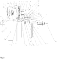
- a spindle 2. a hub shell; 2a. a shell body; 2b. a shell end cover; 3. a stator; 4. a rotor; 5. a rotor gear; 6. a planetary carrier; 7. a planetary shaft; 8. a left planetary gear; 9. a right planetary gear; 10. a sun gear; 10a. a clutch inner ring; 10b. a clutch outer ring; 10c. an outer gear ring; 10d. a secondary outer gear ring; 11. a second unidirectional clutch; 12. a chain wheel; 13. a third unidirectional clutch; 13. a swivel gear; 14. a sliding bush; 14a. a rim; 15. a roller; 16. a thimble; 17. a setting bolt spring; 18. a central axle hole; 19. an external gearbox; 20. a secondary planetary gear; and 22. a leaf spring.
- Fig. 1 shows a specific example of this electric-bike hub motor means of the present invention, which comprises a horizontally arranged spindle 1 provided with a hub shell 2, with the hub shell 2 able to be rotated around this spindle through a bearing (not labeled in the drawing) and composed of a shell body 2a and a shell end cover 2b secured to each other.
- the hub shell 2 is provided inside with a stator 3, a rotor 4 and a gear speed reduction mechanism, wherein the stator is secured on the spindle 1, with an outer-rotor inner-stator structure adopted in this example.
- the motor While in operation, the motor is energized to make the rotor 4 rotate counterclockwise in the right viewing direction shown in Fig. 1 , and the rotor 4 drives the rotor gear 5 to rotate counterclockwise around the spindle 1 and then transmits the rotation torque of the motor to the planetary carrier 6, making the planetary carrier 6 and the hub shell 2 rotate clockwise together around the spindle 1, then driving the electric bike to go forward, with the right planetary gear 9 rotated clockwise around the sun gear 10.
- the sun gear 10 is a unidirectional clutch having the existing conventional structure, which includes a clutch inner ring 10a and a clutch outer ring 10b locked unidirectionally thereto, wherein the clutch inner ring 10a is secured to the spindle 1 through the locking key (while the clutch outer ring 10b is not connected to the spindle 1 directly), and the clutch outer ring 10b is provided with an outer gear ring 10c engaging with the right planetary gear 9.
- the outer gear ring 10c is integrated with the clutch outer ring 10b.
- the sun gear 10 In the case of no electricity or the pedal-driven speed faster than the motor-driven speed, when the electric bike is going forward, the clutch outer ring 10b will be rotated freely around the clutch inner ring 10a and basically will not drive the rotor 4 to rotate, which then reduces the forward resistance of the electric bike.
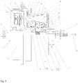
- Fig. 2 shows another specific example of this electric-bike hub motor means of the present invention, which is improved on the basis of the structure of Example 1, with the main improvements as follows:
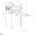
- Fig. 3 shows a third specific example of this electric-bike hub motor means of the present invention, which is improved on the basis of the structure of Example 1, with the main improvements as follows:
- this example also has the following structure:
- the clutch outer ring 10b extends at its right end out of the hub shell 2 and has a chain wheel 12, and a second unidirectional clutch 11 is provided between the rotor gear 5 and the spindle 1.
- This second unidirectional clutch 11 also has the conventional structure, which comprises an inner ring and an outer ring locked unidirectionally thereto, with the second unidirectional clutch secured at its inner ring to the spindle 1 and secured at its outer ring to the rotor gear 5, thus only allowing unidirectional rotation instead of bidirectional rotation of the rotor gear 5 around the spindle 1.
- the locking mechanism having the above function can have various structures well known in the mechanical field.
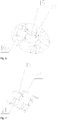
- the locking mechanism has the following structure: As shown in Figs. 3 , 6 and 7 , the locking mechanism comprises a sliding bush 14 sleeved axially slidably on the spindle 1, and a sliding positioning means that is used to drive the sliding bush 14 to slide axially on the spindle 1 and can position the sliding bush axially on the spindle, with the sliding bush 14 housed in the clutch outer ring 10b.
- the clutch outer ring 10b is provided in a position corresponding to each of the outer gear rings 10c with a radial through hole, where a leaf spring 22 locked on the clutch outer ring 10b is provided.
- the leaf spring 22 is provided outside with a roller 15 that is locked thereto, and is provided inside with a ball 21 that is located in the radial through hole and can be moved radially along the same; the outer gear ring 10c is provided with a fit groove corresponding to the roller 15 (not shown in the drawing).
- the sliding bush 14 is provided with a rim 14a that, when the sliding bush is slid axially on the spindle 1, can be moved outward along the radial through hole by abutting the ball 21 and then press the leaf spring 22 to deform it, such that the roller 15 secured on the leaf spring 22 is moved into the fit groove, thereby making the outer gear ring secured to the clutch outer ring 10b circumferentially.
- the sliding positioning means having the above function can have various structures well known in the mechanical field, such as an electromagnetic valve.
- the sliding positioning means has the following structure:
- the sliding positioning means comprises a setting bolt spring 17 sandwiched between the spindle 1 and the sliding bush 14, a central axle hole 18 provided on the spindle 1, a thimble 16 arranged in the central axle hole 18 and connected with the sliding bush 14, and a paddle (not shown in the drawing) that is fitted in contact with the thimble 16 and used for toggling the thimble to make it move axially in the central axle hole 18, with the paddle connected in transmission to a gear change hand lever (not shown in the drawing) on an electric-bike handlebar through a transmission line (not shown in the drawing).
- the ball 21 in any position of the clutch outer ring 10b is made to move outward radially (the cyclist can choose himself/herself by controlling the gear change hand lever), and then press the leaf spring 22 to deform it.
- the leaf spring 22 after being deformed, has a tendency to drive the roller 15 secured thereto to move outward; once the clutch outer ring 10b is rotated to a corresponding angular position, the roller 15, under the action of the deforming elastic force of the leaf spring 22, will partially enter the fit groove of the outer gear ring, with the rest part still in the clutch outer ring 10b, thus making the corresponding outer gear ring locked circumferentially to the clutch outer ring 10b.
- the cyclist can here also provide impetus through manpower to operate the motor, so as to help the motor provide additional torque for the hub shell 2 to rotate, which is achieved in the following way:
- the outer gear ring 10c can apply to the hub shell 2 the extra clockwise torque in addition to the motor rotor through the right planetary gear 9 engaging therewith.
- the outer gear ring 10c will apply clockwise rotational torque to the planetary carrier 6, and then drives the hub shell 2 to rotate clockwise, thus making the bike go forward. If the cyclist pedals the pedal at a constant rotational speed, since the respective outer gear rings 10c are different from each other in diameter, when the cyclist chooses to make the clutch outer ring 10b secured to different outer gear rings 10c circumferentially, the rotational speed of the hub shell 2 is then also different, thus achieving the multi-stage internal transmission function of this hub motor.
- a cyclist pursues the forward speed of the bike he/she can choose the gear position where the outer gear ring 10c with the biggest diameter (located at the rightmost and leftmost side in Fig. 2 ) is secured to the clutch outer ring 10b circumferentially; if the cyclist pursues the gradeability of the bike, he/she can choose the gear position where the outer gear ring 10c with the smallest diameter (located at the rightmost and leftmost side in Fig. 2 ) is secured to the clutch outer ring 10b circumferentially.
- the motor is not energized, the second clutch 11 between the rotor gear 4 and the spindle 1 is disengaged to allow free sliding.
- a secondary planetary gear 20 smaller than the respective right planetary gears 9 in diameter is also fixed on the planetary shaft 7, the secondary planetary gear 20 in Fig. 4 is located at the left side of all the right planetary gears 9, and a secondary outer gear ring 10d engaging with the secondary planetary gear 20 is also sleeved on the clutch outer ring10b at the right side of the left planetary gear 8, with the secondary outer gear ring 10d connected to the clutch outer ring 10b through a third unidirectional clutch 13.
- This third unidirectional clutch 13 also has the conventional structure, which comprises an inner ring and an outer ring locked unidirectionally thereto, the inner ring of the third unidirectional clutch being secured or connected to the clutch outer ring 10d as a whole, the outer ring of the third unidirectional clutch being secured or connected to the secondary outer gear ring 10d as a whole.
- this example also has the following structure: Between the sliding bush 14 and the spindle 1 is provided a supporting bearing (not shown in the drawing) having the existing conventional structure, which includes a bearing inner ring and a bearing outer ring that can be rotated relatively, the sliding bush 14 being secured to the bearing outer ring, the bearing inner ring being axially slidably sleeved on the spindle 1.
- the sliding bush 14 can also be axially slidably sleeved on the bearing outer ring, and the bearing inner ring can be secured on the spindle 1, which can also achieve the same effects as above.
- Fig. 4 shows a fourth specific example of this electric-bike hub motor means of the present invention, which is improved on the basis of the structure of Example 3, with the main improvements as follows:
- Fig. 5 shows a fifth specific example of this electric-bike hub motor means of the present invention, which is distinguished from Example 4 only in that the motor in this example is not provided with a chain wheel 12.
- Examples 1-5 described above the words “radial” and “axial”, in the absence of special note, are both based on the spindle 1 as the reference.
- the hub motor in Examples 1 and 4 is mostly used as a front-drive hub motor of the electric bike, while the hub motor in Examples 2, 3 and 5 is mostly used as a rear-drive hub motor of the electric bike.
- the planetary carrier 6 in Examples 1-5 above is integrated with the hub shell 2.
Landscapes
- Engineering & Computer Science (AREA)
- Chemical & Material Sciences (AREA)
- Combustion & Propulsion (AREA)
- Transportation (AREA)
- Mechanical Engineering (AREA)
- Power Engineering (AREA)
- Connection Of Motors, Electrical Generators, Mechanical Devices, And The Like (AREA)
Applications Claiming Priority (2)
| Application Number | Priority Date | Filing Date | Title |
|---|---|---|---|
| CN201410145608.3A CN103944305B (zh) | 2014-04-11 | 2014-04-11 | 电动自行车轮毂电机装置 |
| PCT/CN2014/088265 WO2015154400A1 (zh) | 2014-04-11 | 2014-10-10 | 电动自行车轮毂电机装置 |
Publications (2)
| Publication Number | Publication Date |
|---|---|
| EP3131184A1 true EP3131184A1 (de) | 2017-02-15 |
| EP3131184A4 EP3131184A4 (de) | 2018-01-03 |
Family
ID=51191841
Family Applications (1)
| Application Number | Title | Priority Date | Filing Date |
|---|---|---|---|
| EP14888625.2A Withdrawn EP3131184A4 (de) | 2014-04-11 | 2014-10-10 | Radnabenmotorvorrichtung für ein elektrofahrrad |
Country Status (3)
| Country | Link |
|---|---|
| EP (1) | EP3131184A4 (de) |
| CN (1) | CN103944305B (de) |
| WO (1) | WO2015154400A1 (de) |
Cited By (2)
| Publication number | Priority date | Publication date | Assignee | Title |
|---|---|---|---|---|
| NL2026760B1 (en) * | 2020-10-23 | 2022-06-17 | Advatech B V | Hybrid drive system for a bicycle |
| JPWO2024029381A1 (de) * | 2022-08-05 | 2024-02-08 |
Families Citing this family (12)
| Publication number | Priority date | Publication date | Assignee | Title |
|---|---|---|---|---|
| CN103944305B (zh) * | 2014-04-11 | 2016-04-13 | 苏州八方电机科技有限公司 | 电动自行车轮毂电机装置 |
| CN106741406B (zh) * | 2016-12-29 | 2022-10-04 | 浙江骑客机器人科技有限公司 | 一种体感纵向二轮车 |
| CN106602793B (zh) * | 2017-01-18 | 2023-05-30 | 深圳艾森驱动科技有限公司 | 一种带离合装置的轮毂发电机 |
| CN106995034B (zh) * | 2017-05-23 | 2022-10-18 | 爱克玛电器(苏州)有限公司 | 轮毂电机和配置该轮毂电机的电动自行车 |
| CN109120097A (zh) * | 2017-06-23 | 2019-01-01 | 西华大学 | 外转子直驱电机 |
| CN107685828B (zh) * | 2017-09-19 | 2023-03-24 | 八方电气(苏州)股份有限公司 | 电动自行车无级变速传动装置 |
| CN108973673A (zh) * | 2018-08-22 | 2018-12-11 | 倍能科技(广州)有限公司 | 直齿式车胎能量回收组件 |
| CN111327155B (zh) * | 2018-12-17 | 2024-07-19 | 宁波麦思动力系统有限公司 | 一种分轴式轮毂电机 |
| US12221190B2 (en) * | 2019-02-28 | 2025-02-11 | Amotech Co., Ltd. | Hub type driving device and electric bicycle using same |
| CN110040209A (zh) * | 2019-04-30 | 2019-07-23 | 德威(苏州)新能源有限公司 | 电动单车动力中置传动总成 |
| CN111525732B (zh) * | 2020-05-22 | 2024-05-31 | 苏州盛亿电机有限公司 | 通轴式轮毂电机 |
| CN113715952A (zh) * | 2021-08-23 | 2021-11-30 | 爱克玛电驱动系统(苏州)有限公司 | 电动自行车合力输出中轴电机 |
Family Cites Families (12)
| Publication number | Priority date | Publication date | Assignee | Title |
|---|---|---|---|---|
| JP2000134869A (ja) * | 1998-10-28 | 2000-05-12 | Nsk Ltd | 遊星歯車式変速機 |
| US6296072B1 (en) * | 1999-01-20 | 2001-10-02 | Opti-Bike Llc | Electric bicycle and methods |
| CN1808856B (zh) * | 2005-01-19 | 2012-02-22 | 毛风翔 | 电动轮毂 |
| US7357743B2 (en) * | 2005-06-17 | 2008-04-15 | Fengxiang Mao | Hub motor |
| CN2845291Y (zh) * | 2005-10-25 | 2006-12-06 | 宁波江北托普晟机电制造有限公司 | 无刷高速迷你电机 |
| CN201142618Y (zh) * | 2007-12-18 | 2008-10-29 | 朱明龙 | 一种轮毂的齿轮减速电机 |
| CN201393133Y (zh) * | 2009-04-17 | 2010-01-27 | 宁波北斗科技有限公司 | 一种用于电动车的减速电机 |
| CN201563027U (zh) * | 2009-12-10 | 2010-08-25 | 翁林华 | 电动自行车轮毂电机 |
| CN101856949A (zh) * | 2010-06-04 | 2010-10-13 | 苏州盛亿电机有限公司 | 电动轮毂 |
| CN102801245B (zh) * | 2012-09-05 | 2014-06-04 | 四川阿克拉斯电动车有限公司 | 电动车轮毂电机双离合器行星变挡机构 |
| CN203800745U (zh) * | 2014-04-11 | 2014-08-27 | 苏州八方电机科技有限公司 | 电动自行车轮毂电机装置 |
| CN103944305B (zh) * | 2014-04-11 | 2016-04-13 | 苏州八方电机科技有限公司 | 电动自行车轮毂电机装置 |
-
2014
- 2014-04-11 CN CN201410145608.3A patent/CN103944305B/zh active Active
- 2014-10-10 WO PCT/CN2014/088265 patent/WO2015154400A1/zh not_active Ceased
- 2014-10-10 EP EP14888625.2A patent/EP3131184A4/de not_active Withdrawn
Cited By (4)
| Publication number | Priority date | Publication date | Assignee | Title |
|---|---|---|---|---|
| NL2026760B1 (en) * | 2020-10-23 | 2022-06-17 | Advatech B V | Hybrid drive system for a bicycle |
| JPWO2024029381A1 (de) * | 2022-08-05 | 2024-02-08 | ||
| WO2024029381A1 (ja) * | 2022-08-05 | 2024-02-08 | ジヤトコ株式会社 | 自転車の電動アシストユニット及び電動アシスト自転車 |
| JP7842875B2 (ja) | 2022-08-05 | 2026-04-08 | ジヤトコ株式会社 | 自転車の電動アシストユニット及び電動アシスト自転車 |
Also Published As
| Publication number | Publication date |
|---|---|
| CN103944305B (zh) | 2016-04-13 |
| CN103944305A (zh) | 2014-07-23 |
| WO2015154400A1 (zh) | 2015-10-15 |
| EP3131184A4 (de) | 2018-01-03 |
Similar Documents
| Publication | Publication Date | Title |
|---|---|---|
| EP3131184A1 (de) | Radnabenmotorvorrichtung für ein elektrofahrrad | |
| EP3131185A1 (de) | Radnabenmotor für elektrofahrrad | |
| US20110177911A1 (en) | Planetary gear mechanism for a bicycle | |
| JP2016078618A (ja) | 自転車用アシストユニット | |
| WO2022105195A1 (zh) | 一种可多挡变速调节的中置电机 | |
| CN107399407B (zh) | 具有可选择固定齿轮的多速内齿轮毂 | |
| CN109311523B (zh) | 轮毂齿轮 | |
| JP2011168160A (ja) | 電動補助自転車 | |
| EP2724926A1 (de) | Zentraler Achsenenergie-Ausgabemechanismus | |
| CN100406343C (zh) | 电动自行车中置驱动同轴式动力组 | |
| TW201430237A (zh) | 自行車自動無段變速裝置 | |
| CN107131263B (zh) | 一种轴输入式三挡内变速器 | |
| EP3045756A1 (de) | Kupplungsvorrichtung | |
| CN203774952U (zh) | 电动自行车轮毂电机 | |
| KR101749896B1 (ko) | 가속감속 기어장치 | |
| JP2018534210A (ja) | 自転車のチェーンホイールキャリアとホイールハブとの間で用いる変速機、並びにその変速機を備えた後部アクスルおよび後部ホイール | |
| CN215883966U (zh) | 中置电机的牙盘变速装置及其中置电机 | |
| CN203800745U (zh) | 电动自行车轮毂电机装置 | |
| EP4048580B1 (de) | Antriebssystem für ein seitlich montiertes fahrradrad | |
| CN212861769U (zh) | 小轮径休闲车之传动机构 | |
| EP2900547B1 (de) | Pedalangetriebene vorrichtung mit motor | |
| JP2012040941A (ja) | 電動補助自転車 | |
| CN218641019U (zh) | 助力自行车中置电机变速离合一体化总成 | |
| CN213414146U (zh) | 一种直驱后置轮毂电机集成自动内变速花鼓结构 | |
| JP5567409B2 (ja) | 電動補助自転車 |
Legal Events
| Date | Code | Title | Description |
|---|---|---|---|
| STAA | Information on the status of an ep patent application or granted ep patent |
Free format text: STATUS: THE INTERNATIONAL PUBLICATION HAS BEEN MADE |
|
| PUAI | Public reference made under article 153(3) epc to a published international application that has entered the european phase |
Free format text: ORIGINAL CODE: 0009012 |
|
| STAA | Information on the status of an ep patent application or granted ep patent |
Free format text: STATUS: REQUEST FOR EXAMINATION WAS MADE |
|
| 17P | Request for examination filed |
Effective date: 20161101 |
|
| AK | Designated contracting states |
Kind code of ref document: A1 Designated state(s): AL AT BE BG CH CY CZ DE DK EE ES FI FR GB GR HR HU IE IS IT LI LT LU LV MC MK MT NL NO PL PT RO RS SE SI SK SM TR |
|
| AX | Request for extension of the european patent |
Extension state: BA ME |
|
| DAX | Request for extension of the european patent (deleted) | ||
| A4 | Supplementary search report drawn up and despatched |
Effective date: 20171204 |
|
| RIC1 | Information provided on ipc code assigned before grant |
Ipc: B62M 6/60 20100101ALI20171128BHEP Ipc: H02K 7/116 20060101ALI20171128BHEP Ipc: H02K 7/00 20060101AFI20171128BHEP Ipc: B62M 11/14 20060101ALI20171128BHEP |
|
| RAP1 | Party data changed (applicant data changed or rights of an application transferred) |
Owner name: BAFANG ELECTRIC (SUZHOU) CO., LTD. |
|
| GRAP | Despatch of communication of intention to grant a patent |
Free format text: ORIGINAL CODE: EPIDOSNIGR1 |
|
| STAA | Information on the status of an ep patent application or granted ep patent |
Free format text: STATUS: GRANT OF PATENT IS INTENDED |
|
| INTG | Intention to grant announced |
Effective date: 20181123 |
|
| RIN1 | Information on inventor provided before grant (corrected) |
Inventor name: DING, JUN Inventor name: HE, XIANBING Inventor name: WANG, HAIHUA Inventor name: ZHOU, QI Inventor name: XU, DAJUN |
|
| STAA | Information on the status of an ep patent application or granted ep patent |
Free format text: STATUS: THE APPLICATION IS DEEMED TO BE WITHDRAWN |
|
| 18D | Application deemed to be withdrawn |
Effective date: 20190404 |