EP3045756A1 - Kupplungsvorrichtung - Google Patents
Kupplungsvorrichtung Download PDFInfo
- Publication number
- EP3045756A1 EP3045756A1 EP14888995.9A EP14888995A EP3045756A1 EP 3045756 A1 EP3045756 A1 EP 3045756A1 EP 14888995 A EP14888995 A EP 14888995A EP 3045756 A1 EP3045756 A1 EP 3045756A1
- Authority
- EP
- European Patent Office
- Prior art keywords
- swivel
- spindle
- clutch
- sliding bush
- gear
- Prior art date
- Legal status (The legal status is an assumption and is not a legal conclusion. Google has not performed a legal analysis and makes no representation as to the accuracy of the status listed.)
- Withdrawn
Links
Images

Classifications
-
- F—MECHANICAL ENGINEERING; LIGHTING; HEATING; WEAPONS; BLASTING
- F16—ENGINEERING ELEMENTS AND UNITS; GENERAL MEASURES FOR PRODUCING AND MAINTAINING EFFECTIVE FUNCTIONING OF MACHINES OR INSTALLATIONS; THERMAL INSULATION IN GENERAL
- F16D—COUPLINGS FOR TRANSMITTING ROTATION; CLUTCHES; BRAKES
- F16D11/00—Clutches in which the members have interengaging parts
- F16D11/16—Clutches in which the members have interengaging parts with clutching members movable otherwise than only axially
-
- B—PERFORMING OPERATIONS; TRANSPORTING
- B62—LAND VEHICLES FOR TRAVELLING OTHERWISE THAN ON RAILS
- B62M—RIDER PROPULSION OF WHEELED VEHICLES OR SLEDGES; POWERED PROPULSION OF SLEDGES OR SINGLE-TRACK CYCLES; TRANSMISSIONS SPECIALLY ADAPTED FOR SUCH VEHICLES
- B62M11/00—Transmissions characterised by the use of interengaging toothed wheels or frictionally-engaging wheels
- B62M11/04—Transmissions characterised by the use of interengaging toothed wheels or frictionally-engaging wheels of changeable ratio
- B62M11/14—Transmissions characterised by the use of interengaging toothed wheels or frictionally-engaging wheels of changeable ratio with planetary gears
- B62M11/16—Transmissions characterised by the use of interengaging toothed wheels or frictionally-engaging wheels of changeable ratio with planetary gears built in, or adjacent to, the ground-wheel hub
-
- B—PERFORMING OPERATIONS; TRANSPORTING
- B62—LAND VEHICLES FOR TRAVELLING OTHERWISE THAN ON RAILS
- B62M—RIDER PROPULSION OF WHEELED VEHICLES OR SLEDGES; POWERED PROPULSION OF SLEDGES OR SINGLE-TRACK CYCLES; TRANSMISSIONS SPECIALLY ADAPTED FOR SUCH VEHICLES
- B62M6/00—Rider propulsion of wheeled vehicles with additional source of power, e.g. combustion engine or electric motor
- B62M6/40—Rider propelled cycles with auxiliary electric motor
- B62M6/60—Rider propelled cycles with auxiliary electric motor power-driven at axle parts
- B62M6/65—Rider propelled cycles with auxiliary electric motor power-driven at axle parts with axle and driving shaft arranged coaxially
-
- F—MECHANICAL ENGINEERING; LIGHTING; HEATING; WEAPONS; BLASTING
- F16—ENGINEERING ELEMENTS AND UNITS; GENERAL MEASURES FOR PRODUCING AND MAINTAINING EFFECTIVE FUNCTIONING OF MACHINES OR INSTALLATIONS; THERMAL INSULATION IN GENERAL
- F16D—COUPLINGS FOR TRANSMITTING ROTATION; CLUTCHES; BRAKES
- F16D21/00—Systems comprising a plurality of actuated clutches
- F16D21/02—Systems comprising a plurality of actuated clutches for interconnecting three or more shafts or other transmission members in different ways
- F16D21/04—Systems comprising a plurality of actuated clutches for interconnecting three or more shafts or other transmission members in different ways with a shaft carrying a number of rotatable transmission members, e.g. gears, each of which can be connected to the shaft by a clutching member or members between the shaft and the hub of the transmission member
-
- F—MECHANICAL ENGINEERING; LIGHTING; HEATING; WEAPONS; BLASTING
- F16—ENGINEERING ELEMENTS AND UNITS; GENERAL MEASURES FOR PRODUCING AND MAINTAINING EFFECTIVE FUNCTIONING OF MACHINES OR INSTALLATIONS; THERMAL INSULATION IN GENERAL
- F16D—COUPLINGS FOR TRANSMITTING ROTATION; CLUTCHES; BRAKES
- F16D2300/00—Special features for couplings or clutches
- F16D2300/24—Concentric actuation rods, e.g. actuation rods extending concentrically through a shaft
Definitions
- the present invention relates to a clutch, which is especially applicable to bikes and electric bikes.
- An existing common clutch such as a wedge-type unidirectional clutch is generally composed of a clutch inner ring and a clutch outer ring locked unidirectionally thereto, the clutch outer ring being provided with a clutch gear secured or integrated thereto.
- the clutch gear on the clutch outer ring needs to be engaged with an outer gear to transmit torque.
- a purpose of the present invention is to provide a new clutch device, so as to solve the above problems.
- the clutch device as described comprises a spindle that is rotatably fitted with a swivel through a bearing; the swivel is also provided with at least two swivel gears of different diameters that can rotate circumferentially around the swivel but cannot move axially, with a locking mechanism also provided between the swivel and the swivel gear that can secure them both together circumferentially.
- the locking mechanism includes a sliding bush that can be slidably sleeved axially on the spindle, and a sliding positioning device that is used to drive the sliding bush to slide axially on the spindle and can position the sliding bush axially on the spindle, with the sliding bush located in the swivel;
- the swivel is provided in a position corresponding to each of the swivel gears with a corresponding radial through hole, which is provided with a spring strip locked on the swivel;
- the spring strip is provided with a roller that is locked outside this spring strip, and is provided inside with a ball that is located in the radial through hole and can move radially along the radial through hole, with the swivel gear provided with a fit groove corresponding to the roller;
- the sliding bush is provided with a convex ring that, when the sliding bush slides axially on the spindle, can move outward along the radial through hole by abut
- the sliding positioning device includes a setting bolt spring sleeved on the spindle and sandwiched between the spindle and the sliding bush, a central axial hole provided on the spindle (1), a thimble arranged in the central axial hole and connected with the sliding bush, and a paddle that is fitted in contact with the thimble and used for poking the thimble to make it move axially in the central axial hole, with the paddle connected in transmission to a gear change hand lever through a shift cable.
- the sliding positioning device is an electromagnetic valve.
- a supporting bearing which has a relatively rotatable bearing inner ring and bearing outer ring, the sliding bush being secured to the bearing outer ring, the bearing inner ring being axially slidably sleeved on the spindle.
- a supporting bearing which has a relatively rotatable bearing inner ring and bearing outer ring, the sliding bush being axially slidably sleeved on the bearing outer ring, the bearing inner ring being secured on the spindle.
- a unidirectional clutch which has a clutch inner ring and a clutch outer ring locked unidirectionally thereto, the clutch outer ring being secured to the swivel, the clutch inner ring being secured to the spindle.
- this clutch device of the present invention having a plurality of clutch gears (swivel gears) of different diameters, adjusts the locking mechanism to select the desired swivel gear to secure to the swivel circumferentially according to the needs of users, so as to obtain the reduction ratio and output torque desired by the users.
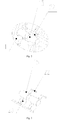
- Fig. 1 shows the structure of an electric-biker hub motor provided with this clutch device of the present invention.
- This electric-biker hub motor includes a horizontal spindle 1, which is provided with a hub shell 2 that can rotate around this spindle through a bearing (not labeled in Fig. 1 ), with the hub shell 2 composed of a shell body 2a and a shell end cover 2b secured to each other.
- the hub shell 2 is provided inside with a stator 3, a rotor 4 and a gear reduction mechanism, wherein the stator is secured on the spindle 1, with an outer-rotor inner-stator structure adopted in this example.
- a first major key improvement of this electric-biker hub motor of this example is that the gear reduction mechanism is totally different from a traditional one in structure, which is specifically as follows:
- the motor While in operation, the motor is powered on to make the rotor rotate clockwise in the right viewing direction shown in Fig. 1 , the rotor 4 drives the rotor gear 5 to rotate clockwise around the spindle 1, the rotor gear 5 then drives the left planetary gear 8 engaged therewith to rotate counterclockwise, the left planetary gear 8 then drives the planetary axle 7 and the right planetary gear 9 to rotate counterclockwise, the right planetary gear 9 then drives the sun gear 10 engaged therewith to rotate clockwise, and the sun gear 10 then drives the hub shell 2 secured thereto to rotate clockwise, thus making the electric-bike hub rotate clockwise forward.
- this gear reduction mechanism in this example can achieve multi-stage reduction of the rotor gear--the left planetary gear, the left planetary gear--the right planetary gear, and the right planetary gear--the sun gear, make this gear reduction mechanism have a very big reduction ratio, and greatly increase the torque outputted by the motor to the bike hub.
- the sun gear 10 is a unidirectional clutch having the existing conventional structure, which includes a clutch inner ring 10a and a clutch outer ring 10b locked unidirectionally thereto, wherein the clutch inner ring 10a is secured to the hub shell 2 (while the clutch outer ring 10b is not connected to the hub shell 2 directly), and a gear tooth 10c engaged with the right planetary gear 9 is formed on the clutch outer ring 10b. Only when the clutch outer ring 10b rotates clockwise in the right viewing direction shown in Fig. 1 , can it drive the clutch inner ring 10a to rotate clockwise therewith synchronously, while the clockwise rotation of the clutch inner ring 10a in the right viewing direction shown in Fig.
- this example also uses the following structure:
- the left planetary gear 8 is mounted on the planetary axle 7 through a planetary gear unidirectional clutch 21, which also uses the existing conventional structure that includes a planetary gear clutch inner ring (not labeled in Fig. 1 ) and a planetary gear clutch outer ring (not labeled in Fig. 1 ) locked unidirectionally thereto, wherein the planetary gear clutch inner ring is secured to the planetary axle 7, and the planetary gear clutch outer ring is secured to the left planetary gear 8. Only when the planetary gear clutch outer ring rotates counterclockwise in the right viewing direction shown in Fig.
- a second major key improvement of this electric-biker hub motor of this example is that this hub motor also has a multi-speed powering function and a multi-speed inner shift function, which are achieved in the following way:
- the locking mechanism having the above function can use various structures well known in the mechanical field.
- the locking mechanism uses the following structure: As shown in Figs. 1 to 3 , the locking mechanism includes a sliding bush 14 sleeved axially slidably on the spindle 1, and a sliding positioning device that is used to drive the sliding bush to slide axially on the spindle and can position the sliding bush axially on the spindle.
- the sliding bush 14 is located in the swivel 11, which is provided in a position corresponding to the clutch inner ring 10a and each of the swivel gears 13 with a corresponding radial through hole, where a spring strip 22 locked on the swivel 11 is provided; the spring strip 22 is provided with a roller 15 that is locked outside this spring strip, and is provided inside with a ball 23 that is located in the radial through hole and can move radially along the radial through hole.
- the swivel gear 13 and the clutch inner ring 10a are both provided with a fit groove corresponding to the roller 15.
- the sliding bush 14 is provided with a convex ring 14a that, when the sliding bush slides axially on the spindle 1, can move outward along the radial through hole by abutting the ball 23 and then press the spring strip 22 to deform, so that the roller 15 secured on the spring strip 22 moves into the fit groove, thereby making the swivel gear or the clutch inner ring secured to the swivel circumferentially.
- the sliding positioning device having the above function can use various structures well known in the mechanical field, such as an electromagnetic valve.
- the sliding positioning device uses the following structure:
- the sliding positioning device includes a setting bolt spring 17 sandwiched between the spindle 1 and the sliding bush 14, a central axial hole 18 provided on the spindle 1, a thimble 22 arranged in the central axial hole 18 and connected with the sliding bush 14, and a paddle (not shown in the figures) that is fitted in contact with the thimble and used for poking the thimble to make it move axially in the central axial hole 18, with the paddle connected in transmission to a gear change hand lever (not shown in the figures) on an electric bike handlebar through a shift cable (not shown in the figures).
- the rider can mobilize the gear change hand lever on the handlebar and drives the paddle to act through the shift cable, with the paddle then pushing the thimble 22 to move leftward in Fig. 1 along the central axial hole 18 of the spindle 1, thereby pushing the sliding bush 14 to move quantitatively along the spindle 1; alternatively, under the action of the elastic force of the setting bolt spring 17, the sliding bush 14 and the thimble 16 are pushed to move rightward in Fig. 1 along the central axial hole 18 of the spindle 1.
- the ball 23 in any position of the swivel 11 is made to move outward radially (the rider himself/herself can select by controlling the gear change hand lever), and then presses the spring strip 22 to deform.
- the spring strip 22 after deformation, has a tendency to drive the roller 15 secured thereto to move outward; once the swivel 11 rotates to a corresponding angular position, the roller 15, under the action of the deforming elastic force of the spring strip 22, will partially enter the fit groove with the rest part still in the swivel 11, thus making the corresponding clutch inner ring 10a or a certain swivel gear 13 locked circumferentially to the swivel 11.
- the swivel gear 13 can apply to the hub shell 2 the extra clockwise torsional moment in addition to the motor rotor through the power planetary gear 20 engaged therewith, while the clutch inner ring 10a applies directly to the hub shell 2 the extra clockwise torsional moment in addition to the motor rotor. It is thus clear that whether the rider selects through the gear change hand lever to make the swivel 11 secured circumferentially to the clutch inner ring 10a, or selects to make the swivel 11 secured circumferentially to a certain swivel gear 13, the rider can help the motor rotor 4 drive the hub shell 2 to rotate clockwise by providing artificial power to the motor.
- the rider pursues the forward speed of the bike, he/she can select a gear position where the clutch inner ring 10a is secured circumferentially to the swivel 11; if the rider pursues the gradeability of the bike, he/she can select a gear position where the swivel gear 13 having the smallest diameter is secured circumferentially to the swivel 11.
- the spindle 1, the swivel 11, the swivel gear 13 and the locking mechanism then compose the clutch device of the present invention, which has a plurality of clutch gears (i.e. swivel gears) of different diameters; in actual use, the user can adjust the locking mechanism to select the desired swivel gear to secure circumferentially to the swivel according to the needs of the user, so as to obtain the reduction ratio and output torque desired by the user.
- clutch gears i.e. swivel gears
- another unidirectional clutch can also be additionally added between the swivel 11 and the spindle 1, with the swivel 11 and the spindle 1 secured to the clutch outer ring and the clutch inner ring of the another unidirectional clutch, respectively.
- this example also uses the following structure: Between the sliding bush 14 and the spindle 1 is provided a supporting bearing (not shown in the figures), which has a relatively rotatable bearing inner ring and bearing outer ring (the conventional structure of bearings), the sliding bush 14 being secured to the bearing outer ring, the bearing inner ring being axially slidably sleeved on the spindle 1.
- the sliding bush 14 can also be axially slidably sleeved on the bearing outer ring, with the bearing inner ring secured on the spindle 1, which can also achieve the same effects as above.
- a supporting ball 19 is also mounted between the unidirectional clutch inner ring 10a and the swivel 11 in this example.
- the diameter of the right planetary gear 9 and the power planetary gear 20 is less than that of the left planetary gear 8.
Landscapes
- Engineering & Computer Science (AREA)
- Mechanical Engineering (AREA)
- General Engineering & Computer Science (AREA)
- Chemical & Material Sciences (AREA)
- Combustion & Propulsion (AREA)
- Transportation (AREA)
- Mechanical Operated Clutches (AREA)
Applications Claiming Priority (2)
| Application Number | Priority Date | Filing Date | Title |
|---|---|---|---|
| CN201410148970.6A CN104033510B (zh) | 2014-04-11 | 2014-04-11 | 离合器装置 |
| PCT/CN2014/088631 WO2015154407A1 (zh) | 2014-04-11 | 2014-10-15 | 离合器装置 |
Publications (2)
| Publication Number | Publication Date |
|---|---|
| EP3045756A1 true EP3045756A1 (de) | 2016-07-20 |
| EP3045756A4 EP3045756A4 (de) | 2017-03-08 |
Family
ID=51464429
Family Applications (1)
| Application Number | Title | Priority Date | Filing Date |
|---|---|---|---|
| EP14888995.9A Withdrawn EP3045756A4 (de) | 2014-04-11 | 2014-10-15 | Kupplungsvorrichtung |
Country Status (3)
| Country | Link |
|---|---|
| EP (1) | EP3045756A4 (de) |
| CN (1) | CN104033510B (de) |
| WO (1) | WO2015154407A1 (de) |
Families Citing this family (4)
| Publication number | Priority date | Publication date | Assignee | Title |
|---|---|---|---|---|
| CN104033510B (zh) * | 2014-04-11 | 2016-06-01 | 苏州八方电机科技有限公司 | 离合器装置 |
| CN108371797B (zh) * | 2018-04-28 | 2023-12-22 | 阎东 | 一种多模式滑行设备 |
| CN111038240B (zh) | 2019-12-11 | 2021-12-14 | 华为技术有限公司 | 动力总成、驱动系统和汽车 |
| CN114183477B (zh) * | 2021-12-13 | 2024-01-19 | 哈尔滨工业大学(威海) | 应用于摩擦增材制造装置的离合器 |
Family Cites Families (17)
| Publication number | Priority date | Publication date | Assignee | Title |
|---|---|---|---|---|
| GB191516015A (en) * | 1915-11-12 | 1916-03-09 | Thomas Charles Juckes | Improvements in Clutches for Motor Cycles and the like. |
| US1913949A (en) * | 1928-12-06 | 1933-06-13 | Adolphe C Peterson | Manually selective power actuated band gear change means |
| GB856625A (en) * | 1956-01-21 | 1960-12-21 | Getrag Getriebe Zahnrad | Improvements relating to change-speed gearing |
| US3354738A (en) * | 1965-06-09 | 1967-11-28 | Ford Motor Co | Multiple speed ratio power transmission mechanism |
| DE1680586B1 (de) * | 1967-02-09 | 1970-09-24 | Vni K I T I Motosiklov I Malol | Schaltgetriebe,vorzugsweise fuer Motorraeder,Motorroller und Mopedfahrzeuge |
| SU642542A1 (ru) * | 1976-12-01 | 1979-01-15 | Вильнюсский Станкостроительный Завод "Жальгирис" | Муфта включени |
| JPH0626762Y2 (ja) * | 1987-06-10 | 1994-07-20 | 株式会社神崎高級工機製作所 | 歩行型芝刈機の走行装置 |
| CN2379643Y (zh) * | 1999-08-11 | 2000-05-24 | 石油地球物理勘探局装备制造总厂 | 气动摩擦片式离合器 |
| FR2803251B1 (fr) * | 1999-12-30 | 2002-05-03 | Peugeot Citroen Automobiles Sa | Dispositif d'entrainement de l'arbre primaire d'une boite de vitesses pour vehicule a propulsion hybride |
| CN2459482Y (zh) * | 2001-01-20 | 2001-11-14 | 席星航 | 曲轴摩擦启动及自动卸载式超越离合器 |
| CN1808856B (zh) * | 2005-01-19 | 2012-02-22 | 毛风翔 | 电动轮毂 |
| CN2898426Y (zh) * | 2006-04-02 | 2007-05-09 | 娄底市三星矿山设备制造有限公司 | 齿轮离合器 |
| CN100513220C (zh) * | 2006-10-27 | 2009-07-15 | 西南大学 | 电动车自适应传动传感两档自动变速电动轮毂 |
| CN201080014Y (zh) * | 2007-08-06 | 2008-07-02 | 周富杭 | 刚性离合器压力机的快速离合制动装置 |
| CN102801245B (zh) * | 2012-09-05 | 2014-06-04 | 四川阿克拉斯电动车有限公司 | 电动车轮毂电机双离合器行星变挡机构 |
| CN104033510B (zh) * | 2014-04-11 | 2016-06-01 | 苏州八方电机科技有限公司 | 离合器装置 |
| CN203770472U (zh) * | 2014-04-11 | 2014-08-13 | 苏州八方电机科技有限公司 | 离合器装置 |
-
2014
- 2014-04-11 CN CN201410148970.6A patent/CN104033510B/zh active Active
- 2014-10-15 EP EP14888995.9A patent/EP3045756A4/de not_active Withdrawn
- 2014-10-15 WO PCT/CN2014/088631 patent/WO2015154407A1/zh not_active Ceased
Non-Patent Citations (1)
| Title |
|---|
| See references of WO2015154407A1 * |
Also Published As
| Publication number | Publication date |
|---|---|
| EP3045756A4 (de) | 2017-03-08 |
| WO2015154407A1 (zh) | 2015-10-15 |
| CN104033510B (zh) | 2016-06-01 |
| CN104033510A (zh) | 2014-09-10 |
Similar Documents
| Publication | Publication Date | Title |
|---|---|---|
| EP3131185A1 (de) | Radnabenmotor für elektrofahrrad | |
| EP3131184A1 (de) | Radnabenmotorvorrichtung für ein elektrofahrrad | |
| US8652000B2 (en) | Clutch type driving mechanism for hybrid powered vehicle | |
| TWI667153B (zh) | 自行車輪轂 | |
| JP6209508B2 (ja) | 自転車用ドライブユニット | |
| US20110177911A1 (en) | Planetary gear mechanism for a bicycle | |
| JP2016078618A (ja) | 自転車用アシストユニット | |
| ZA201100951B (en) | A forced speed changing apparatus of bicycle | |
| CN105090484A (zh) | 电动摩托车内转子电机螺旋式锥套传动自适应自动变速驱动总成 | |
| JP2009126513A (ja) | 自転車用内装変速機 | |
| EP2724926A1 (de) | Zentraler Achsenenergie-Ausgabemechanismus | |
| EP3045756A1 (de) | Kupplungsvorrichtung | |
| CN107131263B (zh) | 一种轴输入式三挡内变速器 | |
| CN203774952U (zh) | 电动自行车轮毂电机 | |
| CN101323252A (zh) | 锥盘离合凸轮自适应自动变速轮毂 | |
| JP2018534210A (ja) | 自転車のチェーンホイールキャリアとホイールハブとの間で用いる変速機、並びにその変速機を備えた後部アクスルおよび後部ホイール | |
| CN109606530B (zh) | 自行车变速机构和自行车 | |
| CN107244378B (zh) | 一种三挡内变速器 | |
| CN203800745U (zh) | 电动自行车轮毂电机装置 | |
| CN106005236B (zh) | 一种行星变速器内置式自行车变速传动机构 | |
| KR101932162B1 (ko) | 회전력을 증가시키기 위한 크랭크 조립체 | |
| CN205837121U (zh) | 一种行星变速器内置式自行车变速传动机构 | |
| KR101160632B1 (ko) | 자전거 변속기 | |
| CN206802215U (zh) | 一种轴输入式三挡内变速器 | |
| KR101644747B1 (ko) | 외발자전거 |
Legal Events
| Date | Code | Title | Description |
|---|---|---|---|
| PUAI | Public reference made under article 153(3) epc to a published international application that has entered the european phase |
Free format text: ORIGINAL CODE: 0009012 |
|
| 17P | Request for examination filed |
Effective date: 20160414 |
|
| AK | Designated contracting states |
Kind code of ref document: A1 Designated state(s): AL AT BE BG CH CY CZ DE DK EE ES FI FR GB GR HR HU IE IS IT LI LT LU LV MC MK MT NL NO PL PT RO RS SE SI SK SM TR |
|
| AX | Request for extension of the european patent |
Extension state: BA ME |
|
| A4 | Supplementary search report drawn up and despatched |
Effective date: 20170206 |
|
| RIC1 | Information provided on ipc code assigned before grant |
Ipc: F16D 21/04 20060101ALI20170131BHEP Ipc: B62M 11/16 20060101ALI20170131BHEP Ipc: F16D 21/08 20060101ALI20170131BHEP Ipc: F16D 11/16 20060101ALI20170131BHEP Ipc: B62M 6/65 20100101ALI20170131BHEP Ipc: F16D 41/24 20060101AFI20170131BHEP |
|
| DAX | Request for extension of the european patent (deleted) | ||
| RAP1 | Party data changed (applicant data changed or rights of an application transferred) |
Owner name: BAFANG ELECTRIC (SUZHOU) CO., LTD. |
|
| GRAP | Despatch of communication of intention to grant a patent |
Free format text: ORIGINAL CODE: EPIDOSNIGR1 |
|
| STAA | Information on the status of an ep patent application or granted ep patent |
Free format text: STATUS: GRANT OF PATENT IS INTENDED |
|
| INTG | Intention to grant announced |
Effective date: 20190903 |
|
| STAA | Information on the status of an ep patent application or granted ep patent |
Free format text: STATUS: THE APPLICATION IS DEEMED TO BE WITHDRAWN |
|
| 18D | Application deemed to be withdrawn |
Effective date: 20200114 |