EP3045756A1 - Clutch device - Google Patents
Clutch device Download PDFInfo
- Publication number
- EP3045756A1 EP3045756A1 EP14888995.9A EP14888995A EP3045756A1 EP 3045756 A1 EP3045756 A1 EP 3045756A1 EP 14888995 A EP14888995 A EP 14888995A EP 3045756 A1 EP3045756 A1 EP 3045756A1
- Authority
- EP
- European Patent Office
- Prior art keywords
- swivel
- spindle
- clutch
- sliding bush
- gear
- Prior art date
- Legal status (The legal status is an assumption and is not a legal conclusion. Google has not performed a legal analysis and makes no representation as to the accuracy of the status listed.)
- Withdrawn
Links
Images

Classifications
-
- F—MECHANICAL ENGINEERING; LIGHTING; HEATING; WEAPONS; BLASTING
- F16—ENGINEERING ELEMENTS AND UNITS; GENERAL MEASURES FOR PRODUCING AND MAINTAINING EFFECTIVE FUNCTIONING OF MACHINES OR INSTALLATIONS; THERMAL INSULATION IN GENERAL
- F16D—COUPLINGS FOR TRANSMITTING ROTATION; CLUTCHES; BRAKES
- F16D11/00—Clutches in which the members have interengaging parts
- F16D11/16—Clutches in which the members have interengaging parts with clutching members movable otherwise than only axially
-
- B—PERFORMING OPERATIONS; TRANSPORTING
- B62—LAND VEHICLES FOR TRAVELLING OTHERWISE THAN ON RAILS
- B62M—RIDER PROPULSION OF WHEELED VEHICLES OR SLEDGES; POWERED PROPULSION OF SLEDGES OR SINGLE-TRACK CYCLES; TRANSMISSIONS SPECIALLY ADAPTED FOR SUCH VEHICLES
- B62M11/00—Transmissions characterised by the use of interengaging toothed wheels or frictionally-engaging wheels
- B62M11/04—Transmissions characterised by the use of interengaging toothed wheels or frictionally-engaging wheels of changeable ratio
- B62M11/14—Transmissions characterised by the use of interengaging toothed wheels or frictionally-engaging wheels of changeable ratio with planetary gears
- B62M11/16—Transmissions characterised by the use of interengaging toothed wheels or frictionally-engaging wheels of changeable ratio with planetary gears built in, or adjacent to, the ground-wheel hub
-
- B—PERFORMING OPERATIONS; TRANSPORTING
- B62—LAND VEHICLES FOR TRAVELLING OTHERWISE THAN ON RAILS
- B62M—RIDER PROPULSION OF WHEELED VEHICLES OR SLEDGES; POWERED PROPULSION OF SLEDGES OR SINGLE-TRACK CYCLES; TRANSMISSIONS SPECIALLY ADAPTED FOR SUCH VEHICLES
- B62M6/00—Rider propulsion of wheeled vehicles with additional source of power, e.g. combustion engine or electric motor
- B62M6/40—Rider propelled cycles with auxiliary electric motor
- B62M6/60—Rider propelled cycles with auxiliary electric motor power-driven at axle parts
- B62M6/65—Rider propelled cycles with auxiliary electric motor power-driven at axle parts with axle and driving shaft arranged coaxially
-
- F—MECHANICAL ENGINEERING; LIGHTING; HEATING; WEAPONS; BLASTING
- F16—ENGINEERING ELEMENTS AND UNITS; GENERAL MEASURES FOR PRODUCING AND MAINTAINING EFFECTIVE FUNCTIONING OF MACHINES OR INSTALLATIONS; THERMAL INSULATION IN GENERAL
- F16D—COUPLINGS FOR TRANSMITTING ROTATION; CLUTCHES; BRAKES
- F16D21/00—Systems comprising a plurality of actuated clutches
- F16D21/02—Systems comprising a plurality of actuated clutches for interconnecting three or more shafts or other transmission members in different ways
- F16D21/04—Systems comprising a plurality of actuated clutches for interconnecting three or more shafts or other transmission members in different ways with a shaft carrying a number of rotatable transmission members, e.g. gears, each of which can be connected to the shaft by a clutching member or members between the shaft and the hub of the transmission member
-
- F—MECHANICAL ENGINEERING; LIGHTING; HEATING; WEAPONS; BLASTING
- F16—ENGINEERING ELEMENTS AND UNITS; GENERAL MEASURES FOR PRODUCING AND MAINTAINING EFFECTIVE FUNCTIONING OF MACHINES OR INSTALLATIONS; THERMAL INSULATION IN GENERAL
- F16D—COUPLINGS FOR TRANSMITTING ROTATION; CLUTCHES; BRAKES
- F16D2300/00—Special features for couplings or clutches
- F16D2300/24—Concentric actuation rods, e.g. actuation rods extending concentrically through a shaft
Definitions
- the present invention relates to a clutch, which is especially applicable to bikes and electric bikes.
- An existing common clutch such as a wedge-type unidirectional clutch is generally composed of a clutch inner ring and a clutch outer ring locked unidirectionally thereto, the clutch outer ring being provided with a clutch gear secured or integrated thereto.
- the clutch gear on the clutch outer ring needs to be engaged with an outer gear to transmit torque.
- a purpose of the present invention is to provide a new clutch device, so as to solve the above problems.
- the clutch device as described comprises a spindle that is rotatably fitted with a swivel through a bearing; the swivel is also provided with at least two swivel gears of different diameters that can rotate circumferentially around the swivel but cannot move axially, with a locking mechanism also provided between the swivel and the swivel gear that can secure them both together circumferentially.
- the locking mechanism includes a sliding bush that can be slidably sleeved axially on the spindle, and a sliding positioning device that is used to drive the sliding bush to slide axially on the spindle and can position the sliding bush axially on the spindle, with the sliding bush located in the swivel;
- the swivel is provided in a position corresponding to each of the swivel gears with a corresponding radial through hole, which is provided with a spring strip locked on the swivel;
- the spring strip is provided with a roller that is locked outside this spring strip, and is provided inside with a ball that is located in the radial through hole and can move radially along the radial through hole, with the swivel gear provided with a fit groove corresponding to the roller;
- the sliding bush is provided with a convex ring that, when the sliding bush slides axially on the spindle, can move outward along the radial through hole by abut
- the sliding positioning device includes a setting bolt spring sleeved on the spindle and sandwiched between the spindle and the sliding bush, a central axial hole provided on the spindle (1), a thimble arranged in the central axial hole and connected with the sliding bush, and a paddle that is fitted in contact with the thimble and used for poking the thimble to make it move axially in the central axial hole, with the paddle connected in transmission to a gear change hand lever through a shift cable.
- the sliding positioning device is an electromagnetic valve.
- a supporting bearing which has a relatively rotatable bearing inner ring and bearing outer ring, the sliding bush being secured to the bearing outer ring, the bearing inner ring being axially slidably sleeved on the spindle.
- a supporting bearing which has a relatively rotatable bearing inner ring and bearing outer ring, the sliding bush being axially slidably sleeved on the bearing outer ring, the bearing inner ring being secured on the spindle.
- a unidirectional clutch which has a clutch inner ring and a clutch outer ring locked unidirectionally thereto, the clutch outer ring being secured to the swivel, the clutch inner ring being secured to the spindle.
- this clutch device of the present invention having a plurality of clutch gears (swivel gears) of different diameters, adjusts the locking mechanism to select the desired swivel gear to secure to the swivel circumferentially according to the needs of users, so as to obtain the reduction ratio and output torque desired by the users.
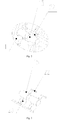
- Fig. 1 shows the structure of an electric-biker hub motor provided with this clutch device of the present invention.
- This electric-biker hub motor includes a horizontal spindle 1, which is provided with a hub shell 2 that can rotate around this spindle through a bearing (not labeled in Fig. 1 ), with the hub shell 2 composed of a shell body 2a and a shell end cover 2b secured to each other.
- the hub shell 2 is provided inside with a stator 3, a rotor 4 and a gear reduction mechanism, wherein the stator is secured on the spindle 1, with an outer-rotor inner-stator structure adopted in this example.
- a first major key improvement of this electric-biker hub motor of this example is that the gear reduction mechanism is totally different from a traditional one in structure, which is specifically as follows:
- the motor While in operation, the motor is powered on to make the rotor rotate clockwise in the right viewing direction shown in Fig. 1 , the rotor 4 drives the rotor gear 5 to rotate clockwise around the spindle 1, the rotor gear 5 then drives the left planetary gear 8 engaged therewith to rotate counterclockwise, the left planetary gear 8 then drives the planetary axle 7 and the right planetary gear 9 to rotate counterclockwise, the right planetary gear 9 then drives the sun gear 10 engaged therewith to rotate clockwise, and the sun gear 10 then drives the hub shell 2 secured thereto to rotate clockwise, thus making the electric-bike hub rotate clockwise forward.
- this gear reduction mechanism in this example can achieve multi-stage reduction of the rotor gear--the left planetary gear, the left planetary gear--the right planetary gear, and the right planetary gear--the sun gear, make this gear reduction mechanism have a very big reduction ratio, and greatly increase the torque outputted by the motor to the bike hub.
- the sun gear 10 is a unidirectional clutch having the existing conventional structure, which includes a clutch inner ring 10a and a clutch outer ring 10b locked unidirectionally thereto, wherein the clutch inner ring 10a is secured to the hub shell 2 (while the clutch outer ring 10b is not connected to the hub shell 2 directly), and a gear tooth 10c engaged with the right planetary gear 9 is formed on the clutch outer ring 10b. Only when the clutch outer ring 10b rotates clockwise in the right viewing direction shown in Fig. 1 , can it drive the clutch inner ring 10a to rotate clockwise therewith synchronously, while the clockwise rotation of the clutch inner ring 10a in the right viewing direction shown in Fig.
- this example also uses the following structure:
- the left planetary gear 8 is mounted on the planetary axle 7 through a planetary gear unidirectional clutch 21, which also uses the existing conventional structure that includes a planetary gear clutch inner ring (not labeled in Fig. 1 ) and a planetary gear clutch outer ring (not labeled in Fig. 1 ) locked unidirectionally thereto, wherein the planetary gear clutch inner ring is secured to the planetary axle 7, and the planetary gear clutch outer ring is secured to the left planetary gear 8. Only when the planetary gear clutch outer ring rotates counterclockwise in the right viewing direction shown in Fig.
- a second major key improvement of this electric-biker hub motor of this example is that this hub motor also has a multi-speed powering function and a multi-speed inner shift function, which are achieved in the following way:
- the locking mechanism having the above function can use various structures well known in the mechanical field.
- the locking mechanism uses the following structure: As shown in Figs. 1 to 3 , the locking mechanism includes a sliding bush 14 sleeved axially slidably on the spindle 1, and a sliding positioning device that is used to drive the sliding bush to slide axially on the spindle and can position the sliding bush axially on the spindle.
- the sliding bush 14 is located in the swivel 11, which is provided in a position corresponding to the clutch inner ring 10a and each of the swivel gears 13 with a corresponding radial through hole, where a spring strip 22 locked on the swivel 11 is provided; the spring strip 22 is provided with a roller 15 that is locked outside this spring strip, and is provided inside with a ball 23 that is located in the radial through hole and can move radially along the radial through hole.
- the swivel gear 13 and the clutch inner ring 10a are both provided with a fit groove corresponding to the roller 15.
- the sliding bush 14 is provided with a convex ring 14a that, when the sliding bush slides axially on the spindle 1, can move outward along the radial through hole by abutting the ball 23 and then press the spring strip 22 to deform, so that the roller 15 secured on the spring strip 22 moves into the fit groove, thereby making the swivel gear or the clutch inner ring secured to the swivel circumferentially.
- the sliding positioning device having the above function can use various structures well known in the mechanical field, such as an electromagnetic valve.
- the sliding positioning device uses the following structure:
- the sliding positioning device includes a setting bolt spring 17 sandwiched between the spindle 1 and the sliding bush 14, a central axial hole 18 provided on the spindle 1, a thimble 22 arranged in the central axial hole 18 and connected with the sliding bush 14, and a paddle (not shown in the figures) that is fitted in contact with the thimble and used for poking the thimble to make it move axially in the central axial hole 18, with the paddle connected in transmission to a gear change hand lever (not shown in the figures) on an electric bike handlebar through a shift cable (not shown in the figures).
- the rider can mobilize the gear change hand lever on the handlebar and drives the paddle to act through the shift cable, with the paddle then pushing the thimble 22 to move leftward in Fig. 1 along the central axial hole 18 of the spindle 1, thereby pushing the sliding bush 14 to move quantitatively along the spindle 1; alternatively, under the action of the elastic force of the setting bolt spring 17, the sliding bush 14 and the thimble 16 are pushed to move rightward in Fig. 1 along the central axial hole 18 of the spindle 1.
- the ball 23 in any position of the swivel 11 is made to move outward radially (the rider himself/herself can select by controlling the gear change hand lever), and then presses the spring strip 22 to deform.
- the spring strip 22 after deformation, has a tendency to drive the roller 15 secured thereto to move outward; once the swivel 11 rotates to a corresponding angular position, the roller 15, under the action of the deforming elastic force of the spring strip 22, will partially enter the fit groove with the rest part still in the swivel 11, thus making the corresponding clutch inner ring 10a or a certain swivel gear 13 locked circumferentially to the swivel 11.
- the swivel gear 13 can apply to the hub shell 2 the extra clockwise torsional moment in addition to the motor rotor through the power planetary gear 20 engaged therewith, while the clutch inner ring 10a applies directly to the hub shell 2 the extra clockwise torsional moment in addition to the motor rotor. It is thus clear that whether the rider selects through the gear change hand lever to make the swivel 11 secured circumferentially to the clutch inner ring 10a, or selects to make the swivel 11 secured circumferentially to a certain swivel gear 13, the rider can help the motor rotor 4 drive the hub shell 2 to rotate clockwise by providing artificial power to the motor.
- the rider pursues the forward speed of the bike, he/she can select a gear position where the clutch inner ring 10a is secured circumferentially to the swivel 11; if the rider pursues the gradeability of the bike, he/she can select a gear position where the swivel gear 13 having the smallest diameter is secured circumferentially to the swivel 11.
- the spindle 1, the swivel 11, the swivel gear 13 and the locking mechanism then compose the clutch device of the present invention, which has a plurality of clutch gears (i.e. swivel gears) of different diameters; in actual use, the user can adjust the locking mechanism to select the desired swivel gear to secure circumferentially to the swivel according to the needs of the user, so as to obtain the reduction ratio and output torque desired by the user.
- clutch gears i.e. swivel gears
- another unidirectional clutch can also be additionally added between the swivel 11 and the spindle 1, with the swivel 11 and the spindle 1 secured to the clutch outer ring and the clutch inner ring of the another unidirectional clutch, respectively.
- this example also uses the following structure: Between the sliding bush 14 and the spindle 1 is provided a supporting bearing (not shown in the figures), which has a relatively rotatable bearing inner ring and bearing outer ring (the conventional structure of bearings), the sliding bush 14 being secured to the bearing outer ring, the bearing inner ring being axially slidably sleeved on the spindle 1.
- the sliding bush 14 can also be axially slidably sleeved on the bearing outer ring, with the bearing inner ring secured on the spindle 1, which can also achieve the same effects as above.
- a supporting ball 19 is also mounted between the unidirectional clutch inner ring 10a and the swivel 11 in this example.
- the diameter of the right planetary gear 9 and the power planetary gear 20 is less than that of the left planetary gear 8.
Abstract
Description
- The present invention relates to a clutch, which is especially applicable to bikes and electric bikes.
- An existing common clutch such as a wedge-type unidirectional clutch is generally composed of a clutch inner ring and a clutch outer ring locked unidirectionally thereto, the clutch outer ring being provided with a clutch gear secured or integrated thereto. In actual use, the clutch gear on the clutch outer ring needs to be engaged with an outer gear to transmit torque.
- However, for the existing clutch, since there is only one clutch gear provided on its clutch outer ring, the reduction ratio between the clutch and the outer gear is constant, and the drive torque is not adjustable.
- A purpose of the present invention is to provide a new clutch device, so as to solve the above problems.
- A technical solution of the present invention is as follows: The clutch device as described comprises a spindle that is rotatably fitted with a swivel through a bearing; the swivel is also provided with at least two swivel gears of different diameters that can rotate circumferentially around the swivel but cannot move axially, with a locking mechanism also provided between the swivel and the swivel gear that can secure them both together circumferentially.
- The locking mechanism includes a sliding bush that can be slidably sleeved axially on the spindle, and a sliding positioning device that is used to drive the sliding bush to slide axially on the spindle and can position the sliding bush axially on the spindle, with the sliding bush located in the swivel; the swivel is provided in a position corresponding to each of the swivel gears with a corresponding radial through hole, which is provided with a spring strip locked on the swivel; the spring strip is provided with a roller that is locked outside this spring strip, and is provided inside with a ball that is located in the radial through hole and can move radially along the radial through hole, with the swivel gear provided with a fit groove corresponding to the roller; the sliding bush is provided with a convex ring that, when the sliding bush slides axially on the spindle, can move outward along the radial through hole by abutting the ball and then press the spring strip to deform, so that the roller secured on the spring strip moves into the fit groove, thereby making the swivel gear secured to the swivel circumferentially.
- The sliding positioning device includes a setting bolt spring sleeved on the spindle and sandwiched between the spindle and the sliding bush, a central axial hole provided on the spindle (1), a thimble arranged in the central axial hole and connected with the sliding bush, and a paddle that is fitted in contact with the thimble and used for poking the thimble to make it move axially in the central axial hole, with the paddle connected in transmission to a gear change hand lever through a shift cable.
- The sliding positioning device is an electromagnetic valve.
- Between the sliding bush and the spindle is provided a supporting bearing, which has a relatively rotatable bearing inner ring and bearing outer ring, the sliding bush being secured to the bearing outer ring, the bearing inner ring being axially slidably sleeved on the spindle.
- Between the sliding bush and the spindle is provided a supporting bearing, which has a relatively rotatable bearing inner ring and bearing outer ring, the sliding bush being axially slidably sleeved on the bearing outer ring, the bearing inner ring being secured on the spindle.
- There are totally two swivel gears.
- Between the swivel and the spindle is provided a unidirectional clutch, which has a clutch inner ring and a clutch outer ring locked unidirectionally thereto, the clutch outer ring being secured to the swivel, the clutch inner ring being secured to the spindle.
- The present invention has the following advantages: In actual use, this clutch device of the present invention, having a plurality of clutch gears (swivel gears) of different diameters, adjusts the locking mechanism to select the desired swivel gear to secure to the swivel circumferentially according to the needs of users, so as to obtain the reduction ratio and output torque desired by the users.
- The present invention will be further described below with reference to drawings and examples.
-
Fig. 1 is a structure schematic view (a partial sectional view) of the electric-bike hub motor of this clutch device of the present invention, i.e. a practical application view of this clutch device of the present invention; -
Fig. 2 is a partial structure schematic view of this clutch device of the present invention; and -
Fig. 3 is another partial structure schematic view of this clutch device of the present invention. - Wherein: 1. a spindle; 2. a hub shell; 2a. a shell body; 2b. a shell end cover; 3. a stator; 4. a rotor; 5. a rotor gear; 6. a planetary carrier; 7. a planetary axle; 8. a left planetary gear; 9. a right planetary gear; 10. a sun gear; 10a. a clutch inner ring; 10b.
- a clutch outer ring; 10c. a gear tooth; 11. a swivel; 12. a chain wheel; 13. a swivel gear; 14. a sliding bush; 14a. a boss; 15. a pin; 16. a thimble; 17. a setting bolt spring; 18. a central axial hole; 19. a ball; 20. a power planetary gear; and 21. a planetary gear unidirectional clutch.
-
Fig. 1 shows the structure of an electric-biker hub motor provided with this clutch device of the present invention. This electric-biker hub motor includes ahorizontal spindle 1, which is provided with a hub shell 2 that can rotate around this spindle through a bearing (not labeled inFig. 1 ), with the hub shell 2 composed of a shell body 2a and ashell end cover 2b secured to each other. The hub shell 2 is provided inside with astator 3, a rotor 4 and a gear reduction mechanism, wherein the stator is secured on thespindle 1, with an outer-rotor inner-stator structure adopted in this example. - A first major key improvement of this electric-biker hub motor of this example is that the gear reduction mechanism is totally different from a traditional one in structure, which is specifically as follows:
- The gear reduction mechanism in this example is mainly composed of a
rotor gear 5, aplanetary carrier 6, a planetary axle 7, a left planetary gear 8, a rightplanetary gear 9 and asun gear 10. Wherein therotor gear 5 is rotatably coaxially sleeved on thespindle 1 and is secured to the rotor 4, with a bearing (not labeled inFig. 1 ) provided between therotor gear 5 and thespindle 1 for supporting. Theplanetary carrier 6 is secured on thespindle 1, and the planetary axle 7, disposed in parallel with thespindle 1, rotatably goes through theplanetary carrier 6 through a bearing (not labeled inFig. 1 ). There may be one or more planetary axles 7, with three planetary axles (only one can be seen inFig. 1 ) in this example. With the number of the left planetary gear 8 and the rightplanetary gear 9 equal to that of the planetary axle 7, in order to increase the reduction ratio and the output torque, the diameter of the left planetary gear 8 is generally greater than that of the rightplanetary gear 9, and the left planetary gear 8 and the rightplanetary gear 9 are both secured (including being integrally secured) on the planetary axle 7. Thesun gear 10 is rotatably coaxially sleeved on thespindle 1 and is secured to the hub shell 2. The left planetary gear 8 is engaged with therotor gear 5, and the rightplanetary gear 9 is engaged with thesun gear 10. - While in operation, the motor is powered on to make the rotor rotate clockwise in the right viewing direction shown in
Fig. 1 , the rotor 4 drives therotor gear 5 to rotate clockwise around thespindle 1, therotor gear 5 then drives the left planetary gear 8 engaged therewith to rotate counterclockwise, the left planetary gear 8 then drives the planetary axle 7 and the rightplanetary gear 9 to rotate counterclockwise, the rightplanetary gear 9 then drives thesun gear 10 engaged therewith to rotate clockwise, and thesun gear 10 then drives the hub shell 2 secured thereto to rotate clockwise, thus making the electric-bike hub rotate clockwise forward. - It is easy to see that, this gear reduction mechanism in this example can achieve multi-stage reduction of the rotor gear--the left planetary gear, the left planetary gear--the right planetary gear, and the right planetary gear--the sun gear, make this gear reduction mechanism have a very big reduction ratio, and greatly increase the torque outputted by the motor to the bike hub.
- In this example, the
sun gear 10 is a unidirectional clutch having the existing conventional structure, which includes a clutchinner ring 10a and a clutchouter ring 10b locked unidirectionally thereto, wherein the clutchinner ring 10a is secured to the hub shell 2 (while the clutchouter ring 10b is not connected to the hub shell 2 directly), and agear tooth 10c engaged with the rightplanetary gear 9 is formed on the clutchouter ring 10b. Only when the clutchouter ring 10b rotates clockwise in the right viewing direction shown inFig. 1 , can it drive the clutchinner ring 10a to rotate clockwise therewith synchronously, while the clockwise rotation of the clutchinner ring 10a in the right viewing direction shown inFig. 1 will not drive the clutchouter ring 10b to rotate. There is the following advantage for thesun gear 10 to use this structure: When the electric bike skids forward (here the hub shell 2 rotates clockwise in the right viewing direction shown inFig. 1 ), the hub shell 2 will not drive the rotor 4 to rotate, which reduces the skidding resistance of the bike. - In order to further reduce the skidding resistance of the electric bike, this example also uses the following structure: The left planetary gear 8 is mounted on the planetary axle 7 through a planetary gear
unidirectional clutch 21, which also uses the existing conventional structure that includes a planetary gear clutch inner ring (not labeled inFig. 1 ) and a planetary gear clutch outer ring (not labeled inFig. 1 ) locked unidirectionally thereto, wherein the planetary gear clutch inner ring is secured to the planetary axle 7, and the planetary gear clutch outer ring is secured to the left planetary gear 8. Only when the planetary gear clutch outer ring rotates counterclockwise in the right viewing direction shown inFig. 1 , can it drive the planetary gear clutch inner ring to rotate counterclockwise therewith synchronously, while the counterclockwise rotation of the planetary gear clutch inner ring in the right viewing direction shown inFig. 1 will not drive the planetary gear clutch outer ring to rotate. - A second major key improvement of this electric-biker hub motor of this example is that this hub motor also has a multi-speed powering function and a multi-speed inner shift function, which are achieved in the following way:
- The
spindle 1 is rotatably fitted through a bearing (not labeled inFig. 1 ) with aswivel 11 between the clutchinner ring 10a and thespindle 1; thisswivel 11, whose right end extends out of the hub shell 2 and has a chain wheel 12, is also provided with two swivel gears 13 of different diameters that can rotate circumferentially around the swivel but cannot move axially, with a locking mechanism also provided between theswivel 11 and theswivel gear 13 that can secure them both together circumferentially; and a powerplanetary gear 20 engaged with theswivel gear 13 is also secured on the planetary axle 7. It should be noted that, the number of theswivel gear 13 is not limited to two, but can also be one, three, four.... - The locking mechanism having the above function can use various structures well known in the mechanical field. In this example, the locking mechanism uses the following structure: As shown in
Figs. 1 to 3 , the locking mechanism includes a sliding bush 14 sleeved axially slidably on thespindle 1, and a sliding positioning device that is used to drive the sliding bush to slide axially on the spindle and can position the sliding bush axially on the spindle. The sliding bush 14 is located in theswivel 11, which is provided in a position corresponding to the clutchinner ring 10a and each of the swivel gears 13 with a corresponding radial through hole, where aspring strip 22 locked on theswivel 11 is provided; thespring strip 22 is provided with aroller 15 that is locked outside this spring strip, and is provided inside with aball 23 that is located in the radial through hole and can move radially along the radial through hole. Theswivel gear 13 and the clutchinner ring 10a are both provided with a fit groove corresponding to theroller 15. The sliding bush 14 is provided with aconvex ring 14a that, when the sliding bush slides axially on thespindle 1, can move outward along the radial through hole by abutting theball 23 and then press thespring strip 22 to deform, so that theroller 15 secured on thespring strip 22 moves into the fit groove, thereby making the swivel gear or the clutch inner ring secured to the swivel circumferentially. - The sliding positioning device having the above function can use various structures well known in the mechanical field, such as an electromagnetic valve. In this example, the sliding positioning device uses the following structure: The sliding positioning device includes a
setting bolt spring 17 sandwiched between thespindle 1 and the sliding bush 14, a centralaxial hole 18 provided on thespindle 1, athimble 22 arranged in the centralaxial hole 18 and connected with the sliding bush 14, and a paddle (not shown in the figures) that is fitted in contact with the thimble and used for poking the thimble to make it move axially in the centralaxial hole 18, with the paddle connected in transmission to a gear change hand lever (not shown in the figures) on an electric bike handlebar through a shift cable (not shown in the figures). - When the motor is powered on to drive the hub to rotate clockwise to drive the bike to run forward, the rider can mobilize the gear change hand lever on the handlebar and drives the paddle to act through the shift cable, with the paddle then pushing the
thimble 22 to move leftward inFig. 1 along the centralaxial hole 18 of thespindle 1, thereby pushing the sliding bush 14 to move quantitatively along thespindle 1; alternatively, under the action of the elastic force of thesetting bolt spring 17, the sliding bush 14 and thethimble 16 are pushed to move rightward inFig. 1 along the centralaxial hole 18 of thespindle 1. With the quantitative movement of the sliding bush 14 and theconvex ring 14a thereon in a plurality of positions, theball 23 in any position of theswivel 11 is made to move outward radially (the rider himself/herself can select by controlling the gear change hand lever), and then presses thespring strip 22 to deform. Thespring strip 22, after deformation, has a tendency to drive theroller 15 secured thereto to move outward; once theswivel 11 rotates to a corresponding angular position, theroller 15, under the action of the deforming elastic force of thespring strip 22, will partially enter the fit groove with the rest part still in theswivel 11, thus making the corresponding clutchinner ring 10a or acertain swivel gear 13 locked circumferentially to theswivel 11. Certainly, we can also specially set the groove type of the fit groove, so as to allow the outer tooth ring to be locked only unidirectionally to the clutchouter ring 10b, with its structure and principle similar to the wedge-type unidirectional clutch and no longer described here in detail. While thoseballs 23 without contact with theconvex ring 14a remain in place and will not move outward, and the correspondingroller 15 will then not extend into the fit groove, thus not having the circumferential locking function. At this point the rider pedals a bike pedal to drive the chain wheel 12 to rotate clockwise in the right viewing direction shown inFig. 1 , and then the chain wheel drives theswivel 11 as well as theswivel gear 13 or clutchinner ring 10a locked circumferentially to thisswivel 11 to rotate clockwise. Wherein theswivel gear 13 can apply to the hub shell 2 the extra clockwise torsional moment in addition to the motor rotor through the powerplanetary gear 20 engaged therewith, while the clutchinner ring 10a applies directly to the hub shell 2 the extra clockwise torsional moment in addition to the motor rotor. It is thus clear that whether the rider selects through the gear change hand lever to make theswivel 11 secured circumferentially to the clutchinner ring 10a, or selects to make theswivel 11 secured circumferentially to acertain swivel gear 13, the rider can help the motor rotor 4 drive the hub shell 2 to rotate clockwise by providing artificial power to the motor. Because the respective swivel gears 13 have different diameters, when the rider selects to make theswivel 11 secured circumferentially to the clutchinner ring 10a or the different swivel gears 13, the amount of the artificial power provided by the rider to this hub motor is then also different, thus achieving the multi-speed powering function of this hub motor. - When this hub motor is powered off to leave the bike in a power-off riding mode, for the same reason, the rider can also mobilize the gear change hand lever on the handlebar, so as to make the clutch
inner ring 10a or one of the swivel gears 13 locked circumferentially to theswivel 11. At this point the rider pedals a bike pedal to drive the chain wheel 12 to rotate clockwise in the right viewing direction shown inFig. 1 , and then the chain wheel drives theswivel 11 as well as theswivel gear 13 or clutchinner ring 10a secured circumferentially to thisswivel 11 to rotate clockwise, and then drives the hub shell 2 to rotate clockwise, thus making the bike run forward. It is thus clear that the rider, whether selecting through the gear change hand lever to make theswivel 11 secured circumferentially to the clutchinner ring 10a, or selecting to make theswivel 11 secured circumferentially to acertain swivel gear 13, can drive the hub shell 2 to go clockwise forward. If the rider pedals the pedal at a constant rotational speed, because the respective swivel gears 13 differ from one another in diameter, when the rider selects to make theswivel 11 secured circumferentially to the clutchinner ring 10a or the different swivel gears 13, the rotational speed of the hub shell 2 is then also different, thus achieving the multi-speed inner shift function of this hub motor. Generally, if the rider pursues the forward speed of the bike, he/she can select a gear position where the clutchinner ring 10a is secured circumferentially to theswivel 11; if the rider pursues the gradeability of the bike, he/she can select a gear position where theswivel gear 13 having the smallest diameter is secured circumferentially to theswivel 11. - It is thus clear that the
spindle 1, theswivel 11, theswivel gear 13 and the locking mechanism then compose the clutch device of the present invention, which has a plurality of clutch gears (i.e. swivel gears) of different diameters; in actual use, the user can adjust the locking mechanism to select the desired swivel gear to secure circumferentially to the swivel according to the needs of the user, so as to obtain the reduction ratio and output torque desired by the user. If theswivel 11 is desired to be able to rotate only unidirectionally around the spindle 1 (clockwise or counterclockwise) rather than bi-directionally, another unidirectional clutch can also be additionally added between theswivel 11 and thespindle 1, with theswivel 11 and thespindle 1 secured to the clutch outer ring and the clutch inner ring of the another unidirectional clutch, respectively. - In order to prevent high-speed sliding friction between the
pin 15 and the sliding bush 14 produced due to their direct contact and relative movement during the rotational movement of theswivel 11 and thepin 15 thereon, this example also uses the following structure: Between the sliding bush 14 and thespindle 1 is provided a supporting bearing (not shown in the figures), which has a relatively rotatable bearing inner ring and bearing outer ring (the conventional structure of bearings), the sliding bush 14 being secured to the bearing outer ring, the bearing inner ring being axially slidably sleeved on thespindle 1. Certainly, the sliding bush 14 can also be axially slidably sleeved on the bearing outer ring, with the bearing inner ring secured on thespindle 1, which can also achieve the same effects as above. - In order to ensure the connection strength between the
sun gear 10 and the hub shell 2 so as to prevent deformation of the unidirectional clutchinner ring 10a, a supportingball 19 is also mounted between the unidirectional clutchinner ring 10a and theswivel 11 in this example. - In this example, the diameter of the right
planetary gear 9 and the powerplanetary gear 20 is less than that of the left planetary gear 8. - "Radial" and "axially" in this example are mentioned with respect to the
spindle 1. Certainly, the above example is used only for explaining the technical concept and characteristics of the present invention. It is provided to make people understand the present invention and implement the same, rather than limit the scope of protection of the present invention. Any equivalent alteration or modification made according to the spiritual essence of the primary technical solution of the present invention should fall within the scope of protection of the present invention.
Claims (8)
- A clutch device, characterized in that: it comprises a spindle (1) that is rotatably fitted with a swivel (11) through a bearing; the swivel (11) is also provided with at least two swivel gears (13) of different diameters that can rotate circumferentially around the swivel but cannot move axially, with a locking mechanism also provided between the swivel (11) and the swivel gear (13) that can secure them both together circumferentially.
- The clutch device according to claim 1, characterized in that: the locking mechanism includes a sliding bush (14) that can be slidably sleeved axially on the spindle (1), and a sliding positioning device that is used to drive the sliding bush to slide axially on the spindle and can position the sliding bush axially on the spindle, with the sliding bush (14) located in the swivel (11); the swivel (11) is provided in a position corresponding to each of the swivel gears with a corresponding radial through hole, which is provided with a spring strip (22) locked on the swivel (11); the spring strip (22) is provided with a roller (15) that is locked outside this spring strip, and is provided inside with a ball (23) that is located in the radial through hole and can move radially along the radial through hole, with the swivel gear (13) provided with a fit groove corresponding to the roller (15); the sliding bush (14) is provided with a convex ring (14a) that, when the sliding bush slides axially on the spindle (1), can move outward along the radial through hole by abutting the ball (23) and then press the spring strip (22) to deform, so that the roller (15) secured on the spring strip (22) moves into the fit groove, thereby making the swivel gear (13) secured to the swivel (11) circumferentially.
- The clutch device according to claim 2, characterized in that: the sliding positioning device includes a setting bolt spring (17) sleeved on the spindle (1) and sandwiched between the spindle (1) and the sliding bush (14), a central axial hole (18) provided on the spindle (1), a thimble arranged in the central axial hole (18) and connected to the sliding bush (14), and a paddle that is fitted in contact with the thimble and used for poking the thimble to make it move axially in the central axial hole (18), with the paddle connected in transmission to a gear change hand lever through a shift cable.
- The clutch device according to claim 2, characterized in that: the sliding positioning device is an electromagnetic valve.
- The clutch device according to claim 2, 3 or 4, characterized in that: between the sliding bush (14) and the spindle (1) is provided a supporting bearing, which has a relatively rotatable bearing inner ring and bearing outer ring, the sliding bush (14) being secured to the bearing outer ring, the bearing inner ring being axially slidably sleeved on the spindle (1).
- The clutch device according to claim 2, 3 or 4, characterized in that: between the sliding bush (14) and the spindle is provided a supporting bearing, which has a relatively rotatable bearing inner ring and bearing outer ring, the sliding bush (14) being axially slidably sleeved on the bearing outer ring, the bearing inner ring being secured on the spindle (1).
- The clutch device according to claim 1, 2, 3 or 4, characterized in that: there are totally two swivel gears (13).
- The clutch device according to claim 1, 2, 3 or 4, characterized in that: between the swivel (11) and the spindle (1) is provided a unidirectional clutch, which has a clutch inner ring and a clutch outer ring locked unidirectionally thereto, the clutch outer ring being secured to the swivel (11), the clutch inner ring being secured to the spindle (1).
Applications Claiming Priority (2)
| Application Number | Priority Date | Filing Date | Title |
|---|---|---|---|
| CN201410148970.6A CN104033510B (en) | 2014-04-11 | 2014-04-11 | Clutch apparatus |
| PCT/CN2014/088631 WO2015154407A1 (en) | 2014-04-11 | 2014-10-15 | Clutch device |
Publications (2)
| Publication Number | Publication Date |
|---|---|
| EP3045756A1 true EP3045756A1 (en) | 2016-07-20 |
| EP3045756A4 EP3045756A4 (en) | 2017-03-08 |
Family
ID=51464429
Family Applications (1)
| Application Number | Title | Priority Date | Filing Date |
|---|---|---|---|
| EP14888995.9A Withdrawn EP3045756A4 (en) | 2014-04-11 | 2014-10-15 | Clutch device |
Country Status (3)
| Country | Link |
|---|---|
| EP (1) | EP3045756A4 (en) |
| CN (1) | CN104033510B (en) |
| WO (1) | WO2015154407A1 (en) |
Families Citing this family (4)
| Publication number | Priority date | Publication date | Assignee | Title |
|---|---|---|---|---|
| CN104033510B (en) * | 2014-04-11 | 2016-06-01 | 苏州八方电机科技有限公司 | Clutch apparatus |
| CN108371797B (en) * | 2018-04-28 | 2023-12-22 | 阎东 | Multi-mode sliding equipment |
| CN111038240B (en) * | 2019-12-11 | 2021-12-14 | 华为技术有限公司 | Power assembly, driving system and automobile |
| CN114183477B (en) * | 2021-12-13 | 2024-01-19 | 哈尔滨工业大学(威海) | Clutch applied to friction additive manufacturing device |
Family Cites Families (17)
| Publication number | Priority date | Publication date | Assignee | Title |
|---|---|---|---|---|
| GB191516015A (en) * | 1915-11-12 | 1916-03-09 | Thomas Charles Juckes | Improvements in Clutches for Motor Cycles and the like. |
| US1913949A (en) * | 1928-12-06 | 1933-06-13 | Adolphe C Peterson | Manually selective power actuated band gear change means |
| GB856625A (en) * | 1956-01-21 | 1960-12-21 | Getrag Getriebe Zahnrad | Improvements relating to change-speed gearing |
| US3354738A (en) * | 1965-06-09 | 1967-11-28 | Ford Motor Co | Multiple speed ratio power transmission mechanism |
| DE1680586B1 (en) * | 1967-02-09 | 1970-09-24 | Vni K I T I Motosiklov I Malol | Manual transmission, preferably for motorcycles, scooters and moped vehicles |
| SU642542A1 (en) * | 1976-12-01 | 1979-01-15 | Вильнюсский Станкостроительный Завод "Жальгирис" | Engagement clutch |
| JPH0626762Y2 (en) * | 1987-06-10 | 1994-07-20 | 株式会社神崎高級工機製作所 | Traveling device for walking lawn mower |
| CN2379643Y (en) * | 1999-08-11 | 2000-05-24 | 石油地球物理勘探局装备制造总厂 | Pneumatic friction wafer type clutch |
| FR2803251B1 (en) * | 1999-12-30 | 2002-05-03 | Peugeot Citroen Automobiles Sa | DEVICE FOR DRIVING THE PRIMARY SHAFT OF A GEARBOX FOR A HYBRID-DRIVEN VEHICLE |
| CN2459482Y (en) * | 2001-01-20 | 2001-11-14 | 席星航 | Crank shaft friction start and automatic unloading type coaster |
| CN1808856B (en) * | 2005-01-19 | 2012-02-22 | 毛风翔 | Electric wheel hub |
| CN2898426Y (en) * | 2006-04-02 | 2007-05-09 | 娄底市三星矿山设备制造有限公司 | Gear clutch |
| CN100513220C (en) * | 2006-10-27 | 2009-07-15 | 西南大学 | Electric vehicle self-adapting transmission sensing two-shift automatic variable speed electric wheel hub |
| CN201080014Y (en) * | 2007-08-06 | 2008-07-02 | 周富杭 | Fast on-off braking device for rigid clutch pressing machine |
| CN102801245B (en) * | 2012-09-05 | 2014-06-04 | 四川阿克拉斯电动车有限公司 | Electric vehicle hub motor double clutch planet gear-shifting mechanism |
| CN104033510B (en) * | 2014-04-11 | 2016-06-01 | 苏州八方电机科技有限公司 | Clutch apparatus |
| CN203770472U (en) * | 2014-04-11 | 2014-08-13 | 苏州八方电机科技有限公司 | Clutch device |
-
2014
- 2014-04-11 CN CN201410148970.6A patent/CN104033510B/en active Active
- 2014-10-15 WO PCT/CN2014/088631 patent/WO2015154407A1/en active Application Filing
- 2014-10-15 EP EP14888995.9A patent/EP3045756A4/en not_active Withdrawn
Non-Patent Citations (1)
| Title |
|---|
| See references of WO2015154407A1 * |
Also Published As
| Publication number | Publication date |
|---|---|
| EP3045756A4 (en) | 2017-03-08 |
| CN104033510A (en) | 2014-09-10 |
| WO2015154407A1 (en) | 2015-10-15 |
| CN104033510B (en) | 2016-06-01 |
Similar Documents
| Publication | Publication Date | Title |
|---|---|---|
| EP3131184A1 (en) | Electric bicycle wheel hub motor device | |
| EP3131185A1 (en) | Electric bicycle wheel hub motor | |
| US8652000B2 (en) | Clutch type driving mechanism for hybrid powered vehicle | |
| JP6259881B2 (en) | bicycle | |
| US20110177911A1 (en) | Planetary gear mechanism for a bicycle | |
| WO2016104564A1 (en) | Drive unit for bicycle | |
| JP4773499B2 (en) | Bicycle interior gearbox | |
| TW201808677A (en) | Bicycle hub | |
| EP3045756A1 (en) | Clutch device | |
| ZA201100951B (en) | A forced speed changing apparatus of bicycle | |
| JP2016078618A (en) | Bicycle assist unit | |
| EP2724926A1 (en) | Central axle power output mechanism | |
| KR100901436B1 (en) | Accelerator for bicycle for driving speed elevation | |
| JP5634842B2 (en) | Planetary gear mechanism and hub motor device for battery-assisted bicycle equipped with the same | |
| CN107131263B (en) | Shaft input type three-gear inner speed changer | |
| CN107244378B (en) | Three-gear internal transmission | |
| CN107719574A (en) | A kind of centre wheel inputs two shift transmissions | |
| US10604213B2 (en) | Bicycle transmission for use between a chain wheel carrier and a wheel hub of a bicycle, as well as rear axle and rear wheel provided with such a transmission | |
| CN203774952U (en) | Electric bicycle hub motor | |
| CN203800745U (en) | Electric bicycle wheel hub motor device | |
| KR101160632B1 (en) | The bicycle an transmission | |
| CN206802215U (en) | A kind of axle input type three keeps off internal speed changer | |
| CN107804162A (en) | Variable speed drive system | |
| KR101644747B1 (en) | Cycle with single wheel | |
| CN207565778U (en) | A kind of centre wheel inputs two shift transmissions |
Legal Events
| Date | Code | Title | Description |
|---|---|---|---|
| PUAI | Public reference made under article 153(3) epc to a published international application that has entered the european phase |
Free format text: ORIGINAL CODE: 0009012 |
|
| 17P | Request for examination filed |
Effective date: 20160414 |
|
| AK | Designated contracting states |
Kind code of ref document: A1 Designated state(s): AL AT BE BG CH CY CZ DE DK EE ES FI FR GB GR HR HU IE IS IT LI LT LU LV MC MK MT NL NO PL PT RO RS SE SI SK SM TR |
|
| AX | Request for extension of the european patent |
Extension state: BA ME |
|
| A4 | Supplementary search report drawn up and despatched |
Effective date: 20170206 |
|
| RIC1 | Information provided on ipc code assigned before grant |
Ipc: F16D 21/04 20060101ALI20170131BHEP Ipc: B62M 11/16 20060101ALI20170131BHEP Ipc: F16D 21/08 20060101ALI20170131BHEP Ipc: F16D 11/16 20060101ALI20170131BHEP Ipc: B62M 6/65 20100101ALI20170131BHEP Ipc: F16D 41/24 20060101AFI20170131BHEP |
|
| DAX | Request for extension of the european patent (deleted) | ||
| RAP1 | Party data changed (applicant data changed or rights of an application transferred) |
Owner name: BAFANG ELECTRIC (SUZHOU) CO., LTD. |
|
| GRAP | Despatch of communication of intention to grant a patent |
Free format text: ORIGINAL CODE: EPIDOSNIGR1 |
|
| INTG | Intention to grant announced |
Effective date: 20190903 |
|
| STAA | Information on the status of an ep patent application or granted ep patent |
Free format text: STATUS: THE APPLICATION IS DEEMED TO BE WITHDRAWN |
|
| 18D | Application deemed to be withdrawn |
Effective date: 20200114 |