EP3129763B1 - Universeller mechanischer tester zur messung der reibung und der verschleisseigenschaften von materialien - Google Patents
Universeller mechanischer tester zur messung der reibung und der verschleisseigenschaften von materialien Download PDFInfo
- Publication number
- EP3129763B1 EP3129763B1 EP15776104.0A EP15776104A EP3129763B1 EP 3129763 B1 EP3129763 B1 EP 3129763B1 EP 15776104 A EP15776104 A EP 15776104A EP 3129763 B1 EP3129763 B1 EP 3129763B1
- Authority
- EP
- European Patent Office
- Prior art keywords
- measuring
- stages
- further including
- specimen
- base
- Prior art date
- Legal status (The legal status is an assumption and is not a legal conclusion. Google has not performed a legal analysis and makes no representation as to the accuracy of the status listed.)
- Active
Links
Images


Classifications
-
- G—PHYSICS
- G01—MEASURING; TESTING
- G01N—INVESTIGATING OR ANALYSING MATERIALS BY DETERMINING THEIR CHEMICAL OR PHYSICAL PROPERTIES
- G01N3/00—Investigating strength properties of solid materials by application of mechanical stress
- G01N3/56—Investigating resistance to wear or abrasion
-
- G—PHYSICS
- G01—MEASURING; TESTING
- G01K—MEASURING TEMPERATURE; MEASURING QUANTITY OF HEAT; THERMALLY-SENSITIVE ELEMENTS NOT OTHERWISE PROVIDED FOR
- G01K13/00—Thermometers specially adapted for specific purposes
-
- G—PHYSICS
- G01—MEASURING; TESTING
- G01N—INVESTIGATING OR ANALYSING MATERIALS BY DETERMINING THEIR CHEMICAL OR PHYSICAL PROPERTIES
- G01N19/00—Investigating materials by mechanical methods
- G01N19/02—Measuring coefficient of friction between materials
-
- G—PHYSICS
- G01—MEASURING; TESTING
- G01N—INVESTIGATING OR ANALYSING MATERIALS BY DETERMINING THEIR CHEMICAL OR PHYSICAL PROPERTIES
- G01N29/00—Investigating or analysing materials by the use of ultrasonic, sonic or infrasonic waves; Visualisation of the interior of objects by transmitting ultrasonic or sonic waves through the object
- G01N29/04—Analysing solids
-
- G—PHYSICS
- G01—MEASURING; TESTING
- G01N—INVESTIGATING OR ANALYSING MATERIALS BY DETERMINING THEIR CHEMICAL OR PHYSICAL PROPERTIES
- G01N29/00—Investigating or analysing materials by the use of ultrasonic, sonic or infrasonic waves; Visualisation of the interior of objects by transmitting ultrasonic or sonic waves through the object
- G01N29/14—Investigating or analysing materials by the use of ultrasonic, sonic or infrasonic waves; Visualisation of the interior of objects by transmitting ultrasonic or sonic waves through the object using acoustic emission techniques
Definitions
- the invention relates in general to the field of tribology.
- the field of tribology involves the study of friction and wear on materials. Two or more objects are brought into contact with each other and a relative motion is started between the two contacting materials for the purpose of measuring the resulting friction forces. Over time a "wear" track may be created as result of damage caused by the two materials rubbing against each other; therefore, the wear on one or both of the objects can also be measured.
- the present invention describes a unique piece of equipment that allows the user to perform multiple tests with multiple configurations with a single mechanical tester and interchangeable, modular sample stages and accessories.
- the conventional equipment used for measuring friction and wear is dedicated to a particular test type and a corresponding test configuration. Examples include, without limitation, the configurations referred to in the art as block-on-ring, pin/ball/disk-on-disk, and reciprocating pin/ball on flat.
- the first represents a configuration where the sample stage includes a horizontal drive shaft rotating around its main axis. A ring specimen is coupled to the shaft for concurrent rotation and a test block is pushed radially against the edge of the ring with a known force. The friction force and/or the torque imparted on the shaft are measured, from which the coefficient of friction between the block and the specimen material can be calculated based on the known load (i.e., the normal force applied by the block).
- a disk specimen is mounted horizontally on a vertical rotating shaft in the sample stage.
- a ball or pin specimen is brought down from above into contact with the spinning face of the disk at a known radial distance from the axis of the shaft and a known normal force is applied.
- the frictional force between the ball or pin and the spinning disk and the resulting wear can be measured.
- a fixed disk, rather than a ball or pin is aligned axially with the spinning disk coupled to the stage and the two are brought into contact with a known force. In this configuration the friction and wear between the two disks can similarly be measured.
- the third exemplary type of test equipment is a reciprocating-type tester.
- an eccentric crank arm is used to transfer the rotary motion of a vertical drive shaft to a reciprocating motion in a horizontal plane of the stage where the sample is mounted.
- the horizontal reciprocating motion follows a sinusoidal velocity profile.
- a test specimen (a flat sample) is mounted on the reciprocating plane and again a ball or pin specimen is brought into contact with a known normal force. The resulting frictional force is measured and the coefficient can be calculated. Wear tests can be similarly carried out in conventional manner.
- U.S. Patent No. 6,418,776 describes a universal tester wherein alternative modules, each containing a motor and a dedicated drive, are available for use in different test configurations, such as described above.
- Each module includes a self-contained drive with a motor and is attached to a base plate in the frame of the unit. While this type of system requires less laboratory space and can be more economical than multiple dedicated testers, each replaceable stage unit still has its own motor, which is often the single most expensive component of the replaceable module. Also, because the motor is included in each modular stage, each module is necessarily larger than desirable in relation to the space available inside the base of the instrument and therefore only relatively small motors can be used.
- a universal tester of this type is also difficult for the user to configure and use properly with the software.
- the software In what has turned out to be a major problem and concern in the industry, the software must be set-up manually for each test configuration or there must be a dedicated piece of software for each test type, which can be cumbersome for the user and lead to serious mistakes when a test is not properly set up. The wrong choice of test parameters will produce misleading results; more importantly, however, it can also create dangerous situations due to unwarranted mechanical stresses that can result from erroneous test programming. If different test programs (referred to in the art as "scripts") are provided by the developer for each machine, they also require continuous technical support, which adds cost for the user as well as the supplier.
- This invention is directed at solving these problems with a mechanical tester capable of performing measurements in all above-described configurations with a single rotary drive.
- US 2009/320555A1 (Ebrecht etal ) describes a test device for the tribological examination of materials in which a test force is applied to examine the friction between materials.
- WO 2012/148101A2 (neoplus Co, Ltd et al) describes a three-module intergrated wear tester in which modular sample stages are all permanently mounted on the base of the test apparatus.
- the invention relates to a universal mechanical friction and wear test instrument having the features of claim 1.
- This allows the performance of multiple test protocols with a single machine.
- Such result is achieved by the use of modular sample stages that do not include a motor, each dedicated to a test configuration.
- the modules are manually coupled to the base of the instrument and are automatically recognized for activation of the correct software relevant to its configuration and test protocols (scripts).
- scripts the correct software relevant to its configuration and test protocols
- no extraneous protocol can be activated erroneously by an operator.
- a single motor housed in the frame of the instrument actuates the drive of each sample stage through a drivetrain and a coupling mechanism that is automatically engaged by the manual installation of the stage.
- Means for controlling and/or measuring the temperature and the humidity of the samples may be provided through a bank of dedicated expansion slots, such as peripheral component interconnect (PCI) slots, available for activation of respective software by inserting corresponding expansion cards. Additional slots and respective software are also available for voltage/resistance measurements and for acoustic-emission measurements on the materials under test. An electronic identification in each card ensures that only relevant software is enabled, thereby avoiding s erroneous script implementations.
- PCI peripheral component interconnect
- specimen and “sample” are used interchangeably to refer to the materials tested to determine their wear and friction characteristics.
- lower specimen or sample
- upper specimen or sample
- specimen is used to refer to the material coupled to the upper holder that is rigidly attached to the sensor unit in the carriage of the instrument to contact and exert a force against the lower specimen and to sense and measure the frictional reaction when a relative displacement is initiated or produced by the motion in the sample stage.
- the upper specimens may be a pin, a ball, a block or a disk acting on the lower specimen and the sample motion may be rotational over a horizontal axis, rotational over a vertical axis, or reciprocating linearly along a horizontal direction.
- the universal mechanical tester of the invention was developed to overcome the shortcomings of the instrument described in U.S. Patent No. 6,418,776 .
- the improvements lie in the configuration of the modules in relation to the base and frame of the instrument and in the mechanisms used to ensure the correct and safe coupling of the module for the desired test procedure. Accordingly, the tester of the invention is not described in detail herein other than as necessary to disclose the elements of the invention.
- the details of the conventional portions of the instrument can be found, for example, in the description of the instrument disclosed in U.S. Patent No. 6,418,776 .
- the tester is a machine capable of accepting modular sample stages that automatically activate only test protocols appropriate for the particular module installed in the instrument.
- a single motor is placed in the frame of the tester for driving all modular stages. Because the motor is housed in the frame, its size is not limited by space availability and it is provided so as to meet the largest power requirements intended for the instrument. In addition, the absence of a motor in the stages makes it possible to greatly reduce their size and correspondingly increase the space available for receiving test specimens in the instrument.
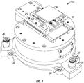
- Fig. 1 illustrates a tester 10 according to the invention.
- a transparent cover 12 encloses the test area for protection and environmental isolation of the specimens during testing, such as required for temperature and humidity control, for example.
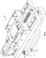
- Fig. 2 shows the tester 10 without the cover 12 to illustrate the relatively large test space allowed by a modular sample stage 14 modified according to the invention.
- Fig. 3 shows the tester with the sample stage 14 removed from it.
- the vertically translatable carriage 16, the horizontally translatable slide 18, the bidirectional force sensor assembly 20, and the various related actuating mechanisms are conventional and therefore not described in detail herein.
- the upper holder 22 (a chuck or equivalent device) for engaging the upper specimen (pin ball, block or disk, not shown) is similarly conventional, such as described in U.S. Patent No. 6,418,776 .
- the exemplary modular sample stage 14 is provided according to the invention for engagement within the base 24 of the tester 10.
- a single motor housed in the frame of the tester is used to actuate the motion of each sample stage (for reciprocation, vertical rotation, or horizontal rotation) though a drivetrain that includes a vertical shaft protruding upward with a coupling mechanism 26 from the center of the base 24 of the tester.
- Such coupling mechanism is preferably a bellows-type coupling to ensure the smooth engagement of the drive shaft 28 protruding from the underside of the stage 14, as seen in the bottom view of the stage in Fig. 5 .
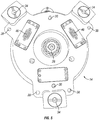
- the shaft 28 in the stage is adapted for automatic engagement of the coupling mechanism 26 when the stage is lowered over the base 24 of the tester.
- Guide pins 30 in the bottom of the stage module ( Fig. 5 ) and corresponding openings 32 in the base 24 of the instrument are provided to align the stage with the frame and secure it safely in place by means of a quick-connect locking mechanism, such as a ball lock 34 adapted to engage corresponding lock pins 36 protruding upward from the base 24.
- a quick-connect locking mechanism such as a ball lock 34 adapted to engage corresponding lock pins 36 protruding upward from the base 24.
- the stage 14 is also preferably bolted to the base 24 for additional security using dedicated openings 38,40 in the stage and base, respectively.
- the vertical shaft 28 for coupling the stage with the drivetrain shaft and motor in the base and frame of the tester is a feature common to all modular stages of the invention.
- the modular stage 14 is of the reciprocating motion kind. It includes a sample holder 42 for receiving a specimen 44 to be tested. The holder 42 is mounted on the stage 14 and is actuated by the shaft 28 to produce a linear reciprocating motion. The length of each stroke is measured as appropriate for a particular test protocol, such as by a Linear Variable Displacement Transducer (LVDT) connected to corresponding software that also controls the frequency of reciprocation.
- LVDT Linear Variable Displacement Transducer
- the LVDT device in the sample stage 14 is preferably connected to a microprocessor (not shown) housed in the frame of the tester by means of a blind-mate connector 46 provided for coupling from opposite sides of the stage and base, as seen in Figs. 5 and 6 , respectively.
- a microprocessor housed in the frame of the tester by means of a blind-mate connector 46 provided for coupling from opposite sides of the stage and base, as seen in Figs. 5 and 6 , respectively.
- the two components of the connector 46 are also engaged and communication between the LVTD and the microprocessor is automatically activated.
- each modular sample stage is also fitted with a means for its automatic identification, without any operator input. That is, each module contains an identifier that allows the system to immediately recognize the type of stage (reciprocating, rotating, etc.) and to activate only the software pertinent to the operation of that particular type of sample stage. For example, with a reciprocating stage the system would allow an operator to select the stroke length and the frequency of oscillation for a wear test script, or the pattern of tool motion in relation to the sample for a friction measurement, but it would not allow activation of any software corresponding to another sample stage (such as for tests requiring the vertical or horizontal rotation of the sample).
- the chips can be embedded in the blind-mate connector 46 that is automatically coupled when the stage is installed on the base 24 of the tester, as seen from Figs. 5 and 6 .
- such chips can be placed within the connector housing of a more traditional fashion device, such as a DB-9 style connector.
- An identifier could also consist of a mechanical device triggered by the coupling of the stage to the base of the tester, which in turn would activate the appropriate test protocol. This feature ensures not only that erroneous data are not collected, but, more importantly, also that no dangerous situation is generated by operator error in programming the tester for an incorrect test protocol.
- Fig. 7 shows in perspective view an alternative modular sample stage 50 dedicated to ball-on-disk, pin-on-disk or disk-on-disk tests.
- a disk 52 is mounted horizontally on a vertical rotating shaft (not seen) connected to the actuating shaft 28 in the sample stage.
- the underside of the stage 50 is identical to the one of stage 14 shown in Fig. 5 , with the same vertical drive shaft 28 for coupling the stage with the drivetrain shaft and motor in the base and frame of the tester.
- the same guide pins 30, ball locks 34 and openings 38 are provided to secure the stage within the tester.
- Blind-mate connectors 46 are similarly used for automatic identification of the stage and for providing appropriate electronic communication with the stage.
- Fig. 8 shows in perspective view another, alternative modular sample stage 60 dedicated to the block-on-ring configuration, where the sample stage includes a drive shaft 62 rotating a ring sample 64 along the shaft's horizontal axis and a block sample 66 forced against it by a support rod 68.
- Two force sensors 70 measure the forces acting between the two samples.
- the bottom side of the stage 60 is the same as described with reference to stages 14 and 50.
- Fig. 9 shows in perspective view yet another, alternative modular sample stage 80 dedicated to tests conducted when the lower specimen 82 is subjected to friction and/or scratch tests involving the continuous linear relative motion between upper and lower specimens.
- the same features described above for coupling the stage 80 to the base 24 of the tester 10 and for identifying the stage and controlling its operation are present in this module.
- the rotation of the vertical drive shaft 28 is used to produce in conventional manner the rotation of a horizontal worm screw 84 that in turn causes the sample holder 42 to move along a straight line.
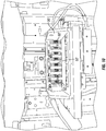
- the tester of the invention further provides sensors for measuring the temperature of the samples and the humidity in the environment containing the samples.
- a bank 90 of slots is provided in the tester for activating respective scripts in software by inserting expansion cards in respective dedicated slots 92 that enable test protocols relevant to temperature and/or humidity measurements, as applicable.
- Dedicated slots are also available for controlling and measuring voltage applied to the samples and for measuring resistance across the samples, as well as for acoustic-emission measurements on the materials under test.
- Each such card includes electronic circuitry configured to activate a relevant test protocol and is also labeled with an electronic identification that is automatically recognized by the system's software so as to enable only the scripts relevant to the particular card, thereby avoiding erroneous script implementations.
- the new instrument enables all types of test configurations with a single machine equipped with multiple sample-stage modules, each adapted for a particular type of test protocol.
- a single drive shaft is fitted with a mechanical quick connect coupler for transferring the torque carried by the drivetrain to each modular sample stage.
- One such coupler is a bellows coupling such as the MK, BK or BX series of couplings available from R+W® Company, but any coupler that allows for the quick connection of the drive to the drivetrain is suitable for the invention, one that requires no tools being preferred.
- the coupler have a bellows or other spring-like flexibility to accommodate misalignments between the shaft of the drivetrain and the drive shaft of the module.
- the modular stages be held in place by a hold-down mechanism that is tool-less, such as cams, ball-lock assemblies or quick clamps.
- any data obtained by calibration of instrument components be saved within the electronics of the component. This allows the component to be plugged into a new piece of equipment and be readily identified with its calibration parameters so the equipment can be used correctly without further calibration. It is also preferred that the data acquisition and motor control electronics be placed within the housing of the unit. This minimizes the electronic requirements of the computer mother board in terms of quantity of slots and slot type. This also minimizes the number of electronic connections between the computer and the test equipment.
- the test equipment can be designed to be connected with either USB 2.0, USB 3.0 or GigaE or other fast communication protocol.
- a processor programmed for identifying the module currently installed in the tester, for executing a corresponding predetermined set of test operations, and for controlling the various functions of the tester is preferably housed within the frame of the tester 10 but could also be a separate computer connected to the tester when needed.
- Embodiments of the present invention provide a universal apparatus for testing wear and friction characteristics of a material.
- Such apparatus includes a frame containing a carriage moveable along a vertical plane and a slide moveable along a horizontal plane, a force sensor assembly coupled to the slide, a holder for an upper specimen, the holder being coupled to the force sensor assembly, and a mechanism configured to cause the upper specimen to exert a predetermined force on a lower specimen.
- the apparatus also includes a plurality of modular sample stages, each of which stages includes a support for the lower specimen and a mechanism for producing a motion of the lower specimen relative to the upper specimen.
- the motion is rotational around a horizontal axis in one of the stages, rotational around a vertical axis in another of the stages, and linearly reciprocating along a horizontal direction in yet another of the stages.
- the apparatus additionally includes a base structured to support one of the plurality of modular sample stages, which base incorporates a locking mechanism adapted to couple the stage to the base and a rotational drive adapted for engagement of the mechanism for producing a motion of the lower specimen.
- the apparatus further includes a motor housed in the frame (which motor is adapted for actuation of the rotational drive), a controller having electronic circuitry programmed to vary the force exerted on the sample, and a processor programmed to execute a predetermined set of test operations.
- a universal apparatus for testing wear and friction characteristics of a material that includes a frame containing a carriage moveable along a vertical plane and a slide moveable along a horizontal plane, a force sensor assembly coupled to the slide, a holder for an upper specimen, which holder is coupled to the force sensor assembly, and a mechanism configured to cause the upper specimen to exert a predetermined force on a lower specimen.
- the apparatus additionally includes a plurality of modular sample stages, each of which stages has a support for the lower specimen and a mechanism for producing a motion of the lower specimen relative to the upper specimen.
- the apparatus further includes a base structured to alternatively support one of the plurality of modular sample stages, which base has a locking mechanism for coupling the stage to the base and a rotational drive adapted for engagement of the mechanism for producing a motion of the lower specimen.
- the apparatus additionally includes a motor housed in the frame (which motor is adapted for actuation of the rotational drive), and a controller having electronic circuitry programmed to vary the force exerted on the sample.
- the apparatus additionally includes a processor programmed to execute a predetermined set of test operations, means for identifying a sample stage coupled to the base and for automatically enabling only a subset of the test operations (which subset corresponds to the sample stage coupled to the base), and means for measuring a temperature of the upper and lower specimens.
- the apparatus also includes:
Landscapes
- Physics & Mathematics (AREA)
- General Physics & Mathematics (AREA)
- Chemical & Material Sciences (AREA)
- General Health & Medical Sciences (AREA)
- Life Sciences & Earth Sciences (AREA)
- Health & Medical Sciences (AREA)
- Analytical Chemistry (AREA)
- Biochemistry (AREA)
- Immunology (AREA)
- Pathology (AREA)
- Acoustics & Sound (AREA)
- Engineering & Computer Science (AREA)
- Automation & Control Theory (AREA)
- Investigating Strength Of Materials By Application Of Mechanical Stress (AREA)
- Chemical Kinetics & Catalysis (AREA)
- Electrochemistry (AREA)
Claims (12)
- Eine universelle Vorrichtung (10) zum Testen der Verschleiß- und der Reibungseigenschaften eines Materials, umfassend:einen Rahmen, der einen Wagen (16) aufweist, der entlang einer vertikalen Ebene verlagerbar ist, und einenSchlitten (18), der entlang einer horizontalen Ebene verlagerbar ist;eine Kraftsensoranordnung (20), die mit dem Schlitten (18) gekoppelt ist;einen Halter (22) für eine obere Probe, wobei der Halter (22) mit der Kraftsensoranordnung (20) gekoppelt ist; undeinen Mechanismus, der bewirkt, dass die obere Probe eine untere Probe mit einer vorbestimmten Kraft beaufschlagt;eine Vielzahl von modularen Probentischen (14, 50, 60, 80), wobei jeder der Tische (14, 50, 60, 80) eine Aufnahme für die untere Probe und einen Mechanismus zum Erzeugen einer Bewegung der unteren Probe relativ zu der oberen Probe aufweist, wobei die Bewegung eine Rotationsbewegung um eine horizontale Achse eines ersten der Tische (14, 50, 60, 80), eine Rotationsbewegung um eine vertikale Achse eines anderen der Tische (14, 50, 60, 80) und eine wechselseitige Bewegung entlang einer horizontalen Richtung eines weiteren der Tische ist;eine Basis (24) zur wechselnden Aufnahme eines der Tische (14, 50, 60, 80), wobei die Basis (24) einen Verriegelungsmechanismus (34, 36) zum Koppeln des einen der Tische (14, 50, 60, 80) mit der Basis (24) und einen Drehantrieb (28) aufweist, der zum Betätigen des Mechanismus zum Erzeugen einer Bewegung der unteren Probe ausgebildet ist;einen in dem Rahmen untergebrachten Motor, wobei der Motor zum Antreiben des Drehantriebs (28) ausgebildet ist;einen Regler zum Variieren der Kraft, mit der die Probe (14, 50, 60, 80) beaufschlagt ist;einen Prozessor, der zum Ausführen eines vorbestimmten Satzes von Testläufen programmiert ist; und Mittel zum Identifizieren des einen mit der Basis gekoppelten Tisches (14, 50, 60, 80) und zum automatischen Freigeben nur einer Teilmenge der Testläufe, wobei die Teilmenge dem mit der Basis (24) gekoppelten Tisch (14, 50, 60, 80) zugeordnet ist.
- Vorrichtung nach Anspruch 1, die ferner Mittel zur Messung einer Temperatur der oberen und der unteren Proben aufweist.
- Vorrichtung nach Anspruch 2, die ferner einen Erweiterungssteckplatz (92) und eine entsprechende Erweiterungskarte mit einer elektronischen Schaltung aufweist, die dazu ausgebildet ist, Testprotokolle zu aktivieren, die für die Mittel zur Messung der Temperatur relevant sind.
- Vorrichtung nach einem der vorhergehenden Ansprüche, die ferner Mittel zur Messung der Feuchtigkeit in einer Umgebung aufweist, die die oberen und die unteren Proben umfasst.
- Vorrichtung nach Anspruch 4, die ferner einen Erweiterungssteckplatz (92) und eine entsprechende Erweiterungskarte mit einer elektronischen Schaltung aufweist, die dazu ausgebildet ist, Testprotokolle zu aktivieren, die für die Mittel zur Messung der Feuchtigkeit relevant sind.
- Vorrichtung nach einem der vorstehenden Ansprüche, die ferner Mittel zum Steuern und Messen einer Spannung, die an die oberen und die unteren Proben angelegt wird, aufweist.
- Vorrichtung nach Anspruch 6, die ferner einen Erweiterungssteckplatz (92) und einen entsprechende Erweiterungskarte mit einer elektronischen Schaltung aufweist, die dazu ausgebildet ist, Testprotokolle zu aktivieren, die für die Mittel zum Steuern und Messen der Spannung relevant sind.
- Vorrichtung nach einem der vorstehenden Ansprüche, die ferner Mittel zum Steuern und Messen eines Widerstandes über die oberen und die unteren Proben aufweist.
- Vorrichtung nach Anspruch 8, die ferner einen Erweiterungssteckplatz (92) und eine entsprechende Erweiterungskarte mit einer elektronischen Schaltung aufweist, die dazu ausgebildet ist, Testprotokolle zu aktivieren, die für die Mittel zum Steuern und Messen des Widerstands relevant sind.
- Vorrichtung nach einem der vorhergehenden Ansprüche, die ferner Mittel zum Messen einer akustischen Emission der oberen und der unteren Proben aufweist.
- Vorrichtung nach Anspruch 10, die ferner einen Erweiterungssteckplatz (92) und eine entsprechende Erweiterungskarte mit elektronischer Schaltung aufweist, die dazu ausgebildet ist, Testprotokolle zu aktivieren, die für die Mittel zum Messen der akustischen Emission relevant sind.
- Vorrichtung nach einem der Ansprüche 3, 5, 7 und 9, wobei die Karte eine elektronische Identifikation enthält, die automatisch vom Prozessor erkannt wird, um nur die entsprechenden Testprotokolle zu aktivieren.
Applications Claiming Priority (2)
| Application Number | Priority Date | Filing Date | Title |
|---|---|---|---|
| US201461977457P | 2014-04-09 | 2014-04-09 | |
| PCT/US2015/025051 WO2015157493A1 (en) | 2014-04-09 | 2015-04-09 | Universal mechanical tester for measuring friction and wear characteristics of materials |
Publications (3)
| Publication Number | Publication Date |
|---|---|
| EP3129763A1 EP3129763A1 (de) | 2017-02-15 |
| EP3129763A4 EP3129763A4 (de) | 2017-11-15 |
| EP3129763B1 true EP3129763B1 (de) | 2020-07-08 |
Family
ID=54264873
Family Applications (1)
| Application Number | Title | Priority Date | Filing Date |
|---|---|---|---|
| EP15776104.0A Active EP3129763B1 (de) | 2014-04-09 | 2015-04-09 | Universeller mechanischer tester zur messung der reibung und der verschleisseigenschaften von materialien |
Country Status (3)
| Country | Link |
|---|---|
| US (1) | US9752969B2 (de) |
| EP (1) | EP3129763B1 (de) |
| WO (1) | WO2015157493A1 (de) |
Families Citing this family (8)
| Publication number | Priority date | Publication date | Assignee | Title |
|---|---|---|---|---|
| US10132733B2 (en) * | 2016-12-22 | 2018-11-20 | Michael Vinogradov-Nurenberg | Universal mechanical tester for measuring friction and wear characteristics of materials |
| CN109060207B (zh) * | 2018-08-22 | 2019-08-20 | 大连理工大学 | 过盈配合连接力超声检测装置与方法 |
| US11313777B2 (en) | 2019-02-01 | 2022-04-26 | Bruker Nano Inc. | Reduction of error in testing friction and wear with the use of high-speed reciprocating motion |
| US11454586B2 (en) * | 2019-05-16 | 2022-09-27 | National Oilwell Varco, L.P. | Real-time breakover detection during pickup weight step for friction test using machine learning techniques |
| CN110243709A (zh) * | 2019-06-27 | 2019-09-17 | 山东鲁普科技有限公司 | 一种索道摄像系统用化纤绳索耐高温、耐磨损实验装置 |
| CZ308746B6 (cs) * | 2020-07-10 | 2021-04-21 | Univerzita Palackého v Olomouci | Nástavec držáku vzorků pro hodnocení mechanické odolnosti tenkých vrstev a způsob hodnocení kvality mechanické odolnosti tenkých vrstev pomocí tohoto nástavce |
| US11846612B2 (en) * | 2021-04-30 | 2023-12-19 | Oregon Health & Science University | Compact material testing system |
| TWI826100B (zh) * | 2022-11-04 | 2023-12-11 | 國立臺灣海洋大學 | 磨耗試驗機構 |
Family Cites Families (11)
| Publication number | Priority date | Publication date | Assignee | Title |
|---|---|---|---|---|
| US5859358A (en) * | 1997-04-30 | 1999-01-12 | Seagate Technology, Inc. | Measuring stiction and friction between the heads and discs of a hard disc drive |
| US5795990A (en) * | 1997-07-30 | 1998-08-18 | Center For Tribology, Inc. | Method and apparatus for measuring friction and wear characteristics of materials |
| WO2001067347A1 (en) * | 2000-03-03 | 2001-09-13 | General Electric Company | Web-based methods and apparatus for customizing and quoting |
| US6418776B1 (en) * | 2000-07-24 | 2002-07-16 | Center For Tribology, Inc. | Method and apparatus for measuring friction and wear characteristics of materials |
| US6763512B2 (en) * | 2001-04-06 | 2004-07-13 | Sun Microsystems, Inc. | Detailed method for routing connections using tile expansion techniques and associated methods for designing and manufacturing VLSI circuits |
| US7464068B2 (en) * | 2004-06-30 | 2008-12-09 | International Business Machines Corporation | System and method for continuous diagnosis of data streams |
| US20060081031A1 (en) * | 2004-10-18 | 2006-04-20 | Jonathan Dale Anderson | Medical coating test apparatus and method |
| DE102006022349B4 (de) * | 2006-05-12 | 2016-11-17 | Ematec Consulting Gmbh | Prüfeinrichtung zur tribologischen Untersuchung von Werkstoffen |
| KR101261605B1 (ko) * | 2006-07-12 | 2013-05-06 | 삼성디스플레이 주식회사 | 박막 트랜지스터 표시판 및 그 제조 방법 |
| US8051699B2 (en) * | 2008-11-14 | 2011-11-08 | Linares Medical Devices, Llc | Abrasive wear testing machine with cycle programmability and variable force application |
| KR101065442B1 (ko) * | 2011-04-25 | 2011-09-16 | 주식회사 네오플러스 | 3 모듈 일체형 마모 시험기 |
-
2015
- 2015-04-09 WO PCT/US2015/025051 patent/WO2015157493A1/en not_active Ceased
- 2015-04-09 EP EP15776104.0A patent/EP3129763B1/de active Active
- 2015-04-09 US US14/682,115 patent/US9752969B2/en active Active
Non-Patent Citations (1)
| Title |
|---|
| None * |
Also Published As
| Publication number | Publication date |
|---|---|
| US20150293001A1 (en) | 2015-10-15 |
| EP3129763A4 (de) | 2017-11-15 |
| EP3129763A1 (de) | 2017-02-15 |
| WO2015157493A1 (en) | 2015-10-15 |
| US9752969B2 (en) | 2017-09-05 |
Similar Documents
| Publication | Publication Date | Title |
|---|---|---|
| EP3129763B1 (de) | Universeller mechanischer tester zur messung der reibung und der verschleisseigenschaften von materialien | |
| US10132733B2 (en) | Universal mechanical tester for measuring friction and wear characteristics of materials | |
| TWI498729B (zh) | 用來檢測主機板之自動化檢測系統 | |
| US6999888B2 (en) | Automated circuit board test actuator system | |
| US5567884A (en) | Circuit board assembly torsion tester and method | |
| US5747994A (en) | Board exchange mechanism for semiconductor test system | |
| TWI425224B (zh) | 自動測試裝置 | |
| EP3916340A1 (de) | Übertragungsvorrichtung für prüfvorrichtung, prüfvorrichtung und objektprüfverfahren damit | |
| US5789682A (en) | Circuit board assembly torsion tester and method | |
| EP2009388B1 (de) | Vorrichtung zur Überprüfung von Senkerabmessungen | |
| CN106291334A (zh) | 一种通用fpga测试系统 | |
| US6819099B1 (en) | Programmable carrier plate for automated circuit board tester | |
| CN105730690A (zh) | 一种螺旋桨装置及无人飞行器 | |
| CN105698643A (zh) | 发动机机油泵壳快速检测装置及检测方法 | |
| CN211234513U (zh) | 光探针耦合装置和系统 | |
| CN208969197U (zh) | 检测设备 | |
| CN112414727B (zh) | 车轮轮辋的检测装置和检测方法 | |
| CN205538064U (zh) | Pcb在线测试装置 | |
| CN218885383U (zh) | 内窥镜的疲劳测试机构及疲劳测试设备 | |
| CN223857385U (zh) | 电子连接器自动测试治具 | |
| CN116176857B (zh) | 一种适用于航空自导深弹舵机的测试装置及方法 | |
| CN108663199B (zh) | 连接端口测试系统 | |
| CN213091527U (zh) | 测试装置 | |
| CN113138327B (zh) | 自动化耐压检测装置、系统及方法 | |
| Mihok-Ecsedi et al. | Design of a High Performance Automatic Test Needle Receptacles Insertion Machine for Printed Circuit Board Assemblies Test Fixtures |
Legal Events
| Date | Code | Title | Description |
|---|---|---|---|
| STAA | Information on the status of an ep patent application or granted ep patent |
Free format text: STATUS: THE INTERNATIONAL PUBLICATION HAS BEEN MADE |
|
| PUAI | Public reference made under article 153(3) epc to a published international application that has entered the european phase |
Free format text: ORIGINAL CODE: 0009012 |
|
| STAA | Information on the status of an ep patent application or granted ep patent |
Free format text: STATUS: REQUEST FOR EXAMINATION WAS MADE |
|
| 17P | Request for examination filed |
Effective date: 20160906 |
|
| AK | Designated contracting states |
Kind code of ref document: A1 Designated state(s): AL AT BE BG CH CY CZ DE DK EE ES FI FR GB GR HR HU IE IS IT LI LT LU LV MC MK MT NL NO PL PT RO RS SE SI SK SM TR |
|
| AX | Request for extension of the european patent |
Extension state: BA ME |
|
| RIN1 | Information on inventor provided before grant (corrected) |
Inventor name: SLOAN, WILLIAM Inventor name: DORFMAN, VLADISLOV Inventor name: CORREA, ADRIAN Inventor name: WERNER, DOUGLAS |
|
| DAV | Request for validation of the european patent (deleted) | ||
| DAX | Request for extension of the european patent (deleted) | ||
| A4 | Supplementary search report drawn up and despatched |
Effective date: 20171017 |
|
| RIC1 | Information provided on ipc code assigned before grant |
Ipc: G01N 19/02 20060101ALI20171011BHEP Ipc: G01N 3/36 20060101AFI20171011BHEP |
|
| GRAP | Despatch of communication of intention to grant a patent |
Free format text: ORIGINAL CODE: EPIDOSNIGR1 |
|
| STAA | Information on the status of an ep patent application or granted ep patent |
Free format text: STATUS: GRANT OF PATENT IS INTENDED |
|
| INTG | Intention to grant announced |
Effective date: 20200122 |
|
| GRAS | Grant fee paid |
Free format text: ORIGINAL CODE: EPIDOSNIGR3 |
|
| GRAA | (expected) grant |
Free format text: ORIGINAL CODE: 0009210 |
|
| STAA | Information on the status of an ep patent application or granted ep patent |
Free format text: STATUS: THE PATENT HAS BEEN GRANTED |
|
| AK | Designated contracting states |
Kind code of ref document: B1 Designated state(s): AL AT BE BG CH CY CZ DE DK EE ES FI FR GB GR HR HU IE IS IT LI LT LU LV MC MK MT NL NO PL PT RO RS SE SI SK SM TR |
|
| REG | Reference to a national code |
Ref country code: CH Ref legal event code: EP Ref country code: AT Ref legal event code: REF Ref document number: 1288974 Country of ref document: AT Kind code of ref document: T Effective date: 20200715 |
|
| REG | Reference to a national code |
Ref country code: DE Ref legal event code: R096 Ref document number: 602015055469 Country of ref document: DE |
|
| REG | Reference to a national code |
Ref country code: IE Ref legal event code: FG4D |
|
| REG | Reference to a national code |
Ref country code: LT Ref legal event code: MG4D |
|
| REG | Reference to a national code |
Ref country code: AT Ref legal event code: MK05 Ref document number: 1288974 Country of ref document: AT Kind code of ref document: T Effective date: 20200708 |
|
| REG | Reference to a national code |
Ref country code: NL Ref legal event code: MP Effective date: 20200708 |
|
| PG25 | Lapsed in a contracting state [announced via postgrant information from national office to epo] |
Ref country code: LT Free format text: LAPSE BECAUSE OF FAILURE TO SUBMIT A TRANSLATION OF THE DESCRIPTION OR TO PAY THE FEE WITHIN THE PRESCRIBED TIME-LIMIT Effective date: 20200708 Ref country code: AT Free format text: LAPSE BECAUSE OF FAILURE TO SUBMIT A TRANSLATION OF THE DESCRIPTION OR TO PAY THE FEE WITHIN THE PRESCRIBED TIME-LIMIT Effective date: 20200708 Ref country code: HR Free format text: LAPSE BECAUSE OF FAILURE TO SUBMIT A TRANSLATION OF THE DESCRIPTION OR TO PAY THE FEE WITHIN THE PRESCRIBED TIME-LIMIT Effective date: 20200708 Ref country code: SE Free format text: LAPSE BECAUSE OF FAILURE TO SUBMIT A TRANSLATION OF THE DESCRIPTION OR TO PAY THE FEE WITHIN THE PRESCRIBED TIME-LIMIT Effective date: 20200708 Ref country code: GR Free format text: LAPSE BECAUSE OF FAILURE TO SUBMIT A TRANSLATION OF THE DESCRIPTION OR TO PAY THE FEE WITHIN THE PRESCRIBED TIME-LIMIT Effective date: 20201009 Ref country code: FI Free format text: LAPSE BECAUSE OF FAILURE TO SUBMIT A TRANSLATION OF THE DESCRIPTION OR TO PAY THE FEE WITHIN THE PRESCRIBED TIME-LIMIT Effective date: 20200708 Ref country code: NO Free format text: LAPSE BECAUSE OF FAILURE TO SUBMIT A TRANSLATION OF THE DESCRIPTION OR TO PAY THE FEE WITHIN THE PRESCRIBED TIME-LIMIT Effective date: 20201008 Ref country code: BG Free format text: LAPSE BECAUSE OF FAILURE TO SUBMIT A TRANSLATION OF THE DESCRIPTION OR TO PAY THE FEE WITHIN THE PRESCRIBED TIME-LIMIT Effective date: 20201008 Ref country code: ES Free format text: LAPSE BECAUSE OF FAILURE TO SUBMIT A TRANSLATION OF THE DESCRIPTION OR TO PAY THE FEE WITHIN THE PRESCRIBED TIME-LIMIT Effective date: 20200708 Ref country code: PT Free format text: LAPSE BECAUSE OF FAILURE TO SUBMIT A TRANSLATION OF THE DESCRIPTION OR TO PAY THE FEE WITHIN THE PRESCRIBED TIME-LIMIT Effective date: 20201109 |
|
| PG25 | Lapsed in a contracting state [announced via postgrant information from national office to epo] |
Ref country code: RS Free format text: LAPSE BECAUSE OF FAILURE TO SUBMIT A TRANSLATION OF THE DESCRIPTION OR TO PAY THE FEE WITHIN THE PRESCRIBED TIME-LIMIT Effective date: 20200708 Ref country code: PL Free format text: LAPSE BECAUSE OF FAILURE TO SUBMIT A TRANSLATION OF THE DESCRIPTION OR TO PAY THE FEE WITHIN THE PRESCRIBED TIME-LIMIT Effective date: 20200708 Ref country code: LV Free format text: LAPSE BECAUSE OF FAILURE TO SUBMIT A TRANSLATION OF THE DESCRIPTION OR TO PAY THE FEE WITHIN THE PRESCRIBED TIME-LIMIT Effective date: 20200708 Ref country code: IS Free format text: LAPSE BECAUSE OF FAILURE TO SUBMIT A TRANSLATION OF THE DESCRIPTION OR TO PAY THE FEE WITHIN THE PRESCRIBED TIME-LIMIT Effective date: 20201108 |
|
| PG25 | Lapsed in a contracting state [announced via postgrant information from national office to epo] |
Ref country code: NL Free format text: LAPSE BECAUSE OF FAILURE TO SUBMIT A TRANSLATION OF THE DESCRIPTION OR TO PAY THE FEE WITHIN THE PRESCRIBED TIME-LIMIT Effective date: 20200708 |
|
| REG | Reference to a national code |
Ref country code: DE Ref legal event code: R097 Ref document number: 602015055469 Country of ref document: DE |
|
| PG25 | Lapsed in a contracting state [announced via postgrant information from national office to epo] |
Ref country code: IT Free format text: LAPSE BECAUSE OF FAILURE TO SUBMIT A TRANSLATION OF THE DESCRIPTION OR TO PAY THE FEE WITHIN THE PRESCRIBED TIME-LIMIT Effective date: 20200708 Ref country code: CZ Free format text: LAPSE BECAUSE OF FAILURE TO SUBMIT A TRANSLATION OF THE DESCRIPTION OR TO PAY THE FEE WITHIN THE PRESCRIBED TIME-LIMIT Effective date: 20200708 Ref country code: DK Free format text: LAPSE BECAUSE OF FAILURE TO SUBMIT A TRANSLATION OF THE DESCRIPTION OR TO PAY THE FEE WITHIN THE PRESCRIBED TIME-LIMIT Effective date: 20200708 Ref country code: SM Free format text: LAPSE BECAUSE OF FAILURE TO SUBMIT A TRANSLATION OF THE DESCRIPTION OR TO PAY THE FEE WITHIN THE PRESCRIBED TIME-LIMIT Effective date: 20200708 Ref country code: RO Free format text: LAPSE BECAUSE OF FAILURE TO SUBMIT A TRANSLATION OF THE DESCRIPTION OR TO PAY THE FEE WITHIN THE PRESCRIBED TIME-LIMIT Effective date: 20200708 Ref country code: EE Free format text: LAPSE BECAUSE OF FAILURE TO SUBMIT A TRANSLATION OF THE DESCRIPTION OR TO PAY THE FEE WITHIN THE PRESCRIBED TIME-LIMIT Effective date: 20200708 |
|
| PLBE | No opposition filed within time limit |
Free format text: ORIGINAL CODE: 0009261 |
|
| STAA | Information on the status of an ep patent application or granted ep patent |
Free format text: STATUS: NO OPPOSITION FILED WITHIN TIME LIMIT |
|
| PG25 | Lapsed in a contracting state [announced via postgrant information from national office to epo] |
Ref country code: AL Free format text: LAPSE BECAUSE OF FAILURE TO SUBMIT A TRANSLATION OF THE DESCRIPTION OR TO PAY THE FEE WITHIN THE PRESCRIBED TIME-LIMIT Effective date: 20200708 |
|
| 26N | No opposition filed |
Effective date: 20210409 |
|
| PG25 | Lapsed in a contracting state [announced via postgrant information from national office to epo] |
Ref country code: SK Free format text: LAPSE BECAUSE OF FAILURE TO SUBMIT A TRANSLATION OF THE DESCRIPTION OR TO PAY THE FEE WITHIN THE PRESCRIBED TIME-LIMIT Effective date: 20200708 |
|
| PG25 | Lapsed in a contracting state [announced via postgrant information from national office to epo] |
Ref country code: SI Free format text: LAPSE BECAUSE OF FAILURE TO SUBMIT A TRANSLATION OF THE DESCRIPTION OR TO PAY THE FEE WITHIN THE PRESCRIBED TIME-LIMIT Effective date: 20200708 |
|
| PG25 | Lapsed in a contracting state [announced via postgrant information from national office to epo] |
Ref country code: MC Free format text: LAPSE BECAUSE OF FAILURE TO SUBMIT A TRANSLATION OF THE DESCRIPTION OR TO PAY THE FEE WITHIN THE PRESCRIBED TIME-LIMIT Effective date: 20200708 |
|
| PG25 | Lapsed in a contracting state [announced via postgrant information from national office to epo] |
Ref country code: LU Free format text: LAPSE BECAUSE OF NON-PAYMENT OF DUE FEES Effective date: 20210409 |
|
| REG | Reference to a national code |
Ref country code: BE Ref legal event code: MM Effective date: 20210430 |
|
| PG25 | Lapsed in a contracting state [announced via postgrant information from national office to epo] |
Ref country code: LI Free format text: LAPSE BECAUSE OF NON-PAYMENT OF DUE FEES Effective date: 20210430 Ref country code: CH Free format text: LAPSE BECAUSE OF NON-PAYMENT OF DUE FEES Effective date: 20210430 |
|
| PG25 | Lapsed in a contracting state [announced via postgrant information from national office to epo] |
Ref country code: IS Free format text: LAPSE BECAUSE OF FAILURE TO SUBMIT A TRANSLATION OF THE DESCRIPTION OR TO PAY THE FEE WITHIN THE PRESCRIBED TIME-LIMIT Effective date: 20201108 |
|
| PG25 | Lapsed in a contracting state [announced via postgrant information from national office to epo] |
Ref country code: BE Free format text: LAPSE BECAUSE OF NON-PAYMENT OF DUE FEES Effective date: 20210430 |
|
| PG25 | Lapsed in a contracting state [announced via postgrant information from national office to epo] |
Ref country code: HU Free format text: LAPSE BECAUSE OF FAILURE TO SUBMIT A TRANSLATION OF THE DESCRIPTION OR TO PAY THE FEE WITHIN THE PRESCRIBED TIME-LIMIT; INVALID AB INITIO Effective date: 20150409 |
|
| PG25 | Lapsed in a contracting state [announced via postgrant information from national office to epo] |
Ref country code: CY Free format text: LAPSE BECAUSE OF FAILURE TO SUBMIT A TRANSLATION OF THE DESCRIPTION OR TO PAY THE FEE WITHIN THE PRESCRIBED TIME-LIMIT Effective date: 20200708 |
|
| PG25 | Lapsed in a contracting state [announced via postgrant information from national office to epo] |
Ref country code: MK Free format text: LAPSE BECAUSE OF FAILURE TO SUBMIT A TRANSLATION OF THE DESCRIPTION OR TO PAY THE FEE WITHIN THE PRESCRIBED TIME-LIMIT Effective date: 20200708 |
|
| PG25 | Lapsed in a contracting state [announced via postgrant information from national office to epo] |
Ref country code: MT Free format text: LAPSE BECAUSE OF FAILURE TO SUBMIT A TRANSLATION OF THE DESCRIPTION OR TO PAY THE FEE WITHIN THE PRESCRIBED TIME-LIMIT Effective date: 20200708 |
|
| PGFP | Annual fee paid to national office [announced via postgrant information from national office to epo] |
Ref country code: DE Payment date: 20250331 Year of fee payment: 11 |
|
| PGFP | Annual fee paid to national office [announced via postgrant information from national office to epo] |
Ref country code: GB Payment date: 20250423 Year of fee payment: 11 |
|
| PGFP | Annual fee paid to national office [announced via postgrant information from national office to epo] |
Ref country code: FR Payment date: 20250422 Year of fee payment: 11 |
|
| PGFP | Annual fee paid to national office [announced via postgrant information from national office to epo] |
Ref country code: IE Payment date: 20250428 Year of fee payment: 11 |
|
| PG25 | Lapsed in a contracting state [announced via postgrant information from national office to epo] |
Ref country code: TR Free format text: LAPSE BECAUSE OF FAILURE TO SUBMIT A TRANSLATION OF THE DESCRIPTION OR TO PAY THE FEE WITHIN THE PRESCRIBED TIME-LIMIT Effective date: 20200708 |