EP2009388B1 - Vorrichtung zur Überprüfung von Senkerabmessungen - Google Patents
Vorrichtung zur Überprüfung von Senkerabmessungen Download PDFInfo
- Publication number
- EP2009388B1 EP2009388B1 EP08104368A EP08104368A EP2009388B1 EP 2009388 B1 EP2009388 B1 EP 2009388B1 EP 08104368 A EP08104368 A EP 08104368A EP 08104368 A EP08104368 A EP 08104368A EP 2009388 B1 EP2009388 B1 EP 2009388B1
- Authority
- EP
- European Patent Office
- Prior art keywords
- countersink
- spindle
- contact element
- axis
- comparator
- Prior art date
- Legal status (The legal status is an assumption and is not a legal conclusion. Google has not performed a legal analysis and makes no representation as to the accuracy of the status listed.)
- Active
Links
Images


Classifications
-
- G—PHYSICS
- G01—MEASURING; TESTING
- G01B—MEASURING LENGTH, THICKNESS OR SIMILAR LINEAR DIMENSIONS; MEASURING ANGLES; MEASURING AREAS; MEASURING IRREGULARITIES OF SURFACES OR CONTOURS
- G01B3/00—Measuring instruments characterised by the use of mechanical techniques
- G01B3/22—Feeler-pin gauges, e.g. dial gauges
- G01B3/28—Depth gauges
-
- B—PERFORMING OPERATIONS; TRANSPORTING
- B23—MACHINE TOOLS; METAL-WORKING NOT OTHERWISE PROVIDED FOR
- B23Q—DETAILS, COMPONENTS, OR ACCESSORIES FOR MACHINE TOOLS, e.g. ARRANGEMENTS FOR COPYING OR CONTROLLING; MACHINE TOOLS IN GENERAL CHARACTERISED BY THE CONSTRUCTION OF PARTICULAR DETAILS OR COMPONENTS; COMBINATIONS OR ASSOCIATIONS OF METAL-WORKING MACHINES, NOT DIRECTED TO A PARTICULAR RESULT
- B23Q17/00—Arrangements for observing, indicating or measuring on machine tools
- B23Q17/20—Arrangements for observing, indicating or measuring on machine tools for indicating or measuring workpiece characteristics, e.g. contour, dimension, hardness
-
- G—PHYSICS
- G01—MEASURING; TESTING
- G01B—MEASURING LENGTH, THICKNESS OR SIMILAR LINEAR DIMENSIONS; MEASURING ANGLES; MEASURING AREAS; MEASURING IRREGULARITIES OF SURFACES OR CONTOURS
- G01B5/00—Measuring arrangements characterised by the use of mechanical techniques
- G01B5/18—Measuring arrangements characterised by the use of mechanical techniques for measuring depth
-
- B—PERFORMING OPERATIONS; TRANSPORTING
- B23—MACHINE TOOLS; METAL-WORKING NOT OTHERWISE PROVIDED FOR
- B23Q—DETAILS, COMPONENTS, OR ACCESSORIES FOR MACHINE TOOLS, e.g. ARRANGEMENTS FOR COPYING OR CONTROLLING; MACHINE TOOLS IN GENERAL CHARACTERISED BY THE CONSTRUCTION OF PARTICULAR DETAILS OR COMPONENTS; COMBINATIONS OR ASSOCIATIONS OF METAL-WORKING MACHINES, NOT DIRECTED TO A PARTICULAR RESULT
- B23Q2230/00—Special operations in a machine tool
- B23Q2230/002—Using the spindle for performing a non machining or non measuring operation, e.g. cleaning, actuating a mechanism
Definitions
- This invention relates to a device for checking the size of countersinks.
- the invention applies in particular to dimensional checking for machining process certification of very large parts.
- a typical application of the invention is dimensional checking of countersinks made by numerically controlled machines on large panels such as, for example, aircraft wing panels and fuselage parts.
- An aircraft wing panel or a part of a fuselage requires several hundred or even thousands of countersinks to accommodate the heads of the rivets used to join the wing panel to the wing ribs or to fasten a fuselage panel to the fuselage frame.
- countersinks are usually made by numerically controlled machines where a suitable tool head machines the panel as required.
- Assembly houses require certification of every part they assemble to ensure that all prior machining processes have been performed to specifications and will not invalidate the final assembly.
- checking is carried out by one or more operators with gauge in hand to measure each single countersink.
- checking the countersinks in the manner described above is subject to human error and to the fact that the gauges used, in order to provide a reliable reading, must be positioned on the countersink with extreme precision and meticulous care.
- a tool-head for a multi-axis machine which incorporates a tool-head rotatable about the tool axis and attached to the spindle of a spindle head.
- the tool head also comprises a stop cage element mounted slidably to the tool-holder, which is furnished with a collar presenting an active surface set transversely to the tool axis and offered to the surface of a work-piece.
- the stop cage element alternates between a first operating position, in which the active surface is located forward of a countersink portion presented by the tool, considered in relation to the feed direction of the spindle-head as it approaches the surface of the work, and a second position in which the countersink portion will be located forward of the active surface at least in part.
- the axial position of the stop cage element relative to the tool-holder is monitored continuously by a sensing system.
- a control unit measures the displacement of the stop cage element relative to the spindle-head which corresponds in practice to the penetration of a frustoconical cutting portion and therefore to the depth of the countersink.
- control unit is focused on a comparator element whose contact element meets the respective countersink by displaying the measure detected on the respective display.
- the document US2005/0491126 refers to a multifunction end effector which includes a plurality of tool change mechanism in a housing in which a spindle is also mounted for translation along an axis of the spindle.
- the tools mounted in the tool holders include a drill bit, a countersink tool, and a fastener insertion tool.
- the document DE 4027637 refers to a measuring measuring device movable along the edge of a plate.
- the measuring device comprises a tool-holder which is secured to a transverse arm protruding from a clamp on an upright post.
- the document DE199324466 shows a measurement arrangement having a base, a probe and a movement mechanism for relative movement of the base and probe.
- the Applicant has found that the instruments used for measuring the countersinks, and the measuring process itself, can be improved in several respects, especially in terms of measurement time and reliability.
- the basic purpose of the present invention is to provide a device for checking countersink dimensions capable of overcoming the above mentioned drawbacks.
- this invention has for an aim to provide a device for checking countersink dimensions offering a high degree of precision and reliability.
- Another aim of the invention is to provide a device for checking countersink dimensions that reduces the time required for checking the countersinks.
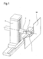
- a device for checking countersink dimensions is denoted in its entirety by the numeral 1.
- the device 1 comprises a measuring head 2 associated with a spindle 3 of a multi-axis process machine 4 (shown in Figure 1 ).
- the multi-axis process machine may be any numerically controlled machine of customary type.
- the multi-axis machine is the same machine that has made the countersinks whose dimensions are to be checked.
- the multi-axis machine 4 comprises a magazine (not illustrated) containing a plurality of tools (not illustrated), such as, for example, a reamer, a plurality of cutters, a countersinking tool and the measuring head 2.
- a plurality of tools such as, for example, a reamer, a plurality of cutters, a countersinking tool and the measuring head 2.
- the multi-axis machine 4 loads the most suitable tool from the magazine.
- the multi-axis machine 4 loads the measuring head 2 from the magazine and automatically associates it with the spindle 3.
- measuring or checking a countersink means measuring the depth of the countersink, that is to say, the distance along an axis coinciding with the axis of symmetry of the countersink between the outside edge and the inside edge of the countersink.
- the measuring head 2 comprises a contact element 5 that can be inserted at least partly in the countersink 101 to be measured.
- the contact element 5 comprises a punch 6 with a tip 6a having the shape of a pyramid with a circular base, that is to say, a conical shape.
- the tip 6a is the part of the contact element designed to be inserted into the countersink 101.
- the conical tip 6a of the contact element 5 has the same taper as the countersink 101 and is removably fastened, for example by screws, to the rest of the punch 6.
- the conical tip 6a can be changed with another one matching the taper of the countersink.
- the device 1 also comprises a comparator element 7 designed to detect the extent to which the contact element 5 is inserted into the countersink 101, that is to say, to detect the depth reached by the punch 6 inside the countersink 101.
- a processing unit (not illustrated) is operatively associated with the spindle 3 and controls spindle movements in such a way as to position the measuring head 2 at each of the countersinks 101 to be measured.
- the processing unit controls the movements of the spindle 3 by acting on the spindle drive means (not illustrated) on the basis of a positioning program which, in the preferred embodiment, coincides with the positioning program used to drive the spindle 3 during countersinking operations.
- the countersinks 101 can be measured without removing the panel in which the countersinks are made from the support used during countersinking operations, while at the same time being reasonably certain of the correct positioning of the measuring head 2 on the countersinks 101 to be measured.
- the comparator element 7 comprises a first portion 8 that can be moved translationally along a sliding direction Y relative to the contact element 5.
- the sliding direction Y is substantially parallel to the axis of symmetry of the countersink 101.
- the contact element 5 comprises an internal cylindrical cavity 9 that slidably receives the first portion 8 of the contact element 7 along the direction Y.
- the internal cavity 9, like the first portion 8 of the contact element 7, is substantially cylindrical and comprises an opening 10 to enable the mobile part 8 to be pushed out of the contact element 5 into contact with the edge of the countersink 101.
- a second portion 11 of the comparator element 7 is integral with the contact element 5 and is acted upon by the first portion 8.
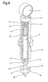
- the second portion 11 is attached to the contact element 5 on the opposite side relative to the opening 10 and comprises a mobile end 12 that extends into the cavity 9 of the contact element 5 (see Figure 4 ).
- the first portion 8 acts directly on the mobile end 12 of the second portion 11 of the comparator element 7. The movement of the mobile end 12 is therefore directly proportional to the sliding (withdrawal) of the first portion 8 relative to the contact element 5.
- the first portion 8 moves, and more specifically, withdraws when the conical tip of the contact element 5 is inserted into the countersink 101.
- the conical tip 6a has a plurality of slots 16 through which protrude an equal number of protuberances 17 of the first portion 8 of the comparator element 7.
- protuberances, or petals 17, extend towards the opening 10 and pass through the slots 16 in the conical tip 6a to abut the edge of the countersink 101.
- the petals 17 come into contact with the edge of the countersink and, as the conical tip 6a goes further into the countersink, the first portion 8 of the comparator element 7, that is to say, the portion on which the petals 17 are mounted, withdraws along the direction Y inside the cavity 9.
- the withdrawal movement and, more specifically, the extent of the withdrawal, is detected by the second portion 11 of the contact element 7 as a measure of the depth of the countersink 101.
- the measuring head 2 also comprises activating means 18 for activating transmission of the countersink depth measurement to a remote station.
- the remote station may be embodied, for example, by a computer for receiving the measurement readings of each countersink 101 and comparing them with predetermined design and tolerance values to determine whether or not the countersink measurement falls within certification requirements.
- the signal transmission activation means 18 make it possible to send a single signal indicating the actual countersink 101 measurement (that is to say, the maximum extent to which the first, mobile portion 8 of the comparator element 7 withdraws) instead of a plurality of signals each indicating the gradually increasing extent to which the first portion 8 of the comparator element 7 withdraws.
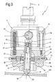
- Operation of the activation means 18 contemplates the division of the measuring head 2 into two half parts 2a, 2b ( Figures 2 and 3 ).
- the contact element 5 and the comparator element 7 are adjustably mounted on the first half part 2a along the direction Y in such a way that they can slide relative to the second half part 2b of the measuring head 2, also along the direction Y.
- the second half part 2b is attached to the first half part 2a in such a way as to have only one degree of freedom and, more specifically, in such a way that the two half parts 2a, 2b are connected to each other slidably along the direction Y.
- connection comprises one or more sliding guides 19 extending between the first and the second half part 2a and 2b (see Figures 2 and 3 ).
- the elastic element 20 comprises one or more springs extending parallel to the sliding guides 19.
- a microswitch 21 is provided between the first and the second half part 2a and 2b to be activated when the two half parts 2a, 2b move close to each other.
- the microswitch 21 may be of any type, that is to say, mechanical, electrical, electromechanical, magnetic or optical.
- pushing the measuring head 2 further towards the inside of the countersink 101 causes the elastic element 20 to yield in such a way that the two half parts 2a, 2b move closer together. This closing in movement activates the microswitch 21 to enable the measurement signal from the second portion 11 of the comparator element 7 to be transmitted.
- the device 1 further comprises a floating member 22 operating between the contact element 5 and the spindle 3.
- the floating member 22 provides the connection between the spindle 3 and the contact element 5 with at least one, and preferably three, further degrees of freedom.
- the floating member 22 operates between the outside surfaces of the punch 6 and the first half part 2a of the measuring head 2 ( Figures 2 and 3 ).
- the floating member 22 also provides at least one, and preferably three, further degrees of freedom for the connection between the spindle 3 and the comparator element 7, since the latter is partly integral with the punch 6 (second portion 11) and partly slidable along the direction Y relative to the inside of the punch (first portion 8).
- the floating member 22 comprises a first component 23 connected to the contact element 5 and slidable in a plane P1 substantially perpendicular to the direction Y.
- the first component 23 comprises a ring with a polygonal shape, preferably quadrangular or hexagonal, seated in a recess 24 formed in the first half part 2a of the measuring head 2 and facing a cavity 2c of the first half part 2a in which the punch 6 is inserted.
- the recess 24 is shaped to match the ring 23 and therefore has flat walls.
- the punch 6 can move in the plane P1 relative to the first half part 2a and, hence, relative to the spindle 3, compensating for any alignment errors between the spindle 3 and the axis of the countersink 101.
- the floating member 22 also comprises a second component 26 rotatably connected relative to the contact element 5 along a first axis X1 substantially perpendicular to the direction Y and rotatably connected to the spindle 3 along the first axis X1.
- the second component 26 comprises a ring 27 integral with two pins 28 spaced at 180° from each other and lying along the first axis X1.
- the two pins 28 are inserted in holes formed in the outside surface of the punch 6 in such a way that the ring 27, or rather, the punch 6, is rotatable about the first axis X1.
- the axis X1 is contained in the above mentioned plane P1.
- the ring 27 of the second component 26 also comprises two additional pins 29 spaced at 180° from each other and at 90° from the pins 28.
- the additional pins 29 are inserted in respective holes and operate between the ring 27 of the second component and the ring 23 constituting the first component.
- the second component 26 can rotate about a second axis X2, perpendicular to the first axis X1 and also contained in the plane P1.
- the contact element 5 and the comparator element 7 can rotate about two axes X1, X2 relative to the first half part 2a of the measuring head 2 and, hence, relative to the spindle 3, compensating for any alignment errors during positioning of the contact element 5 on the countersink 101.
- the surface of the punch that is in contact with the second component 26 is rounded, while the surface of the second component that is contact with the punch 6 is flat.
- the former has a rounded surface and the latter a flat vertical surface.
- the spindle 3 moves the measuring head 2 close to the countersink to be measured and, more specifically, moves the conical tip 6a of the punch 6 close to the mouth of the countersink 101 ( Figure 2 ).
- the conical tip 6a starts going into the countersink 101 and the petals 17 of the first portion 8 of the comparator element 7 come into contact with the edge of the countersink 101.
- the first portion 8 thus starts to withdraw along the direction Y under the action of the pushing force exerted by the spindle 3.
- the further pushing force applied to the measuring head 2 towards the inside of the countersink 101 causes the elastic element 20 to yield in such a way that the two half parts 2a, 2b of the measuring head 2 move closer together.
- This closing in movement activates the microswitch 21 which enables the measurement signal to be transmitted to the remote station.
- each measuring cycle is preceded by the measurement of a master countersink whose depth is known exactly so as to precisely calibrate the measuring head 2.
- reaction force exerted by the part of the countersink on which the conical tip 6a of the punch 6 discharges the force transmitted by the spindle has components directed both in the Y direction and in a direction perpendicular to the Y direction, that is to say, in the plane P1.
- This reaction force is discharged on the floating member 22, and, more specifically, on its mobile parts.
- the conical tip 6a of the punch 6 by entering the countersink 101, causes the punch 6 to move rotationally and translationally along a direction perpendicular to the direction Y until the conical wall of the tip 6a makes snug contact with the conical wall of the countersink 101, guaranteeing the perfect alignment of the countersink axis with the axis of the comparator and contact elements 7 and 5 even if initially misaligned ( Figure 3 ).
- the invention achieves the proposed aims.
- the device 1 for checking countersink dimensions achieves a high level of precision and reliability, since correct measurement does not depend on the operator's skill but, on the contrary, is performed in a fully automatic and perfectly repeatable manner.
- the floating member makes it possible to correct positioning errors of the measuring head relative to the axis of the countersink.
- the device 1 for checking countersink dimensions significantly reduces countersink checking times since the measuring procedure is fully automated and there is no need to move the panel in which the countersinks are made or to erect scaffolding to gain access to the countersinks.
Landscapes
- Physics & Mathematics (AREA)
- General Physics & Mathematics (AREA)
- Engineering & Computer Science (AREA)
- Mechanical Engineering (AREA)
- A Measuring Device Byusing Mechanical Method (AREA)
- Analysing Materials By The Use Of Radiation (AREA)
Claims (8)
- Vorrichtung zur Überprüfung von Senkerabmessungen, wobei die Vorrichtung einen Messkopf (2), der an eine Spindel (3) einer mehrachsigen Bearbeitungsmaschine (4) angeschlossen ist, und eine Verarbeitungseinheit, die an die Spindel (3) zur Steuerung der Spindelbewegungen wirksam angeschlossen ist, umfasst, wobei der Messkopf (2) ein Kontaktelement (5), das mindestens teilweise in einen Senker (101) eingeführt werden kann, und ein Komparatorelement (7) zum Erfassen des Ausmaßes umfasst, zu dem das Kontaktelement (5) in den Senker (101) eingeführt ist,
wobei die Vorrichtung ein frei bewegliches Glied (22) umfasst, das zwischen dem Kontaktelement (5) und der Spindel (3) wirkt, um die Verbindung zwischen der Spindel (3) und dem Kontaktelement (5) mit mindestens zwei Grad Freiraum bereitzustellen,
wobei das frei bewegliche Glied (22) außerdem zwischen dem Komparatorelement (7) und der Spindel (3) wirkt, um die Verbindung zwischen der Spindel (3) und dem Komparatorelement (7) mit mindestens zwei Grad Freiraum bereitzustellen. - Vorrichtung nach Anspruch 1, dadurch gekennzeichnet, dass das Komparatorelement (7) einen ersten Abschnitt (8) umfasst, der verschiebbar mit dem Kontaktelement (5) entlang einer Verschiebungsrichtung (Y) verbunden ist, die im Wesentlichen parallel zur Achse des Senkers (101) ist, wobei der erste Abschnitt (8) derart gestaltet ist, dass er an die Kante des Senkers (101) anstößt und sich während des Einführens des Kontaktelements (5) zurückzieht.
- Vorrichtung nach Anspruch 2, dadurch gekennzeichnet, dass das Komparatorelement (7) einen zweiten Abschnitt (11) umfasst, der einstückig mit dem Kontaktelement (5) ausgebildet ist und ein Ende (12) aufweist, das sich in Kontakt mit dem ersten Abschnitt (8) bewegt, um das Ausmaß zu erfassen, zu dem sich der erste Abschnitt (8) zurückzieht.
- Vorrichtung nach Anspruch 3, dadurch gekennzeichnet, dass der erste Abschnitt (8) des Komparatorelements (7) einen Zylinder umfasst, der in einen hohlen Zylinder (9) passt, der einen Abschnitt des Kontaktelements (5) bildet, wobei der Zylinder drei Zungen (17) umfasst, die aus dem hohlen Zylinder (9) herausragen und derart gestaltet sind, dass sie in Kontakt mit der Kante des Senkers (101) kommen.
- Vorrichtung nach Anspruch 2, dadurch gekennzeichnet, dass das frei bewegliche Glied (22) einen ersten Bestandteil (23) umfasst, der mit dem Kontaktelement (5) entlang einer Ebene (P1) verbunden ist, die im Wesentlichen lotrecht zur Verschiebungsrichtung (Y) des Komparatorelements (7) und in Bezug auf die Spindel (3) in der ersten Ebene (P1) verschiebbar ist.
- Vorrichtung nach Anspruch 5, dadurch gekennzeichnet, dass das frei bewegliche Glied (22) einen zweiten Bestandteil (26) umfasst, der in Bezug auf das Kontaktelement (5) drehbar um eine erste Achse (X1) verbunden ist, die im Wesentlichen zur Verschiebungsrichtung (Y) des Komparatorelements (7) lotrecht ist, und mit der Spindel (3) drehbar um die erste Achse (X1) verbunden ist.
- Vorrichtung nach Anspruch 6, dadurch gekennzeichnet, dass die erste Achse (X1) in der Ebene (P1) enthalten ist und dass der zweite Bestandteil (26) drehbar mit dem ersten Bestandteil (23) entlang einer zweiten Achse (X2) verbunden ist, die lotrecht zur ersten Achse (X1) und in der Ebene (P1) enthalten ist.
- Vorrichtung nach Anspruch 2, dadurch gekennzeichnet, dass der Messkopf (2) einen ersten halben Teil (2a) umfasst, und einen zweiten halben Teil (2b), der in Bezug auf den ersten halben Teil (2a) entlang der Verschiebungsrichtung (Y) des Komparatorelements (7) verschiebbar ist, Aktivierungsmittel (18), die sich zwischen den beiden halben Teilen (2a, 2b) zur Aktivierung einer Übertragung der Messung vom Komparatorelement (7) an eine entfernte Station befinden und aktiviert werden, wenn die beiden halben Teile (2a, 2b) sich nah auf einander zubewegen.
Applications Claiming Priority (1)
| Application Number | Priority Date | Filing Date | Title |
|---|---|---|---|
| IT000451A ITBO20070451A1 (it) | 2007-06-29 | 2007-06-29 | Dispositivo di verifica delle dimensioni di svasature. |
Publications (2)
| Publication Number | Publication Date |
|---|---|
| EP2009388A1 EP2009388A1 (de) | 2008-12-31 |
| EP2009388B1 true EP2009388B1 (de) | 2011-06-22 |
Family
ID=39671652
Family Applications (1)
| Application Number | Title | Priority Date | Filing Date |
|---|---|---|---|
| EP08104368A Active EP2009388B1 (de) | 2007-06-29 | 2008-06-11 | Vorrichtung zur Überprüfung von Senkerabmessungen |
Country Status (5)
| Country | Link |
|---|---|
| US (1) | US7743526B2 (de) |
| EP (1) | EP2009388B1 (de) |
| CN (1) | CN201261146Y (de) |
| ES (1) | ES2367458T3 (de) |
| IT (1) | ITBO20070451A1 (de) |
Families Citing this family (10)
| Publication number | Priority date | Publication date | Assignee | Title |
|---|---|---|---|---|
| CN101898312B (zh) * | 2010-07-07 | 2011-11-09 | 益阳橡胶塑料机械集团有限公司 | 轴类工件辅助测量夹具 |
| US8464434B1 (en) * | 2010-09-15 | 2013-06-18 | The Boeing Company | Hole and countersink measurement system |
| US8713980B2 (en) * | 2011-05-31 | 2014-05-06 | Stolle Machinery Company, Llc | Automatic domer positioning in a bodymaker |
| DE102011115819B4 (de) * | 2011-10-13 | 2013-07-04 | Premium Aerotec Gmbh | Nietvorrichtung, Verfahren und zugehörige Verwendung zur Bewerkstelligung einer Mehrzahl von Nietungen entlang der Oberfläche eines Werkstückes |
| DE102013015685A1 (de) * | 2013-09-23 | 2015-03-26 | Man Diesel & Turbo Se | Werkzeugmaschine |
| JP5932006B1 (ja) | 2014-12-15 | 2016-06-08 | Dmg森精機株式会社 | 接触式位置測定器を用いた面取り穴径の測定方法 |
| EP3037193B1 (de) * | 2014-12-22 | 2020-03-18 | KUKA Systems Aerospace | Lochprüfvorrichtung |
| CN112247676B (zh) * | 2020-11-16 | 2025-02-11 | 无锡贝斯特精机股份有限公司 | 一种曲轴孔中心取正工装及取正方法 |
| AT524535B1 (de) * | 2021-01-15 | 2022-07-15 | Avl List Gmbh | Verfahren zur Korrektur einer Fehlausrichtung wenigstens eines Wellenstrangs |
| CN114323911A (zh) * | 2021-12-07 | 2022-04-12 | 东风汽车集团股份有限公司 | 一种压缩试样限位对中装置 |
Family Cites Families (15)
| Publication number | Priority date | Publication date | Assignee | Title |
|---|---|---|---|---|
| US3116560A (en) * | 1961-07-11 | 1964-01-07 | Western Electric Co | Gage for determining size and angle of countersink |
| US3940854A (en) * | 1974-03-27 | 1976-03-02 | Westinghouse Electric Corporation | Three axis precision measuring device |
| GB1597842A (en) * | 1977-02-07 | 1981-09-09 | Rolls Royce | Indexing mechanism |
| US4905378A (en) | 1985-08-26 | 1990-03-06 | Lockheed Corporation | Centralizing countersink gauge |
| US4809440A (en) * | 1988-02-11 | 1989-03-07 | Sunnen Products Company | In dial bore gages |
| DE4027637A1 (de) | 1990-08-31 | 1992-03-05 | Stiefelmayer Kg C | Geradfuehrung zur fuehrung des schlittens eines vorzugsweise dreidimensionalen mess- und/oder anreissgeraetes |
| US5475932A (en) * | 1992-09-24 | 1995-12-19 | Metrol Co., Ltd. | Shaft position sensor |
| US5758433A (en) * | 1996-04-23 | 1998-06-02 | The Boeing Company | Countersink depth gauge |
| IT1299955B1 (it) * | 1998-04-06 | 2000-04-04 | Marposs Spa | Testa per il controllo di dimensioni lineari di pezzi. |
| JP3633788B2 (ja) | 1998-07-13 | 2005-03-30 | 株式会社ミツトヨ | 測定装置 |
| TW555958B (en) | 2002-05-24 | 2003-10-01 | Hon Hai Prec Ind Co Ltd | Tool and method for measuring the depth of sinking holes |
| ITBO20030043A1 (it) * | 2003-01-31 | 2004-08-01 | Jobs Spa | Testa porta utensili per macchine utensili pluri asse |
| US6949057B2 (en) | 2003-09-02 | 2005-09-27 | The Boeing Company | Multi-function end effector |
| ITBO20040217A1 (it) * | 2004-04-16 | 2004-07-16 | Jobs Spa | Testa operatrice per macchine utensili pluriasse |
| US7363721B2 (en) | 2005-11-07 | 2008-04-29 | The Boeing Company | Countersink gauge having self-centering probe |
-
2007
- 2007-06-29 IT IT000451A patent/ITBO20070451A1/it unknown
-
2008
- 2008-06-11 EP EP08104368A patent/EP2009388B1/de active Active
- 2008-06-11 ES ES08104368T patent/ES2367458T3/es active Active
- 2008-06-30 US US12/216,173 patent/US7743526B2/en active Active
- 2008-06-30 CN CN200820125506.5U patent/CN201261146Y/zh not_active Expired - Fee Related
Also Published As
| Publication number | Publication date |
|---|---|
| CN201261146Y (zh) | 2009-06-24 |
| US7743526B2 (en) | 2010-06-29 |
| EP2009388A1 (de) | 2008-12-31 |
| ES2367458T3 (es) | 2011-11-03 |
| US20090063091A1 (en) | 2009-03-05 |
| ITBO20070451A1 (it) | 2008-12-30 |
Similar Documents
| Publication | Publication Date | Title |
|---|---|---|
| EP2009388B1 (de) | Vorrichtung zur Überprüfung von Senkerabmessungen | |
| EP1586414B1 (de) | Werkzeugspindelkopf mit einer Messvorrichtung zur Tiefenkontrolle | |
| CN114643482B (zh) | 监测装置、具有监测装置的夹紧系统和通过监测装置监测夹紧装置的方法 | |
| US4706372A (en) | Device for effecting automatic exchange of measuring tools in a measuring robot or machine | |
| US9199351B2 (en) | Drilling machine having hole measurement capability | |
| US10814403B2 (en) | Tool alignment device | |
| CN102387885B (zh) | 用于确保预设的加工深度的加工装置和方法 | |
| US6158929A (en) | Electronically triggered surface sensor unit | |
| US20150007668A1 (en) | Bond testing machine and cartridge for a bond testing machine comprising a plurality of test tools | |
| US9707656B2 (en) | Automated inspection system | |
| CN101094588B (zh) | 检测治具 | |
| JP2025035083A (ja) | 自動測定装置 | |
| CN114061521A (zh) | 工件的内孔外圆精密测量装置 | |
| US20250297843A1 (en) | Inner diameter measuring apparatus and system thereof | |
| US20230088695A1 (en) | Chuck | |
| JP2025035082A (ja) | 自動測定装置 | |
| EP1091822B1 (de) | Elektronisch auszulösende oberflächensensoreinheit | |
| JP5605514B2 (ja) | ワーク傾き検出機能付きローダ | |
| CN210426371U (zh) | 一种适于含能回转零件在机测量装置 | |
| EP4439000B1 (de) | Messgerät für profilstahl | |
| US6580956B1 (en) | Positioning system | |
| JP2022185919A (ja) | 計測装置及び計測方法 | |
| HK40000125A (en) | Accessory for centring tools on a machining appliance, centring method and centring assistance device comprising such an accessory |
Legal Events
| Date | Code | Title | Description |
|---|---|---|---|
| PUAI | Public reference made under article 153(3) epc to a published international application that has entered the european phase |
Free format text: ORIGINAL CODE: 0009012 |
|
| AK | Designated contracting states |
Kind code of ref document: A1 Designated state(s): AT BE BG CH CY CZ DE DK EE ES FI FR GB GR HR HU IE IS IT LI LT LU LV MC MT NL NO PL PT RO SE SI SK TR |
|
| AX | Request for extension of the european patent |
Extension state: AL BA MK RS |
|
| 17P | Request for examination filed |
Effective date: 20090313 |
|
| AKX | Designation fees paid |
Designated state(s): DE ES FR GB IT |
|
| GRAP | Despatch of communication of intention to grant a patent |
Free format text: ORIGINAL CODE: EPIDOSNIGR1 |
|
| GRAS | Grant fee paid |
Free format text: ORIGINAL CODE: EPIDOSNIGR3 |
|
| GRAA | (expected) grant |
Free format text: ORIGINAL CODE: 0009210 |
|
| AK | Designated contracting states |
Kind code of ref document: B1 Designated state(s): DE ES FR GB IT |
|
| REG | Reference to a national code |
Ref country code: GB Ref legal event code: FG4D |
|
| REG | Reference to a national code |
Ref country code: DE Ref legal event code: R096 Ref document number: 602008007736 Country of ref document: DE Effective date: 20110804 |
|
| REG | Reference to a national code |
Ref country code: ES Ref legal event code: FG2A Ref document number: 2367458 Country of ref document: ES Kind code of ref document: T3 Effective date: 20111103 |
|
| PLBE | No opposition filed within time limit |
Free format text: ORIGINAL CODE: 0009261 |
|
| STAA | Information on the status of an ep patent application or granted ep patent |
Free format text: STATUS: NO OPPOSITION FILED WITHIN TIME LIMIT |
|
| 26N | No opposition filed |
Effective date: 20120323 |
|
| REG | Reference to a national code |
Ref country code: DE Ref legal event code: R097 Ref document number: 602008007736 Country of ref document: DE Effective date: 20120323 |
|
| REG | Reference to a national code |
Ref country code: FR Ref legal event code: PLFP Year of fee payment: 9 |
|
| REG | Reference to a national code |
Ref country code: FR Ref legal event code: PLFP Year of fee payment: 10 |
|
| REG | Reference to a national code |
Ref country code: FR Ref legal event code: PLFP Year of fee payment: 11 |
|
| PGFP | Annual fee paid to national office [announced via postgrant information from national office to epo] |
Ref country code: DE Payment date: 20250626 Year of fee payment: 18 |
|
| PGFP | Annual fee paid to national office [announced via postgrant information from national office to epo] |
Ref country code: GB Payment date: 20250625 Year of fee payment: 18 |
|
| PGFP | Annual fee paid to national office [announced via postgrant information from national office to epo] |
Ref country code: FR Payment date: 20250625 Year of fee payment: 18 |
|
| PGFP | Annual fee paid to national office [announced via postgrant information from national office to epo] |
Ref country code: ES Payment date: 20250710 Year of fee payment: 18 |
|
| PGFP | Annual fee paid to national office [announced via postgrant information from national office to epo] |
Ref country code: IT Payment date: 20250626 Year of fee payment: 18 |