EP2009388B1 - Device for checking countersink dimensions - Google Patents
Device for checking countersink dimensions Download PDFInfo
- Publication number
- EP2009388B1 EP2009388B1 EP08104368A EP08104368A EP2009388B1 EP 2009388 B1 EP2009388 B1 EP 2009388B1 EP 08104368 A EP08104368 A EP 08104368A EP 08104368 A EP08104368 A EP 08104368A EP 2009388 B1 EP2009388 B1 EP 2009388B1
- Authority
- EP
- European Patent Office
- Prior art keywords
- countersink
- spindle
- contact element
- axis
- comparator
- Prior art date
- Legal status (The legal status is an assumption and is not a legal conclusion. Google has not performed a legal analysis and makes no representation as to the accuracy of the status listed.)
- Active
Links
Images


Classifications
-
- G—PHYSICS
- G01—MEASURING; TESTING
- G01B—MEASURING LENGTH, THICKNESS OR SIMILAR LINEAR DIMENSIONS; MEASURING ANGLES; MEASURING AREAS; MEASURING IRREGULARITIES OF SURFACES OR CONTOURS
- G01B3/00—Measuring instruments characterised by the use of mechanical techniques
- G01B3/22—Feeler-pin gauges, e.g. dial gauges
- G01B3/28—Depth gauges
-
- B—PERFORMING OPERATIONS; TRANSPORTING
- B23—MACHINE TOOLS; METAL-WORKING NOT OTHERWISE PROVIDED FOR
- B23Q—DETAILS, COMPONENTS, OR ACCESSORIES FOR MACHINE TOOLS, e.g. ARRANGEMENTS FOR COPYING OR CONTROLLING; MACHINE TOOLS IN GENERAL CHARACTERISED BY THE CONSTRUCTION OF PARTICULAR DETAILS OR COMPONENTS; COMBINATIONS OR ASSOCIATIONS OF METAL-WORKING MACHINES, NOT DIRECTED TO A PARTICULAR RESULT
- B23Q17/00—Arrangements for observing, indicating or measuring on machine tools
- B23Q17/20—Arrangements for observing, indicating or measuring on machine tools for indicating or measuring workpiece characteristics, e.g. contour, dimension, hardness
-
- G—PHYSICS
- G01—MEASURING; TESTING
- G01B—MEASURING LENGTH, THICKNESS OR SIMILAR LINEAR DIMENSIONS; MEASURING ANGLES; MEASURING AREAS; MEASURING IRREGULARITIES OF SURFACES OR CONTOURS
- G01B5/00—Measuring arrangements characterised by the use of mechanical techniques
- G01B5/18—Measuring arrangements characterised by the use of mechanical techniques for measuring depth
-
- B—PERFORMING OPERATIONS; TRANSPORTING
- B23—MACHINE TOOLS; METAL-WORKING NOT OTHERWISE PROVIDED FOR
- B23Q—DETAILS, COMPONENTS, OR ACCESSORIES FOR MACHINE TOOLS, e.g. ARRANGEMENTS FOR COPYING OR CONTROLLING; MACHINE TOOLS IN GENERAL CHARACTERISED BY THE CONSTRUCTION OF PARTICULAR DETAILS OR COMPONENTS; COMBINATIONS OR ASSOCIATIONS OF METAL-WORKING MACHINES, NOT DIRECTED TO A PARTICULAR RESULT
- B23Q2230/00—Special operations in a machine tool
- B23Q2230/002—Using the spindle for performing a non machining or non measuring operation, e.g. cleaning, actuating a mechanism
Definitions
- This invention relates to a device for checking the size of countersinks.
- the invention applies in particular to dimensional checking for machining process certification of very large parts.
- a typical application of the invention is dimensional checking of countersinks made by numerically controlled machines on large panels such as, for example, aircraft wing panels and fuselage parts.
- An aircraft wing panel or a part of a fuselage requires several hundred or even thousands of countersinks to accommodate the heads of the rivets used to join the wing panel to the wing ribs or to fasten a fuselage panel to the fuselage frame.
- countersinks are usually made by numerically controlled machines where a suitable tool head machines the panel as required.
- Assembly houses require certification of every part they assemble to ensure that all prior machining processes have been performed to specifications and will not invalidate the final assembly.
- checking is carried out by one or more operators with gauge in hand to measure each single countersink.
- checking the countersinks in the manner described above is subject to human error and to the fact that the gauges used, in order to provide a reliable reading, must be positioned on the countersink with extreme precision and meticulous care.
- a tool-head for a multi-axis machine which incorporates a tool-head rotatable about the tool axis and attached to the spindle of a spindle head.
- the tool head also comprises a stop cage element mounted slidably to the tool-holder, which is furnished with a collar presenting an active surface set transversely to the tool axis and offered to the surface of a work-piece.
- the stop cage element alternates between a first operating position, in which the active surface is located forward of a countersink portion presented by the tool, considered in relation to the feed direction of the spindle-head as it approaches the surface of the work, and a second position in which the countersink portion will be located forward of the active surface at least in part.
- the axial position of the stop cage element relative to the tool-holder is monitored continuously by a sensing system.
- a control unit measures the displacement of the stop cage element relative to the spindle-head which corresponds in practice to the penetration of a frustoconical cutting portion and therefore to the depth of the countersink.
- control unit is focused on a comparator element whose contact element meets the respective countersink by displaying the measure detected on the respective display.
- the document US2005/0491126 refers to a multifunction end effector which includes a plurality of tool change mechanism in a housing in which a spindle is also mounted for translation along an axis of the spindle.
- the tools mounted in the tool holders include a drill bit, a countersink tool, and a fastener insertion tool.
- the document DE 4027637 refers to a measuring measuring device movable along the edge of a plate.
- the measuring device comprises a tool-holder which is secured to a transverse arm protruding from a clamp on an upright post.
- the document DE199324466 shows a measurement arrangement having a base, a probe and a movement mechanism for relative movement of the base and probe.
- the Applicant has found that the instruments used for measuring the countersinks, and the measuring process itself, can be improved in several respects, especially in terms of measurement time and reliability.
- the basic purpose of the present invention is to provide a device for checking countersink dimensions capable of overcoming the above mentioned drawbacks.
- this invention has for an aim to provide a device for checking countersink dimensions offering a high degree of precision and reliability.
- Another aim of the invention is to provide a device for checking countersink dimensions that reduces the time required for checking the countersinks.
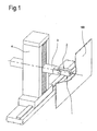
- a device for checking countersink dimensions is denoted in its entirety by the numeral 1.
- the device 1 comprises a measuring head 2 associated with a spindle 3 of a multi-axis process machine 4 (shown in Figure 1 ).
- the multi-axis process machine may be any numerically controlled machine of customary type.
- the multi-axis machine is the same machine that has made the countersinks whose dimensions are to be checked.
- the multi-axis machine 4 comprises a magazine (not illustrated) containing a plurality of tools (not illustrated), such as, for example, a reamer, a plurality of cutters, a countersinking tool and the measuring head 2.
- a plurality of tools such as, for example, a reamer, a plurality of cutters, a countersinking tool and the measuring head 2.
- the multi-axis machine 4 loads the most suitable tool from the magazine.
- the multi-axis machine 4 loads the measuring head 2 from the magazine and automatically associates it with the spindle 3.
- measuring or checking a countersink means measuring the depth of the countersink, that is to say, the distance along an axis coinciding with the axis of symmetry of the countersink between the outside edge and the inside edge of the countersink.
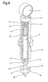
- the measuring head 2 comprises a contact element 5 that can be inserted at least partly in the countersink 101 to be measured.
- the contact element 5 comprises a punch 6 with a tip 6a having the shape of a pyramid with a circular base, that is to say, a conical shape.
- the tip 6a is the part of the contact element designed to be inserted into the countersink 101.
- the conical tip 6a of the contact element 5 has the same taper as the countersink 101 and is removably fastened, for example by screws, to the rest of the punch 6.
- the conical tip 6a can be changed with another one matching the taper of the countersink.
- the device 1 also comprises a comparator element 7 designed to detect the extent to which the contact element 5 is inserted into the countersink 101, that is to say, to detect the depth reached by the punch 6 inside the countersink 101.
- a processing unit (not illustrated) is operatively associated with the spindle 3 and controls spindle movements in such a way as to position the measuring head 2 at each of the countersinks 101 to be measured.
- the processing unit controls the movements of the spindle 3 by acting on the spindle drive means (not illustrated) on the basis of a positioning program which, in the preferred embodiment, coincides with the positioning program used to drive the spindle 3 during countersinking operations.
- the countersinks 101 can be measured without removing the panel in which the countersinks are made from the support used during countersinking operations, while at the same time being reasonably certain of the correct positioning of the measuring head 2 on the countersinks 101 to be measured.
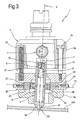
- the comparator element 7 comprises a first portion 8 that can be moved translationally along a sliding direction Y relative to the contact element 5.
- the sliding direction Y is substantially parallel to the axis of symmetry of the countersink 101.
- the contact element 5 comprises an internal cylindrical cavity 9 that slidably receives the first portion 8 of the contact element 7 along the direction Y.
- the internal cavity 9, like the first portion 8 of the contact element 7, is substantially cylindrical and comprises an opening 10 to enable the mobile part 8 to be pushed out of the contact element 5 into contact with the edge of the countersink 101.
- a second portion 11 of the comparator element 7 is integral with the contact element 5 and is acted upon by the first portion 8.
- the second portion 11 is attached to the contact element 5 on the opposite side relative to the opening 10 and comprises a mobile end 12 that extends into the cavity 9 of the contact element 5 (see Figure 4 ).
- the first portion 8 acts directly on the mobile end 12 of the second portion 11 of the comparator element 7. The movement of the mobile end 12 is therefore directly proportional to the sliding (withdrawal) of the first portion 8 relative to the contact element 5.
- the first portion 8 moves, and more specifically, withdraws when the conical tip of the contact element 5 is inserted into the countersink 101.
- the conical tip 6a has a plurality of slots 16 through which protrude an equal number of protuberances 17 of the first portion 8 of the comparator element 7.
- protuberances, or petals 17, extend towards the opening 10 and pass through the slots 16 in the conical tip 6a to abut the edge of the countersink 101.
- the petals 17 come into contact with the edge of the countersink and, as the conical tip 6a goes further into the countersink, the first portion 8 of the comparator element 7, that is to say, the portion on which the petals 17 are mounted, withdraws along the direction Y inside the cavity 9.
- the withdrawal movement and, more specifically, the extent of the withdrawal, is detected by the second portion 11 of the contact element 7 as a measure of the depth of the countersink 101.
- the measuring head 2 also comprises activating means 18 for activating transmission of the countersink depth measurement to a remote station.
- the remote station may be embodied, for example, by a computer for receiving the measurement readings of each countersink 101 and comparing them with predetermined design and tolerance values to determine whether or not the countersink measurement falls within certification requirements.
- the signal transmission activation means 18 make it possible to send a single signal indicating the actual countersink 101 measurement (that is to say, the maximum extent to which the first, mobile portion 8 of the comparator element 7 withdraws) instead of a plurality of signals each indicating the gradually increasing extent to which the first portion 8 of the comparator element 7 withdraws.
- Operation of the activation means 18 contemplates the division of the measuring head 2 into two half parts 2a, 2b ( Figures 2 and 3 ).
- the contact element 5 and the comparator element 7 are adjustably mounted on the first half part 2a along the direction Y in such a way that they can slide relative to the second half part 2b of the measuring head 2, also along the direction Y.
- the second half part 2b is attached to the first half part 2a in such a way as to have only one degree of freedom and, more specifically, in such a way that the two half parts 2a, 2b are connected to each other slidably along the direction Y.
- connection comprises one or more sliding guides 19 extending between the first and the second half part 2a and 2b (see Figures 2 and 3 ).
- the elastic element 20 comprises one or more springs extending parallel to the sliding guides 19.
- a microswitch 21 is provided between the first and the second half part 2a and 2b to be activated when the two half parts 2a, 2b move close to each other.
- the microswitch 21 may be of any type, that is to say, mechanical, electrical, electromechanical, magnetic or optical.
- pushing the measuring head 2 further towards the inside of the countersink 101 causes the elastic element 20 to yield in such a way that the two half parts 2a, 2b move closer together. This closing in movement activates the microswitch 21 to enable the measurement signal from the second portion 11 of the comparator element 7 to be transmitted.
- the device 1 further comprises a floating member 22 operating between the contact element 5 and the spindle 3.
- the floating member 22 provides the connection between the spindle 3 and the contact element 5 with at least one, and preferably three, further degrees of freedom.
- the floating member 22 operates between the outside surfaces of the punch 6 and the first half part 2a of the measuring head 2 ( Figures 2 and 3 ).
- the floating member 22 also provides at least one, and preferably three, further degrees of freedom for the connection between the spindle 3 and the comparator element 7, since the latter is partly integral with the punch 6 (second portion 11) and partly slidable along the direction Y relative to the inside of the punch (first portion 8).
- the floating member 22 comprises a first component 23 connected to the contact element 5 and slidable in a plane P1 substantially perpendicular to the direction Y.
- the first component 23 comprises a ring with a polygonal shape, preferably quadrangular or hexagonal, seated in a recess 24 formed in the first half part 2a of the measuring head 2 and facing a cavity 2c of the first half part 2a in which the punch 6 is inserted.
- the recess 24 is shaped to match the ring 23 and therefore has flat walls.
- the punch 6 can move in the plane P1 relative to the first half part 2a and, hence, relative to the spindle 3, compensating for any alignment errors between the spindle 3 and the axis of the countersink 101.
- the floating member 22 also comprises a second component 26 rotatably connected relative to the contact element 5 along a first axis X1 substantially perpendicular to the direction Y and rotatably connected to the spindle 3 along the first axis X1.
- the second component 26 comprises a ring 27 integral with two pins 28 spaced at 180° from each other and lying along the first axis X1.
- the two pins 28 are inserted in holes formed in the outside surface of the punch 6 in such a way that the ring 27, or rather, the punch 6, is rotatable about the first axis X1.
- the axis X1 is contained in the above mentioned plane P1.
- the ring 27 of the second component 26 also comprises two additional pins 29 spaced at 180° from each other and at 90° from the pins 28.
- the additional pins 29 are inserted in respective holes and operate between the ring 27 of the second component and the ring 23 constituting the first component.
- the second component 26 can rotate about a second axis X2, perpendicular to the first axis X1 and also contained in the plane P1.
- the contact element 5 and the comparator element 7 can rotate about two axes X1, X2 relative to the first half part 2a of the measuring head 2 and, hence, relative to the spindle 3, compensating for any alignment errors during positioning of the contact element 5 on the countersink 101.
- the surface of the punch that is in contact with the second component 26 is rounded, while the surface of the second component that is contact with the punch 6 is flat.
- the former has a rounded surface and the latter a flat vertical surface.
- the spindle 3 moves the measuring head 2 close to the countersink to be measured and, more specifically, moves the conical tip 6a of the punch 6 close to the mouth of the countersink 101 ( Figure 2 ).
- the conical tip 6a starts going into the countersink 101 and the petals 17 of the first portion 8 of the comparator element 7 come into contact with the edge of the countersink 101.
- the first portion 8 thus starts to withdraw along the direction Y under the action of the pushing force exerted by the spindle 3.
- the further pushing force applied to the measuring head 2 towards the inside of the countersink 101 causes the elastic element 20 to yield in such a way that the two half parts 2a, 2b of the measuring head 2 move closer together.
- This closing in movement activates the microswitch 21 which enables the measurement signal to be transmitted to the remote station.
- each measuring cycle is preceded by the measurement of a master countersink whose depth is known exactly so as to precisely calibrate the measuring head 2.
- reaction force exerted by the part of the countersink on which the conical tip 6a of the punch 6 discharges the force transmitted by the spindle has components directed both in the Y direction and in a direction perpendicular to the Y direction, that is to say, in the plane P1.
- This reaction force is discharged on the floating member 22, and, more specifically, on its mobile parts.
- the conical tip 6a of the punch 6 by entering the countersink 101, causes the punch 6 to move rotationally and translationally along a direction perpendicular to the direction Y until the conical wall of the tip 6a makes snug contact with the conical wall of the countersink 101, guaranteeing the perfect alignment of the countersink axis with the axis of the comparator and contact elements 7 and 5 even if initially misaligned ( Figure 3 ).
- the invention achieves the proposed aims.
- the device 1 for checking countersink dimensions achieves a high level of precision and reliability, since correct measurement does not depend on the operator's skill but, on the contrary, is performed in a fully automatic and perfectly repeatable manner.
- the floating member makes it possible to correct positioning errors of the measuring head relative to the axis of the countersink.
- the device 1 for checking countersink dimensions significantly reduces countersink checking times since the measuring procedure is fully automated and there is no need to move the panel in which the countersinks are made or to erect scaffolding to gain access to the countersinks.
Description
- This invention relates to a device for checking the size of countersinks.
- The invention applies in particular to dimensional checking for machining process certification of very large parts.
- A typical application of the invention is dimensional checking of countersinks made by numerically controlled machines on large panels such as, for example, aircraft wing panels and fuselage parts.
- An aircraft wing panel or a part of a fuselage requires several hundred or even thousands of countersinks to accommodate the heads of the rivets used to join the wing panel to the wing ribs or to fasten a fuselage panel to the fuselage frame.
- These countersinks are usually made by numerically controlled machines where a suitable tool head machines the panel as required.
- Certification of machined parts is becoming more and more a requirement as part machining and final assembly are performed by different companies.
- Assembly houses require certification of every part they assemble to ensure that all prior machining processes have been performed to specifications and will not invalidate the final assembly.
- At present, for certification to be obtained, it is sufficient to precisely measure only some of the countersinks made, the validity of the machining process in its entirety being determined a posteriori and only on a statistical basis.
- Since machining tolerances, for example in aeronautical applications, are now required to be within 5 hundredths of a millimetre, the statistical certification process is no longer accepted and measurement of every single countersink is instead required.
- In prior art, checking is carried out by one or more operators with gauge in hand to measure each single countersink.
- This process, besides being very slow and therefore expensive, requires the provision of scaffolding and other equipment to allow access to the part of the panel where measurements are to be performed and to enable the operator to reach each countersink to be measured.
- Moreover, checking the countersinks in the manner described above is subject to human error and to the fact that the gauges used, in order to provide a reliable reading, must be positioned on the countersink with extreme precision and meticulous care.
- It is also known from document
EP1442837A1 a tool-head for a multi-axis machine which incorporates a tool-head rotatable about the tool axis and attached to the spindle of a spindle head. The tool head also comprises a stop cage element mounted slidably to the tool-holder, which is furnished with a collar presenting an active surface set transversely to the tool axis and offered to the surface of a work-piece. The stop cage element alternates between a first operating position, in which the active surface is located forward of a countersink portion presented by the tool, considered in relation to the feed direction of the spindle-head as it approaches the surface of the work, and a second position in which the countersink portion will be located forward of the active surface at least in part. The axial position of the stop cage element relative to the tool-holder is monitored continuously by a sensing system. A control unit measures the displacement of the stop cage element relative to the spindle-head which corresponds in practice to the penetration of a frustoconical cutting portion and therefore to the depth of the countersink. - Other systems able to control countersinks are disclosed within the documents
US2003/217479 A1 ,US-A-4905378 andUS2007/101597 A1 . In particular, the control unit disclosed is focused on a comparator element whose contact element meets the respective countersink by displaying the measure detected on the respective display. - The document
US2005/0491126 refers to a multifunction end effector which includes a plurality of tool change mechanism in a housing in which a spindle is also mounted for translation along an axis of the spindle. The tools mounted in the tool holders include a drill bit, a countersink tool, and a fastener insertion tool. - The document
DE 4027637 refers to a measuring measuring device movable along the edge of a plate. The measuring device comprises a tool-holder which is secured to a transverse arm protruding from a clamp on an upright post. - The document
DE199324466 shows a measurement arrangement having a base, a probe and a movement mechanism for relative movement of the base and probe. - The Applicant has found that the instruments used for measuring the countersinks, and the measuring process itself, can be improved in several respects, especially in terms of measurement time and reliability.
- In this situation, the basic purpose of the present invention is to provide a device for checking countersink dimensions capable of overcoming the above mentioned drawbacks.
- In particular, this invention has for an aim to provide a device for checking countersink dimensions offering a high degree of precision and reliability.
- Another aim of the invention is to provide a device for checking countersink dimensions that reduces the time required for checking the countersinks.
- The technical purpose and aims specified are substantially achieved by a device for checking countersink dimensions characterized in that it comprises the technical characteristics described in
independent claim 1. - Further embodiments are defined by the dependent claims.
- A preferred non-limiting embodiment of a device for checking the size of countersinks will now be described in further detail without restricting the scope of the inventive concept with reference to the accompanying drawings, in which:
-
Figure 1 is a side view of a device according to the invention for checking countersink dimensions; -
Figures 2 and3 are section views of a detail fromFigure 1 in two different operating positions; -
Figure 4 is a perspective view, with some parts cut away, of a detail fromFigures 2 and3 ; and -
Figure 5 is a section view through a plane perpendicular to the section plane ofFigures 2 and3 and illustrating the same detail as those two figures. - With reference to the accompanying drawings, a device for checking countersink dimensions is denoted in its entirety by the
numeral 1. - The
device 1 comprises ameasuring head 2 associated with aspindle 3 of a multi-axis process machine 4 (shown inFigure 1 ). The multi-axis process machine may be any numerically controlled machine of customary type. In the preferred embodiment, the multi-axis machine is the same machine that has made the countersinks whose dimensions are to be checked. - In the preferred embodiment, therefore, the
multi-axis machine 4 comprises a magazine (not illustrated) containing a plurality of tools (not illustrated), such as, for example, a reamer, a plurality of cutters, a countersinking tool and themeasuring head 2. - Depending on the machining process to be performed on the part (labelled 100 in
Figure 1 and represented as a thin panel) themulti-axis machine 4 loads the most suitable tool from the magazine. In the case of this invention, themulti-axis machine 4 loads the measuringhead 2 from the magazine and automatically associates it with thespindle 3. - It should be stressed that in the context of this invention, measuring or checking a countersink means measuring the depth of the countersink, that is to say, the distance along an axis coinciding with the axis of symmetry of the countersink between the outside edge and the inside edge of the countersink.
- The
measuring head 2 comprises acontact element 5 that can be inserted at least partly in thecountersink 101 to be measured. - In the example embodiment illustrated in the accompanying drawings, the
contact element 5 comprises apunch 6 with atip 6a having the shape of a pyramid with a circular base, that is to say, a conical shape. Thetip 6a is the part of the contact element designed to be inserted into thecountersink 101. - More specifically, the
conical tip 6a of thecontact element 5 has the same taper as thecountersink 101 and is removably fastened, for example by screws, to the rest of thepunch 6. Thus, to check countersinks with a different taper, theconical tip 6a can be changed with another one matching the taper of the countersink. - The
device 1 also comprises acomparator element 7 designed to detect the extent to which thecontact element 5 is inserted into thecountersink 101, that is to say, to detect the depth reached by thepunch 6 inside thecountersink 101. - A processing unit (not illustrated) is operatively associated with the
spindle 3 and controls spindle movements in such a way as to position the measuringhead 2 at each of thecountersinks 101 to be measured. - The processing unit controls the movements of the
spindle 3 by acting on the spindle drive means (not illustrated) on the basis of a positioning program which, in the preferred embodiment, coincides with the positioning program used to drive thespindle 3 during countersinking operations. - In this way, the
countersinks 101 can be measured without removing the panel in which the countersinks are made from the support used during countersinking operations, while at the same time being reasonably certain of the correct positioning of the measuringhead 2 on thecountersinks 101 to be measured. - The
comparator element 7 comprises afirst portion 8 that can be moved translationally along a sliding direction Y relative to thecontact element 5. The sliding direction Y is substantially parallel to the axis of symmetry of thecountersink 101. - In particular (see
Figure 4 ), thecontact element 5 comprises an internalcylindrical cavity 9 that slidably receives thefirst portion 8 of thecontact element 7 along the direction Y. Theinternal cavity 9, like thefirst portion 8 of thecontact element 7, is substantially cylindrical and comprises anopening 10 to enable themobile part 8 to be pushed out of thecontact element 5 into contact with the edge of thecountersink 101. - A
second portion 11 of thecomparator element 7 is integral with thecontact element 5 and is acted upon by thefirst portion 8. - In particular, the
second portion 11 is attached to thecontact element 5 on the opposite side relative to theopening 10 and comprises amobile end 12 that extends into thecavity 9 of the contact element 5 (seeFigure 4 ). Thefirst portion 8 acts directly on themobile end 12 of thesecond portion 11 of thecomparator element 7. The movement of themobile end 12 is therefore directly proportional to the sliding (withdrawal) of thefirst portion 8 relative to thecontact element 5. - To avoid uncontrolled movements of the
first portion 8 relative to themobile end 12 of thesecond portion 11 of thecomparator element 7, there is aspring 13 operating between anupper wall 14 of thecavity 9 and ashoulder 15 of the cylindrical element constituting thefirst portion 8 of the comparator element 7 (Figure 4 ). Thespring 13 pushes the first,mobile portion 8 constantly towards the opening 10. - As mentioned above, the
first portion 8 moves, and more specifically, withdraws when the conical tip of thecontact element 5 is inserted into thecountersink 101. - Looking in more detail, the
conical tip 6a has a plurality ofslots 16 through which protrude an equal number ofprotuberances 17 of thefirst portion 8 of thecomparator element 7. - These protuberances, or
petals 17, extend towards theopening 10 and pass through theslots 16 in theconical tip 6a to abut the edge of thecountersink 101. - In the preferred embodiment of the invention, there are three
petals 17 at equal angular intervals of 120°, like theslots 16 in theconical tip 6a. - During insertion of the
contact element 5 into thecountersink 101, thepetals 17 come into contact with the edge of the countersink and, as theconical tip 6a goes further into the countersink, thefirst portion 8 of thecomparator element 7, that is to say, the portion on which thepetals 17 are mounted, withdraws along the direction Y inside thecavity 9. The withdrawal movement and, more specifically, the extent of the withdrawal, is detected by thesecond portion 11 of thecontact element 7 as a measure of the depth of thecountersink 101. - The measuring
head 2 also comprises activatingmeans 18 for activating transmission of the countersink depth measurement to a remote station. - The remote station may be embodied, for example, by a computer for receiving the measurement readings of each
countersink 101 and comparing them with predetermined design and tolerance values to determine whether or not the countersink measurement falls within certification requirements. - Advantageously, the signal transmission activation means 18 make it possible to send a single signal indicating the
actual countersink 101 measurement (that is to say, the maximum extent to which the first,mobile portion 8 of thecomparator element 7 withdraws) instead of a plurality of signals each indicating the gradually increasing extent to which thefirst portion 8 of thecomparator element 7 withdraws. - Operation of the activation means 18 contemplates the division of the measuring
head 2 into twohalf parts Figures 2 and3 ). - The
contact element 5 and thecomparator element 7 are adjustably mounted on the firsthalf part 2a along the direction Y in such a way that they can slide relative to the secondhalf part 2b of the measuringhead 2, also along the direction Y. - The second
half part 2b is attached to the firsthalf part 2a in such a way as to have only one degree of freedom and, more specifically, in such a way that the twohalf parts - The connection comprises one or more sliding
guides 19 extending between the first and the secondhalf part Figures 2 and3 ). - Between the first and the second
half part elastic element 20 which, by yielding to the pushing action of the second half part towards the first half part, enables the twohalf parts elastic element 20 comprises one or more springs extending parallel to the sliding guides 19. - A
microswitch 21 is provided between the first and the secondhalf part half parts microswitch 21 may be of any type, that is to say, mechanical, electrical, electromechanical, magnetic or optical. In this way, when thefirst portion 8 of thecontact element 7 is fully withdrawn, and measurement of thecountersink 101 thus completed, pushing the measuringhead 2 further towards the inside of thecountersink 101 causes theelastic element 20 to yield in such a way that the twohalf parts microswitch 21 to enable the measurement signal from thesecond portion 11 of thecomparator element 7 to be transmitted. - According to the invention, the
device 1 further comprises a floatingmember 22 operating between thecontact element 5 and thespindle 3. The floatingmember 22 provides the connection between thespindle 3 and thecontact element 5 with at least one, and preferably three, further degrees of freedom. - In particular, the floating
member 22 operates between the outside surfaces of thepunch 6 and the firsthalf part 2a of the measuring head 2 (Figures 2 and3 ). - The floating
member 22 also provides at least one, and preferably three, further degrees of freedom for the connection between thespindle 3 and thecomparator element 7, since the latter is partly integral with the punch 6 (second portion 11) and partly slidable along the direction Y relative to the inside of the punch (first portion 8). - As shown in
Figure 5 , the floatingmember 22 comprises afirst component 23 connected to thecontact element 5 and slidable in a plane P1 substantially perpendicular to the direction Y. Thefirst component 23 comprises a ring with a polygonal shape, preferably quadrangular or hexagonal, seated in arecess 24 formed in the firsthalf part 2a of the measuringhead 2 and facing acavity 2c of the firsthalf part 2a in which thepunch 6 is inserted. Therecess 24 is shaped to match thering 23 and therefore has flat walls. - A plurality of
pushers 25, preferably spring-driven, operate in therecess 24 in the plane P1 to keep thering 23 perfectly centred within thecavity 2c in the absence of external forces. - In this way, the
punch 6 can move in the plane P1 relative to the firsthalf part 2a and, hence, relative to thespindle 3, compensating for any alignment errors between thespindle 3 and the axis of thecountersink 101. - The floating
member 22 also comprises asecond component 26 rotatably connected relative to thecontact element 5 along a first axis X1 substantially perpendicular to the direction Y and rotatably connected to thespindle 3 along the first axis X1. - More specifically, the
second component 26 comprises aring 27 integral with twopins 28 spaced at 180° from each other and lying along the first axis X1. The twopins 28 are inserted in holes formed in the outside surface of thepunch 6 in such a way that thering 27, or rather, thepunch 6, is rotatable about the first axis X1. The axis X1 is contained in the above mentioned plane P1. - The
ring 27 of thesecond component 26 also comprises twoadditional pins 29 spaced at 180° from each other and at 90° from thepins 28. - The
additional pins 29 are inserted in respective holes and operate between thering 27 of the second component and thering 23 constituting the first component. - Thus, the
second component 26 can rotate about a second axis X2, perpendicular to the first axis X1 and also contained in the plane P1. - Advantageously, therefore, the
contact element 5 and thecomparator element 7 can rotate about two axes X1, X2 relative to the firsthalf part 2a of the measuringhead 2 and, hence, relative to thespindle 3, compensating for any alignment errors during positioning of thecontact element 5 on thecountersink 101. - It should be noticed - see
Figures 2 and3 - that the points of contact between thefirst component 23 and thesecond component 26 and between thepunch 6 and thesecond component 26 define circles, and thus lines and surfaces. - In fact, the surface of the punch that is in contact with the
second component 26 is rounded, while the surface of the second component that is contact with thepunch 6 is flat. - Similarly, where the
first component 23 and thesecond component 26 are in contact with each other, the former has a rounded surface and the latter a flat vertical surface. - In use, the
spindle 3 moves the measuringhead 2 close to the countersink to be measured and, more specifically, moves theconical tip 6a of thepunch 6 close to the mouth of the countersink 101 (Figure 2 ). - Next, the
conical tip 6a starts going into thecountersink 101 and thepetals 17 of thefirst portion 8 of thecomparator element 7 come into contact with the edge of thecountersink 101. Thefirst portion 8 thus starts to withdraw along the direction Y under the action of the pushing force exerted by thespindle 3. - This withdrawal causes withdrawal to the same extent of the
mobile end 12 of thesecond portion 11 of thecomparator element 7 which thus determines the measurement (still partial) of the depth of thecountersink 101. - When the
conical tip 6a is in full contact with the tapered wall of thecountersink 101, the extent to which thepetals 17 have withdrawn, measured by themobile portion 12 of thesecond portion 11 of thecomparator element 7, determines the depth of thecountersink 101. - At this point, the further pushing force applied to the measuring
head 2 towards the inside of thecountersink 101 causes theelastic element 20 to yield in such a way that the twohalf parts head 2 move closer together. - This closing in movement activates the
microswitch 21 which enables the measurement signal to be transmitted to the remote station. - It should be noticed that each measuring cycle is preceded by the measurement of a master countersink whose depth is known exactly so as to precisely calibrate the measuring
head 2. - If the axis of the
countersink 101 and the axis of thepunch 6 are not perfectly aligned and, at the same time, the two axes are offset from each other, theconical tip 6a of thepunch 6 is not aligned with thecountersink 101. - These alignment errors are corrected by the floating
member 22. - Indeed, under conditions of misalignment, the freedom of the
punch 6 to move rotationally about the two axes X1 and X2 belonging to the same plane P1, and the freedom of thepunch 6 to move translationally in the plane P1 relative to thespindle 3 enables thepunch 6 to realign exactly with the countersink and to perform a correct measurement. - In particular, the reaction force exerted by the part of the countersink on which the
conical tip 6a of thepunch 6 discharges the force transmitted by the spindle has components directed both in the Y direction and in a direction perpendicular to the Y direction, that is to say, in the plane P1. - This reaction force is discharged on the floating
member 22, and, more specifically, on its mobile parts. - Since the mobile parts of the floating
member 22 yield under the action of the forces directed in the plane P1 (whereas they can resist the forces directed along the Y direction), they move and, consequently, cause thepunch 6 to move until the constraining reaction transmitted has components only along the direction Y. - At this point, the
punch 6, and with it thecontact element 5 and thecomparator element 7, is perfectly aligned with the axis of the countersink and measurement can be performed correctly (Figure 3 ). - In other words, the
conical tip 6a of thepunch 6, by entering thecountersink 101, causes thepunch 6 to move rotationally and translationally along a direction perpendicular to the direction Y until the conical wall of thetip 6a makes snug contact with the conical wall of thecountersink 101, guaranteeing the perfect alignment of the countersink axis with the axis of the comparator andcontact elements Figure 3 ). - The invention achieves the proposed aims.
- Indeed, the
device 1 for checking countersink dimensions achieves a high level of precision and reliability, since correct measurement does not depend on the operator's skill but, on the contrary, is performed in a fully automatic and perfectly repeatable manner. - Moreover, it should be stressed that the floating member makes it possible to correct positioning errors of the measuring head relative to the axis of the countersink.
- Further, the
device 1 for checking countersink dimensions significantly reduces countersink checking times since the measuring procedure is fully automated and there is no need to move the panel in which the countersinks are made or to erect scaffolding to gain access to the countersinks. - It should also stressed that the means that activate transmission of the measurement signal minimize the time required to take the measurement.
Claims (8)
- A device for checking countersink dimensions the device comprising a measuring head (2) associated with a spindle (3) of a multi-axis process machine (4) ; and a processing unit operatively associated with the spindle (3) to control spindle movements; the measuring head (2) comprising a contact element (5) that can be inserted at least partly into a countersink (101) and a comparator element (7) for detecting the extent to which the contact element (5) is inserted into the countersink (101);
the device comprising a floating member (22) operating between the contact element (5) and the spindle (3) to provide the connection between the spindle (3) and the contact element (5) with at least two degrees of freedom;
the floating member (22) also operating between the comparator element (7) and the spindle (3) to
provide the connection between the spindle (3) and the comparator element (7) with at least two degrees of freedom. - The device according to claim 1, characterized in that the comparator element (7) comprises a first portion (8) slidably connected to the contact element (5) along a sliding direction (Y) substantially parallel to the axis of the countersink (101); the first portion (8) being designed to abut the edge of countersink (101) and to withdraw during insertion of the contact element (5).
- The device according to claim 2, characterized in that the comparator element (7) comprises a second portion (11) integral with the contact element (5) and has an end (12) that moves into contact with the first portion (8) to detect the extent to which the first portion (8) withdraws.
- The device according to claim 3, characterized in that the first portion (8) of the comparator element (7) comprises a cylinder that fits into a hollow cylinder (9) constituting a portion of the contact element (5); said cylinder comprising three petals (17) protruding from the hollow cylinder (9) and designed to come into contact with the edge of the countersink (101).
- The device according to claim 2, characterized in that the floating member (22) comprises a first component (23) connected to the contact element (5) along a plane (P1) substantially perpendicular to the sliding direction (Y) of the comparator element (7) and slidable relative to the spindle (3) in said first plane (P1).
- The device according to claim 5, characterized in that the floating member (22) comprises a second component (26) connected relative to the contact element (5) rotatably about a first axis (X1) substantially perpendicular to the sliding direction (Y) of the comparator element (7) and connected to the spindle (3) rotatably about the first axis (X1).
- The device according to claim 6, characterized in that the first axis (X1) is contained in the plane (P1) and in that the second component (26) is rotatably connected to the first component (23) along a second axis (X2) perpendicular to the first axis (x1) and contained in the plane (P1).
- The device according to claim 2, characterized in that the measuring head (2) comprises a first half part (2a) and a second half part (2b) slidable relative to the first half part (2a) along the sliding direction (Y) of the comparator element (7); activating means (18) located between the two half parts (2a, 2b) for activating transmission of the measurement from the comparator element (7) to a remote station and being activated when the two half parts (2a, 2b) move close together.
Applications Claiming Priority (1)
| Application Number | Priority Date | Filing Date | Title |
|---|---|---|---|
| IT000451A ITBO20070451A1 (en) | 2007-06-29 | 2007-06-29 | DEVICE FOR VERIFYING TESTING DIMENSIONS. |
Publications (2)
| Publication Number | Publication Date |
|---|---|
| EP2009388A1 EP2009388A1 (en) | 2008-12-31 |
| EP2009388B1 true EP2009388B1 (en) | 2011-06-22 |
Family
ID=39671652
Family Applications (1)
| Application Number | Title | Priority Date | Filing Date |
|---|---|---|---|
| EP08104368A Active EP2009388B1 (en) | 2007-06-29 | 2008-06-11 | Device for checking countersink dimensions |
Country Status (5)
| Country | Link |
|---|---|
| US (1) | US7743526B2 (en) |
| EP (1) | EP2009388B1 (en) |
| CN (1) | CN201261146Y (en) |
| ES (1) | ES2367458T3 (en) |
| IT (1) | ITBO20070451A1 (en) |
Families Citing this family (8)
| Publication number | Priority date | Publication date | Assignee | Title |
|---|---|---|---|---|
| CN101898312B (en) * | 2010-07-07 | 2011-11-09 | 益阳橡胶塑料机械集团有限公司 | Axial workpiece assisting measurement clamp |
| US8464434B1 (en) * | 2010-09-15 | 2013-06-18 | The Boeing Company | Hole and countersink measurement system |
| US8713980B2 (en) * | 2011-05-31 | 2014-05-06 | Stolle Machinery Company, Llc | Automatic domer positioning in a bodymaker |
| DE102011115819B4 (en) * | 2011-10-13 | 2013-07-04 | Premium Aerotec Gmbh | A riveting apparatus, method and associated use for effecting a plurality of rivets along the surface of a workpiece |
| DE102013015685A1 (en) * | 2013-09-23 | 2015-03-26 | Man Diesel & Turbo Se | machine tool |
| JP5932006B1 (en) * | 2014-12-15 | 2016-06-08 | Dmg森精機株式会社 | Measuring method of chamfered hole diameter using contact type position measuring instrument |
| EP3037193B1 (en) | 2014-12-22 | 2020-03-18 | KUKA Systems Aerospace | Hole inspection device |
| CN114323911A (en) * | 2021-12-07 | 2022-04-12 | 东风汽车集团股份有限公司 | Spacing centering device of compression sample |
Family Cites Families (15)
| Publication number | Priority date | Publication date | Assignee | Title |
|---|---|---|---|---|
| US3116560A (en) * | 1961-07-11 | 1964-01-07 | Western Electric Co | Gage for determining size and angle of countersink |
| US3940854A (en) * | 1974-03-27 | 1976-03-02 | Westinghouse Electric Corporation | Three axis precision measuring device |
| GB1597842A (en) * | 1977-02-07 | 1981-09-09 | Rolls Royce | Indexing mechanism |
| US4905378A (en) | 1985-08-26 | 1990-03-06 | Lockheed Corporation | Centralizing countersink gauge |
| US4809440A (en) * | 1988-02-11 | 1989-03-07 | Sunnen Products Company | In dial bore gages |
| DE4027637A1 (en) | 1990-08-31 | 1992-03-05 | Stiefelmayer Kg C | Linear guide for three=dimensional measuring appts. - has set screws working through parallel horizontal rails for adjustment of their distance from directional plate |
| US5475932A (en) * | 1992-09-24 | 1995-12-19 | Metrol Co., Ltd. | Shaft position sensor |
| US5758433A (en) * | 1996-04-23 | 1998-06-02 | The Boeing Company | Countersink depth gauge |
| IT1299955B1 (en) * | 1998-04-06 | 2000-04-04 | Marposs Spa | HEAD FOR THE CONTROL OF LINEAR DIMENSIONS OF PIECES. |
| JP3633788B2 (en) | 1998-07-13 | 2005-03-30 | 株式会社ミツトヨ | measuring device |
| TW555958B (en) | 2002-05-24 | 2003-10-01 | Hon Hai Prec Ind Co Ltd | Tool and method for measuring the depth of sinking holes |
| ITBO20030043A1 (en) | 2003-01-31 | 2004-08-01 | Jobs Spa | TOOL HOLDER HEAD FOR MACHINE TOOLS MULTIPLE AXIS |
| US6949057B2 (en) | 2003-09-02 | 2005-09-27 | The Boeing Company | Multi-function end effector |
| ITBO20040217A1 (en) * | 2004-04-16 | 2004-07-16 | Jobs Spa | OPERATING HEAD FOR MULTI-AXIS MACHINE TOOLS |
| US7363721B2 (en) | 2005-11-07 | 2008-04-29 | The Boeing Company | Countersink gauge having self-centering probe |
-
2007
- 2007-06-29 IT IT000451A patent/ITBO20070451A1/en unknown
-
2008
- 2008-06-11 ES ES08104368T patent/ES2367458T3/en active Active
- 2008-06-11 EP EP08104368A patent/EP2009388B1/en active Active
- 2008-06-30 CN CN200820125506.5U patent/CN201261146Y/en not_active Expired - Fee Related
- 2008-06-30 US US12/216,173 patent/US7743526B2/en active Active
Also Published As
| Publication number | Publication date |
|---|---|
| US20090063091A1 (en) | 2009-03-05 |
| EP2009388A1 (en) | 2008-12-31 |
| ES2367458T3 (en) | 2011-11-03 |
| CN201261146Y (en) | 2009-06-24 |
| ITBO20070451A1 (en) | 2008-12-30 |
| US7743526B2 (en) | 2010-06-29 |
Similar Documents
| Publication | Publication Date | Title |
|---|---|---|
| EP2009388B1 (en) | Device for checking countersink dimensions | |
| EP1586414B1 (en) | A toolhead with sensing means for depth control | |
| EP2707176B1 (en) | Drilling machine having hole measurement capability | |
| CN101094588B (en) | Test clamps | |
| US6158929A (en) | Electronically triggered surface sensor unit | |
| US20200016666A1 (en) | Tool alignment device | |
| US20150007668A1 (en) | Bond testing machine and cartridge for a bond testing machine comprising a plurality of test tools | |
| US8881611B2 (en) | Automated inspection system | |
| US8100613B2 (en) | Device for machining workpieces, in particular aeronautical parts manufactured from solid blocks of raw material | |
| KR20220089644A (en) | Monitoring arrangement, clamping system with a monitoring arrangement and method for monitoring a clamping device by means of a monitoring arrangement | |
| US20080005885A1 (en) | Compensating unit for a tool unit and method for inserting an element into a workpiece | |
| CN114061521A (en) | Precision measuring device for inner hole excircle of workpiece | |
| US20230088695A1 (en) | Chuck | |
| KR101535307B1 (en) | Universal attachment | |
| CN210426371U (en) | On-machine measuring device suitable for energy-containing rotary part | |
| EP1091822B1 (en) | Electronically triggered surface sensor unit | |
| US4233744A (en) | Apparatus for the geometrical checking of workpieces having surfaces of rotation | |
| Marguet et al. | Advanced portable orbital-drilling unit for airbus final assembly lines | |
| CN210452057U (en) | Machining center tool changing position precision rapid detection tool | |
| WO1997012197A1 (en) | Universal measurement fixture | |
| JP5605514B2 (en) | Loader with workpiece tilt detection function | |
| US6580956B1 (en) | Positioning system | |
| CN216523798U (en) | Precision measuring device for inner hole and excircle of workpiece | |
| KR102656741B1 (en) | Tool holders and processing methods | |
| JP2022185919A (en) | Measuring instrument and measuring method |
Legal Events
| Date | Code | Title | Description |
|---|---|---|---|
| PUAI | Public reference made under article 153(3) epc to a published international application that has entered the european phase |
Free format text: ORIGINAL CODE: 0009012 |
|
| AK | Designated contracting states |
Kind code of ref document: A1 Designated state(s): AT BE BG CH CY CZ DE DK EE ES FI FR GB GR HR HU IE IS IT LI LT LU LV MC MT NL NO PL PT RO SE SI SK TR |
|
| AX | Request for extension of the european patent |
Extension state: AL BA MK RS |
|
| 17P | Request for examination filed |
Effective date: 20090313 |
|
| AKX | Designation fees paid |
Designated state(s): DE ES FR GB IT |
|
| GRAP | Despatch of communication of intention to grant a patent |
Free format text: ORIGINAL CODE: EPIDOSNIGR1 |
|
| GRAS | Grant fee paid |
Free format text: ORIGINAL CODE: EPIDOSNIGR3 |
|
| GRAA | (expected) grant |
Free format text: ORIGINAL CODE: 0009210 |
|
| AK | Designated contracting states |
Kind code of ref document: B1 Designated state(s): DE ES FR GB IT |
|
| REG | Reference to a national code |
Ref country code: GB Ref legal event code: FG4D |
|
| REG | Reference to a national code |
Ref country code: DE Ref legal event code: R096 Ref document number: 602008007736 Country of ref document: DE Effective date: 20110804 |
|
| REG | Reference to a national code |
Ref country code: ES Ref legal event code: FG2A Ref document number: 2367458 Country of ref document: ES Kind code of ref document: T3 Effective date: 20111103 |
|
| PLBE | No opposition filed within time limit |
Free format text: ORIGINAL CODE: 0009261 |
|
| STAA | Information on the status of an ep patent application or granted ep patent |
Free format text: STATUS: NO OPPOSITION FILED WITHIN TIME LIMIT |
|
| 26N | No opposition filed |
Effective date: 20120323 |
|
| REG | Reference to a national code |
Ref country code: DE Ref legal event code: R097 Ref document number: 602008007736 Country of ref document: DE Effective date: 20120323 |
|
| REG | Reference to a national code |
Ref country code: FR Ref legal event code: PLFP Year of fee payment: 9 |
|
| REG | Reference to a national code |
Ref country code: FR Ref legal event code: PLFP Year of fee payment: 10 |
|
| REG | Reference to a national code |
Ref country code: FR Ref legal event code: PLFP Year of fee payment: 11 |
|
| PGFP | Annual fee paid to national office [announced via postgrant information from national office to epo] |
Ref country code: FR Payment date: 20230626 Year of fee payment: 16 Ref country code: DE Payment date: 20230627 Year of fee payment: 16 |
|
| PGFP | Annual fee paid to national office [announced via postgrant information from national office to epo] |
Ref country code: IT Payment date: 20230627 Year of fee payment: 16 Ref country code: GB Payment date: 20230623 Year of fee payment: 16 Ref country code: ES Payment date: 20230720 Year of fee payment: 16 |