EP3129246B1 - Rollwinkelstoppanordnung für ein aufhängungssystem in einem geländefahrzeug - Google Patents
Rollwinkelstoppanordnung für ein aufhängungssystem in einem geländefahrzeug Download PDFInfo
- Publication number
- EP3129246B1 EP3129246B1 EP15713922.1A EP15713922A EP3129246B1 EP 3129246 B1 EP3129246 B1 EP 3129246B1 EP 15713922 A EP15713922 A EP 15713922A EP 3129246 B1 EP3129246 B1 EP 3129246B1
- Authority
- EP
- European Patent Office
- Prior art keywords
- axle
- carriage
- roll angle
- road vehicle
- pair
- Prior art date
- Legal status (The legal status is an assumption and is not a legal conclusion. Google has not performed a legal analysis and makes no representation as to the accuracy of the status listed.)
- Active
Links
Images


Classifications
-
- B—PERFORMING OPERATIONS; TRANSPORTING
- B60—VEHICLES IN GENERAL
- B60G—VEHICLE SUSPENSION ARRANGEMENTS
- B60G9/00—Resilient suspensions of a rigid axle or axle housing for two or more wheels
- B60G9/02—Resilient suspensions of a rigid axle or axle housing for two or more wheels the axle or housing being pivotally mounted on the vehicle, e.g. the pivotal axis being parallel to the longitudinal axis of the vehicle
- B60G9/027—Resilient suspensions of a rigid axle or axle housing for two or more wheels the axle or housing being pivotally mounted on the vehicle, e.g. the pivotal axis being parallel to the longitudinal axis of the vehicle the axle having either a triangular, a "T" or "U" shape and being directly articulated with the chassis only by its middle apex, e.g. De Dion suspension
-
- B—PERFORMING OPERATIONS; TRANSPORTING
- B60—VEHICLES IN GENERAL
- B60G—VEHICLE SUSPENSION ARRANGEMENTS
- B60G9/00—Resilient suspensions of a rigid axle or axle housing for two or more wheels
- B60G9/02—Resilient suspensions of a rigid axle or axle housing for two or more wheels the axle or housing being pivotally mounted on the vehicle, e.g. the pivotal axis being parallel to the longitudinal axis of the vehicle
- B60G9/022—Resilient suspensions of a rigid axle or axle housing for two or more wheels the axle or housing being pivotally mounted on the vehicle, e.g. the pivotal axis being parallel to the longitudinal axis of the vehicle the axle having an imaginary pivotal point
-
- B—PERFORMING OPERATIONS; TRANSPORTING
- B60—VEHICLES IN GENERAL
- B60G—VEHICLE SUSPENSION ARRANGEMENTS
- B60G13/00—Resilient suspensions characterised by arrangement, location or type of vibration dampers
- B60G13/02—Resilient suspensions characterised by arrangement, location or type of vibration dampers having dampers dissipating energy, e.g. frictionally
- B60G13/06—Resilient suspensions characterised by arrangement, location or type of vibration dampers having dampers dissipating energy, e.g. frictionally of fluid type
-
- B—PERFORMING OPERATIONS; TRANSPORTING
- B60—VEHICLES IN GENERAL
- B60G—VEHICLE SUSPENSION ARRANGEMENTS
- B60G21/00—Interconnection systems for two or more resiliently-suspended wheels, e.g. for stabilising a vehicle body with respect to acceleration, deceleration or centrifugal forces
- B60G21/02—Interconnection systems for two or more resiliently-suspended wheels, e.g. for stabilising a vehicle body with respect to acceleration, deceleration or centrifugal forces permanently interconnected
- B60G21/04—Interconnection systems for two or more resiliently-suspended wheels, e.g. for stabilising a vehicle body with respect to acceleration, deceleration or centrifugal forces permanently interconnected mechanically
- B60G21/05—Interconnection systems for two or more resiliently-suspended wheels, e.g. for stabilising a vehicle body with respect to acceleration, deceleration or centrifugal forces permanently interconnected mechanically between wheels on the same axle but on different sides of the vehicle, i.e. the left and right wheel suspensions being interconnected
-
- B—PERFORMING OPERATIONS; TRANSPORTING
- B60—VEHICLES IN GENERAL
- B60G—VEHICLE SUSPENSION ARRANGEMENTS
- B60G2200/00—Indexing codes relating to suspension types
- B60G2200/30—Rigid axle suspensions
- B60G2200/32—Rigid axle suspensions pivoted
-
- B—PERFORMING OPERATIONS; TRANSPORTING
- B60—VEHICLES IN GENERAL
- B60G—VEHICLE SUSPENSION ARRANGEMENTS
- B60G2200/00—Indexing codes relating to suspension types
- B60G2200/30—Rigid axle suspensions
- B60G2200/32—Rigid axle suspensions pivoted
- B60G2200/322—Rigid axle suspensions pivoted with a single pivot point and a straight axle
-
- B—PERFORMING OPERATIONS; TRANSPORTING
- B60—VEHICLES IN GENERAL
- B60G—VEHICLE SUSPENSION ARRANGEMENTS
- B60G2200/00—Indexing codes relating to suspension types
- B60G2200/30—Rigid axle suspensions
- B60G2200/32—Rigid axle suspensions pivoted
- B60G2200/326—Rigid axle suspensions pivoted with two laterally spaced pivots, e.g. trailing frame
-
- B—PERFORMING OPERATIONS; TRANSPORTING
- B60—VEHICLES IN GENERAL
- B60G—VEHICLE SUSPENSION ARRANGEMENTS
- B60G2204/00—Indexing codes related to suspensions per se or to auxiliary parts
- B60G2204/40—Auxiliary suspension parts; Adjustment of suspensions
- B60G2204/45—Stops limiting travel
-
- B—PERFORMING OPERATIONS; TRANSPORTING
- B60—VEHICLES IN GENERAL
- B60G—VEHICLE SUSPENSION ARRANGEMENTS
- B60G2300/00—Indexing codes relating to the type of vehicle
- B60G2300/07—Off-road vehicles
-
- B—PERFORMING OPERATIONS; TRANSPORTING
- B60—VEHICLES IN GENERAL
- B60G—VEHICLE SUSPENSION ARRANGEMENTS
- B60G2300/00—Indexing codes relating to the type of vehicle
- B60G2300/08—Agricultural vehicles
-
- B—PERFORMING OPERATIONS; TRANSPORTING
- B60—VEHICLES IN GENERAL
- B60G—VEHICLE SUSPENSION ARRANGEMENTS
- B60G2300/00—Indexing codes relating to the type of vehicle
- B60G2300/08—Agricultural vehicles
- B60G2300/082—Tractors
Definitions
- the present invention relates to suspension systems for vehicles, and, more particularly, to suspension systems for off-road vehicles.
- Vehicles in the form of off-road machines can take many forms, such as agricultural tractors, harvesters and sprayers, construction backhoes, and forestry feller/bunchers.
- a chassis typically supports front and rear laterally extending axles having wheels rotatably affixed at the ends of the axles.
- Rear axles are commonly rigidly connected to the chassis, and there is no suspension between the rear axle and the chassis.
- Tire deflection alone provides a cushioning between a rough surface and the chassis.
- the front wheels are driven in addition to the rear driven wheels, typically known as mechanical front wheel drive (MFD or MFWD). Economics and simplicity typically dictate that rigid front axle assemblies are used in lieu of an independently articulated front suspension.
- Front axles are typically pivotally attached to the front of the chassis to rotate, transversely with respect to the longitudinal axis of the chassis, around a pivot axis located proximate to the longitudinal middle of the axle. With this axle structure, when one front wheel is raised to overcome an obstacle the other front wheel goes down the same distance.
- the productivity of an agricultural tractor can be increased by enabling faster travel speeds in the field and on the road.
- Limiting factors to the travel speed of an agricultural tractor when traveling over rough surfaces are operator comfort and wheel traction.
- Faster travel speeds highlight shortcomings in the conventional pivotally attached rigid front axle, especially when both wheels simultaneously encounter a similar obstacle, such as a ditch.
- both wheels must move in the same direction to traverse an obstacle, the entire front end of the vehicle is forced to move in the same vertical direction.
- Tractor front axle suspensions can solve these problems by enabling the entire axle to move in relation to the chassis. By damping such motion traction and operator comfort may be increased both of which may contribute to increased productivity. Additionally, front suspension systems for tractors provide better high-speed handling characteristics during high-speed operation on roads. The addition of more sophisticated actuators and control systems to these suspension systems further extend the capabilities of the tractor and provide additional improvements in vehicle ride and handling.
- the degree to which the axle can roll about the pivot axis varies so that the wheels at the end of the axle do not hit the chassis, sheet metal or other parts of the vehicle.
- the maximum roll angle can be greater, and when the axle is closer to the chassis the maximum roll angle must be less.
- a front suspension system as describe above typically includes an axle carriage which is mounted to or part of the chassis, and the rigid front axle is mounted to the axle carriage.
- a suspension arm is pivotally mounted to the chassis at the rear of the arm, and pivotally coupled with the axle at the point of connection of the MFD drive shaft with the axle. As the axle moves up and down, the suspension arm pivots about the rear pivot attachment. It is known to provide two pairs of roll angle stops for limiting the roll angle of the axle when the axle is at a raised or lowered position relative to the axle carriage. When the axle is at a fully raised position (closest to the axle carriage), one pair of roll angle stops is between the axle and axle carriage to limit the roll angle of the axle.
- the other pair of roll angle stops is between the axle and suspension arm to limit the roll angle of the axle.
- High loads can be placed on the suspension arm when the roll angle stop of the axle hits the suspension arm, and thus the suspension arm is typically built very robust to withstand the loads. A heavily built suspension arm results in more weight and expense.
- the present invention provides a suspension system for an off-road vehicle which includes a first pair of roll angle stops when the axle is within a first predetermined range of movement, and a second pair of roll angle stops when the axle is within a second predetermined range of movement.
- the invention in one form is directed to an off-road vehicle including a chassis, an axle carriage, a rigid axle and a pair of suspension cylinders.
- the axle carriage is attached to or forms a part of the chassis, and includes a generally vertically arranged slot.
- the rigid axle is mounted to the axle carriage with a wheel hub at each end thereof, and is vertically movable relative to the axle carriage.
- the suspension cylinders are connected between the axle carriage and axle, and are operable to move the axle in vertical directions relative to the axle carriage.
- the off-road vehicle is characterized in that the axle includes a first pair of roll angle stops which engage the axle carriage when the axle is at or near a fully lowered position relative to the axle carriage, and a second pair of roll angle stops which engage the axle carriage when the axle is at or near a fully raised position relative to the axle carriage.
- An advantage of the present invention is that the size and weight of the suspension arm can be reduced, thereby reducing the overall cost.
- Another advantage is that high loads are no longer placed on the suspension arm by a roll angle stop of the axle.
- a further advantage is that the axle moves only along the predefined movement path between the axle and axle carriage, thereby limiting side movement and slippage of the axle and wheels.
- a still further advantage is that a variable roll angle oscillation is provided, depending on the position of the axle relative to the axle carriage.
- suspension system of the present invention provides a compact system which can be installed in low and short length vehicles for improved visibility and maneuverability.
- a further advantage is that the reduced mass of the suspension arm reduces the unsprung masses of the system so that the suspension controls work better and the suspension dynamics are improved with better adherence between the tires and the road surface.
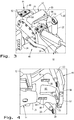
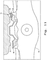
- Figs. 1 and 2 there is shown a portion of an embodiment of an off-road vehicle 10.
- the off-road vehicle 10 is configured as an agricultural tractor, but can be differently configured depending on the application.
- Tractor 10 generally includes an oil sump 12, a suspension arm 14, an axle carriage 16, an axle assembly 18, and a pair of suspension cylinders 20.
- Oil sump 12 is typically part of and located at the bottom of an internal combustion (IC) engine which defines the prime mover for the tractor 10.
- IC internal combustion
- the IC engine is usually a diesel engine, but can be a different type of engine such as a gasoline or liquid propane (LP) engine.
- LP liquid propane
- the cast body of the IC engine also defines part of the chassis of the tractor 10.
- the chassis it is also possible for the chassis to include separate frame members to which the engine is mounted.
- the oil sump 12 is a casting which defines part of the chassis of the tractor 10.
- the suspension arm 14 includes a number of rear pivot arms 22 which are pivotally connected to the chassis of the tractor 10. In the illustrated embodiment, the rear pivot arms 22 are pivotally connected to the oil sump 12, as shown in Fig. 2 .
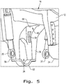
- the front end of the suspension arm 14 has a circular housing 24 which fits around the input coupler 26 of the axle assembly 18.
- the input coupler 26 can be coupled with the drive shaft 28 for the MFD of the axle assembly 18.
- the circular housing 24 can also pivot a limited extent relative to the input coupler 26.
- the axle carriage 16 is mounted to the front end of the oil sump 12. Like the oil sump 12 described above, the axle carriage 16 can be attached to or form part of the chassis of the tractor 10. In the illustrated embodiment, the axle carriage 16 is formed from a heavy casting which is part of the chassis of the tractor 10.
- the axle assembly 18 includes a rigid axle 30 and a pair of wheel hubs 32 mounted at each outboard end of the rigid axle 30. Wheels (not shown) are typically mounted to the hubs 32 in known manner.
- the axle assembly 18 also includes a pivot member 34 which is located approximately midway between the wheel hubs 32 and extends in a forward direction from the front of the rigid axle 18.
- the pivot member 34 can be in the form of a cylindrical member, as shown, and has a longitudinal axis 36 which extends in a fore-to-aft direction of the tractor 10 through the center of the input coupler 26.
- the pivot member 34 is positioned and movable within a generally vertically arranged slot 38 formed in the forward end of the axle carriage 16.
- the pair of suspension cylinders 20 are each connected between the axle carriage 16 and the rigid axle 30.
- the suspension cylinders 20 are positioned on opposite lateral sides of the pivot member 34.
- the suspension cylinders 20 can be located elsewhere, such as behind the rear axle and/or under the axle carriage 20.
- the pair of suspension cylinders 20 are operable to move the rigid axle 30 in vertical directions relative to the axle carriage 16 using a controller (not shown).
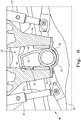
- a suspension system 40 includes the axle carriage 16, axle 30, suspension cylinders 20 and two pairs of roll angle stops 42 and 44 between the axle carriage 16 and axle 30. More particularly, the axle 30 includes a first pair of roll angle stops 42 which engage the axle carriage 16 when the axle 30 is at or near a compressed or fully lowered position relative to the axle carriage 16, and the axle 30 includes a second pair of roll angle stops 44 which engage the axle carriage 16 when the axle 30 is at or near an extended or fully raised position relative to the axle carriage 16.
- the first pair of roll angle stops 42 each include a generally vertically arranged stop surface 46
- the second pair of roll angle stops 44 each include a generally horizontally arranged stop surface 48.
- the axle 30 includes an upwardly extending block 50 with a pair of opposed side surfaces respectively defining the generally vertically arranged stop surfaces 46.
- the vertically arranged stop surfaces 46 can be generally perpendicular to the longitudinal axis of the axle 30, as shown, and thus substantially vertical when the axle 30 is positioned horizontally. Alternatively, the vertically arranged stop surfaces 46 can be at some predetermined angle less than 90° relative to the longitudinal axis of the axle 30 (e.g., 80°-90°).
- the second pair of roll angle stops 44 defined by the generally horizontally arranged stop surfaces 48 are positioned on each lateral side of the block 50.
- the second pair of roll angle stops 44 each include a plate 52 mounted to a top of the axle 30, with each plate 52 having an upper surface defining the generally horizontally arranged stop surface 48.
- the generally horizontally arranged stop surface 48 of each plate 52 is positioned at a predetermined angle relative to horizontal.
- the generally horizontally arranged stop surface 48 is at a slight acute angle relative to a horizontal reference plane (e.g., 1 to 10°).
- the generally horizontally arranged stop surface 48 can be parallel to the longitudinal axis of the axle 30 (i.e., horizontal).
- the plates 52 can be removably attached to the axle 30 using any suitable fastening technique, such as by using fasteners 54 which pass through holes formed in plate 52 and are threaded into the top surface of the axle 30.
- the use of removable plates 52 allows the use of plates with different physical geometries, depending on the application.
- the plates 52 can also be non-removably attached to the top of the axle 30, such as by welding the plates 52 to the axle 30.
- the axle carriage 16 includes a pair of downwardly extending legs 56 at the forward end thereof which define the slot 38. Each leg 56 has a laterally inside surface defining a mating stop surface 58 which is engageable with a corresponding vertically arranged stop surface 46 on the block 50, as will be described below.
- the axle carriage 16 also includes an upwardly extending recess 60 between and rearward of the legs 56.
- the block 50 fits within the recess 60 when the axle 30 is in the fully raised position relative to the axle carriage 16.
- a cover plate 62 is fastened to the bottom end of the legs 56 and defines a stop limit when the axle 30 is at a fully lowered position relative to the axle carriage 16. In particular, when the pivot member 34 contacts the cover plate 62 the axle is at the fully lowered position.
- the axle carriage 16 also includes a pair of bosses 64 formed at the bottom thereof which define a pair of mating stop surfaces 66 which are engageable with a corresponding horizontally arranged stop surface 48 on the axle 30, as will be described below.
- the thickened area of the bosses 64 helps with loading when the horizontal stop surfaces 48 contact the bottom of the axle carriage 16.
- such a thickened area or boss may not be necessary, depending on the construction of the axle carriage 16, and the horizontal stop surfaces 48 may directly contact the axle carriage 16 without such a boss or reinforced area.
- plates similar to the plates 52 can be attached to the bottom side of the axle carriage 16 at the places of contact with the plates 52.
- the various components acting together to limit the roll angle of the axle 30 relative to the axle carriage 16 are collectively referred to as a roll angle stop arrangement of the present invention.
- Such components can include the first pair of roll angle stops 42, the second pair of roll angle stops 44, the mating stop surfaces 58, the pivot member 34, the vertically arranged slot 38, and the mating stop surfaces 66. These various components work together to define the roll angle stop arrangement.
- the exterior shape of the axle 30 and axle carriage 16 also affect the size and shape of the other components making up the roll angle stop arrangement.
- the first pair of roll angle stops 42 engage the axle carriage 16 when the axle 30 is within a first predetermined range of movement relative to the axle carriage 16, and the second pair of roll angle stops 44 engage the axle carriage 16 when the axle 30 is within a second predetermined range of movement relative to the axle carriage 16.
- the first predetermined range of movement is adjacent to the fully lowered position (i.e., in the lower region of the stroke length of the suspension cylinders 20), and the second predetermined range of movement is adjacent to the fully raised position (i.e., in the upper region of the stroke length of the suspension cylinders 20).
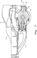
- the axle 30 is shown in a fully lowered position relative to the axle carriage 16, with the pivot member 34 against the cover plate 62.
- the pivot member 34 is movable an overall stroke length of approximately 110 mm, with a neutral position in the middle and a 55 mm stroke length above and below the neutral position.
- a vertically arranged stop surface 46 on the side of block 50 contacts a corresponding mating stop surface 58 on the side of a leg 56 when the axle 30 is at approximately an 8.3° roll angle relative to a horizontal reference.
- the contact area 68 between the vertically arranged stop surface 46 and the corresponding mating stop surface 58 is shown in Fig. 6 .
- the axle 30 is shown in a neutral position approximately midway between the upper and lower maximum positions.
- the vertically arranged stop surface 46 on the side of block 50 still contacts a corresponding mating stop surface 58 on the side of the legs 56 when the axle 30 is at approximately an 8° roll angle relative to a horizontal reference.
- the contact area 68 between the vertically arranged stop surface 46 and the corresponding mating stop surface 58 is shown in Fig. 8 .
- the axle 30 is shown at the transition point where both the vertical stop surface 46 and the horizontal stop surface 48 contact the axle carriage 16 when the axle 32 reaches a maximum roll angle of approximately 7.25° relative to a horizontal reference.
- the contact area 68 between the vertically arranged stop surface 46 and the corresponding mating stop surface 58, and the contact area 70 between the horizontally arranged stop surface 48 and the corresponding mating stop surface 66, are each shown in Fig. 10 .
- transition point between the vertical stop surface 46 and a horizontal stop surface 48 occurs when the axle is at a stroke length of approximately 37 mm above the neutral position.
- the particular transition point between the vertical stop surface 46 and a horizontal stop surface 48 can vary depending on the design and configuration of the first and second pair of roll angle stops 42 and 44 and/or the corresponding mating stop surfaces 58 and 66.
- the axle 30 is shown in a fully raised position relative to the axle carriage 16.
- a horizontally arranged stop surface 48 on the top of the axle 30 contacts a corresponding mating stop surface 66 on the bottom of the axle carriage 16 when the axle 30 is at approximately a 3° roll angle relative to a horizontal reference.
- the contact area 70 between the horizontally arranged stop surface 48 and the corresponding mating stop surface 66 is shown in Fig. 11 .
- the maximum allowed roll angle is only 3° in the illustrated embodiment to prevent the wheel assembly from contacting the chassis, sheet metal or other component of the tractor 10.
- the particular maximum allowed roll angle when the axle is at the fully raised position can of course vary depending on the configuration.
- the axle 30 As the axle 30 moves up and down relative to the axle carriage 16, the axle 30 has a maximum roll angle which varies according to a first mathematical relationship when the axle 30 is at any position within the first predetermined range of movement, and the axle has a roll angle which varies according to a second mathematical relationship when the axle 30 is at any position within the second predetermined range of movement.
- the physical geometry of the first pair of roll angle stops 42 establishes the first mathematical relationship
- the physical geometry of the second pair of roll angle stops 44 and/or plates 52 establish the second mathematical relationship.
- the maximum roll angle is defined as the point at which one of the vertically arranged stop surfaces 46 and/or horizontally arranged stop surfaces 48 contacts the axle carriage 16, thereby stopping further pivoting movement of the axle 30 relative to the axle carriage 16.
- the first predetermined range of movement corresponds to the range of movement when the first pair of roll angle stops 42 establish the maximum allowed roll angle
- the second predetermined range of movement corresponds to a range of movement when the second pair of roll angle stops 44 establish the maximum allowed roll angle.
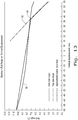
- the line 80 representing the first mathematical relationship during the first predetermined range of movement has a very slight curve, but can be thought of as being a generally linear relationship.
- the line 82 representing the second mathematical relationship during the second predetermined range of movement also has a very slight curve, but can likewise be thought of as being a generally linear relationship.
- the line representing the second mathematical relationship to the right of the intersection point 84 has a steeper slope than the line representing the first mathematical relationship to the left of the intersection point 84.
- the axle 30 has a smallest maximum roll angle when the axle 30 is at the fully raised position (to the right of the graph), and the axle 30 has a greatest maximum roll angle when the axle is at the fully lowered position (to the left of the graph).
- the dashed line represents the linear approximate overall axle stop using each of the first and second pair of roll angle stops 42 and 44.
Landscapes
- Engineering & Computer Science (AREA)
- Mechanical Engineering (AREA)
- Vehicle Body Suspensions (AREA)
Claims (15)
- Geländefahrzeug (10) mit:einem Fahrgestell (12);einem Achsgestell (16), das an dem Fahrgestell (12) befestigt ist oder einen Teil des Fahrgestells (12) bildet;einer Starrachse (30), die an dem Achsgestell (16) befestigt ist, mit einer Radnabe (32) an jedem Ende, wobei die Achse (30) relativ zum Achsgestell (16) vertikal bewegbar ist; undeinem Paar von Federungszylindern (20), wobei jeder Federungszylinder (20) zwischen dem Achsgestell (16) und der Achse (30) angebracht ist, wobei das Paar von Federungszylindern (20) betätigbar ist, um die Achse (30) in vertikale Richtungen relativ zu dem Achsgestell (16) zu bewegen;dadurch gekennzeichnet, dass:
die Achse (30) ein erstes Paar von Rollwinkelanschlägen (42) aufweist, die mit dem Achsgestell (16) eingreifen, wenn sich die Achse (30) in oder nahe einer vollständig abgesenkten Stellung relativ zum Achsgestell (16) befindet, und die Achse (30) ein zweites Paar von Rollwinkelanschlägen (44) aufweist, die mit dem Achsgestell (16) eingreifen, wenn sich die Achse (30) in oder nahe einer vollständig angehobenen Stellung relativ zum Achsgestell (16) befindet. - Geländefahrzeug (10) nach Anspruch 1, wobei das erste Paar von Rollwinkelanschlägen (42) jeweils eine im Wesentlichen vertikal angeordnete Anschlagsfläche (46) aufweist und das zweite Paar von Rollwinkelanschlägen (44) jeweils eine im Wesentlichen horizontal angeordnete Anschlagsfläche (48) aufweist.
- Geländefahrzeug (10) nach Anspruch 2, wobei das Achsgestell (16) eine im Wesentlichen vertikal angeordnete Aussparung (38) aufweist und die Achse (30) ein im Wesentlichen zylindrisches Schwenkelement (34) aufweist, das in etwa mittig zwischen den Enden der Achse (30) angeordnet ist und eine Längsachse (36) aufweist, die sich im Wesentlichen in einer Längsrichtung des Geländefahrzeugs (10) erstreckt, wobei das Schwenkelement (34) innerhalb der Aussparung (38) des Achsgestells (16) angeordnet und vertikal bewegbar ist.
- Geländefahrzeug (10) nach Anspruch 3, wobei das Achsgestell (16) ein Paar von sich nach unten erstreckenden Schenkeln (56) aufweist, die die Aussparung (38) definieren, und die Achse (30) einen sich nach oben erstreckenden Block (50) mit einem Paar von gegenüberliegenden Seitenflächen aufweist, die jeweils die im Wesentlichen vertikal angeordneten Anschlagsflächen (46) definieren, wobei jede der im Wesentlichen vertikal angeordneten Anschlagsflächen (46) mit einem entsprechenden Schenkel (56) eingreifen kann.
- Geländefahrzeug (10) nach Anspruch 4, wobei das Achsgestell (16) eine sich nach oben erstreckende Ausnehmung (60) zwischen den Schenkeln (56) aufweist und der Block (50) in die Ausnehmung (60) passt, wenn sich die Achse (30) in der vollständig angehobenen Stellung befindet.
- Geländefahrzeug (10) nach Anspruch 4, wobei das Paar von im Wesentlichen horizontal angeordneten Anschlagsflächen (48) auf jeweils einer Seite des Blocks (50) angeordnet ist.
- Geländefahrzeug (10) nach Anspruch 6, wobei das zweite Paar von Rollwinkelanschlägen (44) jeweils eine Platte (52) aufweist, die auf einer Oberseite der Achse (30) befestigt ist, wobei jede Platte (52) eine obere Oberfläche aufweist, die die im Wesentlichen horizontal angeordnete Anschlagsfläche (48) definiert.
- Geländefahrzeug (10) nach Anspruch 7, wobei die obere Oberfläche jeder Platte (50) in einem vorbestimmten Winkel relativ zur Horizontalen angeordnet ist.
- Geländefahrzeug (10) nach Anspruch 1, wobei das erste Paar von Rollwinkelanschlägen (42) mit dem Achsgestell (16) eingreift, wenn sich die Achse (30) innerhalb eines ersten vorbestimmten Bewegungsbereichs relativ zum Achsgestell (16) befindet, und das zweite Paar von Rollwinkelanschlägen (44) mit dem Achsgestell (16) eingreift, wenn sich die Achse (30) innerhalb eines zweiten vorbestimmten Bewegungsbereichs relativ zum Achsgestell (16) befindet.
- Geländefahrzeug (10) nach Anspruch 9, wobei der erste vorbestimmte Bewegungsbereich an die vollständig abgesenkte Stellung angrenzt und der zweite vorbestimmte Bewegungsbereich an die vollständig angehobene Stellung angrenzt.
- Geländefahrzeug (10) nach Anspruch 9, wobei die Achse (30) einen maximalen Rollwinkel aufweist, der entsprechend einer ersten mathematischen Beziehung variiert, wenn sich die Achse (30) in irgendeiner Stellung innerhalb des ersten vorbestimmten Bewegungsbereichs befindet, und wobei die Achse (30) einen maximalen Rollwinkel aufweist, der entsprechend einer zweiten mathematischen Beziehung variiert, wenn sich die Achse (30) in irgendeiner Position innerhalb des zweiten vorbestimmten Bewegungsbereichs befindet.
- Geländefahrzeug (10) nach Anspruch 11, wobei die erste mathematische Beziehung und die zweite mathematische Beziehung jeweils im Wesentlichen lineare Beziehungen sind, wobei die zweite mathematische Beziehung eine steilere Steigung als die erste mathematische Beziehung aufweist.
- Geländefahrzeug (10) nach Anspruch 12, wobei ein eindeutiger Kreuzungspunkt (84) zwischen der ersten mathematischen Beziehung und der zweiten mathematischen Beziehung existiert.
- Geländefahrzeug (10) nach Anspruch 11, wobei die Achse (30) einen kleinsten Rollwinkel aufweist, wenn sich die Achse (30) in der vollständig angehobenen Stellung befindet, und die Achse einen größten Rollwinkel aufweist, wenn sich die Achse (30) in der vollständig abgesenkten Position befindet.
- Geländefahrzeug (10) nach Anspruch 1, wobei sich die Achse (30) in der vollständig abgesenkten Stellung befindet, wenn das Schwenkelement (34) an die Unterseite der Aussparung (38) angelegt ist.
Applications Claiming Priority (2)
| Application Number | Priority Date | Filing Date | Title |
|---|---|---|---|
| ITMO20140098 | 2014-04-09 | ||
| PCT/EP2015/057636 WO2015155251A1 (en) | 2014-04-09 | 2015-04-08 | Roll angle stop arrangement for a suspension system in an off-road vehicle |
Publications (2)
| Publication Number | Publication Date |
|---|---|
| EP3129246A1 EP3129246A1 (de) | 2017-02-15 |
| EP3129246B1 true EP3129246B1 (de) | 2018-06-20 |
Family
ID=50877579
Family Applications (1)
| Application Number | Title | Priority Date | Filing Date |
|---|---|---|---|
| EP15713922.1A Active EP3129246B1 (de) | 2014-04-09 | 2015-04-08 | Rollwinkelstoppanordnung für ein aufhängungssystem in einem geländefahrzeug |
Country Status (5)
| Country | Link |
|---|---|
| US (1) | US10035394B2 (de) |
| EP (1) | EP3129246B1 (de) |
| CN (1) | CN106457944B (de) |
| BR (1) | BR112016023626B1 (de) |
| WO (1) | WO2015155251A1 (de) |
Families Citing this family (4)
| Publication number | Priority date | Publication date | Assignee | Title |
|---|---|---|---|---|
| BR112020005397B1 (pt) * | 2017-09-23 | 2024-01-23 | Hendrickson Usa, L.L.C | Montagem de assentos de eixo mecânico e método de produção de uma montagem de assentos de eixo mecânico |
| IT201700113851A1 (it) * | 2017-10-10 | 2019-04-10 | Carraro Spa | Gruppo sospensione per assale di un veicolo |
| US11679626B2 (en) * | 2019-04-17 | 2023-06-20 | Artec Industries, LLC | Apex axle truss system |
| US11292311B2 (en) * | 2019-10-25 | 2022-04-05 | Caterpillar Inc. | Space frame front upper suspension connection |
Family Cites Families (19)
| Publication number | Priority date | Publication date | Assignee | Title |
|---|---|---|---|---|
| DE3901757A1 (de) * | 1988-01-29 | 1989-08-10 | Zahnradfabrik Friedrichshafen | Aufhaengung einer starrachse eines schleppers |
| US5322310A (en) * | 1992-12-24 | 1994-06-21 | Ford New Holland, Inc. | Variable oscillation stops for tractors with compound steering mechanism |
| US5447321A (en) * | 1994-07-08 | 1995-09-05 | New Holland North America, Inc. | Oscillation stop mechanism for compact tractors |
| IT1287898B1 (it) | 1996-05-14 | 1998-08-26 | Carraro Spa | Sistema di molleggio e variabilita' di assetto di un ponte differenziale |
| DE19643263C2 (de) | 1996-10-19 | 2002-06-20 | Deere & Co | Pendelnd gelagerte, gefederte Achsaufhängung |
| IT1291750B1 (it) | 1997-05-16 | 1999-01-21 | Clark Hurth Components Spa | Struttura di sospensione elastica per assali di veicoli industriali e simili |
| US6857840B2 (en) * | 2000-01-28 | 2005-02-22 | Simpson Tranzformer | Removable load bed for a vehicle |
| US6502840B1 (en) | 2001-10-12 | 2003-01-07 | Deere & Company | Suspended axle with side and oscillation control linkage |
| US7377522B2 (en) * | 2002-09-18 | 2008-05-27 | Macisaac William L | Vehicle with movable and inwardly tilting safety body |
| WO2004030954A2 (en) | 2002-10-02 | 2004-04-15 | Dana Corporation | Steer axle suspension |
| US7585032B2 (en) * | 2003-10-17 | 2009-09-08 | American Axle & Manufacturing, Inc. | Modular axle assembly |
| US7559403B2 (en) | 2006-04-05 | 2009-07-14 | Schmitz Geoffrey W | Modular, central frame, offset, dual control arm independent suspension and suspension retrofit |
| GB2440322B (en) * | 2006-07-25 | 2011-07-06 | Advanced Vehicle Concepts Ltd | Wheeled vehicle |
| US7721832B2 (en) | 2007-08-01 | 2010-05-25 | Deere & Company | Walking beam suspension |
| CN201128363Y (zh) * | 2007-12-17 | 2008-10-08 | 浙江杭叉工程机械股份有限公司 | 驱动桥悬挂系统 |
| CN201148109Y (zh) * | 2007-12-19 | 2008-11-12 | 高永升 | 直联式拖拉机前桥托架 |
| US8280590B2 (en) * | 2010-05-24 | 2012-10-02 | Deere & Company | Automatically adjustable axle oscillation stops |
| CN202022071U (zh) * | 2011-05-12 | 2011-11-02 | 南京农业大学 | 拖拉机双横臂前悬架装置 |
| CA2875251A1 (en) * | 2013-12-18 | 2015-06-18 | Dallas Smith Corp. | Suspension for a multiple height vehicle |
-
2015
- 2015-04-08 WO PCT/EP2015/057636 patent/WO2015155251A1/en not_active Ceased
- 2015-04-08 BR BR112016023626-2A patent/BR112016023626B1/pt active IP Right Grant
- 2015-04-08 EP EP15713922.1A patent/EP3129246B1/de active Active
- 2015-04-08 US US15/301,909 patent/US10035394B2/en active Active
- 2015-04-08 CN CN201580026519.XA patent/CN106457944B/zh not_active Expired - Fee Related
Non-Patent Citations (1)
| Title |
|---|
| None * |
Also Published As
| Publication number | Publication date |
|---|---|
| BR112016023626A2 (pt) | 2017-08-15 |
| EP3129246A1 (de) | 2017-02-15 |
| BR112016023626B1 (pt) | 2022-04-05 |
| US20170120706A1 (en) | 2017-05-04 |
| WO2015155251A1 (en) | 2015-10-15 |
| CN106457944A (zh) | 2017-02-22 |
| CN106457944B (zh) | 2019-05-03 |
| US10035394B2 (en) | 2018-07-31 |
Similar Documents
| Publication | Publication Date | Title |
|---|---|---|
| US7644942B2 (en) | Active axle suspension system | |
| US7510198B2 (en) | Axle suspension system | |
| JP3321047B2 (ja) | 枢動可能なばね取り付け車軸懸架装置 | |
| EP3129246B1 (de) | Rollwinkelstoppanordnung für ein aufhängungssystem in einem geländefahrzeug | |
| US10513291B2 (en) | Automatic tilting vehicle | |
| JPH06245621A (ja) | 乗用芝刈機 | |
| EP2938530B1 (de) | Zwischenlenkungsarm | |
| US20180334001A1 (en) | Suspension device for non-steered driving wheel incorporating in-wheel motor | |
| EP3541688B1 (de) | Raupenfahrzeug mit einem drehbar angebrachten drehgestell | |
| AU2022402874B2 (en) | Suspension system, engineering vehicle, and control method of suspension system | |
| EP1972471B1 (de) | Aktives Achsenaufhängungssystem | |
| RU2487018C2 (ru) | Система стабилизатора для подвески моста и стабилизатор | |
| US7195260B2 (en) | Steer axle suspension | |
| JP6016458B2 (ja) | 作業車両の懸架装置 | |
| EP3548318B1 (de) | Verfahren zur steuerung der radachsenaufhängung eines fahrzeugs | |
| US20170203623A1 (en) | Wheel suspension device | |
| KR20130056642A (ko) | 스테빌라이져 바 링크의 가변조절장치 | |
| EP2058439A2 (de) | Gelenkfahrzeug | |
| EP3266683B1 (de) | Chassis für selbstangetriebene arbeitsmaschinen | |
| KR20160076669A (ko) | 4륜식 지게차의 스티어 액슬 구조 | |
| US20230347973A1 (en) | Agricultural high-clearance vehicle with improved steering and suspension coupling | |
| JP7415229B2 (ja) | 乗用作業機 | |
| JP4965501B2 (ja) | 走行車両のサスペンション装置 | |
| CN208344328U (zh) | 左转向臂 | |
| US10391827B2 (en) | Wheel suspension for the rear axle of a vehicle |
Legal Events
| Date | Code | Title | Description |
|---|---|---|---|
| STAA | Information on the status of an ep patent application or granted ep patent |
Free format text: STATUS: THE INTERNATIONAL PUBLICATION HAS BEEN MADE |
|
| PUAI | Public reference made under article 153(3) epc to a published international application that has entered the european phase |
Free format text: ORIGINAL CODE: 0009012 |
|
| STAA | Information on the status of an ep patent application or granted ep patent |
Free format text: STATUS: REQUEST FOR EXAMINATION WAS MADE |
|
| 17P | Request for examination filed |
Effective date: 20161109 |
|
| AK | Designated contracting states |
Kind code of ref document: A1 Designated state(s): AL AT BE BG CH CY CZ DE DK EE ES FI FR GB GR HR HU IE IS IT LI LT LU LV MC MK MT NL NO PL PT RO RS SE SI SK SM TR |
|
| AX | Request for extension of the european patent |
Extension state: BA ME |
|
| DAV | Request for validation of the european patent (deleted) | ||
| DAX | Request for extension of the european patent (deleted) | ||
| REG | Reference to a national code |
Ref country code: DE Ref legal event code: R079 Ref document number: 602015012506 Country of ref document: DE Free format text: PREVIOUS MAIN CLASS: B60G0009020000 Ipc: B60G0021050000 |
|
| RIC1 | Information provided on ipc code assigned before grant |
Ipc: B60G 13/06 20060101ALI20171124BHEP Ipc: B60G 21/05 20060101AFI20171124BHEP Ipc: B60G 9/02 20060101ALI20171124BHEP |
|
| GRAP | Despatch of communication of intention to grant a patent |
Free format text: ORIGINAL CODE: EPIDOSNIGR1 |
|
| STAA | Information on the status of an ep patent application or granted ep patent |
Free format text: STATUS: GRANT OF PATENT IS INTENDED |
|
| INTG | Intention to grant announced |
Effective date: 20180115 |
|
| RIN1 | Information on inventor provided before grant (corrected) |
Inventor name: VESCOVINI, MAURIZIO |
|
| GRAS | Grant fee paid |
Free format text: ORIGINAL CODE: EPIDOSNIGR3 |
|
| GRAA | (expected) grant |
Free format text: ORIGINAL CODE: 0009210 |
|
| STAA | Information on the status of an ep patent application or granted ep patent |
Free format text: STATUS: THE PATENT HAS BEEN GRANTED |
|
| AK | Designated contracting states |
Kind code of ref document: B1 Designated state(s): AL AT BE BG CH CY CZ DE DK EE ES FI FR GB GR HR HU IE IS IT LI LT LU LV MC MK MT NL NO PL PT RO RS SE SI SK SM TR |
|
| REG | Reference to a national code |
Ref country code: GB Ref legal event code: FG4D |
|
| REG | Reference to a national code |
Ref country code: IE Ref legal event code: FG4D |
|
| REG | Reference to a national code |
Ref country code: AT Ref legal event code: REF Ref document number: 1010321 Country of ref document: AT Kind code of ref document: T Effective date: 20180715 |
|
| REG | Reference to a national code |
Ref country code: DE Ref legal event code: R096 Ref document number: 602015012506 Country of ref document: DE |
|
| REG | Reference to a national code |
Ref country code: NL Ref legal event code: MP Effective date: 20180620 |
|
| PG25 | Lapsed in a contracting state [announced via postgrant information from national office to epo] |
Ref country code: SE Free format text: LAPSE BECAUSE OF FAILURE TO SUBMIT A TRANSLATION OF THE DESCRIPTION OR TO PAY THE FEE WITHIN THE PRESCRIBED TIME-LIMIT Effective date: 20180620 Ref country code: NO Free format text: LAPSE BECAUSE OF FAILURE TO SUBMIT A TRANSLATION OF THE DESCRIPTION OR TO PAY THE FEE WITHIN THE PRESCRIBED TIME-LIMIT Effective date: 20180920 Ref country code: FI Free format text: LAPSE BECAUSE OF FAILURE TO SUBMIT A TRANSLATION OF THE DESCRIPTION OR TO PAY THE FEE WITHIN THE PRESCRIBED TIME-LIMIT Effective date: 20180620 Ref country code: BG Free format text: LAPSE BECAUSE OF FAILURE TO SUBMIT A TRANSLATION OF THE DESCRIPTION OR TO PAY THE FEE WITHIN THE PRESCRIBED TIME-LIMIT Effective date: 20180920 Ref country code: LT Free format text: LAPSE BECAUSE OF FAILURE TO SUBMIT A TRANSLATION OF THE DESCRIPTION OR TO PAY THE FEE WITHIN THE PRESCRIBED TIME-LIMIT Effective date: 20180620 |
|
| REG | Reference to a national code |
Ref country code: LT Ref legal event code: MG4D |
|
| PG25 | Lapsed in a contracting state [announced via postgrant information from national office to epo] |
Ref country code: RS Free format text: LAPSE BECAUSE OF FAILURE TO SUBMIT A TRANSLATION OF THE DESCRIPTION OR TO PAY THE FEE WITHIN THE PRESCRIBED TIME-LIMIT Effective date: 20180620 Ref country code: HR Free format text: LAPSE BECAUSE OF FAILURE TO SUBMIT A TRANSLATION OF THE DESCRIPTION OR TO PAY THE FEE WITHIN THE PRESCRIBED TIME-LIMIT Effective date: 20180620 Ref country code: GR Free format text: LAPSE BECAUSE OF FAILURE TO SUBMIT A TRANSLATION OF THE DESCRIPTION OR TO PAY THE FEE WITHIN THE PRESCRIBED TIME-LIMIT Effective date: 20180921 Ref country code: LV Free format text: LAPSE BECAUSE OF FAILURE TO SUBMIT A TRANSLATION OF THE DESCRIPTION OR TO PAY THE FEE WITHIN THE PRESCRIBED TIME-LIMIT Effective date: 20180620 |
|
| REG | Reference to a national code |
Ref country code: AT Ref legal event code: MK05 Ref document number: 1010321 Country of ref document: AT Kind code of ref document: T Effective date: 20180620 |
|
| PG25 | Lapsed in a contracting state [announced via postgrant information from national office to epo] |
Ref country code: NL Free format text: LAPSE BECAUSE OF FAILURE TO SUBMIT A TRANSLATION OF THE DESCRIPTION OR TO PAY THE FEE WITHIN THE PRESCRIBED TIME-LIMIT Effective date: 20180620 |
|
| PG25 | Lapsed in a contracting state [announced via postgrant information from national office to epo] |
Ref country code: CZ Free format text: LAPSE BECAUSE OF FAILURE TO SUBMIT A TRANSLATION OF THE DESCRIPTION OR TO PAY THE FEE WITHIN THE PRESCRIBED TIME-LIMIT Effective date: 20180620 Ref country code: RO Free format text: LAPSE BECAUSE OF FAILURE TO SUBMIT A TRANSLATION OF THE DESCRIPTION OR TO PAY THE FEE WITHIN THE PRESCRIBED TIME-LIMIT Effective date: 20180620 Ref country code: AT Free format text: LAPSE BECAUSE OF FAILURE TO SUBMIT A TRANSLATION OF THE DESCRIPTION OR TO PAY THE FEE WITHIN THE PRESCRIBED TIME-LIMIT Effective date: 20180620 Ref country code: IS Free format text: LAPSE BECAUSE OF FAILURE TO SUBMIT A TRANSLATION OF THE DESCRIPTION OR TO PAY THE FEE WITHIN THE PRESCRIBED TIME-LIMIT Effective date: 20181020 Ref country code: EE Free format text: LAPSE BECAUSE OF FAILURE TO SUBMIT A TRANSLATION OF THE DESCRIPTION OR TO PAY THE FEE WITHIN THE PRESCRIBED TIME-LIMIT Effective date: 20180620 Ref country code: SK Free format text: LAPSE BECAUSE OF FAILURE TO SUBMIT A TRANSLATION OF THE DESCRIPTION OR TO PAY THE FEE WITHIN THE PRESCRIBED TIME-LIMIT Effective date: 20180620 Ref country code: PL Free format text: LAPSE BECAUSE OF FAILURE TO SUBMIT A TRANSLATION OF THE DESCRIPTION OR TO PAY THE FEE WITHIN THE PRESCRIBED TIME-LIMIT Effective date: 20180620 |
|
| PG25 | Lapsed in a contracting state [announced via postgrant information from national office to epo] |
Ref country code: IT Free format text: LAPSE BECAUSE OF FAILURE TO SUBMIT A TRANSLATION OF THE DESCRIPTION OR TO PAY THE FEE WITHIN THE PRESCRIBED TIME-LIMIT Effective date: 20180620 Ref country code: SM Free format text: LAPSE BECAUSE OF FAILURE TO SUBMIT A TRANSLATION OF THE DESCRIPTION OR TO PAY THE FEE WITHIN THE PRESCRIBED TIME-LIMIT Effective date: 20180620 Ref country code: ES Free format text: LAPSE BECAUSE OF FAILURE TO SUBMIT A TRANSLATION OF THE DESCRIPTION OR TO PAY THE FEE WITHIN THE PRESCRIBED TIME-LIMIT Effective date: 20180620 |
|
| REG | Reference to a national code |
Ref country code: DE Ref legal event code: R097 Ref document number: 602015012506 Country of ref document: DE |
|
| PLBE | No opposition filed within time limit |
Free format text: ORIGINAL CODE: 0009261 |
|
| STAA | Information on the status of an ep patent application or granted ep patent |
Free format text: STATUS: NO OPPOSITION FILED WITHIN TIME LIMIT |
|
| 26N | No opposition filed |
Effective date: 20190321 |
|
| PG25 | Lapsed in a contracting state [announced via postgrant information from national office to epo] |
Ref country code: DK Free format text: LAPSE BECAUSE OF FAILURE TO SUBMIT A TRANSLATION OF THE DESCRIPTION OR TO PAY THE FEE WITHIN THE PRESCRIBED TIME-LIMIT Effective date: 20180620 |
|
| PG25 | Lapsed in a contracting state [announced via postgrant information from national office to epo] |
Ref country code: SI Free format text: LAPSE BECAUSE OF FAILURE TO SUBMIT A TRANSLATION OF THE DESCRIPTION OR TO PAY THE FEE WITHIN THE PRESCRIBED TIME-LIMIT Effective date: 20180620 |
|
| PG25 | Lapsed in a contracting state [announced via postgrant information from national office to epo] |
Ref country code: AL Free format text: LAPSE BECAUSE OF FAILURE TO SUBMIT A TRANSLATION OF THE DESCRIPTION OR TO PAY THE FEE WITHIN THE PRESCRIBED TIME-LIMIT Effective date: 20180620 |
|
| REG | Reference to a national code |
Ref country code: CH Ref legal event code: PL |
|
| REG | Reference to a national code |
Ref country code: BE Ref legal event code: MM Effective date: 20190430 |
|
| PG25 | Lapsed in a contracting state [announced via postgrant information from national office to epo] |
Ref country code: LU Free format text: LAPSE BECAUSE OF NON-PAYMENT OF DUE FEES Effective date: 20190408 Ref country code: MC Free format text: LAPSE BECAUSE OF FAILURE TO SUBMIT A TRANSLATION OF THE DESCRIPTION OR TO PAY THE FEE WITHIN THE PRESCRIBED TIME-LIMIT Effective date: 20180620 |
|
| PG25 | Lapsed in a contracting state [announced via postgrant information from national office to epo] |
Ref country code: LI Free format text: LAPSE BECAUSE OF NON-PAYMENT OF DUE FEES Effective date: 20190430 Ref country code: CH Free format text: LAPSE BECAUSE OF NON-PAYMENT OF DUE FEES Effective date: 20190430 |
|
| PG25 | Lapsed in a contracting state [announced via postgrant information from national office to epo] |
Ref country code: BE Free format text: LAPSE BECAUSE OF NON-PAYMENT OF DUE FEES Effective date: 20190430 |
|
| PG25 | Lapsed in a contracting state [announced via postgrant information from national office to epo] |
Ref country code: TR Free format text: LAPSE BECAUSE OF FAILURE TO SUBMIT A TRANSLATION OF THE DESCRIPTION OR TO PAY THE FEE WITHIN THE PRESCRIBED TIME-LIMIT Effective date: 20180620 |
|
| PG25 | Lapsed in a contracting state [announced via postgrant information from national office to epo] |
Ref country code: IE Free format text: LAPSE BECAUSE OF NON-PAYMENT OF DUE FEES Effective date: 20190408 |
|
| PG25 | Lapsed in a contracting state [announced via postgrant information from national office to epo] |
Ref country code: PT Free format text: LAPSE BECAUSE OF FAILURE TO SUBMIT A TRANSLATION OF THE DESCRIPTION OR TO PAY THE FEE WITHIN THE PRESCRIBED TIME-LIMIT Effective date: 20181022 |
|
| PG25 | Lapsed in a contracting state [announced via postgrant information from national office to epo] |
Ref country code: CY Free format text: LAPSE BECAUSE OF FAILURE TO SUBMIT A TRANSLATION OF THE DESCRIPTION OR TO PAY THE FEE WITHIN THE PRESCRIBED TIME-LIMIT Effective date: 20180620 |
|
| PG25 | Lapsed in a contracting state [announced via postgrant information from national office to epo] |
Ref country code: MT Free format text: LAPSE BECAUSE OF FAILURE TO SUBMIT A TRANSLATION OF THE DESCRIPTION OR TO PAY THE FEE WITHIN THE PRESCRIBED TIME-LIMIT Effective date: 20180620 Ref country code: HU Free format text: LAPSE BECAUSE OF FAILURE TO SUBMIT A TRANSLATION OF THE DESCRIPTION OR TO PAY THE FEE WITHIN THE PRESCRIBED TIME-LIMIT; INVALID AB INITIO Effective date: 20150408 |
|
| PG25 | Lapsed in a contracting state [announced via postgrant information from national office to epo] |
Ref country code: MK Free format text: LAPSE BECAUSE OF FAILURE TO SUBMIT A TRANSLATION OF THE DESCRIPTION OR TO PAY THE FEE WITHIN THE PRESCRIBED TIME-LIMIT Effective date: 20180620 |
|
| PGFP | Annual fee paid to national office [announced via postgrant information from national office to epo] |
Ref country code: DE Payment date: 20250428 Year of fee payment: 11 |
|
| PGFP | Annual fee paid to national office [announced via postgrant information from national office to epo] |
Ref country code: GB Payment date: 20250422 Year of fee payment: 11 |
|
| PGFP | Annual fee paid to national office [announced via postgrant information from national office to epo] |
Ref country code: FR Payment date: 20250424 Year of fee payment: 11 |