EP3128641A1 - Système de cellules de mémoire et procédé pour agencer un module de cellules - Google Patents
Système de cellules de mémoire et procédé pour agencer un module de cellules Download PDFInfo
- Publication number
- EP3128641A1 EP3128641A1 EP15772298.4A EP15772298A EP3128641A1 EP 3128641 A1 EP3128641 A1 EP 3128641A1 EP 15772298 A EP15772298 A EP 15772298A EP 3128641 A1 EP3128641 A1 EP 3128641A1
- Authority
- EP
- European Patent Office
- Prior art keywords
- battery
- deterioration
- cabinet
- modules
- numbering
- Prior art date
- Legal status (The legal status is an assumption and is not a legal conclusion. Google has not performed a legal analysis and makes no representation as to the accuracy of the status listed.)
- Granted
Links
- 238000000034 method Methods 0.000 title claims abstract description 23
- 210000004027 cell Anatomy 0.000 title 1
- 210000000352 storage cell Anatomy 0.000 title 1
- 230000006866 deterioration Effects 0.000 claims abstract description 63
- 230000008707 rearrangement Effects 0.000 claims abstract description 34
- 238000007599 discharging Methods 0.000 claims abstract description 10
- 230000009467 reduction Effects 0.000 claims description 5
- 230000001174 ascending effect Effects 0.000 claims description 4
- 230000007774 longterm Effects 0.000 abstract description 5
- 230000008859 change Effects 0.000 description 7
- 238000007689 inspection Methods 0.000 description 5
- HBBGRARXTFLTSG-UHFFFAOYSA-N Lithium ion Chemical compound [Li+] HBBGRARXTFLTSG-UHFFFAOYSA-N 0.000 description 4
- 229910001416 lithium ion Inorganic materials 0.000 description 4
- 230000008569 process Effects 0.000 description 4
- 230000007423 decrease Effects 0.000 description 3
- 239000011159 matrix material Substances 0.000 description 3
- 238000010248 power generation Methods 0.000 description 3
- 238000001816 cooling Methods 0.000 description 2
- 238000010586 diagram Methods 0.000 description 2
- 230000000694 effects Effects 0.000 description 2
- 238000004519 manufacturing process Methods 0.000 description 2
- 230000001133 acceleration Effects 0.000 description 1
- 230000003750 conditioning effect Effects 0.000 description 1
- 230000003247 decreasing effect Effects 0.000 description 1
- 230000020169 heat generation Effects 0.000 description 1
- 238000009434 installation Methods 0.000 description 1
- 239000002184 metal Substances 0.000 description 1
- 238000012986 modification Methods 0.000 description 1
- 230000004048 modification Effects 0.000 description 1
- 238000012544 monitoring process Methods 0.000 description 1
- 238000011084 recovery Methods 0.000 description 1
- 230000003068 static effect Effects 0.000 description 1
- 230000001629 suppression Effects 0.000 description 1
Images


Classifications
-
- H—ELECTRICITY
- H01—ELECTRIC ELEMENTS
- H01M—PROCESSES OR MEANS, e.g. BATTERIES, FOR THE DIRECT CONVERSION OF CHEMICAL ENERGY INTO ELECTRICAL ENERGY
- H01M10/00—Secondary cells; Manufacture thereof
- H01M10/42—Methods or arrangements for servicing or maintenance of secondary cells or secondary half-cells
- H01M10/425—Structural combination with electronic components, e.g. electronic circuits integrated to the outside of the casing
-
- G—PHYSICS
- G01—MEASURING; TESTING
- G01R—MEASURING ELECTRIC VARIABLES; MEASURING MAGNETIC VARIABLES
- G01R31/00—Arrangements for testing electric properties; Arrangements for locating electric faults; Arrangements for electrical testing characterised by what is being tested not provided for elsewhere
- G01R31/36—Arrangements for testing, measuring or monitoring the electrical condition of accumulators or electric batteries, e.g. capacity or state of charge [SoC]
- G01R31/392—Determining battery ageing or deterioration, e.g. state of health
-
- H—ELECTRICITY
- H01—ELECTRIC ELEMENTS
- H01M—PROCESSES OR MEANS, e.g. BATTERIES, FOR THE DIRECT CONVERSION OF CHEMICAL ENERGY INTO ELECTRICAL ENERGY
- H01M10/00—Secondary cells; Manufacture thereof
- H01M10/42—Methods or arrangements for servicing or maintenance of secondary cells or secondary half-cells
- H01M10/48—Accumulators combined with arrangements for measuring, testing or indicating the condition of cells, e.g. the level or density of the electrolyte
- H01M10/482—Accumulators combined with arrangements for measuring, testing or indicating the condition of cells, e.g. the level or density of the electrolyte for several batteries or cells simultaneously or sequentially
-
- H—ELECTRICITY
- H01—ELECTRIC ELEMENTS
- H01M—PROCESSES OR MEANS, e.g. BATTERIES, FOR THE DIRECT CONVERSION OF CHEMICAL ENERGY INTO ELECTRICAL ENERGY
- H01M10/00—Secondary cells; Manufacture thereof
- H01M10/42—Methods or arrangements for servicing or maintenance of secondary cells or secondary half-cells
- H01M10/48—Accumulators combined with arrangements for measuring, testing or indicating the condition of cells, e.g. the level or density of the electrolyte
- H01M10/486—Accumulators combined with arrangements for measuring, testing or indicating the condition of cells, e.g. the level or density of the electrolyte for measuring temperature
-
- H—ELECTRICITY
- H01—ELECTRIC ELEMENTS
- H01M—PROCESSES OR MEANS, e.g. BATTERIES, FOR THE DIRECT CONVERSION OF CHEMICAL ENERGY INTO ELECTRICAL ENERGY
- H01M50/00—Constructional details or processes of manufacture of the non-active parts of electrochemical cells other than fuel cells, e.g. hybrid cells
- H01M50/20—Mountings; Secondary casings or frames; Racks, modules or packs; Suspension devices; Shock absorbers; Transport or carrying devices; Holders
- H01M50/204—Racks, modules or packs for multiple batteries or multiple cells
-
- H—ELECTRICITY
- H02—GENERATION; CONVERSION OR DISTRIBUTION OF ELECTRIC POWER
- H02J—CIRCUIT ARRANGEMENTS OR SYSTEMS FOR SUPPLYING OR DISTRIBUTING ELECTRIC POWER; SYSTEMS FOR STORING ELECTRIC ENERGY
- H02J7/00—Circuit arrangements for charging or depolarising batteries or for supplying loads from batteries
- H02J7/0013—Circuit arrangements for charging or depolarising batteries or for supplying loads from batteries acting upon several batteries simultaneously or sequentially
- H02J7/0024—Parallel/serial switching of connection of batteries to charge or load circuit
-
- H—ELECTRICITY
- H02—GENERATION; CONVERSION OR DISTRIBUTION OF ELECTRIC POWER
- H02J—CIRCUIT ARRANGEMENTS OR SYSTEMS FOR SUPPLYING OR DISTRIBUTING ELECTRIC POWER; SYSTEMS FOR STORING ELECTRIC ENERGY
- H02J7/00—Circuit arrangements for charging or depolarising batteries or for supplying loads from batteries
- H02J7/0042—Circuit arrangements for charging or depolarising batteries or for supplying loads from batteries characterised by the mechanical construction
- H02J7/0045—Circuit arrangements for charging or depolarising batteries or for supplying loads from batteries characterised by the mechanical construction concerning the insertion or the connection of the batteries
-
- H—ELECTRICITY
- H01—ELECTRIC ELEMENTS
- H01M—PROCESSES OR MEANS, e.g. BATTERIES, FOR THE DIRECT CONVERSION OF CHEMICAL ENERGY INTO ELECTRICAL ENERGY
- H01M10/00—Secondary cells; Manufacture thereof
- H01M10/42—Methods or arrangements for servicing or maintenance of secondary cells or secondary half-cells
- H01M10/425—Structural combination with electronic components, e.g. electronic circuits integrated to the outside of the casing
- H01M2010/4271—Battery management systems including electronic circuits, e.g. control of current or voltage to keep battery in healthy state, cell balancing
-
- H—ELECTRICITY
- H01—ELECTRIC ELEMENTS
- H01M—PROCESSES OR MEANS, e.g. BATTERIES, FOR THE DIRECT CONVERSION OF CHEMICAL ENERGY INTO ELECTRICAL ENERGY
- H01M2220/00—Batteries for particular applications
- H01M2220/10—Batteries in stationary systems, e.g. emergency power source in plant
-
- Y—GENERAL TAGGING OF NEW TECHNOLOGICAL DEVELOPMENTS; GENERAL TAGGING OF CROSS-SECTIONAL TECHNOLOGIES SPANNING OVER SEVERAL SECTIONS OF THE IPC; TECHNICAL SUBJECTS COVERED BY FORMER USPC CROSS-REFERENCE ART COLLECTIONS [XRACs] AND DIGESTS
- Y02—TECHNOLOGIES OR APPLICATIONS FOR MITIGATION OR ADAPTATION AGAINST CLIMATE CHANGE
- Y02E—REDUCTION OF GREENHOUSE GAS [GHG] EMISSIONS, RELATED TO ENERGY GENERATION, TRANSMISSION OR DISTRIBUTION
- Y02E60/00—Enabling technologies; Technologies with a potential or indirect contribution to GHG emissions mitigation
- Y02E60/10—Energy storage using batteries
Definitions
- Embodiments of the present disclosure relate to a secondary battery system and a method of arranging battery modules which are capable of recovering a system performance, and which are capable of maintaining the system performance in the long term.
- a large-scale secondary battery system including secondary batteries For applications of suppressing a power generation fluctuation which utilizes natural energy like solar light and wind power, suppressing a power demand fluctuation, and peak shifting, the utilization of a large-scale secondary battery system including secondary batteries is expected.
- a large-scale secondary battery system that utilizes lithium-ion batteries which have a remarkably improved performance is becoming available in recent years.
- a long-term operation such as 15 years or 20 years, is expected.
- a cell which is a minimum unit of the secondary battery in single or plurality connected in parallel are connected in series, and may further be connected in parallel.
- a series connection configuration and a parallel connection configuration are typically repeated hierarchically to construct the system.
- the minimum unit replacement will be referred to as a battery module.
- the performance deteriorates over time.
- the deterioration speed of each single cells or the battery modules differ when the utilization condition differs, and even if the same utilization condition is intended, the installment location (e.g., spatial arrangement and arrangement on a circuit) in addition to the individual difference also causes a variability in each strict utilization condition resulting in the variability of deterioration speed.
- the object of the embodiments of the present disclosure is to provide a secondary battery system and a method of arranging battery modules which are capable of recovering a system performance and maintaining the system performance in the long term.
- a secondary battery system includes:
- a method of arranging battery modules executed in the above embodiment is also an embodiment of the present disclosure.
- an explanation will be given with an exemplary secondary battery system that has a plurality of battery modules connected in series, and plurality of them further connected in parallel.
- the deterioration status of each battery module is inspected at an specific timing during the operation of the secondary battery system, and each battery module is re-arranged in accordance with the result. More specifically, all battery modules in the secondary battery system are ranked corresponding to the deterioration progress, and the battery modules sequential to the ranking are re-arranged on the same series connection configuration group, thus accomplishing the recovery of the overall system performance by reducing the deterioration variability in the series connection configuration.
- a configuration of the secondary battery system according to the present embodiment will be explained below.
- FIG. 1 illustrates an entire configuration of a secondary battery system according to the embodiment of the present disclosure.
- a plurality of battery modules 1 are connected in series to form a battery cabinet 2, and the plurality of battery cabinets 2 is connected in parallel to respective positive and negative terminals by wirings (DC) 4, and are connected to the DC terminal of PSC(Power Conditioning System, power converter) 3.
- DC Power Conditioning System
- the AC terminal of the PCS 3 is connected to an unillustrated power system via a wiring (AC) 6.
- the PCS 3 is connected to a battery controller 7 by a signal line to perform charging-discharging control on the group of battery cabinets 2 connected in parallel.
- the battery controller 7 and each battery cabinet 2 are also connected with each other by a signal line for a status monitoring.
- the above battery module 1 is a plurality of cells connected in series or in parallel or in a serial-parallel combination, and is the minimum unit for replacement.
- a wiring resistance 5 is arranged in the cross wiring between the battery cabinets 2, and between the PCS 3 and the battery cabinet 2.
- FIG. 2 illustrates an exemplary physical arrangement of the battery modules in the battery cabinet 2.
- the plurality of battery modules 1 is stacked and arranged in the vertical direction in a metal casing to form the battery cabinet 2.
- forced air cooling such as by a fan is not performed on the battery cabinet 2, but a natural air cooling structure by convection is employed.
- FIG. 3 illustrates the detailed configuration of the battery controller 7.
- the battery controller 7 includes a deterioration inspecting block 11 that performs a deterioration inspection on all battery modules 1, a numbering block 12 that performs a numbering on the battery module 1 in the system in accordance with the deterioration inspection result, and a re-arrangement determining block 13 that determines the re-arrangement location in accordance with the numbering.
- Typical parameters that change in accordance with the deterioration are a capacity and an internal resistance.
- the capacity decreases over time, while the internal resistance increases over time.
- One of the reasons that causes the capacity reduction is an increase of the internal resistance, but a natural capacity deterioration that are not caused by the internal resistance is also present.
- the surrounding temperature of the battery module 1 at the higher position in the vertical direction becomes higher than the surrounding temperature of the battery module 1 at the lower position.
- the deterioration progress (internal resistance increase) of the battery module 1 at the higher position advances faster than the deterioration progress of the battery module 1 at the lower position. Consequently, the Joule heat generated when charging-discharging take place by the battery module 1 at the higher position is greater than that of the battery module 1 at the lower position. Accordingly, the temperature difference between the battery module 1 at the higher position and the battery module 1 at the lower position may increase over time.
- the deterioration progress among the battery cabinets 2 are compared.
- the value of the current flowing in each battery cabinet 2 relative to the total current value supplied from the PCS 3 is not always equal.
- the wiring scheme illustrated in FIG. 1 namely the cross-over wiring from the PCS 3
- the resistance value viewed from the PCS 3to each battery cabinet 2 is different, at a moment when charging-discharging starts from the balanced condition with zero current, a large current flows in the battery cabinet 2 near the PCS 3(from the view of the wiring).
- the subsequent current distribution behavior after the current continuously supplied in the same charging or discharging direction, is complex, becausebecause such behavior is related to the change in SOC (State of Change. remainder) and the followed change in characteristics, and cannot be expressed uniquely.
- the performance of the entire secondary battery system 10 constructed by combining the battery modules 1 that varies in characteristic With reference to the group of battery modules connected in series in one of the battery cabinet 2, the capacity (Ah) of the one of the battery cabinet 2 does not exceed the capacity of the battery module 1 which has the minimum capacity (e.g., when it is charged from a complete discharge to a full charge in accordance with the battery module 1 that has the maximum capacity, the other battery modules 1 become over discharged or over charged). That is, as for the capacity, the performance of the module that has the lowest performance in the series connection configuration defines the performance of the entire series connection configuration. Conversely, with reference to the group of the battery cabinets 2 connected in parallel, the capacity of the entire system becomes the total of the capacities of each battery cabinets 2 at least in a static viewpoint.
- the following tables 1-3 show exemplary calculations of a system performance reduction.
- a total of 100 battery modules 1 are described by each cells of a 10 x 10 matrix, with the battery cabinets 2 in the horizontal direction (total:10 column) and the batter modules 1 in the battery cabinets 2 in the vertical direction (total: 10 rows).
- the values in the cells are non-dimensional relative indexes indicating the performance of each battery module 1 (e.g., capacity).
- the capacity of each battery cabinet 2 is equal to the minimum value of the indexes corresponding to 10 battery modules 1 in the vertical direction, and is indicated below outside the matrix.
- the entire system performance is a total value of the indexes of the battery cabinets 2, and is indicated in lower right outside the matrix.
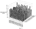
- Table 1 is of a case in which the group of battery modules 1 has no variability in the performance index (all 0.5), and the system performance is 5.000 (also see FIG. 4 ).
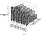
- table 2 is of a case in which the group of battery modules 1 automatically generated a random number of average 0.5 and standard deviation 0.1 as the performance index, and the system performance is 3. 605 (also see FIG. 5 ).
- FIG. 6 shows a flowchart of a method of arranging the battery modules 1 according to the present embodiment.
- the expression for a system scale is further generalized, and the number of battery cabinet is defined as Np_max, and the number of modules in a battery cabinet is defined as Nm_max.
- the deterioration inspecting block 11 of the battery controller 7 executes deterioration inspection on all battery modules 1 by for example estimating the capacity of each battery module 1. (step S1).
- the capacity estimation is first performed on each cell, and the minimum cell capacity in the target battery module 1 is determined as the capacity of the battery module 1.
- the numbering block 12 ranks all battery modules 1 in the secondary battery system 10 in the descending order of the capacity estimated in the step S1. That is to say, they are numbered from 1 to Np_max ⁇ Nm_max in this order (step S2).
- the numbering block 12 performs numbering on all battery cabinets 2 in the system from 1 to Np_max in the ascending order of the distance of the wiring from the PCS 3 (step S3).
- the re-arrangement determining block 13 initializes the battery cabinet number Np subjected to the re-arrangement and the battery module number Nm subjected to the re-arrangement in said battery cabinet (step S4, step S5).
- the re-arrangement determining block 13 determines the battery module 1 that has the smallest number in the group of unarranged battery modules to be arranged at the Nm-th stage from the top stage in the battery cabinet 2 number Np (step S6). That is, if it is a first determination, the determination is made in such a way that the battery module 1 number 1 is arranged at the top stage in the battery cabinet 2 nearest the PCS 3.
- the re-arrangement determining block 13 repeats the process of the step S6 to the same battery cabinet 2, thereby completing the determination of the position re-arrangement of the battery modules 1 in said battery cabinet 2 (step S7, step S8).
- the re-arrangement determining block 13 repeats the processes of the steps S6-S8, thereby completing the determination of the position re-arrangement of the battery modules 1 for all battery cabinets 2 in the system (step S9, step S10).
- the battery modules 1 are actually re-arranged based on the position re-arrangement of the battery modules 1 determined in the process illustrated in FIG. 6 .
- the re-arrangement may be performed by unillustrated re-arranging means.
- Table 3 shows a relationship between the battery cabinet 2and the battery module 1, and the performance index of when the re-arrangement determination is made by the procedures illustrated in FIG. 6 with the characteristic variability being present among the battery modules 1 illustrated in table 2.
- the method of re-arranging the battery modules according to the present embodiment is suitably applicable to maintain the system performance of, in particular, a large-scale secondary battery system operated for a long term.
- the method is also applicable to an initial arrangement of a secondary battery system that initially includes a group of battery modules which have various characteristics.
Landscapes
- Engineering & Computer Science (AREA)
- Chemical & Material Sciences (AREA)
- Chemical Kinetics & Catalysis (AREA)
- Electrochemistry (AREA)
- General Chemical & Material Sciences (AREA)
- Manufacturing & Machinery (AREA)
- Power Engineering (AREA)
- Microelectronics & Electronic Packaging (AREA)
- Physics & Mathematics (AREA)
- General Physics & Mathematics (AREA)
- Charge And Discharge Circuits For Batteries Or The Like (AREA)
- Secondary Cells (AREA)
- Battery Mounting, Suspending (AREA)
Applications Claiming Priority (2)
| Application Number | Priority Date | Filing Date | Title |
|---|---|---|---|
| JP2014075317 | 2014-04-01 | ||
| PCT/JP2015/055160 WO2015151652A1 (fr) | 2014-04-01 | 2015-02-24 | Système de cellules de mémoire et procédé pour agencer un module de cellules |
Publications (3)
| Publication Number | Publication Date |
|---|---|
| EP3128641A1 true EP3128641A1 (fr) | 2017-02-08 |
| EP3128641A4 EP3128641A4 (fr) | 2017-11-08 |
| EP3128641B1 EP3128641B1 (fr) | 2020-01-29 |
Family
ID=54239988
Family Applications (1)
| Application Number | Title | Priority Date | Filing Date |
|---|---|---|---|
| EP15772298.4A Active EP3128641B1 (fr) | 2014-04-01 | 2015-02-24 | Système de cellules de mémoire et procédé pour agencer un module de cellules |
Country Status (7)
| Country | Link |
|---|---|
| US (1) | US10263295B2 (fr) |
| EP (1) | EP3128641B1 (fr) |
| JP (1) | JP6356785B2 (fr) |
| KR (1) | KR20160101036A (fr) |
| CN (1) | CN106030967B (fr) |
| ES (1) | ES2780003T3 (fr) |
| WO (1) | WO2015151652A1 (fr) |
Families Citing this family (17)
| Publication number | Priority date | Publication date | Assignee | Title |
|---|---|---|---|---|
| US10742243B2 (en) | 2015-07-14 | 2020-08-11 | At&T Intellectual Property I, L.P. | Method and apparatus for coupling an antenna to a device |
| US10129057B2 (en) | 2015-07-14 | 2018-11-13 | At&T Intellectual Property I, L.P. | Apparatus and methods for inducing electromagnetic waves on a cable |
| US10341142B2 (en) | 2015-07-14 | 2019-07-02 | At&T Intellectual Property I, L.P. | Apparatus and methods for generating non-interfering electromagnetic waves on an uninsulated conductor |
| US10320586B2 (en) | 2015-07-14 | 2019-06-11 | At&T Intellectual Property I, L.P. | Apparatus and methods for generating non-interfering electromagnetic waves on an insulated transmission medium |
| US9722318B2 (en) | 2015-07-14 | 2017-08-01 | At&T Intellectual Property I, L.P. | Method and apparatus for coupling an antenna to a device |
| US10033107B2 (en) | 2015-07-14 | 2018-07-24 | At&T Intellectual Property I, L.P. | Method and apparatus for coupling an antenna to a device |
| US10978884B2 (en) | 2018-08-10 | 2021-04-13 | Powin Energy Corporation | Enhanced switched balancing network for battery pack |
| EP3850687A4 (fr) * | 2018-09-11 | 2022-07-20 | Powin, LLC | Empilement de batteries modulaires et système de support |
| CN109714414A (zh) * | 2018-12-26 | 2019-05-03 | 深圳云动未来科技有限公司 | 物联网平台、电动车、电动车更换电池方法及系统 |
| CN110007625A (zh) * | 2019-03-29 | 2019-07-12 | 安徽贵博新能科技有限公司 | 一种电池管理系统中配置从机编号的装置及配置方法 |
| EP3772657B1 (fr) | 2019-08-08 | 2023-10-04 | ABB Schweiz AG | Dispositif et procédé pour effectuer une estimation de l'état de santé |
| JP2022007522A (ja) | 2020-06-26 | 2022-01-13 | 株式会社Gsユアサ | 温度推定装置、コンピュータプログラム及び温度推定方法 |
| WO2022157815A1 (fr) * | 2021-01-19 | 2022-07-28 | 株式会社東芝 | Dispositif et procédé de gestion de batterie de stockage, et programme |
| CN114137418A (zh) * | 2021-11-29 | 2022-03-04 | 中国南方电网有限责任公司超高压输电公司昆明局 | 蓄电池性能识别方法、装置、计算机设备和存储介质 |
| KR20230157646A (ko) * | 2022-05-10 | 2023-11-17 | 주식회사 엘지에너지솔루션 | 내부 저항 평가 장치 및 배터리 시스템 |
| WO2023238332A1 (fr) * | 2022-06-09 | 2023-12-14 | 三菱電機株式会社 | Système de stockage d'énergie et système de commande d'énergie électrique |
| CN117405975B (zh) * | 2023-12-14 | 2024-03-22 | 深圳鹏城新能科技有限公司 | 一种pv面板绝缘电阻检测方法、系统及介质 |
Family Cites Families (13)
| Publication number | Priority date | Publication date | Assignee | Title |
|---|---|---|---|---|
| JPH11234909A (ja) * | 1998-02-16 | 1999-08-27 | Nec Corp | 蓄電池を用いた電源装置 |
| JP4001708B2 (ja) * | 2000-04-28 | 2007-10-31 | 松下電器産業株式会社 | 二次電池の交換方法 |
| JP4542536B2 (ja) | 2006-11-06 | 2010-09-15 | 株式会社日立製作所 | 電源制御装置 |
| KR20120060820A (ko) | 2009-09-01 | 2012-06-12 | 보스톤-파워, 인크. | 대형 배터리 시스템 및 조립 방법 |
| US20120119749A1 (en) * | 2010-03-26 | 2012-05-17 | Takuma Iida | Charge state detection circuit, battery power supply device, and battery information monitoring device |
| JP2012034439A (ja) * | 2010-07-28 | 2012-02-16 | Sumitomo Electric Ind Ltd | 直流電源装置及び電力貯蔵システム |
| JP5541210B2 (ja) | 2011-03-29 | 2014-07-09 | 株式会社デンソー | 電力分配装置 |
| JP5747610B2 (ja) * | 2011-03-30 | 2015-07-15 | ソニー株式会社 | 充電制御装置、充電制御方法、プログラム及びシステム |
| JP5463324B2 (ja) | 2011-06-01 | 2014-04-09 | 三菱重工業株式会社 | 組電池システム |
| EP2587614A2 (fr) * | 2011-08-31 | 2013-05-01 | Sony Corporation | Appareil de stockage électrique, dispositif électronique, véhicule électrique et système d'alimentation électrique |
| JP2014011060A (ja) * | 2012-06-29 | 2014-01-20 | Sanyo Electric Co Ltd | 電池モジュールの入れ替え方法、電源システム、これを備える車両、蓄電装置及び入れ替え管理プログラム |
| US20160056510A1 (en) * | 2012-12-28 | 2016-02-25 | Hitachi, Ltd. | Assembled battery system, storage battery system, and method for monitoring and controlling assembled battery system |
| US9537332B2 (en) * | 2013-05-30 | 2017-01-03 | Canara, Inc. | Apparatus, system and method for charge balancing of individual batteries in a string of batteries using battery voltage and temperature, and detecting and preventing thermal runaway |
-
2015
- 2015-02-24 WO PCT/JP2015/055160 patent/WO2015151652A1/fr active Application Filing
- 2015-02-24 ES ES15772298T patent/ES2780003T3/es active Active
- 2015-02-24 EP EP15772298.4A patent/EP3128641B1/fr active Active
- 2015-02-24 US US15/301,321 patent/US10263295B2/en active Active
- 2015-02-24 JP JP2016511450A patent/JP6356785B2/ja active Active
- 2015-02-24 KR KR1020167018972A patent/KR20160101036A/ko not_active Application Discontinuation
- 2015-02-24 CN CN201580010149.0A patent/CN106030967B/zh active Active
Also Published As
| Publication number | Publication date |
|---|---|
| JPWO2015151652A1 (ja) | 2017-04-13 |
| US20170033410A1 (en) | 2017-02-02 |
| CN106030967A (zh) | 2016-10-12 |
| EP3128641A4 (fr) | 2017-11-08 |
| CN106030967B (zh) | 2019-09-03 |
| KR20160101036A (ko) | 2016-08-24 |
| ES2780003T3 (es) | 2020-08-21 |
| EP3128641B1 (fr) | 2020-01-29 |
| JP6356785B2 (ja) | 2018-07-11 |
| WO2015151652A1 (fr) | 2015-10-08 |
| US10263295B2 (en) | 2019-04-16 |
Similar Documents
| Publication | Publication Date | Title |
|---|---|---|
| EP3128641B1 (fr) | Système de cellules de mémoire et procédé pour agencer un module de cellules | |
| US20130020997A1 (en) | Battery System | |
| JP6072327B2 (ja) | 蓄電池装置、蓄電池装置の制御方法及び制御プログラム | |
| US9537327B2 (en) | Battery cell balancing control system and battery management method thereof | |
| US9529048B2 (en) | Transient detection of an exceptional charge event in a series connected battery element | |
| US10355498B2 (en) | Response to detection of an overdischarge event in a series connected battery element | |
| JP6439866B2 (ja) | 蓄電装置及び接続制御方法 | |
| JP6174154B2 (ja) | 蓄電池管理装置、方法及びプログラム | |
| CN114156552A (zh) | 一种考虑老化的串联电池组的均衡控制策略 | |
| JP2019029141A (ja) | センサ選択装置およびセンサ選択方法 | |
| JP6125710B1 (ja) | 蓄電池装置、蓄電池システム、方法及びプログラム | |
| WO2015133401A1 (fr) | Unité de commande, système de batterie de stockage, procédé d'équilibrage de cellules de batterie, et programme | |
| JP6622380B2 (ja) | 蓄電池装置及び方法 | |
| Hannan et al. | Lithium ion battery thermal management system using optimized fuzzy controller | |
| CN112083342A (zh) | 监视电池的方法和装置 | |
| Freitas et al. | Lifetime estimation technique for lead-acid batteries | |
| US9343911B2 (en) | Response to detection of an overcharge event in a series connected battery element | |
| CN108973709B (zh) | 用于运行具有不同化学组成区的模块的电池组的确定电池部分特性的方法 | |
| JP2012028049A (ja) | 蓄電装置の製造方法および蓄電装置 | |
| Savard et al. | Increase lifespan with a cell management algorithm in electric energy storage systems | |
| US20200269715A1 (en) | Method and system for intelligently managing electrochemical batteries of an electrical power supply installation | |
| EP4307440A1 (fr) | Système de commande de batterie pour prévenir un déséquilibre entre des éléments de batterie et procédé de commande associé | |
| US9252619B2 (en) | Method for the resistive cell equalization of battery cells of a battery, a battery which is controlled in accordance with the method, and a motor vehicle | |
| Ren et al. | The charging and discharging balance control strategy of power batteries for hybrid energy storage | |
| JP2015171216A (ja) | 蓄電池システム及び蓄電池システムの充電方法 |
Legal Events
| Date | Code | Title | Description |
|---|---|---|---|
| STAA | Information on the status of an ep patent application or granted ep patent |
Free format text: STATUS: THE INTERNATIONAL PUBLICATION HAS BEEN MADE |
|
| PUAI | Public reference made under article 153(3) epc to a published international application that has entered the european phase |
Free format text: ORIGINAL CODE: 0009012 |
|
| STAA | Information on the status of an ep patent application or granted ep patent |
Free format text: STATUS: REQUEST FOR EXAMINATION WAS MADE |
|
| 17P | Request for examination filed |
Effective date: 20160927 |
|
| AK | Designated contracting states |
Kind code of ref document: A1 Designated state(s): AL AT BE BG CH CY CZ DE DK EE ES FI FR GB GR HR HU IE IS IT LI LT LU LV MC MK MT NL NO PL PT RO RS SE SI SK SM TR |
|
| AX | Request for extension of the european patent |
Extension state: BA ME |
|
| DAX | Request for extension of the european patent (deleted) | ||
| A4 | Supplementary search report drawn up and despatched |
Effective date: 20171006 |
|
| RIC1 | Information provided on ipc code assigned before grant |
Ipc: H01M 10/48 20060101ALI20170929BHEP Ipc: H01M 2/10 20060101ALI20170929BHEP Ipc: H02J 7/00 20060101AFI20170929BHEP Ipc: H01M 10/42 20060101ALI20170929BHEP Ipc: H02J 7/34 20060101ALI20170929BHEP |
|
| STAA | Information on the status of an ep patent application or granted ep patent |
Free format text: STATUS: EXAMINATION IS IN PROGRESS |
|
| 17Q | First examination report despatched |
Effective date: 20190311 |
|
| GRAP | Despatch of communication of intention to grant a patent |
Free format text: ORIGINAL CODE: EPIDOSNIGR1 |
|
| STAA | Information on the status of an ep patent application or granted ep patent |
Free format text: STATUS: GRANT OF PATENT IS INTENDED |
|
| INTG | Intention to grant announced |
Effective date: 20190826 |
|
| GRAS | Grant fee paid |
Free format text: ORIGINAL CODE: EPIDOSNIGR3 |
|
| GRAA | (expected) grant |
Free format text: ORIGINAL CODE: 0009210 |
|
| STAA | Information on the status of an ep patent application or granted ep patent |
Free format text: STATUS: THE PATENT HAS BEEN GRANTED |
|
| AK | Designated contracting states |
Kind code of ref document: B1 Designated state(s): AL AT BE BG CH CY CZ DE DK EE ES FI FR GB GR HR HU IE IS IT LI LT LU LV MC MK MT NL NO PL PT RO RS SE SI SK SM TR |
|
| REG | Reference to a national code |
Ref country code: GB Ref legal event code: FG4D |
|
| REG | Reference to a national code |
Ref country code: CH Ref legal event code: EP |
|
| REG | Reference to a national code |
Ref country code: AT Ref legal event code: REF Ref document number: 1229107 Country of ref document: AT Kind code of ref document: T Effective date: 20200215 |
|
| REG | Reference to a national code |
Ref country code: IE Ref legal event code: FG4D |
|
| REG | Reference to a national code |
Ref country code: DE Ref legal event code: R096 Ref document number: 602015046072 Country of ref document: DE |
|
| REG | Reference to a national code |
Ref country code: NL Ref legal event code: MP Effective date: 20200129 |
|
| PG25 | Lapsed in a contracting state [announced via postgrant information from national office to epo] |
Ref country code: PT Free format text: LAPSE BECAUSE OF FAILURE TO SUBMIT A TRANSLATION OF THE DESCRIPTION OR TO PAY THE FEE WITHIN THE PRESCRIBED TIME-LIMIT Effective date: 20200621 Ref country code: NO Free format text: LAPSE BECAUSE OF FAILURE TO SUBMIT A TRANSLATION OF THE DESCRIPTION OR TO PAY THE FEE WITHIN THE PRESCRIBED TIME-LIMIT Effective date: 20200429 Ref country code: FI Free format text: LAPSE BECAUSE OF FAILURE TO SUBMIT A TRANSLATION OF THE DESCRIPTION OR TO PAY THE FEE WITHIN THE PRESCRIBED TIME-LIMIT Effective date: 20200129 Ref country code: RS Free format text: LAPSE BECAUSE OF FAILURE TO SUBMIT A TRANSLATION OF THE DESCRIPTION OR TO PAY THE FEE WITHIN THE PRESCRIBED TIME-LIMIT Effective date: 20200129 |
|
| REG | Reference to a national code |
Ref country code: LT Ref legal event code: MG4D |
|
| REG | Reference to a national code |
Ref country code: ES Ref legal event code: FG2A Ref document number: 2780003 Country of ref document: ES Kind code of ref document: T3 Effective date: 20200821 |
|
| PG25 | Lapsed in a contracting state [announced via postgrant information from national office to epo] |
Ref country code: BG Free format text: LAPSE BECAUSE OF FAILURE TO SUBMIT A TRANSLATION OF THE DESCRIPTION OR TO PAY THE FEE WITHIN THE PRESCRIBED TIME-LIMIT Effective date: 20200429 Ref country code: IS Free format text: LAPSE BECAUSE OF FAILURE TO SUBMIT A TRANSLATION OF THE DESCRIPTION OR TO PAY THE FEE WITHIN THE PRESCRIBED TIME-LIMIT Effective date: 20200529 Ref country code: LV Free format text: LAPSE BECAUSE OF FAILURE TO SUBMIT A TRANSLATION OF THE DESCRIPTION OR TO PAY THE FEE WITHIN THE PRESCRIBED TIME-LIMIT Effective date: 20200129 Ref country code: SE Free format text: LAPSE BECAUSE OF FAILURE TO SUBMIT A TRANSLATION OF THE DESCRIPTION OR TO PAY THE FEE WITHIN THE PRESCRIBED TIME-LIMIT Effective date: 20200129 Ref country code: HR Free format text: LAPSE BECAUSE OF FAILURE TO SUBMIT A TRANSLATION OF THE DESCRIPTION OR TO PAY THE FEE WITHIN THE PRESCRIBED TIME-LIMIT Effective date: 20200129 Ref country code: GR Free format text: LAPSE BECAUSE OF FAILURE TO SUBMIT A TRANSLATION OF THE DESCRIPTION OR TO PAY THE FEE WITHIN THE PRESCRIBED TIME-LIMIT Effective date: 20200430 |
|
| PG25 | Lapsed in a contracting state [announced via postgrant information from national office to epo] |
Ref country code: NL Free format text: LAPSE BECAUSE OF FAILURE TO SUBMIT A TRANSLATION OF THE DESCRIPTION OR TO PAY THE FEE WITHIN THE PRESCRIBED TIME-LIMIT Effective date: 20200129 |
|
| REG | Reference to a national code |
Ref country code: BE Ref legal event code: MM Effective date: 20200229 |
|
| PG25 | Lapsed in a contracting state [announced via postgrant information from national office to epo] |
Ref country code: MC Free format text: LAPSE BECAUSE OF FAILURE TO SUBMIT A TRANSLATION OF THE DESCRIPTION OR TO PAY THE FEE WITHIN THE PRESCRIBED TIME-LIMIT Effective date: 20200129 Ref country code: LU Free format text: LAPSE BECAUSE OF NON-PAYMENT OF DUE FEES Effective date: 20200224 Ref country code: SK Free format text: LAPSE BECAUSE OF FAILURE TO SUBMIT A TRANSLATION OF THE DESCRIPTION OR TO PAY THE FEE WITHIN THE PRESCRIBED TIME-LIMIT Effective date: 20200129 Ref country code: RO Free format text: LAPSE BECAUSE OF FAILURE TO SUBMIT A TRANSLATION OF THE DESCRIPTION OR TO PAY THE FEE WITHIN THE PRESCRIBED TIME-LIMIT Effective date: 20200129 Ref country code: LT Free format text: LAPSE BECAUSE OF FAILURE TO SUBMIT A TRANSLATION OF THE DESCRIPTION OR TO PAY THE FEE WITHIN THE PRESCRIBED TIME-LIMIT Effective date: 20200129 Ref country code: CZ Free format text: LAPSE BECAUSE OF FAILURE TO SUBMIT A TRANSLATION OF THE DESCRIPTION OR TO PAY THE FEE WITHIN THE PRESCRIBED TIME-LIMIT Effective date: 20200129 Ref country code: DK Free format text: LAPSE BECAUSE OF FAILURE TO SUBMIT A TRANSLATION OF THE DESCRIPTION OR TO PAY THE FEE WITHIN THE PRESCRIBED TIME-LIMIT Effective date: 20200129 Ref country code: SM Free format text: LAPSE BECAUSE OF FAILURE TO SUBMIT A TRANSLATION OF THE DESCRIPTION OR TO PAY THE FEE WITHIN THE PRESCRIBED TIME-LIMIT Effective date: 20200129 Ref country code: EE Free format text: LAPSE BECAUSE OF FAILURE TO SUBMIT A TRANSLATION OF THE DESCRIPTION OR TO PAY THE FEE WITHIN THE PRESCRIBED TIME-LIMIT Effective date: 20200129 |
|
| REG | Reference to a national code |
Ref country code: DE Ref legal event code: R097 Ref document number: 602015046072 Country of ref document: DE |
|
| REG | Reference to a national code |
Ref country code: AT Ref legal event code: MK05 Ref document number: 1229107 Country of ref document: AT Kind code of ref document: T Effective date: 20200129 |
|
| PLBE | No opposition filed within time limit |
Free format text: ORIGINAL CODE: 0009261 |
|
| STAA | Information on the status of an ep patent application or granted ep patent |
Free format text: STATUS: NO OPPOSITION FILED WITHIN TIME LIMIT |
|
| 26N | No opposition filed |
Effective date: 20201030 |
|
| PG25 | Lapsed in a contracting state [announced via postgrant information from national office to epo] |
Ref country code: IE Free format text: LAPSE BECAUSE OF NON-PAYMENT OF DUE FEES Effective date: 20200224 Ref country code: AT Free format text: LAPSE BECAUSE OF FAILURE TO SUBMIT A TRANSLATION OF THE DESCRIPTION OR TO PAY THE FEE WITHIN THE PRESCRIBED TIME-LIMIT Effective date: 20200129 |
|
| PG25 | Lapsed in a contracting state [announced via postgrant information from national office to epo] |
Ref country code: PL Free format text: LAPSE BECAUSE OF FAILURE TO SUBMIT A TRANSLATION OF THE DESCRIPTION OR TO PAY THE FEE WITHIN THE PRESCRIBED TIME-LIMIT Effective date: 20200129 Ref country code: SI Free format text: LAPSE BECAUSE OF FAILURE TO SUBMIT A TRANSLATION OF THE DESCRIPTION OR TO PAY THE FEE WITHIN THE PRESCRIBED TIME-LIMIT Effective date: 20200129 Ref country code: BE Free format text: LAPSE BECAUSE OF NON-PAYMENT OF DUE FEES Effective date: 20200229 |
|
| PG25 | Lapsed in a contracting state [announced via postgrant information from national office to epo] |
Ref country code: TR Free format text: LAPSE BECAUSE OF FAILURE TO SUBMIT A TRANSLATION OF THE DESCRIPTION OR TO PAY THE FEE WITHIN THE PRESCRIBED TIME-LIMIT Effective date: 20200129 Ref country code: MT Free format text: LAPSE BECAUSE OF FAILURE TO SUBMIT A TRANSLATION OF THE DESCRIPTION OR TO PAY THE FEE WITHIN THE PRESCRIBED TIME-LIMIT Effective date: 20200129 Ref country code: CY Free format text: LAPSE BECAUSE OF FAILURE TO SUBMIT A TRANSLATION OF THE DESCRIPTION OR TO PAY THE FEE WITHIN THE PRESCRIBED TIME-LIMIT Effective date: 20200129 |
|
| PG25 | Lapsed in a contracting state [announced via postgrant information from national office to epo] |
Ref country code: MK Free format text: LAPSE BECAUSE OF FAILURE TO SUBMIT A TRANSLATION OF THE DESCRIPTION OR TO PAY THE FEE WITHIN THE PRESCRIBED TIME-LIMIT Effective date: 20200129 Ref country code: AL Free format text: LAPSE BECAUSE OF FAILURE TO SUBMIT A TRANSLATION OF THE DESCRIPTION OR TO PAY THE FEE WITHIN THE PRESCRIBED TIME-LIMIT Effective date: 20200129 |
|
| PGFP | Annual fee paid to national office [announced via postgrant information from national office to epo] |
Ref country code: IT Payment date: 20230110 Year of fee payment: 9 |
|
| PGFP | Annual fee paid to national office [announced via postgrant information from national office to epo] |
Ref country code: FR Payment date: 20231229 Year of fee payment: 10 |
|
| PGFP | Annual fee paid to national office [announced via postgrant information from national office to epo] |
Ref country code: ES Payment date: 20240305 Year of fee payment: 10 |
|
| PGFP | Annual fee paid to national office [announced via postgrant information from national office to epo] |
Ref country code: DE Payment date: 20231229 Year of fee payment: 10 Ref country code: GB Payment date: 20240108 Year of fee payment: 10 Ref country code: CH Payment date: 20240301 Year of fee payment: 10 |