EP3126927B1 - Method and system for optimizing performance of a pcd while mitigating thermal generation - Google Patents
Method and system for optimizing performance of a pcd while mitigating thermal generation Download PDFInfo
- Publication number
- EP3126927B1 EP3126927B1 EP15716353.6A EP15716353A EP3126927B1 EP 3126927 B1 EP3126927 B1 EP 3126927B1 EP 15716353 A EP15716353 A EP 15716353A EP 3126927 B1 EP3126927 B1 EP 3126927B1
- Authority
- EP
- European Patent Office
- Prior art keywords
- temperature
- parameter
- value
- computing device
- portable computing
- Prior art date
- Legal status (The legal status is an assumption and is not a legal conclusion. Google has not performed a legal analysis and makes no representation as to the accuracy of the status listed.)
- Active
Links
Images


Classifications
-
- G—PHYSICS
- G06—COMPUTING OR CALCULATING; COUNTING
- G06F—ELECTRIC DIGITAL DATA PROCESSING
- G06F1/00—Details not covered by groups G06F3/00 - G06F13/00 and G06F21/00
- G06F1/16—Constructional details or arrangements
- G06F1/20—Cooling means
- G06F1/206—Cooling means comprising thermal management
-
- G—PHYSICS
- G05—CONTROLLING; REGULATING
- G05B—CONTROL OR REGULATING SYSTEMS IN GENERAL; FUNCTIONAL ELEMENTS OF SUCH SYSTEMS; MONITORING OR TESTING ARRANGEMENTS FOR SUCH SYSTEMS OR ELEMENTS
- G05B11/00—Automatic controllers
- G05B11/01—Automatic controllers electric
- G05B11/36—Automatic controllers electric with provision for obtaining particular characteristics, e.g. proportional, integral, differential
- G05B11/42—Automatic controllers electric with provision for obtaining particular characteristics, e.g. proportional, integral, differential for obtaining a characteristic which is both proportional and time-dependent, e.g. P. I., P. I. D.
-
- G—PHYSICS
- G06—COMPUTING OR CALCULATING; COUNTING
- G06F—ELECTRIC DIGITAL DATA PROCESSING
- G06F1/00—Details not covered by groups G06F3/00 - G06F13/00 and G06F21/00
- G06F1/16—Constructional details or arrangements
- G06F1/20—Cooling means
- G06F1/203—Cooling means for portable computers, e.g. for laptops
-
- G—PHYSICS
- G06—COMPUTING OR CALCULATING; COUNTING
- G06F—ELECTRIC DIGITAL DATA PROCESSING
- G06F1/00—Details not covered by groups G06F3/00 - G06F13/00 and G06F21/00
- G06F1/26—Power supply means, e.g. regulation thereof
- G06F1/32—Means for saving power
- G06F1/3203—Power management, i.e. event-based initiation of a power-saving mode
- G06F1/3234—Power saving characterised by the action undertaken
- G06F1/324—Power saving characterised by the action undertaken by lowering clock frequency
-
- G—PHYSICS
- G06—COMPUTING OR CALCULATING; COUNTING
- G06F—ELECTRIC DIGITAL DATA PROCESSING
- G06F1/00—Details not covered by groups G06F3/00 - G06F13/00 and G06F21/00
- G06F1/26—Power supply means, e.g. regulation thereof
- G06F1/32—Means for saving power
- G06F1/3203—Power management, i.e. event-based initiation of a power-saving mode
- G06F1/3234—Power saving characterised by the action undertaken
- G06F1/3296—Power saving characterised by the action undertaken by lowering the supply or operating voltage
-
- H—ELECTRICITY
- H01—ELECTRIC ELEMENTS
- H01L—SEMICONDUCTOR DEVICES NOT COVERED BY CLASS H10
- H01L23/00—Details of semiconductor or other solid state devices
- H01L23/34—Arrangements for cooling, heating, ventilating or temperature compensation ; Temperature sensing arrangements
-
- H—ELECTRICITY
- H01—ELECTRIC ELEMENTS
- H01L—SEMICONDUCTOR DEVICES NOT COVERED BY CLASS H10
- H01L23/00—Details of semiconductor or other solid state devices
- H01L23/34—Arrangements for cooling, heating, ventilating or temperature compensation ; Temperature sensing arrangements
- H01L23/345—Arrangements for heating
-
- Y—GENERAL TAGGING OF NEW TECHNOLOGICAL DEVELOPMENTS; GENERAL TAGGING OF CROSS-SECTIONAL TECHNOLOGIES SPANNING OVER SEVERAL SECTIONS OF THE IPC; TECHNICAL SUBJECTS COVERED BY FORMER USPC CROSS-REFERENCE ART COLLECTIONS [XRACs] AND DIGESTS
- Y02—TECHNOLOGIES OR APPLICATIONS FOR MITIGATION OR ADAPTATION AGAINST CLIMATE CHANGE
- Y02D—CLIMATE CHANGE MITIGATION TECHNOLOGIES IN INFORMATION AND COMMUNICATION TECHNOLOGIES [ICT], I.E. INFORMATION AND COMMUNICATION TECHNOLOGIES AIMING AT THE REDUCTION OF THEIR OWN ENERGY USE
- Y02D10/00—Energy efficient computing, e.g. low power processors, power management or thermal management
Definitions
- PCDs Portable computing devices
- PCDs Portable computing devices
- PCDs are becoming necessities for people. And optimal performance is desired for these battery operated devices. To achieve optimal performance, PCDs need to manage their internal temperature constantly. PCDs are battery operated devices and therefore, most PCDs do not have any active cooling devices, like fans. So PCDs use thermal mitigation algorithms. Thermal mitigation algorithms help in cooling a PCD passively when it gets hotter than a prescribed temperature threshold.
- the thermal mitigation algorithms rely on embedded, on-die thermal sensors (TSENS) to obtain the instantaneous temperature of the various components (e.g., central processing unit ["CPU”] cores, graphics processing unit ["GPU”] cores, modems, etc.) present within a PCD.
- TSENS embedded, on-die thermal sensors
- the thermal algorithm(s) are usually designed to throttle those components to reduce their heat generation.
- the thermal mitigation algorithm(s) usually must be capable of adapting the device parameters to the heating characteristics of the device to effectively cool them down.
- throttling the operating frequency of a CPU or GPU of a PCD may negatively impact the overall performance of the device.
- throttling data rate and/or transmit power for modems of a PCD may also negatively impact the performance of the device.
- CLs battery current limitations
- a CL situation may arise when, for instance, a CPU core of a PCD (such as a mobile phone) becomes more active when other cores are actively loaded, or a data call is initiated during a voice call, or the camera flash is activated while playing a game on the device.
- the CL situation may become worse when the battery charge is already low and/r when the temperature of the PCD rises.
- an “application” may also include files having executable content, such as: object code, scripts, byte code, markup language files, and patches.
- an “application” referred to herein may also include files that are not executable in nature, such as documents that may need to be opened or other data files that need to be accessed.
- content may also include files having executable content, such as: object code, scripts, byte code, markup language files, and patches.
- content referred to herein, may also include files that are not executable in nature, such as documents that may need to be opened or other data files that need to be accessed.
- a component may be, but is not limited to being, a process running on a processor, a processor, an object, an executable, a thread of execution, a program, and/or a computer.
- an application running on a computing device and the computing device may be a component.
- One or more components may reside within a process and/or thread of execution, and a component may be localized on one computer and/or distributed between two or more computers.
- these components may execute from various computer readable media having various data structures stored thereon.
- the components may communicate by way of local and/or remote processes such as in accordance with a signal having one or more data packets (e . g ., data from one component interacting with another component in a local system, distributed system, and/or across a network such as the Internet with other systems by way of the signal).
- wireless device In this description, the terms “communication device,” “wireless device,” “wireless telephone,” “wireless communication device,” and “wireless handset” are used interchangeably.
- 3G third generation
- 4G fourth generation
- PCD portable computing device
- 3G third generation
- a PCD may be a cellular telephone, a satellite telephone, a pager, a PDA, a smartphone, a navigation device, a smartbook or reader, a media player, a combination of the aforementioned devices, and a laptop computer with a wireless connection, among others.
- FIG. 1 this figure is a functional block diagram of an exemplary, non-limiting aspect of a PCD 100 in the form of a wireless telephone for implementing methods and systems for optimizing performance of the PCD 100 and while mitigating thermal generation within the PCD 100.
- the PCD 100 includes an on-chip system 102 that includes a multi-core central processing unit (“CPU") 110 and an analog signal processor 126 that are coupled together.
- the CPU 110 may comprise a zeroth core 222, a first core 224, and an Nth core 230 as understood by one of ordinary skill in the art.
- a digital signal processor DSP
- DSP digital signal processor
- the CPU 110 may also be coupled to one or more internal, on-chip thermal sensors 157A-B as well as one or more external, off-chip thermal sensors 157C-D.
- the on-chip thermal sensors 157A-B may comprise one or more proportional to absolute temperature (“PTAT”) temperature sensors that are based on vertical PNP structure and are usually dedicated to complementary metal oxide semiconductor (“CMOS”) very large-scale integration (“VLSI”) circuits.
- CMOS complementary metal oxide semiconductor
- VLSI very large-scale integration
- the off-chip thermal sensors 157C-D may comprise one or more thermistors.
- the thermal sensors 157 may produce a voltage drop (and/or a current) that is converted to digital signals with an analog-to-digital converter ("ADC") (not illustrated).
- ADC analog-to-digital converter
- other types of thermal sensors 157 may be employed without departing from the scope of this disclosure.
- the PCD 100 of FIG. 1 may include and/or be coupled to a dual proportional integral derivative ("PID") loop controller 205.
- the dual PID loop controller 205 may comprise hardware, software, firmware, or a combination thereof.
- the dual PID loop controller 205 may be responsible for monitoring temperature of the PCD 100 and adjusting one or more parameters based on whether a temperature threshold or limit has been reached/achieved.
- Such parameters include, but are not limited to, an operating frequency of a component such as the CPU 110, processor 126, and/or GPU 189; transmission power of the RF transceiver 168 which may comprise a modem; data rate or flow rates of the processor 126; as well as other parameters of the PCD 100 which may mitigate thermal generation and that may also impact operating performance of the PCD 100.
- the dual PID loop controller 205 comprises two controllers (see FIG. 2A ) which calculate separate error values relative to each other. One controller is provided with a temperature input while the other controller is provided with an input of an adjustable parameter. One interesting aspect of the dual PID loop controller 205 is that each PID controller has output that may control/impact the same adjustable parameter, such as operating frequency.
- the exemplary embodiment of the dual PID loop controller 205 of FIGs. 1 and 2A show the dual PID loop controller 205 for controlling the operating frequency of the CPU 110.
- the dual PID loop controller 205 may be coupled and/or logically connected to any component and/or a plurality of components within the PCD 100.
- the dual PID loop controller 205 may also adjust parameters other than operating frequency of a component, such as, but not limited to, transmission power, data flow rates, etc. as mentioned above.
- one or more of the method steps for the dual PID loop controller 205 described herein may be implemented by executable instructions and parameters, stored in the memory 112, that may form software embodiments of the dual PID loop controller 205. These instructions that form the dual PID loop controller 205 may be executed by the CPU 110, the analog signal processor 126, or any other processor. Further, the processors, 110, 126, the memory 112, the instructions stored therein, or a combination thereof may serve as a means for performing one or more of the method steps described herein.
- the power manager integrated controller (“PMIC”) 107 may be responsible for distributing power to the various hardware components present on the chip 102.
- the PMIC is coupled to a power supply 180.
- the power supply 180 may comprise a battery and it may be coupled to the on-chip system 102.
- the power supply may include a rechargeable direct current (“DC”) battery or a DC power supply that is derived from an alternating current (“AC”) to DC transformer that is connected to an AC power source.
- DC direct current
- AC alternating current
- a display controller 128 and a touchscreen controller 130 are coupled to the multi-core processor 110.
- a touchscreen display 132 external to the on-chip system 102 is coupled to the display controller 128 and the touchscreen controller 130.
- FIG. 1 is a schematic diagram illustrating an embodiment of a portable computing device (PCD) that includes a video decoder 134.
- the video decoder 134 is coupled to the multicore central processing unit ("CPU") 110.
- a video amplifier 136 is coupled to the video decoder 134 and the touchscreen display 132.
- a video port 138 is coupled to the video amplifier 136.
- a universal serial bus (“USB") controller 140 is coupled to the CPU 110.
- a USB port 142 is coupled to the USB controller 140.
- a memory 112 and a subscriber identity module (SIM) card 146 may also be coupled to the CPU 110.
- SIM subscriber identity module
- a digital camera or camera subsystem 148 may be coupled to the CPU 110.
- the digital camera/cameral subsystem 148 is a charge-coupled device (“CCD”) camera or a complementary metal-oxide semiconductor (“CMOS”) camera.
- CCD charge-coupled device
- CMOS complementary metal-oxide semiconductor
- a stereo audio CODEC 150 may be coupled to the analog signal processor 126.
- an audio amplifier 152 may be coupled to the stereo audio CODEC 150.
- a first stereo speaker 154 and a second stereo speaker 156 are coupled to the audio amplifier 152.
- FIG. 1 shows that a microphone amplifier 158 may be also coupled to the stereo audio CODEC 150.
- a microphone 160 may be coupled to the microphone amplifier 158.
- a frequency modulation ("FM") radio tuner 162 may be coupled to the stereo audio CODEC 150.
- an FM antenna 164 is coupled to the FM radio tuner 162.
- stereo headphones 166 may be coupled to the stereo audio CODEC 150.
- FIG. 1 further indicates that a radio frequency (“RF") transceiver 168 may be coupled to the analog signal processor 126.
- An RF switch 170 may be coupled to the RF transceiver 168 and an RF antenna 172.
- a keypad 174 may be coupled to the analog signal processor 126.
- a mono headset with a microphone 176 may be coupled to the analog signal processor 126.
- a vibrator device 178 may be coupled to the analog signal processor 126.
- the touchscreen display 132, the video port 138, the USB port 142, the camera 148, the first stereo speaker 154, the second stereo speaker 156, the microphone 160, the FM antenna 164, the stereo headphones 166, the RF switch 170, the RF antenna 172, the keypad 174, the mono headset 176, the vibrator 178, thermal sensors 157B, and the power supply 180 are external to the on-chip system 102.
- FIG. 2A is a functional block diagram illustrating details of the dual proportional integral derivative ("PID") loop controller 205 for a CPU 110 of the PCD of FIG. 1 .
- the dual PID loop controller 205 may be implemented in software, hardware, firmware, or a combination thereof.
- the dual PID loop controller 205 may comprise a temperature threshold block 206, a first control loop 209, and a second control loop 212.
- the first control loop 209 may control the adjustable parameter of a device when a first threshold is met, such as the operating frequency for a clock (not illustrated) of the CPU 110.
- the second control loop 212 of the dual PID loop controller 205 may control the adjustable parameter of the device when a second threshold is met.
- the threshold condition/block 206 of the dual PID loop controller 205 is an operating temperature of a CPU 110 of the PCD 100.
- the dual PID loop controller 205 may control other devices besides a CPU 110.
- the dual PID loop controller 205 may control the GPU 189, RF transceiver 168, and/or analog signal processor 126, or any other device of the PCD 100.
- the "YES" branch of the threshold block 206 is followed to the first loop 209 in which the first loop 209 controls the adjustable parameter, which in this example is an operating frequency of the CPU 110.
- the "NO" branch of the threshold block 206 is followed to the second loop 212 in which the second loop 212 controls the adjustable parameter, which in this example is an operating frequency of the CPU 110.
- the first loop 209 of the dual PID loop controller 205 may comprise a temperature input block 157, a desired temperature setpoint/target 218, and a first PID controller 221A.
- the temperature input block 157 may comprise outputs from any one or a plurality of temperature data generated and tracked by the thermal sensors 157 described above in connection with FIG. 1 .
- the desired temperature setpoint/target 218 may comprise a desired maximum temperature for the CPU 110. This desired temperature setpoint/target 218 may be a fixed/set value and/or it may be dynamic meaning that it can be adjusted by one or more thermal mitigation algorithms/strategies which may be running concurrently relative to the dual PID loop controller 205.
- the first PID controller 221A uses the temperature error value (Te1) to calculate a frequency value by how much the operating frequency of the CPU 110 should be adjusted to reach the desired temperature setpoint/target 218.
- This frequency value which is the output of the first PID controller 221A is fed to an adjust CPU frequency block 235 where the operating frequency of the CPU 110 may be adjusted based on this frequency value. Further details of the first PID controller 221A will be described below.
- the "NO" branch of the threshold block 206 is followed to the second loop 212 in which the second loop 212 controls the adjustable parameter, which in this example is an operating frequency of the CPU 110.
- the second loop 212 may comprise a frequency input block 224, a desired max operating frequency 227, and a second controller 221B.
- the frequency input block 224 may comprise outputs from any one or a plurality of a clock frequency sensors or the clock itself (not illustrated) of the CPU 110.
- the second loop 212 may control another adjustable parameter besides frequency, such as transmission power, data flow rates, etc., which may impact thermal generation of the PCD 100.
- the second loop 212 is designed to manage and control the operating frequency of the CPU 110 when a predetermined threshold is met.
- the desired max operating frequency 227 of the second loop 212 may comprise a desired maximum operating frequency for the CPU 110.
- This desired maximum operating frequency 227 may be a fixed/set value and/or it may be dynamic meaning that it can be adjusted by one or more thermal mitigation algorithms/strategies and/or performance enhancing algorithms, such as a Dynamic Clock Voltage Scaling ("DCVS") algorithm, which may be running concurrently relative to the dual PID loop controller 205.
- DCVS Dynamic Clock Voltage Scaling
- the data from block 224 and block 227 are compared and produce a frequency error value (Fe1) which is provided as input to a second PID controller 221B.
- the second PID controller 221B uses the frequency error value (Fe1) to calculate a frequency value by how much the operating frequency of the CPU 110 should be adjusted to reach the desired maximum operating frequency 227.
- This frequency value which is the output of the second PID controller 221B is fed to an adjust CPU frequency block 235 where the operating frequency of the CPU 110 may be adjusted based on this frequency value. Further details of the second PID controller 221B will be described below.
- the two loops 209, 212 forming the dual PID loop controller 205 work in tandem relative to each other.
- the first loop 209 is responsible for maintaining device reliability by throttling the parameters when temperature is greater than desired value in threshold block 206.
- the second loop 212 is responsible for maintaining performance by adjusting the same parameters when temperature is less than the desired value in threshold block 206.
- Each loop 209, 212 has its own setpoint 218, 227 and input 157, 224, but the second loop 212 is active only when the first loop 209 is not active, and vice-versa.
- each loop 209, 212 has their own independent dynamics. This means that one loop error accumulations will not affect the other.
- q(n) is the output of the output of the PID controller proportional to the adjustment to be made at time n;
- Kp is a proportional error value constant, Ki is an integral error value constant;
- Kd is a derivative error value constant;
- e(n) is the error function defined by the difference between the parameter at time n and the desired setpoint;
- ts is the sampling duration; and
- i is the integration variable.
- Ks The value of the contstants
- q(n) is given by EQ1.
- q(n) - q(n-1) Upon calculating q(n) - q(n-1) using EQ1, we arrive at EQ3.
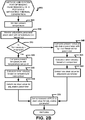
- FIG. 2B is a logical flowchart illustrating a method 205 for optimizing performance of the PCD 100 and while mitigating thermal generation within the PCD 100.
- FIG. 2B tracks the operations presented in FIG. 2A but in a more traditional, linear flow chart format.
- Block 305 is the first block of the method 205.
- the present temperature of a component within the PCD 100 is detected with a temperature sensor 157.
- the dual PID loop controller 205 may be assigned to a single component, such as a CPU 110 or GPU 189.
- a dual PID loop controller 205 may manage/control a plurality of components.
- the temperature monitored in block 305 may be the temperature of the single component.
- a parameter associated with the temperature such as frequency
- the parameter may comprise clock frequency.
- other adjustable parameters associated with temperature may include transmission power of the RF transceiver 168 which includes a modem; data rate or flow rates of the processor 126; as well as other parameters of the PCD 100 which may mitigate thermal generation and that may also impact operating performance of the PCD 100.
- the dual PID loop controller 205 determines if the temperature of a component or component(s) of interest have exceeded a predetermined threshold value.
- This predetermined threshold value may be established at manufacture of the component. For example, the threshold temperature value of a CPU 110 may have magnitude of about 90.0 degrees C. If the inquiry to decision block 315 is positive, then the "YES" branch is followed to block 320. If the inquiry to decision block 315 is negative, then the "NO" branch is followed to block 340.
- the PID controller 221A of loop 209 compares the present measured temperature (sensed in block 305) with the temperature setpoint 218 assigned to the component or components of interest.
- the temperature setpoint 218 may be a fixed value or it may change depending on one or more thermal mitigation algorithms which may be supported by the PCD 100.
- the PID controller 221A of loop 209 in FIG. 2A may calculate an error value (see Te1 of FIG. 2A ) based on the comparison between the temperature setpoint 218 and the present temperature provided by a sensor 157.
- the PID controller 221A of loop 209 may then determine an ideal operating frequency for the CPU 110 (the component of interest) based on the error values and equations EQ1 through EQ3.
- the PID controller 221A of loop 209 may set the component of interest, such as the CPU 110, to the desired operating frequency which minimizes thermal generation by the component of interest which is the CPU 110 in this example.
- the method 205 then returns.
- the PID controller 221B of lower loop 212 compares the present value of the adjustable parameter 224, such as frequency which may be the present clock frequency, with maximum frequency 227 available for the component or components of interest.
- the maximum frequency 227 may be set or it may be dynamic (changeable) depending on thermal mitigation algorithms which may be running in parallel with method 205.
- the PID controller 221B of loop 212 may calculate error value(s) based on the comparison in block 340. Subsequently, the method continues to block 335 where the second PID controller 221B issues commands to the CPU 110 to adjust its operating frequency to the calculated ideal operating frequency. The method 205 then returns.
- the dual PID loop controller 205 is not limited to the adjustable parameter of frequency.
- Other adjustable parameters include, but are not limited to, transmission power of the RF transceiver 168 which includes a modem; data rate or flow rates of the processor 126; as well as other parameters of the PCD 100 which may mitigate thermal generation and that may also impact operating performance of the PCD 100.
- this figure is a functional block diagram of a generic dual PID loop controller 205' for any component within the PCD 100 of FIG. 1 .
- the dual PID loop controller 205' has a first loop 209' and a second loop 212' which are coupled together by a threshold condition 206'.
- the threshold condition 206' may comprise temperature of a component or a plurality of components 301 controlled by the dual PID loop controller 205'.
- Both the first loop 209' and second loop 212' may control as output an adjustable parameter 235', such as, but not limited to, an operating frequency. That adjustable parameter 235' is fed into a single component 301 or a plurality of components 301.
- the first loop 209' of the dual PID loop controller 205' may comprise software, hardware, and/or firmware.
- the second loop 212' of the dual PID loop controller 205' may comprise software, hardware, and/or firmware.
- Each loop 209, 212 may comprise a different structure which means that one loop may comprise software while the second loop comprises hardware, or vice-versa. In other embodiments, each loop 209, 212 may comprise the same structure, i.e. hardware-hardware, software-software, etc.
- both loops 209, 212 may be the most practical design. For example, response times usually must be minimal to detect and to respond to electrical current limitations ("CLs"). For these conditions, both loops 209, 212 may comprise hardware. Exemplary hardware includes, but is not limited to, First-In/First-Out (FIFOs) type devices.
- FIFOs First-In/First-Out
- component 301 may comprise a single component such as a CPU 110, a GPU 189, an analog signal processor 126, a digital signal processor, and other similar/like processing entities as understood by one of ordinary skill in the art.
- the component 301 may also comprise a plurality of devices in some exemplary embodiments instead of a device/component.
- FIG. 4 is a functional block diagram of nested dual PID loop controllers 205A, 205B, 205C that may be present within the PCD of FIG. 1 . This diagram illustrates how multiple dual PID loop controllers 205A, 205B, 205C may be coupled to individual components 301A.
- a first component 301A may be controlled by dual (two) PID loop controllers 205A, 205B.
- a second component 301B may be controlled by dual (two) PID loop controllers 205A, 205C.
- Other ways of nesting/grouping dual PID loop controllers 205A are possible and are included within the scope of this disclosure.
- the dual PID loop controller 205 may maximize performance and reliability: reliability may be maintained by keeping an operating temperature below a setpoint, while performance may be achieved by allowing for a higher operational value once temperature is maintained below desired value.
- the dual PID controller 205 provides a flexible design where the algorithm design may be extended to any component in a PCD 100 - by just varying the controlled and adjustable parameter, such as frequency.
- the dual PID loop controller is adaptable: each of the PID loops 209, 212 may be tuned independently to achieve the level of aggressiveness desired in the control of the component 301. Dual PID loop controllers 205 offer stable operation in most operating conditions. The algorithm of the dual PID loop controllers 205 may achieve quicker convergence to desired temperatures and operational levels compared to single loop control of the conventional art.
- the functions described may be implemented in hardware, software, firmware, or any combination thereof. If implemented in software, the functions may be stored on or transmitted as one or more instructions or code on a computer-readable medium.
- a computer-readable medium is an electronic, magnetic, optical, or other physical device or means that may contain or store a computer program and data for use by or in connection with a computer-related system or method.
- the various logic elements and data stores may be embodied in any computer-readable medium for use by or in connection with an instruction execution system, apparatus, or device, such as a computer-based system, processor-containing system, or other system that can fetch the instructions from the instruction execution system, apparatus, or device and execute the instructions.
- a "computer-readable medium” may include any means that may store, communicate, propagate, or transport the program for use by or in connection with the instruction execution system, apparatus, or device.
- the computer-readable medium can be, for example but not limited to, an electronic, magnetic, optical, electromagnetic, infrared, or semiconductor system, apparatus, device, or propagation medium. More specific examples (a non-exhaustive list) of the computer-readable medium would include the following: an electrical connection (electronic) having one or more wires, a portable computer diskette (magnetic), a random-access memory (RAM) (electronic), a read-only memory (ROM) (electronic), an erasable programmable read-only memory (EPROM, EEPROM, or Flash memory) (electronic), an optical fiber (optical), and a portable compact disc read-only memory (CDROM) (optical).
- an electrical connection having one or more wires
- a portable computer diskette magnetic
- RAM random-access memory
- ROM read-only memory
- EPROM erasable programmable read-only memory
- EPROM erasable programmable read-only memory
- CDROM portable compact disc read-only memory
- the computer-readable medium could even be paper or another suitable medium upon which the program is printed, as the program can be electronically captured, for instance via optical scanning of the paper or other medium, then compiled, interpreted or otherwise processed in a suitable manner if necessary, and then stored in a computer memory.
- Computer-readable media include both computer storage media and communication media including any medium that facilitates transfer of a computer program from one place to another.
- a storage media may be any available media that may be accessed by a computer.
- such computer-readable media may comprise any optical disk storage, magnetic disk storage or other magnetic storage devices, or any other medium that may be used to carry or store desired program code in the form of instructions or data structures and that may be accessed by a computer.
- any connection is properly termed a computer-readable medium.
- the software is transmitted from a website, server, or other remote source using a coaxial cable, fiber optic cable, twisted pair, digital subscriber line ("DSL"), or wireless technologies such as infrared, radio, and microwave
- coaxial cable, fiber optic cable, twisted pair, DSL, or wireless technologies such as infrared, radio, and microwave are included in the definition of medium.
- Disk and disc includes compact disc (“CD”), laser disc, optical disc, digital versatile disc (“DVD”), floppy disk and blu-ray disc where disks usually reproduce data magnetically, while discs reproduce data optically with lasers. Combinations of the above should also be included within the scope of computer-readable media.
- a method for optimizing operation of a portable computing device comprising monitoring temperature of a component within the portable computing device, monitoring a parameter associated with the temperature, determining if the temperature has exceeded a threshold value, if the temperature has exceeded the threshold value, then comparing the temperature with a temperature set point and calculating a first error value based on the comparison, determining a first optimum value of the parameter based on the first error value, if the temperature is below or equal to the threshold value, then comparing a present value of the parameter with a desired threshold for the parameter and calculating a second error value based on the comparison, and determining a second optimum value of the parameter based on the second error value.
- the method may comprise setting the component to at least one of the first and second optimum values.
- the parameter associated with temperature may comprise at least one of operating frequency, transmission power, and a data flow rate.
- the second optimum value for the parameter may be determined by an algorithm. Further, the second optimum value may be set during manufacture of the portable computing device.
- the component may comprise at least one of a central processing unit, a core of a central processing unit, a graphical processing unit, a digital signal processor, a modem, and a RF-transceiver. Further, the method may comprise monitoring and controlling a plurality of components of the portable computing device.
- the plurality of components may comprise one or more of a central processing unit, a core of a central processing unit, a graphical processing unit, a digital signal processor, a modem, and a RF-transceiver.
- the portable computing device may comprise at least one of a mobile telephone, a personal digital assistant, a pager, a smartphone, a navigation device, and a hand-held computer with a wireless connection or link.
- a computer system for optimizing operation of a portable computing device comprising a processor operable for monitoring temperature of a component within the portable computing device, monitoring a parameter associated with the temperature, determining if the temperature has exceeded a threshold value, comparing the temperature with a temperature set point and calculating a first error value based on the comparison if the temperature has exceeded the threshold value, determining a first optimum value of the parameter based on the first error value, comparing a present value of the parameter with a desired threshold for the parameter and calculating a second error value based on the comparison if the temperature is below or equal to the threshold value and determining a second optimum value of the parameter based on the second error value.
- the processor may be operable for setting the component to at least one of the first and second optimum values.
- the parameter associated with temperature may comprise at least one of operating frequency, transmission power, and a data flow rate.
- the second optimum value for the parameter may be determined by an algorithm.
- the second optimum value may be set during manufacture of the portable computing device.
- the component may comprise at least one of a central processing unit, a core of a central processing unit, a graphical processing unit, a digital signal processor, a modem, and a RF-transceiver.
- the processor may be operable for monitoring and controlling a plurality of components of the portable computing device.
- the plurality of components may comprise one or more of a central processing unit, a core of a central processing unit, a graphical processing unit, a digital signal processor, a modem, and a RF-transceiver.
- the portable computing device may comprise at least one of a mobile telephone, a personal digital assistant, a pager, a smartphone, a navigation device, and a hand-held computer with a wireless connection or link.
- a computer system for optimizing operation of a portable computing device comprising means for monitoring temperature of a component within the portable computing device, means for monitoring a parameter associated with the temperature, means for determining if the temperature has exceeded a threshold value, means for comparing the temperature with a temperature set point and calculating a first error value based on the comparison if the temperature has exceeded the threshold value means for determining a first optimum value of the parameter based on the first error value, means for comparing a present value of the parameter with a desired threshold for the parameter and calculating a second error value based on the comparison if the temperature is below or equal to the threshold value, and means for determining a second optimum value of the parameter based on the second error value.
- the system may comprise means for setting the component to at least one of the first and second optimum values.
- the parameter associated with temperature may comprise at least one of operating frequency, transmission power, and a data flow rate.
- the second optimum value for the parameter may be determined by an algorithm.
- the second optimum value may be set during manufacture of the portable computing device.
- a computer program product comprising a computer usable medium having a computer readable program code embodied therein, said computer readable program code adapted to be executed to implement a method for optimizing operation of a portable computing device, said method comprising monitoring temperature of a component within the portable computing device, monitoring a parameter associated with the temperature, determining if the temperature has exceeded a threshold value, if the temperature has exceeded the threshold value, then comparing the temperature with a temperature set point and calculating a first error value based on the comparison, determining a first optimum value of the parameter based on the first error value, if the temperature is below or equal to the threshold value, then comparing a present value of the parameter with a desired threshold for the parameter and calculating a second error value based on the comparison, and determining a second optimum value of the parameter based on the second error value.
- the program code implementing the method may comprise setting the component to at least one of the first and second optimum values.
- the parameter associated with temperature may comprise at least one of operating frequency, transmission power, and a data flow rate.
- the second optimum value for the parameter may determined by an algorithm. Further, the second optimum value may be set during manufacture of the portable computing device.
- the component may comprise at least one of a central processing unit, a core of a central processing unit, a graphical processing unit, a digital signal processor, a modem, and a RF-transceiver.
- the portable computing device may comprise at least one of a mobile telephone, a personal digital assistant, a pager, a smartphone, a navigation device, and a hand-held computer with a wireless connection or link.
Landscapes
- Engineering & Computer Science (AREA)
- Theoretical Computer Science (AREA)
- Physics & Mathematics (AREA)
- General Physics & Mathematics (AREA)
- General Engineering & Computer Science (AREA)
- Human Computer Interaction (AREA)
- Computer Hardware Design (AREA)
- Automation & Control Theory (AREA)
- Condensed Matter Physics & Semiconductors (AREA)
- Microelectronics & Electronic Packaging (AREA)
- Power Engineering (AREA)
- Power Sources (AREA)
- Feedback Control In General (AREA)
- Telephone Function (AREA)
Applications Claiming Priority (3)
| Application Number | Priority Date | Filing Date | Title |
|---|---|---|---|
| US201461973772P | 2014-04-01 | 2014-04-01 | |
| US14/289,675 US10082847B2 (en) | 2014-04-01 | 2014-05-29 | Method and system for optimizing performance of a PCD while mitigating thermal generation |
| PCT/US2015/023638 WO2015153643A1 (en) | 2014-04-01 | 2015-03-31 | Method and system for optimizing performance of a pcd while mitigating thermal generation |
Publications (2)
| Publication Number | Publication Date |
|---|---|
| EP3126927A1 EP3126927A1 (en) | 2017-02-08 |
| EP3126927B1 true EP3126927B1 (en) | 2019-10-30 |
Family
ID=54190210
Family Applications (1)
| Application Number | Title | Priority Date | Filing Date |
|---|---|---|---|
| EP15716353.6A Active EP3126927B1 (en) | 2014-04-01 | 2015-03-31 | Method and system for optimizing performance of a pcd while mitigating thermal generation |
Country Status (6)
| Country | Link |
|---|---|
| US (1) | US10082847B2 (enExample) |
| EP (1) | EP3126927B1 (enExample) |
| JP (1) | JP2017513393A (enExample) |
| KR (1) | KR20160138479A (enExample) |
| CN (1) | CN106537282B (enExample) |
| WO (1) | WO2015153643A1 (enExample) |
Families Citing this family (10)
| Publication number | Priority date | Publication date | Assignee | Title |
|---|---|---|---|---|
| US9791904B2 (en) * | 2014-08-15 | 2017-10-17 | Intel Corporation | Balanced control of processor temperature |
| US10114432B2 (en) * | 2014-12-29 | 2018-10-30 | Mediatek Inc. | Thermal control system and thermal control method for electronic device |
| US10216246B2 (en) * | 2016-09-30 | 2019-02-26 | Intel Corporation | Multi-level loops for computer processor control |
| KR102643797B1 (ko) * | 2017-01-10 | 2024-03-05 | 삼성전자주식회사 | 동적 발열 관리 방법 |
| CN107506010A (zh) * | 2017-08-25 | 2017-12-22 | 深圳天珑无线科技有限公司 | 一种温度控制方法、装置及计算机可读存储介质 |
| CN110113479B (zh) * | 2019-04-15 | 2020-10-30 | 珠海格力电器股份有限公司 | 智能终端降温策略的制定方法、降温方法、系统、终端 |
| CN110836197B (zh) * | 2019-11-05 | 2021-05-25 | 英业达科技有限公司 | 一种能耗自动优化的策略 |
| EP4485136A4 (en) * | 2022-07-19 | 2025-06-25 | Samsung Electronics Co., Ltd | Method and device for controlling heat caused by electronic device on basis of pid controller |
| CN118795761A (zh) * | 2024-03-27 | 2024-10-18 | 中国移动通信集团设计院有限公司 | 数据中心机房智能温控方法、系统、电子设备及存储介质 |
| CN120353122B (zh) * | 2025-06-16 | 2025-08-29 | 山东泰开检测有限公司 | 一种气体试验变压器的水冷控制方法、终端及存储介质 |
Citations (2)
| Publication number | Priority date | Publication date | Assignee | Title |
|---|---|---|---|---|
| US20090006901A1 (en) * | 2007-06-28 | 2009-01-01 | International Business Machines Corporation | Control Systems and Method Using a Shared Component Actuator |
| US20130035797A1 (en) * | 2011-08-01 | 2013-02-07 | International Business Machines Corporation | Performance of digital circuits using current management |
Family Cites Families (29)
| Publication number | Priority date | Publication date | Assignee | Title |
|---|---|---|---|---|
| JP3028448B2 (ja) * | 1992-05-08 | 2000-04-04 | 東京エレクトロン株式会社 | 制御システム |
| US7216064B1 (en) | 1993-09-21 | 2007-05-08 | Intel Corporation | Method and apparatus for programmable thermal sensor for an integrated circuit |
| US6110289A (en) * | 1997-02-25 | 2000-08-29 | Moore Epitaxial, Inc. | Rapid thermal processing barrel reactor for processing substrates |
| US6415388B1 (en) * | 1998-10-30 | 2002-07-02 | Intel Corporation | Method and apparatus for power throttling in a microprocessor using a closed loop feedback system |
| US6783080B2 (en) * | 2002-05-16 | 2004-08-31 | Advanced Thermal Sciences Corp. | Systems and methods for controlling temperatures of process tools |
| JP3805344B2 (ja) * | 2004-06-22 | 2006-08-02 | 株式会社ソニー・コンピュータエンタテインメント | プロセッサ、情報処理装置およびプロセッサの制御方法 |
| US8374730B2 (en) * | 2005-08-25 | 2013-02-12 | Apple Inc. | Methods and apparatuses for dynamic thermal control |
| US7263457B2 (en) * | 2006-01-03 | 2007-08-28 | Advanced Micro Devices, Inc. | System and method for operating components of an integrated circuit at independent frequencies and/or voltages |
| JP4778318B2 (ja) * | 2006-01-20 | 2011-09-21 | 富士通東芝モバイルコミュニケーションズ株式会社 | 携帯端末 |
| US8762097B2 (en) * | 2006-08-04 | 2014-06-24 | Apple Inc. | Method and apparatus for a thermal control system based on virtual temperature sensor |
| US8515095B2 (en) | 2007-10-04 | 2013-08-20 | Apple Inc. | Reducing annoyance by managing the acoustic noise produced by a device |
| US8315746B2 (en) * | 2008-05-30 | 2012-11-20 | Apple Inc. | Thermal management techniques in an electronic device |
| US8170606B2 (en) * | 2008-10-15 | 2012-05-01 | Apple Inc. | Dynamic thermal control for wireless transceivers |
| JP4966292B2 (ja) * | 2008-12-25 | 2012-07-04 | 株式会社東芝 | 情報処理装置および冷却性能判定方法 |
| US8392340B2 (en) * | 2009-03-13 | 2013-03-05 | Apple Inc. | Method and apparatus for detecting conditions of a peripheral device including motion, and determining/predicting temperature(S) wherein at least one temperature is weighted based on detected conditions |
| EP2400368B1 (en) * | 2010-06-24 | 2020-03-18 | BlackBerry Limited | Power cut-off based on current |
| US8942857B2 (en) * | 2011-04-22 | 2015-01-27 | Qualcomm Incorporated | Method and system for thermal load management in a portable computing device |
| US9207730B2 (en) | 2011-06-02 | 2015-12-08 | Apple Inc. | Multi-level thermal management in an electronic device |
| KR101894282B1 (ko) * | 2011-07-29 | 2018-09-03 | 삼성전자 주식회사 | 단말기 온도 제어 방법 및 이를 지원하는 단말기 |
| US8970234B2 (en) | 2011-09-26 | 2015-03-03 | Apple Inc. | Threshold-based temperature-dependent power/thermal management with temperature sensor calibration |
| TWI467354B (zh) * | 2011-09-30 | 2015-01-01 | Quanta Comp Inc | 電子裝置與溫度調節方法 |
| US8994339B1 (en) * | 2012-02-09 | 2015-03-31 | Google Inc. | Battery temperature compensation with closed-loop fan control |
| US20130228632A1 (en) * | 2012-03-02 | 2013-09-05 | Apple Inc. | Controlling a cooling system for a computer system |
| CN102591382B (zh) * | 2012-03-14 | 2018-02-27 | 中兴通讯股份有限公司 | 温度控制装置、方法与电子设备 |
| CN103376859B (zh) * | 2012-04-26 | 2016-12-14 | 华为技术有限公司 | 芯片性能的控制方法及装置 |
| US9250665B2 (en) | 2012-06-07 | 2016-02-02 | Apple Inc. | GPU with dynamic performance adjustment |
| US8972759B2 (en) | 2012-06-29 | 2015-03-03 | Qualcomm Incorporated | Adaptive thermal management in a portable computing device including monitoring a temperature signal and holding a performance level during a penalty period |
| US9665141B2 (en) * | 2013-06-05 | 2017-05-30 | Apple Inc. | Thermal management of an integrated circuit |
| US20150075186A1 (en) * | 2013-09-18 | 2015-03-19 | Qualcomm Incorporated | Method of and an apparatus for maintaining constant phone skin temperature with a thermoelectric cooler and increasing allowable power/performance limit for die in a mobile segment |
-
2014
- 2014-05-29 US US14/289,675 patent/US10082847B2/en active Active
-
2015
- 2015-03-31 CN CN201580017553.0A patent/CN106537282B/zh active Active
- 2015-03-31 EP EP15716353.6A patent/EP3126927B1/en active Active
- 2015-03-31 WO PCT/US2015/023638 patent/WO2015153643A1/en not_active Ceased
- 2015-03-31 KR KR1020167029457A patent/KR20160138479A/ko not_active Withdrawn
- 2015-03-31 JP JP2016559577A patent/JP2017513393A/ja active Pending
Patent Citations (2)
| Publication number | Priority date | Publication date | Assignee | Title |
|---|---|---|---|---|
| US20090006901A1 (en) * | 2007-06-28 | 2009-01-01 | International Business Machines Corporation | Control Systems and Method Using a Shared Component Actuator |
| US20130035797A1 (en) * | 2011-08-01 | 2013-02-07 | International Business Machines Corporation | Performance of digital circuits using current management |
Also Published As
| Publication number | Publication date |
|---|---|
| JP2017513393A (ja) | 2017-05-25 |
| CN106537282B (zh) | 2019-11-19 |
| KR20160138479A (ko) | 2016-12-05 |
| US20150277395A1 (en) | 2015-10-01 |
| EP3126927A1 (en) | 2017-02-08 |
| WO2015153643A1 (en) | 2015-10-08 |
| US10082847B2 (en) | 2018-09-25 |
| CN106537282A (zh) | 2017-03-22 |
Similar Documents
| Publication | Publication Date | Title |
|---|---|---|
| EP3126927B1 (en) | Method and system for optimizing performance of a pcd while mitigating thermal generation | |
| EP2962169B1 (en) | System and method for thermal management in a portable computing device using thermal resistance values to predict optimum power levels | |
| CN108780349B (zh) | 用于在具有异构集群架构的片上系统中进行智能热管理的系统和方法 | |
| US20160070327A1 (en) | System and method for peak current management to a system on a chip | |
| US10037258B2 (en) | System and method for intelligent thermal management using dynamic performance floors in a portable computing device | |
| US9116677B2 (en) | System and method for managing a thermal policy of a receiving device that couples to a portable computing device | |
| US9329663B2 (en) | Processor power and performance manager | |
| EP3022627A1 (en) | System and method for idle state optimization in a multi-processor system on a chip | |
| CN106062653A (zh) | 用于控制电流的方法和电子设备 | |
| EP3571568B1 (en) | System and method for context-aware thermal management and workload scheduling in a portable computing device | |
| US10305292B2 (en) | Methods, apparatus, systems and articles of manufacture to charge a battery based on an electronic device skin temperature | |
| US20140245028A1 (en) | System and method for temperature driven selection of voltage modes in a portable computing device | |
| CN105824377A (zh) | 一种系统温度控制方法和移动终端 | |
| CN106708218B (zh) | 一种风扇的防噪控制方法及装置 | |
| US20150185803A1 (en) | System and method for dcvs headroom adjustment and processing level optimization in a system on a chip | |
| JP2014059866A (ja) | エネルギーを節約しつつデータを連続配信する技術 | |
| US20160224080A1 (en) | Calibration margin optimization in a multi-processor system on a chip | |
| WO2016165372A1 (zh) | 控制移动终端中cpu的热插拔操作的方法和装置 | |
| WO2017075991A1 (zh) | 一种ota升级模式下的功耗控制方法及系统 | |
| WO2016127611A1 (zh) | 一种可控风扇的调速方法及装置 |
Legal Events
| Date | Code | Title | Description |
|---|---|---|---|
| STAA | Information on the status of an ep patent application or granted ep patent |
Free format text: STATUS: THE INTERNATIONAL PUBLICATION HAS BEEN MADE |
|
| PUAI | Public reference made under article 153(3) epc to a published international application that has entered the european phase |
Free format text: ORIGINAL CODE: 0009012 |
|
| STAA | Information on the status of an ep patent application or granted ep patent |
Free format text: STATUS: REQUEST FOR EXAMINATION WAS MADE |
|
| 17P | Request for examination filed |
Effective date: 20160908 |
|
| AK | Designated contracting states |
Kind code of ref document: A1 Designated state(s): AL AT BE BG CH CY CZ DE DK EE ES FI FR GB GR HR HU IE IS IT LI LT LU LV MC MK MT NL NO PL PT RO RS SE SI SK SM TR |
|
| AX | Request for extension of the european patent |
Extension state: BA ME |
|
| DAV | Request for validation of the european patent (deleted) | ||
| DAX | Request for extension of the european patent (deleted) | ||
| STAA | Information on the status of an ep patent application or granted ep patent |
Free format text: STATUS: EXAMINATION IS IN PROGRESS |
|
| 17Q | First examination report despatched |
Effective date: 20180117 |
|
| REG | Reference to a national code |
Ref country code: DE Ref legal event code: R079 Ref document number: 602015040678 Country of ref document: DE Free format text: PREVIOUS MAIN CLASS: G06F0001200000 Ipc: G06F0001324000 |
|
| GRAP | Despatch of communication of intention to grant a patent |
Free format text: ORIGINAL CODE: EPIDOSNIGR1 |
|
| STAA | Information on the status of an ep patent application or granted ep patent |
Free format text: STATUS: GRANT OF PATENT IS INTENDED |
|
| RIC1 | Information provided on ipc code assigned before grant |
Ipc: G06F 1/324 20190101AFI20190524BHEP Ipc: G06F 1/3203 20190101ALI20190524BHEP Ipc: G06F 1/20 20060101ALI20190524BHEP |
|
| INTG | Intention to grant announced |
Effective date: 20190617 |
|
| GRAS | Grant fee paid |
Free format text: ORIGINAL CODE: EPIDOSNIGR3 |
|
| GRAA | (expected) grant |
Free format text: ORIGINAL CODE: 0009210 |
|
| STAA | Information on the status of an ep patent application or granted ep patent |
Free format text: STATUS: THE PATENT HAS BEEN GRANTED |
|
| AK | Designated contracting states |
Kind code of ref document: B1 Designated state(s): AL AT BE BG CH CY CZ DE DK EE ES FI FR GB GR HR HU IE IS IT LI LT LU LV MC MK MT NL NO PL PT RO RS SE SI SK SM TR |
|
| REG | Reference to a national code |
Ref country code: GB Ref legal event code: FG4D |
|
| REG | Reference to a national code |
Ref country code: CH Ref legal event code: EP |
|
| REG | Reference to a national code |
Ref country code: AT Ref legal event code: REF Ref document number: 1196840 Country of ref document: AT Kind code of ref document: T Effective date: 20191115 |
|
| REG | Reference to a national code |
Ref country code: DE Ref legal event code: R096 Ref document number: 602015040678 Country of ref document: DE |
|
| REG | Reference to a national code |
Ref country code: IE Ref legal event code: FG4D |
|
| REG | Reference to a national code |
Ref country code: LT Ref legal event code: MG4D |
|
| PG25 | Lapsed in a contracting state [announced via postgrant information from national office to epo] |
Ref country code: NL Free format text: LAPSE BECAUSE OF FAILURE TO SUBMIT A TRANSLATION OF THE DESCRIPTION OR TO PAY THE FEE WITHIN THE PRESCRIBED TIME-LIMIT Effective date: 20191030 Ref country code: LV Free format text: LAPSE BECAUSE OF FAILURE TO SUBMIT A TRANSLATION OF THE DESCRIPTION OR TO PAY THE FEE WITHIN THE PRESCRIBED TIME-LIMIT Effective date: 20191030 Ref country code: SE Free format text: LAPSE BECAUSE OF FAILURE TO SUBMIT A TRANSLATION OF THE DESCRIPTION OR TO PAY THE FEE WITHIN THE PRESCRIBED TIME-LIMIT Effective date: 20191030 Ref country code: PL Free format text: LAPSE BECAUSE OF FAILURE TO SUBMIT A TRANSLATION OF THE DESCRIPTION OR TO PAY THE FEE WITHIN THE PRESCRIBED TIME-LIMIT Effective date: 20191030 Ref country code: PT Free format text: LAPSE BECAUSE OF FAILURE TO SUBMIT A TRANSLATION OF THE DESCRIPTION OR TO PAY THE FEE WITHIN THE PRESCRIBED TIME-LIMIT Effective date: 20200302 Ref country code: BG Free format text: LAPSE BECAUSE OF FAILURE TO SUBMIT A TRANSLATION OF THE DESCRIPTION OR TO PAY THE FEE WITHIN THE PRESCRIBED TIME-LIMIT Effective date: 20200130 Ref country code: FI Free format text: LAPSE BECAUSE OF FAILURE TO SUBMIT A TRANSLATION OF THE DESCRIPTION OR TO PAY THE FEE WITHIN THE PRESCRIBED TIME-LIMIT Effective date: 20191030 Ref country code: GR Free format text: LAPSE BECAUSE OF FAILURE TO SUBMIT A TRANSLATION OF THE DESCRIPTION OR TO PAY THE FEE WITHIN THE PRESCRIBED TIME-LIMIT Effective date: 20200131 Ref country code: NO Free format text: LAPSE BECAUSE OF FAILURE TO SUBMIT A TRANSLATION OF THE DESCRIPTION OR TO PAY THE FEE WITHIN THE PRESCRIBED TIME-LIMIT Effective date: 20200130 Ref country code: LT Free format text: LAPSE BECAUSE OF FAILURE TO SUBMIT A TRANSLATION OF THE DESCRIPTION OR TO PAY THE FEE WITHIN THE PRESCRIBED TIME-LIMIT Effective date: 20191030 |
|
| PGFP | Annual fee paid to national office [announced via postgrant information from national office to epo] |
Ref country code: GB Payment date: 20200228 Year of fee payment: 6 |
|
| REG | Reference to a national code |
Ref country code: NL Ref legal event code: MP Effective date: 20191030 |
|
| PG25 | Lapsed in a contracting state [announced via postgrant information from national office to epo] |
Ref country code: HR Free format text: LAPSE BECAUSE OF FAILURE TO SUBMIT A TRANSLATION OF THE DESCRIPTION OR TO PAY THE FEE WITHIN THE PRESCRIBED TIME-LIMIT Effective date: 20191030 Ref country code: RS Free format text: LAPSE BECAUSE OF FAILURE TO SUBMIT A TRANSLATION OF THE DESCRIPTION OR TO PAY THE FEE WITHIN THE PRESCRIBED TIME-LIMIT Effective date: 20191030 Ref country code: IS Free format text: LAPSE BECAUSE OF FAILURE TO SUBMIT A TRANSLATION OF THE DESCRIPTION OR TO PAY THE FEE WITHIN THE PRESCRIBED TIME-LIMIT Effective date: 20200229 |
|
| PG25 | Lapsed in a contracting state [announced via postgrant information from national office to epo] |
Ref country code: AL Free format text: LAPSE BECAUSE OF FAILURE TO SUBMIT A TRANSLATION OF THE DESCRIPTION OR TO PAY THE FEE WITHIN THE PRESCRIBED TIME-LIMIT Effective date: 20191030 |
|
| PGFP | Annual fee paid to national office [announced via postgrant information from national office to epo] |
Ref country code: FR Payment date: 20200312 Year of fee payment: 6 |
|
| PG25 | Lapsed in a contracting state [announced via postgrant information from national office to epo] |
Ref country code: CZ Free format text: LAPSE BECAUSE OF FAILURE TO SUBMIT A TRANSLATION OF THE DESCRIPTION OR TO PAY THE FEE WITHIN THE PRESCRIBED TIME-LIMIT Effective date: 20191030 Ref country code: ES Free format text: LAPSE BECAUSE OF FAILURE TO SUBMIT A TRANSLATION OF THE DESCRIPTION OR TO PAY THE FEE WITHIN THE PRESCRIBED TIME-LIMIT Effective date: 20191030 Ref country code: RO Free format text: LAPSE BECAUSE OF FAILURE TO SUBMIT A TRANSLATION OF THE DESCRIPTION OR TO PAY THE FEE WITHIN THE PRESCRIBED TIME-LIMIT Effective date: 20191030 Ref country code: DK Free format text: LAPSE BECAUSE OF FAILURE TO SUBMIT A TRANSLATION OF THE DESCRIPTION OR TO PAY THE FEE WITHIN THE PRESCRIBED TIME-LIMIT Effective date: 20191030 Ref country code: EE Free format text: LAPSE BECAUSE OF FAILURE TO SUBMIT A TRANSLATION OF THE DESCRIPTION OR TO PAY THE FEE WITHIN THE PRESCRIBED TIME-LIMIT Effective date: 20191030 |
|
| REG | Reference to a national code |
Ref country code: DE Ref legal event code: R097 Ref document number: 602015040678 Country of ref document: DE |
|
| REG | Reference to a national code |
Ref country code: AT Ref legal event code: MK05 Ref document number: 1196840 Country of ref document: AT Kind code of ref document: T Effective date: 20191030 |
|
| PG25 | Lapsed in a contracting state [announced via postgrant information from national office to epo] |
Ref country code: IT Free format text: LAPSE BECAUSE OF FAILURE TO SUBMIT A TRANSLATION OF THE DESCRIPTION OR TO PAY THE FEE WITHIN THE PRESCRIBED TIME-LIMIT Effective date: 20191030 Ref country code: SM Free format text: LAPSE BECAUSE OF FAILURE TO SUBMIT A TRANSLATION OF THE DESCRIPTION OR TO PAY THE FEE WITHIN THE PRESCRIBED TIME-LIMIT Effective date: 20191030 Ref country code: SK Free format text: LAPSE BECAUSE OF FAILURE TO SUBMIT A TRANSLATION OF THE DESCRIPTION OR TO PAY THE FEE WITHIN THE PRESCRIBED TIME-LIMIT Effective date: 20191030 |
|
| PLBE | No opposition filed within time limit |
Free format text: ORIGINAL CODE: 0009261 |
|
| STAA | Information on the status of an ep patent application or granted ep patent |
Free format text: STATUS: NO OPPOSITION FILED WITHIN TIME LIMIT |
|
| 26N | No opposition filed |
Effective date: 20200731 |
|
| PG25 | Lapsed in a contracting state [announced via postgrant information from national office to epo] |
Ref country code: MC Free format text: LAPSE BECAUSE OF FAILURE TO SUBMIT A TRANSLATION OF THE DESCRIPTION OR TO PAY THE FEE WITHIN THE PRESCRIBED TIME-LIMIT Effective date: 20191030 |
|
| REG | Reference to a national code |
Ref country code: CH Ref legal event code: PL |
|
| PG25 | Lapsed in a contracting state [announced via postgrant information from national office to epo] |
Ref country code: AT Free format text: LAPSE BECAUSE OF FAILURE TO SUBMIT A TRANSLATION OF THE DESCRIPTION OR TO PAY THE FEE WITHIN THE PRESCRIBED TIME-LIMIT Effective date: 20191030 Ref country code: SI Free format text: LAPSE BECAUSE OF FAILURE TO SUBMIT A TRANSLATION OF THE DESCRIPTION OR TO PAY THE FEE WITHIN THE PRESCRIBED TIME-LIMIT Effective date: 20191030 |
|
| REG | Reference to a national code |
Ref country code: BE Ref legal event code: MM Effective date: 20200331 |
|
| PG25 | Lapsed in a contracting state [announced via postgrant information from national office to epo] |
Ref country code: LU Free format text: LAPSE BECAUSE OF NON-PAYMENT OF DUE FEES Effective date: 20200331 |
|
| PG25 | Lapsed in a contracting state [announced via postgrant information from national office to epo] |
Ref country code: IE Free format text: LAPSE BECAUSE OF NON-PAYMENT OF DUE FEES Effective date: 20200331 Ref country code: LI Free format text: LAPSE BECAUSE OF NON-PAYMENT OF DUE FEES Effective date: 20200331 Ref country code: CH Free format text: LAPSE BECAUSE OF NON-PAYMENT OF DUE FEES Effective date: 20200331 |
|
| PG25 | Lapsed in a contracting state [announced via postgrant information from national office to epo] |
Ref country code: BE Free format text: LAPSE BECAUSE OF NON-PAYMENT OF DUE FEES Effective date: 20200331 |
|
| GBPC | Gb: european patent ceased through non-payment of renewal fee |
Effective date: 20210331 |
|
| PG25 | Lapsed in a contracting state [announced via postgrant information from national office to epo] |
Ref country code: GB Free format text: LAPSE BECAUSE OF NON-PAYMENT OF DUE FEES Effective date: 20210331 Ref country code: FR Free format text: LAPSE BECAUSE OF NON-PAYMENT OF DUE FEES Effective date: 20210331 |
|
| PG25 | Lapsed in a contracting state [announced via postgrant information from national office to epo] |
Ref country code: TR Free format text: LAPSE BECAUSE OF FAILURE TO SUBMIT A TRANSLATION OF THE DESCRIPTION OR TO PAY THE FEE WITHIN THE PRESCRIBED TIME-LIMIT Effective date: 20191030 Ref country code: MT Free format text: LAPSE BECAUSE OF FAILURE TO SUBMIT A TRANSLATION OF THE DESCRIPTION OR TO PAY THE FEE WITHIN THE PRESCRIBED TIME-LIMIT Effective date: 20191030 Ref country code: CY Free format text: LAPSE BECAUSE OF FAILURE TO SUBMIT A TRANSLATION OF THE DESCRIPTION OR TO PAY THE FEE WITHIN THE PRESCRIBED TIME-LIMIT Effective date: 20191030 |
|
| PG25 | Lapsed in a contracting state [announced via postgrant information from national office to epo] |
Ref country code: MK Free format text: LAPSE BECAUSE OF FAILURE TO SUBMIT A TRANSLATION OF THE DESCRIPTION OR TO PAY THE FEE WITHIN THE PRESCRIBED TIME-LIMIT Effective date: 20191030 |
|
| PGFP | Annual fee paid to national office [announced via postgrant information from national office to epo] |
Ref country code: DE Payment date: 20250210 Year of fee payment: 11 |