EP3125802B1 - Cathéter d'ablation et appareil d'ablation - Google Patents
Cathéter d'ablation et appareil d'ablation Download PDFInfo
- Publication number
- EP3125802B1 EP3125802B1 EP15718091.0A EP15718091A EP3125802B1 EP 3125802 B1 EP3125802 B1 EP 3125802B1 EP 15718091 A EP15718091 A EP 15718091A EP 3125802 B1 EP3125802 B1 EP 3125802B1
- Authority
- EP
- European Patent Office
- Prior art keywords
- ablation
- catheter
- petal
- tubular body
- head
- Prior art date
- Legal status (The legal status is an assumption and is not a legal conclusion. Google has not performed a legal analysis and makes no representation as to the accuracy of the status listed.)
- Active
Links
- 238000002679 ablation Methods 0.000 title claims description 142
- 239000004020 conductor Substances 0.000 claims description 47
- 238000007674 radiofrequency ablation Methods 0.000 claims description 6
- RVTZCBVAJQQJTK-UHFFFAOYSA-N oxygen(2-);zirconium(4+) Chemical compound [O-2].[O-2].[Zr+4] RVTZCBVAJQQJTK-UHFFFAOYSA-N 0.000 claims description 3
- 230000002093 peripheral effect Effects 0.000 claims description 3
- 238000001514 detection method Methods 0.000 claims description 2
- 239000012777 electrically insulating material Substances 0.000 claims description 2
- 239000003973 paint Substances 0.000 claims description 2
- 238000011282 treatment Methods 0.000 description 31
- 210000003462 vein Anatomy 0.000 description 18
- 230000008901 benefit Effects 0.000 description 11
- 206010003658 Atrial Fibrillation Diseases 0.000 description 5
- 208000027418 Wounds and injury Diseases 0.000 description 5
- 230000006378 damage Effects 0.000 description 5
- 238000011298 ablation treatment Methods 0.000 description 4
- 238000003780 insertion Methods 0.000 description 4
- 239000000463 material Substances 0.000 description 4
- HLXZNVUGXRDIFK-UHFFFAOYSA-N nickel titanium Chemical compound [Ti].[Ti].[Ti].[Ti].[Ti].[Ti].[Ti].[Ti].[Ti].[Ti].[Ti].[Ni].[Ni].[Ni].[Ni].[Ni].[Ni].[Ni].[Ni].[Ni].[Ni].[Ni].[Ni].[Ni].[Ni] HLXZNVUGXRDIFK-UHFFFAOYSA-N 0.000 description 4
- 229910001000 nickel titanium Inorganic materials 0.000 description 4
- 230000002035 prolonged effect Effects 0.000 description 4
- 210000003492 pulmonary vein Anatomy 0.000 description 4
- 230000015572 biosynthetic process Effects 0.000 description 3
- 230000000694 effects Effects 0.000 description 3
- 208000014674 injury Diseases 0.000 description 3
- 230000037431 insertion Effects 0.000 description 3
- 239000002184 metal Substances 0.000 description 3
- 229910052751 metal Inorganic materials 0.000 description 3
- 238000000034 method Methods 0.000 description 3
- RYGMFSIKBFXOCR-UHFFFAOYSA-N Copper Chemical compound [Cu] RYGMFSIKBFXOCR-UHFFFAOYSA-N 0.000 description 2
- 230000009471 action Effects 0.000 description 2
- 230000003213 activating effect Effects 0.000 description 2
- 238000013459 approach Methods 0.000 description 2
- 239000008280 blood Substances 0.000 description 2
- 210000004369 blood Anatomy 0.000 description 2
- 238000010276 construction Methods 0.000 description 2
- 229910052802 copper Inorganic materials 0.000 description 2
- 239000010949 copper Substances 0.000 description 2
- 238000000605 extraction Methods 0.000 description 2
- 239000012530 fluid Substances 0.000 description 2
- 238000010438 heat treatment Methods 0.000 description 2
- 238000013507 mapping Methods 0.000 description 2
- 238000012986 modification Methods 0.000 description 2
- 230000004048 modification Effects 0.000 description 2
- 230000017074 necrotic cell death Effects 0.000 description 2
- 230000009467 reduction Effects 0.000 description 2
- 206010020772 Hypertension Diseases 0.000 description 1
- 241001465754 Metazoa Species 0.000 description 1
- 206010039897 Sedation Diseases 0.000 description 1
- 208000007536 Thrombosis Diseases 0.000 description 1
- 230000004913 activation Effects 0.000 description 1
- 210000001367 artery Anatomy 0.000 description 1
- 238000005452 bending Methods 0.000 description 1
- 210000004204 blood vessel Anatomy 0.000 description 1
- 239000011248 coating agent Substances 0.000 description 1
- 238000000576 coating method Methods 0.000 description 1
- 230000001427 coherent effect Effects 0.000 description 1
- 230000001276 controlling effect Effects 0.000 description 1
- 230000001419 dependent effect Effects 0.000 description 1
- 210000003191 femoral vein Anatomy 0.000 description 1
- 210000002837 heart atrium Anatomy 0.000 description 1
- 238000002955 isolation Methods 0.000 description 1
- 230000003902 lesion Effects 0.000 description 1
- 238000004137 mechanical activation Methods 0.000 description 1
- 229910001092 metal group alloy Inorganic materials 0.000 description 1
- 150000002739 metals Chemical class 0.000 description 1
- 230000002956 necrotizing effect Effects 0.000 description 1
- 230000010355 oscillation Effects 0.000 description 1
- 230000008569 process Effects 0.000 description 1
- 208000002815 pulmonary hypertension Diseases 0.000 description 1
- 230000001105 regulatory effect Effects 0.000 description 1
- 210000002254 renal artery Anatomy 0.000 description 1
- 230000000284 resting effect Effects 0.000 description 1
- 230000001020 rhythmical effect Effects 0.000 description 1
- 230000036280 sedation Effects 0.000 description 1
- 238000004904 shortening Methods 0.000 description 1
- 239000007787 solid Substances 0.000 description 1
- 238000012800 visualization Methods 0.000 description 1
Images


Classifications
-
- A—HUMAN NECESSITIES
- A61—MEDICAL OR VETERINARY SCIENCE; HYGIENE
- A61B—DIAGNOSIS; SURGERY; IDENTIFICATION
- A61B18/00—Surgical instruments, devices or methods for transferring non-mechanical forms of energy to or from the body
- A61B18/04—Surgical instruments, devices or methods for transferring non-mechanical forms of energy to or from the body by heating
- A61B18/12—Surgical instruments, devices or methods for transferring non-mechanical forms of energy to or from the body by heating by passing a current through the tissue to be heated, e.g. high-frequency current
- A61B18/14—Probes or electrodes therefor
- A61B18/1492—Probes or electrodes therefor having a flexible, catheter-like structure, e.g. for heart ablation
-
- A—HUMAN NECESSITIES
- A61—MEDICAL OR VETERINARY SCIENCE; HYGIENE
- A61B—DIAGNOSIS; SURGERY; IDENTIFICATION
- A61B18/00—Surgical instruments, devices or methods for transferring non-mechanical forms of energy to or from the body
- A61B18/04—Surgical instruments, devices or methods for transferring non-mechanical forms of energy to or from the body by heating
- A61B18/12—Surgical instruments, devices or methods for transferring non-mechanical forms of energy to or from the body by heating by passing a current through the tissue to be heated, e.g. high-frequency current
- A61B18/1206—Generators therefor
-
- A—HUMAN NECESSITIES
- A61—MEDICAL OR VETERINARY SCIENCE; HYGIENE
- A61B—DIAGNOSIS; SURGERY; IDENTIFICATION
- A61B18/00—Surgical instruments, devices or methods for transferring non-mechanical forms of energy to or from the body
- A61B2018/00053—Mechanical features of the instrument of device
- A61B2018/0016—Energy applicators arranged in a two- or three dimensional array
-
- A—HUMAN NECESSITIES
- A61—MEDICAL OR VETERINARY SCIENCE; HYGIENE
- A61B—DIAGNOSIS; SURGERY; IDENTIFICATION
- A61B18/00—Surgical instruments, devices or methods for transferring non-mechanical forms of energy to or from the body
- A61B2018/00053—Mechanical features of the instrument of device
- A61B2018/00214—Expandable means emitting energy, e.g. by elements carried thereon
- A61B2018/00267—Expandable means emitting energy, e.g. by elements carried thereon having a basket shaped structure
-
- A—HUMAN NECESSITIES
- A61—MEDICAL OR VETERINARY SCIENCE; HYGIENE
- A61B—DIAGNOSIS; SURGERY; IDENTIFICATION
- A61B18/00—Surgical instruments, devices or methods for transferring non-mechanical forms of energy to or from the body
- A61B2018/00053—Mechanical features of the instrument of device
- A61B2018/00273—Anchoring means for temporary attachment of a device to tissue
- A61B2018/00279—Anchoring means for temporary attachment of a device to tissue deployable
- A61B2018/00285—Balloons
-
- A—HUMAN NECESSITIES
- A61—MEDICAL OR VETERINARY SCIENCE; HYGIENE
- A61B—DIAGNOSIS; SURGERY; IDENTIFICATION
- A61B18/00—Surgical instruments, devices or methods for transferring non-mechanical forms of energy to or from the body
- A61B2018/00315—Surgical instruments, devices or methods for transferring non-mechanical forms of energy to or from the body for treatment of particular body parts
- A61B2018/00345—Vascular system
- A61B2018/00351—Heart
- A61B2018/00375—Ostium, e.g. ostium of pulmonary vein or artery
-
- A—HUMAN NECESSITIES
- A61—MEDICAL OR VETERINARY SCIENCE; HYGIENE
- A61B—DIAGNOSIS; SURGERY; IDENTIFICATION
- A61B18/00—Surgical instruments, devices or methods for transferring non-mechanical forms of energy to or from the body
- A61B2018/00571—Surgical instruments, devices or methods for transferring non-mechanical forms of energy to or from the body for achieving a particular surgical effect
- A61B2018/00577—Ablation
-
- A—HUMAN NECESSITIES
- A61—MEDICAL OR VETERINARY SCIENCE; HYGIENE
- A61B—DIAGNOSIS; SURGERY; IDENTIFICATION
- A61B18/00—Surgical instruments, devices or methods for transferring non-mechanical forms of energy to or from the body
- A61B2018/00636—Sensing and controlling the application of energy
- A61B2018/00642—Sensing and controlling the application of energy with feedback, i.e. closed loop control
- A61B2018/00654—Sensing and controlling the application of energy with feedback, i.e. closed loop control with individual control of each of a plurality of energy emitting elements
-
- A—HUMAN NECESSITIES
- A61—MEDICAL OR VETERINARY SCIENCE; HYGIENE
- A61B—DIAGNOSIS; SURGERY; IDENTIFICATION
- A61B18/00—Surgical instruments, devices or methods for transferring non-mechanical forms of energy to or from the body
- A61B2018/00636—Sensing and controlling the application of energy
- A61B2018/00773—Sensed parameters
- A61B2018/00839—Bioelectrical parameters, e.g. ECG, EEG
-
- A—HUMAN NECESSITIES
- A61—MEDICAL OR VETERINARY SCIENCE; HYGIENE
- A61B—DIAGNOSIS; SURGERY; IDENTIFICATION
- A61B18/00—Surgical instruments, devices or methods for transferring non-mechanical forms of energy to or from the body
- A61B18/04—Surgical instruments, devices or methods for transferring non-mechanical forms of energy to or from the body by heating
- A61B18/12—Surgical instruments, devices or methods for transferring non-mechanical forms of energy to or from the body by heating by passing a current through the tissue to be heated, e.g. high-frequency current
- A61B18/1206—Generators therefor
- A61B2018/1273—Generators therefor including multiple generators in one device
-
- A—HUMAN NECESSITIES
- A61—MEDICAL OR VETERINARY SCIENCE; HYGIENE
- A61B—DIAGNOSIS; SURGERY; IDENTIFICATION
- A61B18/00—Surgical instruments, devices or methods for transferring non-mechanical forms of energy to or from the body
- A61B18/04—Surgical instruments, devices or methods for transferring non-mechanical forms of energy to or from the body by heating
- A61B18/12—Surgical instruments, devices or methods for transferring non-mechanical forms of energy to or from the body by heating by passing a current through the tissue to be heated, e.g. high-frequency current
- A61B18/14—Probes or electrodes therefor
- A61B2018/1405—Electrodes having a specific shape
-
- A—HUMAN NECESSITIES
- A61—MEDICAL OR VETERINARY SCIENCE; HYGIENE
- A61B—DIAGNOSIS; SURGERY; IDENTIFICATION
- A61B18/00—Surgical instruments, devices or methods for transferring non-mechanical forms of energy to or from the body
- A61B18/04—Surgical instruments, devices or methods for transferring non-mechanical forms of energy to or from the body by heating
- A61B18/12—Surgical instruments, devices or methods for transferring non-mechanical forms of energy to or from the body by heating by passing a current through the tissue to be heated, e.g. high-frequency current
- A61B18/14—Probes or electrodes therefor
- A61B2018/1467—Probes or electrodes therefor using more than two electrodes on a single probe
-
- A—HUMAN NECESSITIES
- A61—MEDICAL OR VETERINARY SCIENCE; HYGIENE
- A61B—DIAGNOSIS; SURGERY; IDENTIFICATION
- A61B18/00—Surgical instruments, devices or methods for transferring non-mechanical forms of energy to or from the body
- A61B18/04—Surgical instruments, devices or methods for transferring non-mechanical forms of energy to or from the body by heating
- A61B18/12—Surgical instruments, devices or methods for transferring non-mechanical forms of energy to or from the body by heating by passing a current through the tissue to be heated, e.g. high-frequency current
- A61B18/14—Probes or electrodes therefor
- A61B2018/1475—Electrodes retractable in or deployable from a housing
Definitions
- the present invention relates to the general field of catheters and ablation apparatuses for human tissue ablation or, more generally, for animals.
- ablation refers, in the medical field, to the treatment of a tissue suitable for removing a surface part of the same tissue or necrotizing it and/or causing a cicatrization of the same.
- the ablation referred to in this invention is specifically destined for interrupting the electric continuity of the tissue in correspondence with the zone treated by ablation.
- ablation can take place with a series of treatments, for example by means of an electric current, by heat, cryogenics, radiofrequencies or other forms of treatment.
- a first example of a radiofrequency ablation catheter is that capable of effecting focal ablations: in fact, it has an actual ablation tip in correspondence with its free end.
- the catheter In the treatment, the catheter is inserted by means of percutaneous access and is brought to the area to be ablated.
- the surgeon then activates the ablation tip and effects the ablation of the tissues by means of a continuous approach/distancing movement of the ablation tip from the tissue, necessary for not maintaining an excessively lengthy contact of the tip with the tissue, with consequent damage that can be critical.
- the ablated area is therefore defined by the combination of ablated punctiform zones.
- This operation is particularly delicate as an excessively prolonged contact of the tip with the tissue can lead to serious injury to the latter.
- the antrum of the veins to be ablated is situated in correspondence with the conjunction of the veins with the heart; an excessively prolonged contact of the ablation tip with the tissue could lead to a piercing of the wall of the heart and, if not immediately treated surgically, could have fatal consequences for the patient.
- the ablation manoeuvring itself on the other hand, must also be sufficiently prolonged for ensuring that the ablation is effective and does not have to be repeated.
- the radiofrequency ablation catheter described above requires a second, separate, catheter, i.e. a mapping catheter, which obtains information on the position and effectiveness of the treatment of the single areas to be treated.
- This catheter was created for at least partly solving the problems indicated above.
- It comprises a positioning head and an ablation head and a telescopic tubular body provided with an external tubular body, an internal tubular body, concentric with each other, and a rod-like guiding element at least partly housed in the internal tubular body with a free end protruding from the internal tubular body.
- the positioning head is situated in the proximity of the free end of the rod-like guiding element, whereas the ablation head is positioned close to the positioning head, in a position far from the free end, i.e. on the opposite side of the latter with respect to the positioning head.
- the positioning head and the ablation head can be inflated by suitable fluids so as to pass from a rest position in which they are deflated and not expanded, to an operating condition in which they are inflated and expanded.
- a first drawback is linked to the fact that it has a certain encumbrance even when in a rest condition: it should in fact be remembered that catheters are inserted in the patient's veins and are brought through these to the treatment zones, which can often be distant from the inlet point (for example in the treatment of atrial fibrillation, the catheter is inserted in the femoral vein and brought up to the heart).
- a further drawback again linked to the dimensions of the torus described above, lies in the fact that the same catheter cannot be used for different applications, for example, applications in which the dimensions required by the ablation head differ significantly (for example for veins having a different ostium in the same patient) .
- the ablation line in which the tissue is altered by the treatment is substantially a circumference; if an arc of the same is not treated sufficiently, the surgeon must proceed with a new treatment.
- Another known ablation catheter is that described in US2013/0103027 .
- the ablation head has angled thread-like supports on which discrete ablation electrodes (punctiforms) are assembled.
- ablation catheter is that described in US2005171536 , which shows a catheter according to the preamble of claim 1: also in this case, the ablation head has electrodes assembled on a supporting structure.
- Electrode catheters which can be activated with a monopolar or bipolar radiofrequency supply, ablate the tissue surrounding the pulmonary veins, leaving however gaps between one ablation point and another.
- said electrodes which can be activated with a monopolar or bipolar radiofrequency supply, ablate the tissue surrounding the pulmonary veins, leaving however gaps between one ablation point and another.
- repeated applications of the same catheter or even the introduction of a focal catheter and a mapping catheter are very frequently required for identifying and completing the ablation in areas not completely treated, with a consequent increase in the procedural risk for the patient and an increase in the times and intervention costs.
- radiofrequency ablation is more difficult to control, due to eddy currents that can be generated in the conductors along the catheter, from the generator (external) to the ablation head, which can make it difficult to accurately control the quantity of energy supplied.
- a first objective of the present invention is to overcome the drawbacks of the known art.
- a second objective of the invention is to provide a catheter for the ablation of tissues which has the minimum possible dimensions and at the same time has an ablation profile which is as ample and uniform as possible.
- a further objective is to also enable ablations to be effected of only part of the tissue surrounding the ablation head, without requiring that other parts already treated correctly be subjected to new treatment.
- Yet another objective of the invention is to provide a catheter for the ablation of tissues which is capable of shortening the time of the procedure, thus reducing the time in which the patient is sedated.
- An additional objective is to provide an ablation catheter which is safer to use, also in the case of moving tissue walls, and which avoids injury to or piercing of the walls.
- a further objective of the invention is to provide an ablation catheter which, when in use, has a reduced formation of clots.
- Yet another objective of the invention is to provide an ablation catheter which, when in use, has a relatively simple regulation of the energy supplied.
- Another objective of the invention is to provide an ablation catheter which is capable of providing the surgeon with information relating to the state of treatment of the tissue.
- the present invention therefore relates to an ablation catheter according to claim 1 and to an ablation apparatus comprising said catheter according to claim 14.
- Preferred embodiments are defined by the dependent claims.
- the idea at the basis of the present disclosure is to produce a catheter for the ablation of tissues comprising:
- the ablation petals can in fact remain in rest position during the insertion and positioning of the catheter, until it has reached the position in which the treatment is to be effected: in this position, they are contained inside the external tubular element of the catheter and do not have any encumbrances or protrusions which could complicate the positioning manoeuvre and passage in the veins.
- the reduced dimensions of the catheter therefore allow the catheter to be easily inserted and positioned.
- the side portions and the ablation electrode are integral with each other, formed by the same folded metallic conductor, allows a considerable reduction in the encumbrance and, at the same time, an optimum positioning which allows possible clots to be reduced: the intrinsic elasticity of the wire (or thin lamina) of which it is formed - and all the same for the whole petal - allows it to be positioned in optimum contact with the tissue to be subjected to ablation treatment, with the result that it is treated uniformly.
- the petals are of Nitinol, produced with a single wire having a circular section with a diameter D and with the following ratio between the diameter D and the length L of the active part (circumferential part of the petal, i.e. electrode)
- D/L ranging from 0.015 to 0.025, preferably equal to about 0. 02.
- This particular ratio linked to the material with which the petal is produced ensures that optimal electric characteristics are obtained together with an optimum adhesion of the petal on the surface to be treated, so that it is possible to obtain perfectly straight lesions, without necrotized areas.
- the relative optimum diameter preferably ranges from 0.20 mm to 0.50 mm, preferably 0.30 mm.
- the presence of continuous, non-discretized ablation electrodes allows ablation sections having a much larger extension than those relating to catheters with an ablation tip, to be produced, thus reducing the treatment time during which the patient must be sedated.
- the electrode is discrete and applied to a supporting structure
- conductor that acts as electrode: the latter is therefore uniformly "distributed” so as to extend over the whole circumferential portion of the petal without interruptions.
- the ablation elements can be selectively activated, as each is connected to its own specific generator, part of the ablation apparatus which also comprises the same catheter: in this way, the surgeon can advantageously choose which and how many of these to activate for repeating the treatment, which can therefore correspond solely to the areas that have not been sufficiently treated, avoiding re-treating areas of tissue that have already been treated correctly or areas at risk for the patient.
- additional conductors are envisaged, which are useful for eliminating eddy currents that may be generated.
- This feature can be advantageously combined with those of the catheter described herein, thus providing an extremely precise ablation catheter in the treatment.
- the ablation catheter of the invention is advantageously suitable for the ablation of the antrum of pulmonary veins for limiting or eliminating the atrial fibrillation phenomenon, thanks to the interruption in the electric currents induced by the veins themselves.
- catheter of the invention can, for example, be for the ablation of renal arteries, as a cure for high blood pressure.
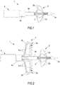
- the catheter 1 comprises a positioning head 2 and an ablation head 3, which will be described in further detail hereunder.
- the catheter 1 also comprises a handpiece in a proximal position, i.e. the control portion that is located outside and can be used for the operator for controlling the action of the catheter itself.
- the control handpiece is positioned at a proximal end of the telescopic body 4 and is operatively connected to the guiding element 5, the ablation head 3, the positioning head 2,2",2'",2°,2*,2 ⁇ and the telescopic tubular body 4; said "operative connection" can be actuated in numerous ways, all known to skilled persons in the field, for example by means of control levers directly or indirectly connected to the above-mentioned parts; consequently no further mention will be made in this respect.
- the form of the handpiece is of no particular interest for the present invention, as it is produced analogously to those known in the art; consequently no further detail is provided herein with respect to the handpiece.
- the catheter 1 comprises a telescopic tubular body 4 in turn comprising: an outer tubular body 4a, an inner tubular body 4b, concentric with respect to each other.
- a sheath 4c also eccentric with respect to the tubular bodies 4a, 4b, is also envisaged for covering the outer tubular body.
- the tubular bodies 4a and 4b are preferably cylindrical, even if, in general, they can be oval or polygonal (with rounded corners).
- the catheter 1 also comprises a rod-like guiding element 5 partly housed in the inner tubular body 4b with a free end 5a which protrudes from the inner tubular body 4b.
- the rod-like guiding element 5 is used by the surgeon for guiding the movement of the catheter 1 when inserting it into the patient's veins; this guiding element is per se of the known type and no further mention will be made thereof.
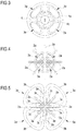
- the positioning head 2 is situated in the proximity of the free end 5a of the rod-like guide 5, whereas the ablation head 3 is situated in the proximity of the positioning head 2, but in a remote position with respect to the free end 5a; in other words, the ablation head 3, when in use, is positioned between the outer tubular body 4a and the positioning head 2 (see figures 2 or 11, 12 , for example).
- the ablation head 3 comprises a plurality of ablation elements or petals 3a.
- a specific feature of the ablation elements 3a is that they can be moved, or rather extracted, from a rest position in which they are housed in the outer tubular body 4a (as in figures 1 , 3 and 4 ) to an operating position in which they protrude from the outer tubular body 4a extending and broadening out both radially and axially towards the positioning head (as in figures 2 , 5 , 11-14 ).
- the movement between the two positions, rest and operating, is effected thanks to a mechanical control positioned in the handpiece of the device and which allows the controlled and adjustable extraction of the ablation petals 3a.
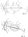
- the housing chamber 6 in which the petals 3a are positioned in a rest condition and from which they are extracted to be brought into an operating condition.
- a single housing chamber is envisaged for each petal 3a, whereas in other embodiments, such as that illustrated, there is only one chamber 6, which in a sectional and front view, is substantially in the form of a circular crown, as it is formed between the outer 4a and inner 4b tubular bodies.
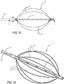
- At least one, preferably all, of the ablation elements 3a comprise a continuous (clearly visible in figure 5 ) - or distributed - ablation electrode 3b which extends without interruption over a circumferential portion, preferably peripheral, of each petal 3a, substantially along an arc of circumference having a longitudinal axis of the rod-like guiding element 5, as center.
- the electrode 3b occupies the whole of the external body of the petal 3a, as far as the folded portions with a larger curvature radius which connect it with two side portions 3c of the petal 3a, each connected to an end of the ablation electrode (3b).
- the side portions 3c and the ablation electrode 3b are integral with each other, produced with the same folded metallic conductor, to which further reference will be made hereunder.
- the petal is composed of a single, folded, solid electric conductor (wire or lamina), of which the circumferential part 3b forms the actual electrode and the side parts 3c form side portions of the petal which preferably do not contribute to the ablation process, even if traversed by an electric current.
- This effect is obtained, for example, by coating the side portions 3c with a layer of electrically insulating material, preferably a paint (not illustrated in the figures).
- Each ablation petal 3a is separate and distinct from another ablation petal of the ablation head and all the ablation petals 3a of the head are connected separately to a separate electric energy generator to cause a radiofrequency ablation under a powered condition of the ablation electrode 3b.
- the electrically conductive material forming the ablation petal 3a is preferably composed of a shape-memory metallic conductor, even more preferably a Nitinol wire, a material which is known per sé for biomedical use; it should be noted that, in general, other metals/metal alloys suitable for the purpose, can also be selected.
- the petals are of Nitinol, each produced with a single wire having a circular section with a diameter D and with the following ratio between the diameter D and the length L of the active part (circumferential part of the petal, or electrode) D/L ranging from 0.015 to 0.025, preferably equal to about 0. 02.
- the ablation electrodes 3b substantially develop along the same circumference, having the axis of the guiding element 5 as centre; only small arcs of this ideal circumference can remain unjoined (and therefore inactive in the ablation treatment); in this way, during a treatment, an important portion of a blood vessel can be ablated, leaving only small areas of tissue that do not receive direct treatment.
- These small non-treated areas can be subsequently ablated by the surgeon, if necessary, for example by rotating the whole catheter 1 on itself or, more advantageously, only the petals 3a, keeping the positioning head 2 fixed.
- the small angular extension of the arcs in which the ablation electrode 3b is not active ensures that the surface treated by each activation of the ablation petals 3a, is high, much higher than the known radiofrequency catheters with an ablation tip described above.
- the side portions 3c do not develop exactly according to a perpendicular axis to that of the guiding element 5 (more specifically, they do not lie on the plane on which the axis of the guiding element 5 is normal): the side portions 3c are in fact slightly tilted (in a side view) towards the free end 5a of the guiding element 5, specifically forming a petal.
- the side portions 3c therefore preferably develop, at least partly, along the generatrices of a cone (or truncated cone, depending on the cases) having as axis the longitudinal axis of the guiding element 5.
- one of the side portions 3c is preferably fixed to the outer tubular body, whereas the other side portion extends (or is connected) as far as the handpiece, where it is connected to the mechanical activation elements or to the specific generator for this.
- Each petal in addition to being individually activated, can also be individually extracted from the tubular body 4a in which it is housed in a non-operating condition.
- each petal is both mechanically and electrically connected to a specific conductor 39.
- the conductor 39 is integral with the petal 3a, as it is produced with the same Nitinol wire, with the same diameter.
- each petal extends as far as the handpiece, the other portion being fixed in correspondence with the terminal end of the body 4a, for example a terminal bush; the bush 37 therefore preferably slidingly houses a side portion of each petal 3c, whereas the other terminal portion of the same petal is fixed to the bush 37 itself.
- the conductors 39 of each petal substantially extend as far as the handpiece housed inside the body 4a, in the space between this and the body 4b.
- the conductors 39 are spirally wound in said space between the bodies 4a and 4b.
- Each conductor 39 is electrically isolated from the other so that the powering of one of these does not cause the powering of those nearby.
- each segment 3b and/or each element 3a is connected to a power source separately from the others and can be activated individually; for this purpose, the ablation apparatus of the invention comprises a number of radiofrequency electric energy generators equal to that of the petals, which are connected separated and individually to each generator by means of the conductors 39.
- Each electrode 3b and/or each petal 3a is therefore connected individually to and can be powered individually by an electric energy source (preferably a radiofrequency generator).
- an electric energy source preferably a radiofrequency generator
- the surgeon can therefore choose which electrodes 3b and/or petals 3a to activate depending on the treatment conditions, and can also repeat it only in correspondence with areas that have not been sufficiently treated and/or avoid activating areas of risk for the patient.
- each petal 3a can be advantageously moved individually (with respect to the others) between the rest condition and the, extracted, operating condition.
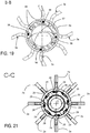
- the ablation petals 3a are optionally rotatingly associated with the telescopic body 4 so that they can be rotated without causing the body 4 and/or the positioning head 2 to also rotate; this is obtained, for example in the case of the embodiment of figures 11-21 , making the terminal bush 37 (provided with seats in which the conductors 39 pass axially before being connected to the portions 3c) rotate freely with respect to the body 4a.
- the petals 3a are preferably controlled by the handpiece of the device, by means of a mechanical, or electric or pneumatic control.
- At least one - preferably a plurality - of additional conductors 38 is envisaged, partly housed in the telescopic tubular body 4, shown in the preferred embodiment of figures 11-21 .
- the additional conductors 38 are also housed in the body 4a, in the space between this and the body 4b, adjacent to the conductors 39, in particular spirally arranged and interspersed with the latter.
- Said additional conductors 38 are not in electric contact with the petals 3a and serve to reduce the eddy currents and allow a better control of the energy supplied to each petal during the operating phase of the catheter.
- Eddy currents are generated on the electrodes that are not fed due to those that are being fed at the same time by the respective generator and also cause the powering of the electrodes which, on the other hand, should not be fed.
- the additional conductors 39 are preferably completely contained in the telescopic tubular body 4 and exit from this only on the side of the handpiece.
- Each additional conductor is preferably "U"-folded inside the body, with the two free ends exiting from the proximal side and the folded part which extends into the tubular body as far as its end; alternatively and preferably, all or only part of the additional conductors can be electrically connected to each other.
- the additional conductors 39 are preferably copper wires.
- each supply conductor 39 of a petal is adjacent, on the two opposite sides, to two branches of the same - or different - additional conductors 38.
- the ablation head 3 comprises at least one contact sensor, capable of measuring the contact with the surface to be treated, effecting the treatment with greater precision.
- said contact sensor is a capacitive sensor, which indirectly measures the percentage of the electrode 3b which is in contact with the tissue.
- the same electrode 3b acts as electrode of the capacitive sensor: by passing a control current, it is in fact possible to reveal whether the same is or is not in contact with the tissue.
- RF RadioFrequency
- this comprises a plurality of extractable positioning arms 2a.
- Said arms 2a pass from a rest position, in which they are housed in the inner tubular body 4b, to an extracted, operating, position, in which they protrude radially from this.
- the extractable positioning arms 2a remain withdrawn during the insertion phase of the catheter into the vein, until this has reached the area to be treated, so as not to represent an obstacle during this phase, and they are extracted to maintain the position reached, buffered against the walls of the vein/artery to be treated.
- the extractable arms 2a are preferably housed between the inner tubular body 4b and the rod-like guiding element 5.
- the extractable arms 2a form a kind of positioning cage, destined for abutting inside the vein, so as to keep the ablation head correctly in position in correspondence with the ostium of the vein itself.
- the extractable positioning arms 2a are controlled, in the extraction/re-insertion movement (from the rest position to the operating position and vice versa) by means of a mechanical system situated in the handpiece of the device and which allows the controlled and adjustable exiting of the extractable elements 2a.
- the positioning head is an inflatable body (not shown) which is expanded from the rest position to the operating position, like a balloon.
- the inflatable body is preferably housed, under rest conditions, inside the tubular body 4.
- the inflatable body moreover, has the advantage of being able to be filled with radio-opaque fluid for a better and more precise visualization.
- the positioning head 2 comprises at least one sensor capable of revealing electric potentials in the tissue, consequently allowing the completeness of the ablation effected, to be revealed.
- This sensor can be produced in various ways, according to the case.
- the positioning head 2 comprises metal arms 2a
- these in practice, form the electrode for the detection, thanks to which the electric potentials of the vein are revealed and the isolation of the vein is verified during and at the end of the treatment.
- the guiding rod-like element 5 slides in the inner tubular body 4b; the positioning head 2, 2", 2''', 2°, 2*, 2 ⁇ , under rest conditions, has such dimensions that it can be inserted in the inner tubular body 4b.
- the catheter 1 can then be inserted into the vein so as to occupy a minimum space and there are no protrusions which could obstruct its passage in the patient's body, subsequently, when the catheter 1 is in the area to be treated, the rod-like element 5 is extracted from the inner tubular body 4b and, when the catheter has reached a correct position, in which it must be fixed, the positioning head 2, 2", 2"', 2°, 2*, 2 ⁇ , is enlarged or, rather, its arms 2a, 2a",2a"',2a°,2a*,2a ⁇ are enlarged, which pass from a rest position to an enlarged position and can be abutted against the surrounding tissues, so as to keep the catheter 1 in position.
- the catheter 1 is shown with the ablation head in a rest condition and, for the sake of clarity, only the positioning head is illustrated.
- Fig. 6 shows a positioning head 2'' in an enlarged condition, which comprises only one arm 2a", in the form of a spiral which develops around the rod-like element 5.
- the arm 2a When in an extracted condition, the arm 2a" rests with its coils on the tissue, helping to keep the catheter 1 in position.
- Figures 7, 8 , 9 and 10 show, in an enlarged condition, the positioning heads 2"', 2°, 2* and 2 ⁇ each comprising arms 2a"', 2a°, 2a* and 2a ⁇ which extend according to different geometries around the rod-like element 5:
- each extractable arm 2a, 2a",2a"',2a°,2a* and 2a ⁇ is arched (even if it does not develop according an actual arc of circumference except for the arms 2a°) and extends substantially between said inner tubular body (4b) and said free end (5a) of said rod-like element (5).
- each arm 2a of the head 2 also extends into the body 4b as far as the handpiece by means of elongated spiral-shaped portions 29.
- Each elongated portion is preferably integral with the respective arm 2a and is produced in the same material, preferably conductive such as Nitinol or similar.
- each elongated portion 29 is electrically isolated from the others, so that possible electric signals can be revealed (or transmitted) by the arms 2a independently of each other.
- additional second conductors 28 are envisaged for the positioning head 2, with advantages similar to those described above for the first additional conductors 38 (relating to the eddy currents).
- Additional conductors 28 develop on a helix having the same pitch and the same diameter with respect to the elongated portions 29, and are interspersed with the latter, so that each elongated portion 29 of an arm 2a is adjacent, at the two opposite sides, to two branches of the same - or different - additional conductor (s) 28.
- the additional conductors 28 are preferably made of copper, preferably shaped like U-folded wires inside the body 4b (or, alternatively, preferably all or part of them are electrically connected to each other), between this and the guidewire, analogously to the additional conductors 38 described above.
- the above-mentioned additional dissipative conductors 28, 38 are preferably electrically connected to ground.
Landscapes
- Health & Medical Sciences (AREA)
- Life Sciences & Earth Sciences (AREA)
- Surgery (AREA)
- Engineering & Computer Science (AREA)
- Plasma & Fusion (AREA)
- General Health & Medical Sciences (AREA)
- Otolaryngology (AREA)
- Physics & Mathematics (AREA)
- Veterinary Medicine (AREA)
- Biomedical Technology (AREA)
- Heart & Thoracic Surgery (AREA)
- Medical Informatics (AREA)
- Molecular Biology (AREA)
- Animal Behavior & Ethology (AREA)
- Nuclear Medicine, Radiotherapy & Molecular Imaging (AREA)
- Public Health (AREA)
- Cardiology (AREA)
- Surgical Instruments (AREA)
Claims (14)
- Cathéter (1) pour l'ablation de tissus comprenant :- un corps tubulaire télescopique (4) qui comprend à son tour un corps tubulaire externe (4a) et un corps tubulaire interne (4b), concentriques l'un à l'autre, et un élément de guidage en forme de tige (5) logé au moins en partie dans le corps tubulaire interne (4b) avec au moins une extrémité libre (5a) faisant saillie du corps tubulaire interne (4b) en correspondance avec une extrémité distale du corps télescopique (4) ;- une tête de positionnement (2, 2", 2"', 2°, 2*, 2^) et une tête d'ablation (3) en correspondance avec l'extrémité distale du corps télescopique (4), la tête de positionnement (2, 2", 2"', 2°, 2*, 2^) est située à proximité de l'extrémité libre (5a) de l'élément de guidage en forme de tige, et la tête d'ablation (3) est située à proximité de la tête de positionnement (2, 2", 2"', 2°, 2*, 2^), dans une position distante par rapport à l'extrémité libre (5a) ;- une pièce à main de commande à une extrémité proximale du corps télescopique (4), couplée à l'élément de guidage (5), la tête d'ablation (3), la tête de positionnement (2, 2", 2'", 2°, 2*, 2^) et le corps tubulaire télescopique (4) ;dans lequel la tête d'ablation (3) comprend au moins deux éléments ou pétales d'ablation (3a) pouvant être déplacés d'une position de repos, dans laquelle ils sont logés dans le corps tubulaire externe (4a), et d'une position de fonctionnement, dans laquelle ils font saillie depuis le corps tubulaire externe (4a) comme un pétale ;
chacun des éléments ou des pétales d'ablation (3a) comprend :- une électrode d'ablation continue (3b) qui s'étend sans interruption sur une partie périphérique circonférentielle de chaque pétale (3a), sensiblement le long d'un arc de circonférence ayant au centre un axe longitudinal de l'élément de guidage en forme de tige (5) ;- deux parties latérales (3c) du pétale (3a), chacune connectée à une extrémité de l'électrode d'ablation (3b), en correspondance avec une section incurvée,chaque pétale d'ablation (3a) étant séparé et distinct d'un autre pétale d'ablation (3a) de la tête d'ablation,
tous les pétales d'ablation (3a) de la tête d'ablation étant connectés séparément à un générateur d'énergie électrique distinct pour provoquer une ablation par radiofréquence dans un état d'électrode d'ablation alimentée (3b),
caractérisé en ce que
les parties latérales (3c) et l'électrode d'ablation (3b) sont mutuellement solidaires, formées au moyen du même conducteur métallique plié,
et dans lequel
chaque pétale d'ablation (3a) est réalisé avec un seul fil de Nitinol présentant une section circulaire de diamètre D et, sachant que L est la longueur linéaire de l'électrode d'ablation, il y a le rapport D/L suivant qui est entre 0,015 et 0,025. - Cathéter (1) selon la revendication précédente, dans lequel ledit rapport D/L est égal à environ 0,02.
- Cathéter (1) selon une ou plusieurs des revendications précédentes, dans lequel les deux parties latérales (3c) de chaque pétale (3a) sont revêtues d'un matériau d'isolation électrique, de préférence une peinture isolante.
- Cathéter (1) selon une ou plusieurs des revendications précédentes, comprenant, pour chaque pétale, au moins un conducteur (39) qui s'étend jusqu'à la pièce à main pour alimenter individuellement chaque pétale, ledit conducteur (39) s'étend à l'intérieur du corps externe (4a), dans l'espace entre celui-ci et le corps interne (4b), de préférence disposé en spirale.
- Cathéter (1) selon une ou plusieurs des revendications précédentes, comprenant, pour chaque pétale, au moins un premier conducteur supplémentaire (38) logé au moins en partie dans le corps tubulaire télescopique (4), et destiné à s'étendre de préférence à partir de la pièce à main jusqu'au bout du corps externe (4b).
- Cathéter (1) selon la revendication précédente, dans lequel chaque premier conducteur supplémentaire (38) se développe en spirale à l'intérieur du corps externe (4a), et dans lequel lesdits conducteurs (39) alternent avec au moins un conducteur supplémentaire (38), à l'intérieur dudit corps externe (4a).
- Cathéter (1) selon une ou plusieurs des revendications précédentes, dans lequel chaque pétale (3a) peut être déplacé individuellement par rapport aux autres entre la position de repos et la position de fonctionnement (extrait).
- Cathéter (1) selon une ou plusieurs des revendications précédentes, dans lequel les pétales d'ablation (3a) sont associés en rotation au corps télescopique (4) de sorte qu'ils soient susceptibles d'être entraînés en rotation sans provoquer même la rotation du corps (4) et/ou de la tête de positionnement (2, 2", 2'", 2°, 2*, 2^).
- Cathéter (1) selon une ou plusieurs des revendications précédentes, dans lequel la tête de positionnement (2, 2", 2"', 2°, 2*, 2^) comprend au moins un bras de positionnement extractible (2a, 2a", 2a"', 2a°, 2a*, 2a^), ledit bras de positionnement extractible (2a, 2a", 2a"', 2a°, 2a*, 2a^) étant susceptible d'être déplacé entre une position de repos, dans laquelle il est logé dans le corps tubulaire interne (4b), et une position de fonctionnement, extrait, dans laquelle il fait saillie de façon radiale par rapport au corps tubulaire interne (4b).
- Cathéter (1) selon une ou plusieurs des revendications précédentes, dans lequel la tête de positionnement (2, 2", 2"', 2°, 2*, 2^) comprend au moins un capteur capable de révéler des potentiels électriques dans le tissu et permettant de révéler que l'ablation effectuée est complète.
- Cathéter (1) selon la revendication précédente, dans lequel lesdits bras (2a, 2a", 2a'", 2a°, 2a*, 2a^) sont métalliques et forment l'électrode de détection.
- Cathéter (1) selon la revendication précédente, dans lequel chaque bras est connecté à au moins une partie allongée (29) qui s'étend jusqu'à la pièce à main, logée dans le corps interne (4b) et de préférence en forme de spirale.
- Cathéter (1) selon la revendication 12, dans lequel des seconds conducteurs supplémentaires (28) sont envisagés pour la tête de positionnement (2), lesquels se développent de préférence en spirale et sont entrecoupés des dites parties allongées (29).
- Appareil d'ablation des tissus comprenant un cathéter selon une ou plusieurs des revendications 1 à 13 et au moins un générateur d'énergie électrique pour chaque pétale dudit cathéter, connecté électriquement à ce pétale.
Priority Applications (1)
| Application Number | Priority Date | Filing Date | Title |
|---|---|---|---|
| PL15718091T PL3125802T3 (pl) | 2014-03-20 | 2015-03-18 | Cewnik ablacyjny i urządzenie ablacyjne |
Applications Claiming Priority (2)
| Application Number | Priority Date | Filing Date | Title |
|---|---|---|---|
| ITMI20140467 | 2014-03-20 | ||
| PCT/IB2015/051998 WO2015140741A1 (fr) | 2014-03-20 | 2015-03-18 | Cathéter d'ablation et appareil d'ablation |
Publications (2)
| Publication Number | Publication Date |
|---|---|
| EP3125802A1 EP3125802A1 (fr) | 2017-02-08 |
| EP3125802B1 true EP3125802B1 (fr) | 2019-03-13 |
Family
ID=50693827
Family Applications (1)
| Application Number | Title | Priority Date | Filing Date |
|---|---|---|---|
| EP15718091.0A Active EP3125802B1 (fr) | 2014-03-20 | 2015-03-18 | Cathéter d'ablation et appareil d'ablation |
Country Status (18)
| Country | Link |
|---|---|
| US (2) | US10980597B2 (fr) |
| EP (1) | EP3125802B1 (fr) |
| JP (1) | JP6507226B2 (fr) |
| KR (1) | KR102357921B1 (fr) |
| CN (1) | CN106102628B (fr) |
| AU (1) | AU2015232999A1 (fr) |
| BR (1) | BR112016021515B1 (fr) |
| CA (2) | CA3200528A1 (fr) |
| ES (1) | ES2730967T3 (fr) |
| GE (1) | GEP20197025B (fr) |
| IL (1) | IL247777B (fr) |
| MX (1) | MX2016011953A (fr) |
| PL (1) | PL3125802T3 (fr) |
| RU (1) | RU2678229C1 (fr) |
| SG (1) | SG11201706466SA (fr) |
| TR (1) | TR201908664T4 (fr) |
| WO (1) | WO2015140741A1 (fr) |
| ZA (1) | ZA201607094B (fr) |
Families Citing this family (44)
| Publication number | Priority date | Publication date | Assignee | Title |
|---|---|---|---|---|
| WO2014025394A1 (fr) | 2012-08-09 | 2014-02-13 | University Of Iowa Research Foundation | Cathéters, systèmes de cathéter et procédés de perforation à travers une structure de tissu |
| US9848947B2 (en) * | 2013-12-11 | 2017-12-26 | Boston Scientific Scimed, Inc. | Devices and methods for prostate tissue ablation and/or resection |
| WO2015103574A1 (fr) | 2014-01-06 | 2015-07-09 | Iowa Approach Inc. | Appareil et procédés pour ablation de dénervation rénale |
| EP3495018B1 (fr) | 2014-05-07 | 2023-09-06 | Farapulse, Inc. | Appareil d'ablation de tissus sélectifs |
| WO2015192027A1 (fr) | 2014-06-12 | 2015-12-17 | Iowa Approach Inc. | Procédé et appareil d'ablation transurétrale de tissu rapide et sélective |
| EP3154464A4 (fr) | 2014-06-12 | 2018-01-24 | Iowa Approach Inc. | Procédé et appareil d'ablation de tissu rapide et sélective à l'aide de refroidissement |
| WO2016060983A1 (fr) | 2014-10-14 | 2016-04-21 | Iowa Approach Inc. | Procédé et appareil pour l'ablation rapide et sûre d'une veine cardiopulmonaire |
| CA3234408A1 (fr) | 2015-05-12 | 2016-11-17 | National University Of Ireland Galway | Dispositifs pour la neuromodulation nasale therapeutique et procedes et systemes associes |
| US10660702B2 (en) | 2016-01-05 | 2020-05-26 | Farapulse, Inc. | Systems, devices, and methods for focal ablation |
| US20170189097A1 (en) | 2016-01-05 | 2017-07-06 | Iowa Approach Inc. | Systems, apparatuses and methods for delivery of ablative energy to tissue |
| JP6847960B2 (ja) * | 2016-01-05 | 2021-03-24 | ファラパルス,インコーポレイテッド | パルス電界の焼灼エネルギーを心内膜組織に送出するためのシステム、装置、及び方法 |
| US10172673B2 (en) | 2016-01-05 | 2019-01-08 | Farapulse, Inc. | Systems devices, and methods for delivery of pulsed electric field ablative energy to endocardial tissue |
| US10130423B1 (en) | 2017-07-06 | 2018-11-20 | Farapulse, Inc. | Systems, devices, and methods for focal ablation |
| US9987081B1 (en) | 2017-04-27 | 2018-06-05 | Iowa Approach, Inc. | Systems, devices, and methods for signal generation |
| US10617867B2 (en) | 2017-04-28 | 2020-04-14 | Farapulse, Inc. | Systems, devices, and methods for delivery of pulsed electric field ablative energy to esophageal tissue |
| JP2020533050A (ja) | 2017-09-12 | 2020-11-19 | ファラパルス,インコーポレイテッド | 心室フォーカルアブレーションのためのシステム、装置、及び方法 |
| KR102067989B1 (ko) * | 2018-03-26 | 2020-01-20 | (주) 타우피엔유메디칼 | 심근 전기 신호 감지 캡쳐카테터 |
| US20190336198A1 (en) | 2018-05-03 | 2019-11-07 | Farapulse, Inc. | Systems, devices, and methods for ablation using surgical clamps |
| WO2019217317A1 (fr) | 2018-05-07 | 2019-11-14 | Farapulse, Inc. | Systèmes, appareils et procédés pour filtrer un bruit haute tension induit par une ablation par champ électrique pulsé |
| CN112087978B (zh) | 2018-05-07 | 2023-01-17 | 波士顿科学医学有限公司 | 心外膜消融导管 |
| CN115836908A (zh) | 2018-05-07 | 2023-03-24 | 波士顿科学医学有限公司 | 用于将消融能量递送到组织的系统、设备和方法 |
| EP3852661A1 (fr) | 2018-09-20 | 2021-07-28 | Farapulse, Inc. | Systèmes, appareils et méthodes d'application d'une énergie d'ablation à champ électrique pulsé à un tissu endocardiaque |
| US11684414B2 (en) * | 2018-12-11 | 2023-06-27 | Neurent Medical Limited | Systems and methods for therapeutic nasal neuromodulation |
| CN111374658A (zh) * | 2018-12-29 | 2020-07-07 | 上海微创电生理医疗科技股份有限公司 | 电生理导管 |
| WO2021007416A1 (fr) * | 2019-07-09 | 2021-01-14 | Ecom Medical, Inc. | Dispositifs médicaux ayant des jonctions conductrices |
| US11540878B2 (en) * | 2019-07-17 | 2023-01-03 | Biosense Webster (Israel) Ltd. | Blooming leaflet catheter with high density electrode array |
| US10625080B1 (en) | 2019-09-17 | 2020-04-21 | Farapulse, Inc. | Systems, apparatuses, and methods for detecting ectopic electrocardiogram signals during pulsed electric field ablation |
| US11065047B2 (en) | 2019-11-20 | 2021-07-20 | Farapulse, Inc. | Systems, apparatuses, and methods for protecting electronic components from high power noise induced by high voltage pulses |
| US11497541B2 (en) | 2019-11-20 | 2022-11-15 | Boston Scientific Scimed, Inc. | Systems, apparatuses, and methods for protecting electronic components from high power noise induced by high voltage pulses |
| US10842572B1 (en) | 2019-11-25 | 2020-11-24 | Farapulse, Inc. | Methods, systems, and apparatuses for tracking ablation devices and generating lesion lines |
| CN112741682B (zh) * | 2020-12-31 | 2022-04-01 | 杭州堃博生物科技有限公司 | 射频消融导管及射频消融系统 |
| RU2738134C1 (ru) * | 2020-02-11 | 2020-12-08 | Федеральное государственное бюджетное научное учреждение "Российский научный центр хирургии имени академика Б.В. Петровского" | Способ фиксации зонда для хирургической абляции |
| WO2021205230A1 (fr) * | 2020-04-09 | 2021-10-14 | Neurent Medical Limited | Systèmes et procédés de traitement nasal thérapeutique |
| US11883091B2 (en) | 2020-04-09 | 2024-01-30 | Neurent Medical Limited | Systems and methods for improving sleep with therapeutic nasal treatment |
| EP4173581A4 (fr) * | 2020-06-28 | 2024-07-24 | Hangzhou Dinova Ep Tech Co Ltd | Dispositif d'ablation et système d'ablation |
| US20220061912A1 (en) * | 2020-08-25 | 2022-03-03 | Biosense Webster (Israel) Ltd. | Blending ire and rf ablation using a sine wave generator |
| US20220104869A1 (en) * | 2020-10-06 | 2022-04-07 | Neurent Medical Limited | Systems and methods for therapeutic nasal treatment |
| EP4304508A1 (fr) * | 2021-03-10 | 2024-01-17 | Galvanize Therapeutics, Inc. | Dispositifs servant à l'administration de champs électriques pulsés dans le traitement de tissu cardiaque |
| US20230372009A1 (en) * | 2021-04-26 | 2023-11-23 | Pulse Biosciences, Inc. | Multi-strut ablation and sensing catheter devices and methods |
| CN113729923B (zh) * | 2021-09-30 | 2022-07-12 | 上海睿刀医疗科技有限公司 | 面消融电极导管及消融设备 |
| CN114469327B (zh) * | 2021-12-24 | 2024-02-27 | 上海科罡医疗技术有限公司 | 一种消融导管及其消融治疗方法 |
| WO2023158283A1 (fr) * | 2022-02-21 | 2023-08-24 | 가톨릭대학교 산학협력단 | Outil d'ablation chirurgical utilisant une stimulation électrique |
| CN114848135B (zh) * | 2022-07-05 | 2022-09-09 | 中国医学科学院阜外医院 | 一种新型外科手术的射频消融钳 |
| CN117547347B (zh) * | 2024-01-11 | 2024-07-05 | 乐普(北京)医疗器械股份有限公司 | 一种射频消融装置 |
Family Cites Families (25)
| Publication number | Priority date | Publication date | Assignee | Title |
|---|---|---|---|---|
| US5772590A (en) * | 1992-06-30 | 1998-06-30 | Cordis Webster, Inc. | Cardiovascular catheter with laterally stable basket-shaped electrode array with puller wire |
| US5309910A (en) * | 1992-09-25 | 1994-05-10 | Ep Technologies, Inc. | Cardiac mapping and ablation systems |
| US5471982A (en) | 1992-09-29 | 1995-12-05 | Ep Technologies, Inc. | Cardiac mapping and ablation systems |
| US6233491B1 (en) * | 1993-03-16 | 2001-05-15 | Ep Technologies, Inc. | Cardiac mapping and ablation systems |
| US6652515B1 (en) * | 1997-07-08 | 2003-11-25 | Atrionix, Inc. | Tissue ablation device assembly and method for electrically isolating a pulmonary vein ostium from an atrial wall |
| US6179832B1 (en) * | 1997-09-11 | 2001-01-30 | Vnus Medical Technologies, Inc. | Expandable catheter having two sets of electrodes |
| US6315778B1 (en) * | 1999-09-10 | 2001-11-13 | C. R. Bard, Inc. | Apparatus for creating a continuous annular lesion |
| US6529756B1 (en) * | 1999-11-22 | 2003-03-04 | Scimed Life Systems, Inc. | Apparatus for mapping and coagulating soft tissue in or around body orifices |
| US6652517B1 (en) * | 2000-04-25 | 2003-11-25 | Uab Research Foundation | Ablation catheter, system, and method of use thereof |
| CN1165602C (zh) | 2002-09-16 | 2004-09-08 | 张普华 | 一种把水-乙醇混合物转化为可燃物的方法及其装置 |
| EP1596746B1 (fr) * | 2003-02-20 | 2016-10-19 | ReCor Medical, Inc. | Dispositifs d'ablation ultrasonique |
| CA2519636A1 (fr) | 2003-03-27 | 2004-10-14 | Cierra, Inc. | Procedes et appareil pour le traitement de foramen ovale permeable |
| WO2004105807A2 (fr) * | 2003-05-27 | 2004-12-09 | Venture Manufacturing, Llc | Dispositif d'ablation a deploiement radialement centre de ballon |
| US20060089637A1 (en) * | 2004-10-14 | 2006-04-27 | Werneth Randell L | Ablation catheter |
| EP2001383A4 (fr) * | 2006-03-17 | 2011-01-19 | Microcube Llc | Dispositifs et procédés permettant de produire des lésions continues |
| WO2008065609A1 (fr) * | 2006-11-28 | 2008-06-05 | Koninklijke Philips Electronics N.V. | Appareil, procede et programme informatique permettant d'appliquer de l'energie sur un objet |
| AU2008207657A1 (en) * | 2007-09-28 | 2009-04-23 | Cathrx Ltd | A catheter assembly |
| EP2205309A4 (fr) | 2007-10-05 | 2011-05-11 | Coaptus Medical Corp | Systèmes et procédés pour procédures cardiaques transeptales comprenant des câbles de guidage séparables, des éléments de pénétration de tissus, des éléments de scellage de tissus et des dispositifs de compression de tissus |
| US8712550B2 (en) * | 2008-12-30 | 2014-04-29 | Biosense Webster, Inc. | Catheter with multiple electrode assemblies for use at or near tubular regions of the heart |
| US8442613B2 (en) | 2009-07-29 | 2013-05-14 | Boston Scientific Scimed, Inc | Mapping probe assembly with skived tube body frame |
| ES2940658T3 (es) | 2010-05-05 | 2023-05-10 | Electrophysiology Frontiers S P A | Catéter de ablación cardíaca anclado |
| WO2012149511A2 (fr) * | 2011-04-28 | 2012-11-01 | Synecor Llc | Systèmes de neuromodulation et procédés pour traiter des syndromes d'insuffisance cardiaque aiguë |
| US8998893B2 (en) * | 2010-12-07 | 2015-04-07 | Boaz Avitall | Catheter systems for cardiac arrhythmia ablation |
| US20140358135A1 (en) * | 2013-05-29 | 2014-12-04 | Medtronic Cryocath Lp | Method and apparatus for using phonomyography to prevent nerve damage during a medical procedure |
| US9351789B2 (en) * | 2013-05-31 | 2016-05-31 | Medtronic Ablation Frontiers Llc | Adjustable catheter for ostial, septal, and roof ablation in atrial fibrillation patients |
-
2015
- 2015-03-18 WO PCT/IB2015/051998 patent/WO2015140741A1/fr active Application Filing
- 2015-03-18 CA CA3200528A patent/CA3200528A1/fr active Pending
- 2015-03-18 PL PL15718091T patent/PL3125802T3/pl unknown
- 2015-03-18 SG SG11201706466SA patent/SG11201706466SA/en unknown
- 2015-03-18 KR KR1020167029129A patent/KR102357921B1/ko active IP Right Grant
- 2015-03-18 GE GEAP2015014560 patent/GEP20197025B/en unknown
- 2015-03-18 TR TR2019/08664T patent/TR201908664T4/tr unknown
- 2015-03-18 JP JP2017500464A patent/JP6507226B2/ja active Active
- 2015-03-18 RU RU2017132699A patent/RU2678229C1/ru active
- 2015-03-18 EP EP15718091.0A patent/EP3125802B1/fr active Active
- 2015-03-18 AU AU2015232999A patent/AU2015232999A1/en not_active Abandoned
- 2015-03-18 BR BR112016021515-0A patent/BR112016021515B1/pt active IP Right Grant
- 2015-03-18 ES ES15718091T patent/ES2730967T3/es active Active
- 2015-03-18 CA CA2976749A patent/CA2976749C/fr active Active
- 2015-03-18 CN CN201580014964.4A patent/CN106102628B/zh active Active
- 2015-03-18 US US15/127,464 patent/US10980597B2/en active Active
- 2015-03-18 MX MX2016011953A patent/MX2016011953A/es unknown
-
2016
- 2016-09-12 IL IL247777A patent/IL247777B/en unknown
- 2016-10-14 ZA ZA2016/07094A patent/ZA201607094B/en unknown
-
2021
- 2021-03-29 US US17/216,236 patent/US20210212760A1/en active Pending
Non-Patent Citations (1)
| Title |
|---|
| None * |
Also Published As
| Publication number | Publication date |
|---|---|
| ES2730967T3 (es) | 2019-11-13 |
| US20210212760A1 (en) | 2021-07-15 |
| CN106102628B (zh) | 2020-10-27 |
| SG11201706466SA (en) | 2017-09-28 |
| EP3125802A1 (fr) | 2017-02-08 |
| TR201908664T4 (tr) | 2019-07-22 |
| WO2015140741A1 (fr) | 2015-09-24 |
| CA2976749A1 (fr) | 2015-09-24 |
| JP6507226B2 (ja) | 2019-04-24 |
| PL3125802T3 (pl) | 2020-05-18 |
| CA3200528A1 (fr) | 2015-09-24 |
| IL247777B (en) | 2021-08-31 |
| IL247777A0 (en) | 2016-11-30 |
| JP2017509458A (ja) | 2017-04-06 |
| BR112016021515A2 (fr) | 2017-08-15 |
| ZA201607094B (en) | 2017-08-30 |
| CN106102628A (zh) | 2016-11-09 |
| RU2678229C1 (ru) | 2019-01-24 |
| MX2016011953A (es) | 2017-05-04 |
| US10980597B2 (en) | 2021-04-20 |
| CA2976749C (fr) | 2023-08-01 |
| AU2015232999A1 (en) | 2016-11-03 |
| BR112016021515B1 (pt) | 2022-07-26 |
| KR102357921B1 (ko) | 2022-02-03 |
| GEP20197025B (en) | 2019-10-10 |
| US20170151014A1 (en) | 2017-06-01 |
| KR20160145034A (ko) | 2016-12-19 |
Similar Documents
| Publication | Publication Date | Title |
|---|---|---|
| US20210212760A1 (en) | Ablation catheter and ablation apparatus | |
| US12042218B2 (en) | Pulmonary vein isolation balloon catheter | |
| US11213678B2 (en) | Method of manufacturing a medical device for neuromodulation | |
| EP3643259B1 (fr) | Cathéter de cavitation | |
| US6972016B2 (en) | Helically shaped electrophysiology catheter | |
| EP2890321B1 (fr) | Système d'ablation rénale par rf pourvu d'une électrode virtuelle mobile | |
| US9173696B2 (en) | Self-positioning electrode system and method for renal nerve modulation | |
| CN112535529B (zh) | 适于与导丝一起使用以进入血管的导管 | |
| JP2017531544A (ja) | 方向変更送達カテーテル及びその使用方法 | |
| US20160113711A1 (en) | Ablation catheter and method of forming a circular lesion | |
| EP4134031B1 (fr) | Systèmes d'électroporation à l'aide de formes d'ondes asymétriques et de formes d'ondes à durée de rafale réduite | |
| WO2024039373A1 (fr) | Cathéter à ballonnet ayant une capacité d'incision améliorée | |
| WO2016186950A1 (fr) | Cathéter d'ablation expansible |
Legal Events
| Date | Code | Title | Description |
|---|---|---|---|
| STAA | Information on the status of an ep patent application or granted ep patent |
Free format text: STATUS: THE INTERNATIONAL PUBLICATION HAS BEEN MADE |
|
| PUAI | Public reference made under article 153(3) epc to a published international application that has entered the european phase |
Free format text: ORIGINAL CODE: 0009012 |
|
| STAA | Information on the status of an ep patent application or granted ep patent |
Free format text: STATUS: REQUEST FOR EXAMINATION WAS MADE |
|
| 17P | Request for examination filed |
Effective date: 20161020 |
|
| AK | Designated contracting states |
Kind code of ref document: A1 Designated state(s): AL AT BE BG CH CY CZ DE DK EE ES FI FR GB GR HR HU IE IS IT LI LT LU LV MC MK MT NL NO PL PT RO RS SE SI SK SM TR |
|
| AX | Request for extension of the european patent |
Extension state: BA ME |
|
| RIC1 | Information provided on ipc code assigned before grant |
Ipc: A61B 18/14 20060101AFI20180823BHEP Ipc: A61B 18/00 20060101ALN20180823BHEP Ipc: A61B 18/12 20060101ALN20180823BHEP |
|
| GRAP | Despatch of communication of intention to grant a patent |
Free format text: ORIGINAL CODE: EPIDOSNIGR1 |
|
| STAA | Information on the status of an ep patent application or granted ep patent |
Free format text: STATUS: GRANT OF PATENT IS INTENDED |
|
| INTG | Intention to grant announced |
Effective date: 20180928 |
|
| GRAS | Grant fee paid |
Free format text: ORIGINAL CODE: EPIDOSNIGR3 |
|
| GRAA | (expected) grant |
Free format text: ORIGINAL CODE: 0009210 |
|
| STAA | Information on the status of an ep patent application or granted ep patent |
Free format text: STATUS: THE PATENT HAS BEEN GRANTED |
|
| AK | Designated contracting states |
Kind code of ref document: B1 Designated state(s): AL AT BE BG CH CY CZ DE DK EE ES FI FR GB GR HR HU IE IS IT LI LT LU LV MC MK MT NL NO PL PT RO RS SE SI SK SM TR |
|
| AX | Request for extension of the european patent |
Extension state: BA ME |
|
| REG | Reference to a national code |
Ref country code: GB Ref legal event code: FG4D |
|
| REG | Reference to a national code |
Ref country code: AT Ref legal event code: REF Ref document number: 1106624 Country of ref document: AT Kind code of ref document: T Effective date: 20190315 Ref country code: CH Ref legal event code: EP |
|
| REG | Reference to a national code |
Ref country code: IE Ref legal event code: FG4D |
|
| REG | Reference to a national code |
Ref country code: DE Ref legal event code: R096 Ref document number: 602015026314 Country of ref document: DE |
|
| REG | Reference to a national code |
Ref country code: NL Ref legal event code: FP |
|
| RAP2 | Party data changed (patent owner data changed or rights of a patent transferred) |
Owner name: ELECTROPHYSIOLOGY FRONTIERS S.P.A. |
|
| REG | Reference to a national code |
Ref country code: NL Ref legal event code: PD Owner name: ELECTROPHYSIOLOGY FRONTIERS S.P.A.; IT Free format text: DETAILS ASSIGNMENT: CHANGE OF OWNER(S), ASSIGNMENT; FORMER OWNER NAME: ATRICATH S.P.A. Effective date: 20190612 Ref country code: BE Ref legal event code: PD Owner name: ELECTROPHYSIOLOGY FRONTIERS S.P.A.; IT Free format text: DETAILS ASSIGNMENT: CHANGE OF OWNER(S), CESSION; FORMER OWNER NAME: ATRICATH S.P.A. Effective date: 20190612 |
|
| REG | Reference to a national code |
Ref country code: LT Ref legal event code: MG4D |
|
| PG25 | Lapsed in a contracting state [announced via postgrant information from national office to epo] |
Ref country code: SE Free format text: LAPSE BECAUSE OF FAILURE TO SUBMIT A TRANSLATION OF THE DESCRIPTION OR TO PAY THE FEE WITHIN THE PRESCRIBED TIME-LIMIT Effective date: 20190313 Ref country code: NO Free format text: LAPSE BECAUSE OF FAILURE TO SUBMIT A TRANSLATION OF THE DESCRIPTION OR TO PAY THE FEE WITHIN THE PRESCRIBED TIME-LIMIT Effective date: 20190613 Ref country code: FI Free format text: LAPSE BECAUSE OF FAILURE TO SUBMIT A TRANSLATION OF THE DESCRIPTION OR TO PAY THE FEE WITHIN THE PRESCRIBED TIME-LIMIT Effective date: 20190313 Ref country code: LT Free format text: LAPSE BECAUSE OF FAILURE TO SUBMIT A TRANSLATION OF THE DESCRIPTION OR TO PAY THE FEE WITHIN THE PRESCRIBED TIME-LIMIT Effective date: 20190313 |
|
| REG | Reference to a national code |
Ref country code: DE Ref legal event code: R081 Ref document number: 602015026314 Country of ref document: DE Owner name: ELECTROPHYSIOLOGY FRONTIERS S.P.A., IT Free format text: FORMER OWNER: ATRICATH S.P.A., MILAN, IT |
|
| PG25 | Lapsed in a contracting state [announced via postgrant information from national office to epo] |
Ref country code: HR Free format text: LAPSE BECAUSE OF FAILURE TO SUBMIT A TRANSLATION OF THE DESCRIPTION OR TO PAY THE FEE WITHIN THE PRESCRIBED TIME-LIMIT Effective date: 20190313 Ref country code: GR Free format text: LAPSE BECAUSE OF FAILURE TO SUBMIT A TRANSLATION OF THE DESCRIPTION OR TO PAY THE FEE WITHIN THE PRESCRIBED TIME-LIMIT Effective date: 20190614 Ref country code: RS Free format text: LAPSE BECAUSE OF FAILURE TO SUBMIT A TRANSLATION OF THE DESCRIPTION OR TO PAY THE FEE WITHIN THE PRESCRIBED TIME-LIMIT Effective date: 20190313 Ref country code: BG Free format text: LAPSE BECAUSE OF FAILURE TO SUBMIT A TRANSLATION OF THE DESCRIPTION OR TO PAY THE FEE WITHIN THE PRESCRIBED TIME-LIMIT Effective date: 20190613 Ref country code: LV Free format text: LAPSE BECAUSE OF FAILURE TO SUBMIT A TRANSLATION OF THE DESCRIPTION OR TO PAY THE FEE WITHIN THE PRESCRIBED TIME-LIMIT Effective date: 20190313 |
|
| PG25 | Lapsed in a contracting state [announced via postgrant information from national office to epo] |
Ref country code: EE Free format text: LAPSE BECAUSE OF FAILURE TO SUBMIT A TRANSLATION OF THE DESCRIPTION OR TO PAY THE FEE WITHIN THE PRESCRIBED TIME-LIMIT Effective date: 20190313 Ref country code: RO Free format text: LAPSE BECAUSE OF FAILURE TO SUBMIT A TRANSLATION OF THE DESCRIPTION OR TO PAY THE FEE WITHIN THE PRESCRIBED TIME-LIMIT Effective date: 20190313 Ref country code: SK Free format text: LAPSE BECAUSE OF FAILURE TO SUBMIT A TRANSLATION OF THE DESCRIPTION OR TO PAY THE FEE WITHIN THE PRESCRIBED TIME-LIMIT Effective date: 20190313 Ref country code: CZ Free format text: LAPSE BECAUSE OF FAILURE TO SUBMIT A TRANSLATION OF THE DESCRIPTION OR TO PAY THE FEE WITHIN THE PRESCRIBED TIME-LIMIT Effective date: 20190313 Ref country code: PT Free format text: LAPSE BECAUSE OF FAILURE TO SUBMIT A TRANSLATION OF THE DESCRIPTION OR TO PAY THE FEE WITHIN THE PRESCRIBED TIME-LIMIT Effective date: 20190713 Ref country code: AL Free format text: LAPSE BECAUSE OF FAILURE TO SUBMIT A TRANSLATION OF THE DESCRIPTION OR TO PAY THE FEE WITHIN THE PRESCRIBED TIME-LIMIT Effective date: 20190313 |
|
| REG | Reference to a national code |
Ref country code: ES Ref legal event code: FG2A Ref document number: 2730967 Country of ref document: ES Kind code of ref document: T3 Effective date: 20191113 Ref country code: GB Ref legal event code: 732E Free format text: REGISTERED BETWEEN 20191017 AND 20191023 |
|
| PG25 | Lapsed in a contracting state [announced via postgrant information from national office to epo] |
Ref country code: SM Free format text: LAPSE BECAUSE OF FAILURE TO SUBMIT A TRANSLATION OF THE DESCRIPTION OR TO PAY THE FEE WITHIN THE PRESCRIBED TIME-LIMIT Effective date: 20190313 Ref country code: LU Free format text: LAPSE BECAUSE OF NON-PAYMENT OF DUE FEES Effective date: 20190318 |
|
| REG | Reference to a national code |
Ref country code: DE Ref legal event code: R097 Ref document number: 602015026314 Country of ref document: DE |
|
| PG25 | Lapsed in a contracting state [announced via postgrant information from national office to epo] |
Ref country code: IS Free format text: LAPSE BECAUSE OF FAILURE TO SUBMIT A TRANSLATION OF THE DESCRIPTION OR TO PAY THE FEE WITHIN THE PRESCRIBED TIME-LIMIT Effective date: 20190713 |
|
| REG | Reference to a national code |
Ref country code: AT Ref legal event code: PC Ref document number: 1106624 Country of ref document: AT Kind code of ref document: T Owner name: ELECTROPHYSIOLOGY FRONTIERS S.P.A., IT Effective date: 20191203 |
|
| PLBE | No opposition filed within time limit |
Free format text: ORIGINAL CODE: 0009261 |
|
| STAA | Information on the status of an ep patent application or granted ep patent |
Free format text: STATUS: NO OPPOSITION FILED WITHIN TIME LIMIT |
|
| PG25 | Lapsed in a contracting state [announced via postgrant information from national office to epo] |
Ref country code: DK Free format text: LAPSE BECAUSE OF FAILURE TO SUBMIT A TRANSLATION OF THE DESCRIPTION OR TO PAY THE FEE WITHIN THE PRESCRIBED TIME-LIMIT Effective date: 20190313 Ref country code: MC Free format text: LAPSE BECAUSE OF FAILURE TO SUBMIT A TRANSLATION OF THE DESCRIPTION OR TO PAY THE FEE WITHIN THE PRESCRIBED TIME-LIMIT Effective date: 20190313 |
|
| 26N | No opposition filed |
Effective date: 20191216 |
|
| PG25 | Lapsed in a contracting state [announced via postgrant information from national office to epo] |
Ref country code: SI Free format text: LAPSE BECAUSE OF FAILURE TO SUBMIT A TRANSLATION OF THE DESCRIPTION OR TO PAY THE FEE WITHIN THE PRESCRIBED TIME-LIMIT Effective date: 20190313 |
|
| REG | Reference to a national code |
Ref country code: CH Ref legal event code: NV Representative=s name: VALIPAT S.A. C/O BOVARD SA NEUCHATEL, CH |
|
| VS25 | Lapsed in a validation state [announced via postgrant information from nat. office to epo] |
Ref country code: MA Free format text: LAPSE BECAUSE OF FAILURE TO SUBMIT A TRANSLATION OF THE DESCRIPTION OR TO PAY THE FEE WITHIN THE PRESCRIBED TIME-LIMIT Effective date: 20190313 |
|
| PG25 | Lapsed in a contracting state [announced via postgrant information from national office to epo] |
Ref country code: MT Free format text: LAPSE BECAUSE OF NON-PAYMENT OF DUE FEES Effective date: 20190318 |
|
| REG | Reference to a national code |
Ref country code: AT Ref legal event code: UEP Ref document number: 1106624 Country of ref document: AT Kind code of ref document: T Effective date: 20190313 |
|
| PG25 | Lapsed in a contracting state [announced via postgrant information from national office to epo] |
Ref country code: CY Free format text: LAPSE BECAUSE OF FAILURE TO SUBMIT A TRANSLATION OF THE DESCRIPTION OR TO PAY THE FEE WITHIN THE PRESCRIBED TIME-LIMIT Effective date: 20190313 |
|
| PG25 | Lapsed in a contracting state [announced via postgrant information from national office to epo] |
Ref country code: HU Free format text: LAPSE BECAUSE OF FAILURE TO SUBMIT A TRANSLATION OF THE DESCRIPTION OR TO PAY THE FEE WITHIN THE PRESCRIBED TIME-LIMIT; INVALID AB INITIO Effective date: 20150318 |
|
| PG25 | Lapsed in a contracting state [announced via postgrant information from national office to epo] |
Ref country code: MK Free format text: LAPSE BECAUSE OF FAILURE TO SUBMIT A TRANSLATION OF THE DESCRIPTION OR TO PAY THE FEE WITHIN THE PRESCRIBED TIME-LIMIT Effective date: 20190313 |
|
| P01 | Opt-out of the competence of the unified patent court (upc) registered |
Effective date: 20230530 |
|
| PGFP | Annual fee paid to national office [announced via postgrant information from national office to epo] |
Ref country code: IE Payment date: 20240321 Year of fee payment: 10 Ref country code: NL Payment date: 20240320 Year of fee payment: 10 |
|
| PGFP | Annual fee paid to national office [announced via postgrant information from national office to epo] |
Ref country code: AT Payment date: 20240321 Year of fee payment: 10 |
|
| PGFP | Annual fee paid to national office [announced via postgrant information from national office to epo] |
Ref country code: DE Payment date: 20240320 Year of fee payment: 10 Ref country code: GB Payment date: 20240320 Year of fee payment: 10 |
|
| PGFP | Annual fee paid to national office [announced via postgrant information from national office to epo] |
Ref country code: TR Payment date: 20240308 Year of fee payment: 10 Ref country code: PL Payment date: 20240308 Year of fee payment: 10 Ref country code: IT Payment date: 20240325 Year of fee payment: 10 Ref country code: FR Payment date: 20240328 Year of fee payment: 10 Ref country code: BE Payment date: 20240320 Year of fee payment: 10 |
|
| PGFP | Annual fee paid to national office [announced via postgrant information from national office to epo] |
Ref country code: CH Payment date: 20240401 Year of fee payment: 10 |
|
| PGFP | Annual fee paid to national office [announced via postgrant information from national office to epo] |
Ref country code: ES Payment date: 20240429 Year of fee payment: 10 |