EP3124902A1 - Air separation facility, operating method and control device - Google Patents
Air separation facility, operating method and control device Download PDFInfo
- Publication number
- EP3124902A1 EP3124902A1 EP16001509.5A EP16001509A EP3124902A1 EP 3124902 A1 EP3124902 A1 EP 3124902A1 EP 16001509 A EP16001509 A EP 16001509A EP 3124902 A1 EP3124902 A1 EP 3124902A1
- Authority
- EP
- European Patent Office
- Prior art keywords
- cooling
- air
- recooling
- plant
- cooling water
- Prior art date
- Legal status (The legal status is an assumption and is not a legal conclusion. Google has not performed a legal analysis and makes no representation as to the accuracy of the status listed.)
- Withdrawn
Links
- 238000000926 separation method Methods 0.000 title claims abstract description 53
- 238000011017 operating method Methods 0.000 title abstract 2
- 238000001816 cooling Methods 0.000 claims abstract description 84
- 239000000498 cooling water Substances 0.000 claims abstract description 54
- 238000000034 method Methods 0.000 claims description 17
- 239000007788 liquid Substances 0.000 claims description 6
- 238000009423 ventilation Methods 0.000 claims description 3
- 238000012856 packing Methods 0.000 claims description 2
- XLYOFNOQVPJJNP-UHFFFAOYSA-N water Substances O XLYOFNOQVPJJNP-UHFFFAOYSA-N 0.000 description 23
- 238000004821 distillation Methods 0.000 description 17
- IJGRMHOSHXDMSA-UHFFFAOYSA-N Atomic nitrogen Chemical compound N#N IJGRMHOSHXDMSA-UHFFFAOYSA-N 0.000 description 12
- 239000007789 gas Substances 0.000 description 7
- XKRFYHLGVUSROY-UHFFFAOYSA-N Argon Chemical compound [Ar] XKRFYHLGVUSROY-UHFFFAOYSA-N 0.000 description 6
- 238000013461 design Methods 0.000 description 6
- 229910052757 nitrogen Inorganic materials 0.000 description 6
- 230000008901 benefit Effects 0.000 description 5
- 230000001419 dependent effect Effects 0.000 description 5
- 230000008929 regeneration Effects 0.000 description 4
- 238000011069 regeneration method Methods 0.000 description 4
- 229910052786 argon Inorganic materials 0.000 description 3
- QVGXLLKOCUKJST-UHFFFAOYSA-N atomic oxygen Chemical compound [O] QVGXLLKOCUKJST-UHFFFAOYSA-N 0.000 description 3
- 230000006835 compression Effects 0.000 description 3
- 238000007906 compression Methods 0.000 description 3
- 238000010586 diagram Methods 0.000 description 3
- 230000007613 environmental effect Effects 0.000 description 3
- 238000001704 evaporation Methods 0.000 description 3
- 239000001301 oxygen Substances 0.000 description 3
- 229910052760 oxygen Inorganic materials 0.000 description 3
- 238000012545 processing Methods 0.000 description 3
- MYMOFIZGZYHOMD-UHFFFAOYSA-N Dioxygen Chemical compound O=O MYMOFIZGZYHOMD-UHFFFAOYSA-N 0.000 description 2
- 238000004458 analytical method Methods 0.000 description 2
- 230000000694 effects Effects 0.000 description 2
- MWRWFPQBGSZWNV-UHFFFAOYSA-N Dinitrosopentamethylenetetramine Chemical compound C1N2CN(N=O)CN1CN(N=O)C2 MWRWFPQBGSZWNV-UHFFFAOYSA-N 0.000 description 1
- 238000010521 absorption reaction Methods 0.000 description 1
- 238000004364 calculation method Methods 0.000 description 1
- 229940112112 capex Drugs 0.000 description 1
- 230000005611 electricity Effects 0.000 description 1
- 230000008020 evaporation Effects 0.000 description 1
- FEBLZLNTKCEFIT-VSXGLTOVSA-N fluocinolone acetonide Chemical compound C1([C@@H](F)C2)=CC(=O)C=C[C@]1(C)[C@]1(F)[C@@H]2[C@@H]2C[C@H]3OC(C)(C)O[C@@]3(C(=O)CO)[C@@]2(C)C[C@@H]1O FEBLZLNTKCEFIT-VSXGLTOVSA-N 0.000 description 1
- 238000004508 fractional distillation Methods 0.000 description 1
- 238000010438 heat treatment Methods 0.000 description 1
- 229910052743 krypton Inorganic materials 0.000 description 1
- DNNSSWSSYDEUBZ-UHFFFAOYSA-N krypton atom Chemical compound [Kr] DNNSSWSSYDEUBZ-UHFFFAOYSA-N 0.000 description 1
- 238000012423 maintenance Methods 0.000 description 1
- 238000004519 manufacturing process Methods 0.000 description 1
- DOTMOQHOJINYBL-UHFFFAOYSA-N molecular nitrogen;molecular oxygen Chemical compound N#N.O=O DOTMOQHOJINYBL-UHFFFAOYSA-N 0.000 description 1
- 229910052756 noble gas Inorganic materials 0.000 description 1
- 150000002835 noble gases Chemical class 0.000 description 1
- 230000008092 positive effect Effects 0.000 description 1
- 238000002360 preparation method Methods 0.000 description 1
- 238000011084 recovery Methods 0.000 description 1
- 238000005057 refrigeration Methods 0.000 description 1
- 230000009897 systematic effect Effects 0.000 description 1
- 238000011144 upstream manufacturing Methods 0.000 description 1
- 229910052724 xenon Inorganic materials 0.000 description 1
- FHNFHKCVQCLJFQ-UHFFFAOYSA-N xenon atom Chemical compound [Xe] FHNFHKCVQCLJFQ-UHFFFAOYSA-N 0.000 description 1
Images


Classifications
-
- F—MECHANICAL ENGINEERING; LIGHTING; HEATING; WEAPONS; BLASTING
- F25—REFRIGERATION OR COOLING; COMBINED HEATING AND REFRIGERATION SYSTEMS; HEAT PUMP SYSTEMS; MANUFACTURE OR STORAGE OF ICE; LIQUEFACTION SOLIDIFICATION OF GASES
- F25J—LIQUEFACTION, SOLIDIFICATION OR SEPARATION OF GASES OR GASEOUS OR LIQUEFIED GASEOUS MIXTURES BY PRESSURE AND COLD TREATMENT OR BY BRINGING THEM INTO THE SUPERCRITICAL STATE
- F25J3/00—Processes or apparatus for separating the constituents of gaseous or liquefied gaseous mixtures involving the use of liquefaction or solidification
- F25J3/02—Processes or apparatus for separating the constituents of gaseous or liquefied gaseous mixtures involving the use of liquefaction or solidification by rectification, i.e. by continuous interchange of heat and material between a vapour stream and a liquid stream
- F25J3/04—Processes or apparatus for separating the constituents of gaseous or liquefied gaseous mixtures involving the use of liquefaction or solidification by rectification, i.e. by continuous interchange of heat and material between a vapour stream and a liquid stream for air
- F25J3/04006—Providing pressurised feed air or process streams within or from the air fractionation unit
- F25J3/04012—Providing pressurised feed air or process streams within or from the air fractionation unit by compression of warm gaseous streams; details of intake or interstage cooling
- F25J3/04018—Providing pressurised feed air or process streams within or from the air fractionation unit by compression of warm gaseous streams; details of intake or interstage cooling of main feed air
-
- F—MECHANICAL ENGINEERING; LIGHTING; HEATING; WEAPONS; BLASTING
- F28—HEAT EXCHANGE IN GENERAL
- F28C—HEAT-EXCHANGE APPARATUS, NOT PROVIDED FOR IN ANOTHER SUBCLASS, IN WHICH THE HEAT-EXCHANGE MEDIA COME INTO DIRECT CONTACT WITHOUT CHEMICAL INTERACTION
- F28C3/00—Other direct-contact heat-exchange apparatus
- F28C3/06—Other direct-contact heat-exchange apparatus the heat-exchange media being a liquid and a gas or vapour
-
- F—MECHANICAL ENGINEERING; LIGHTING; HEATING; WEAPONS; BLASTING
- F25—REFRIGERATION OR COOLING; COMBINED HEATING AND REFRIGERATION SYSTEMS; HEAT PUMP SYSTEMS; MANUFACTURE OR STORAGE OF ICE; LIQUEFACTION SOLIDIFICATION OF GASES
- F25J—LIQUEFACTION, SOLIDIFICATION OR SEPARATION OF GASES OR GASEOUS OR LIQUEFIED GASEOUS MIXTURES BY PRESSURE AND COLD TREATMENT OR BY BRINGING THEM INTO THE SUPERCRITICAL STATE
- F25J3/00—Processes or apparatus for separating the constituents of gaseous or liquefied gaseous mixtures involving the use of liquefaction or solidification
- F25J3/02—Processes or apparatus for separating the constituents of gaseous or liquefied gaseous mixtures involving the use of liquefaction or solidification by rectification, i.e. by continuous interchange of heat and material between a vapour stream and a liquid stream
- F25J3/04—Processes or apparatus for separating the constituents of gaseous or liquefied gaseous mixtures involving the use of liquefaction or solidification by rectification, i.e. by continuous interchange of heat and material between a vapour stream and a liquid stream for air
- F25J3/04006—Providing pressurised feed air or process streams within or from the air fractionation unit
- F25J3/04012—Providing pressurised feed air or process streams within or from the air fractionation unit by compression of warm gaseous streams; details of intake or interstage cooling
- F25J3/04024—Providing pressurised feed air or process streams within or from the air fractionation unit by compression of warm gaseous streams; details of intake or interstage cooling of purified feed air, so-called boosted air
-
- F—MECHANICAL ENGINEERING; LIGHTING; HEATING; WEAPONS; BLASTING
- F25—REFRIGERATION OR COOLING; COMBINED HEATING AND REFRIGERATION SYSTEMS; HEAT PUMP SYSTEMS; MANUFACTURE OR STORAGE OF ICE; LIQUEFACTION SOLIDIFICATION OF GASES
- F25J—LIQUEFACTION, SOLIDIFICATION OR SEPARATION OF GASES OR GASEOUS OR LIQUEFIED GASEOUS MIXTURES BY PRESSURE AND COLD TREATMENT OR BY BRINGING THEM INTO THE SUPERCRITICAL STATE
- F25J3/00—Processes or apparatus for separating the constituents of gaseous or liquefied gaseous mixtures involving the use of liquefaction or solidification
- F25J3/02—Processes or apparatus for separating the constituents of gaseous or liquefied gaseous mixtures involving the use of liquefaction or solidification by rectification, i.e. by continuous interchange of heat and material between a vapour stream and a liquid stream
- F25J3/04—Processes or apparatus for separating the constituents of gaseous or liquefied gaseous mixtures involving the use of liquefaction or solidification by rectification, i.e. by continuous interchange of heat and material between a vapour stream and a liquid stream for air
- F25J3/04006—Providing pressurised feed air or process streams within or from the air fractionation unit
- F25J3/04109—Arrangements of compressors and /or their drivers
-
- F—MECHANICAL ENGINEERING; LIGHTING; HEATING; WEAPONS; BLASTING
- F25—REFRIGERATION OR COOLING; COMBINED HEATING AND REFRIGERATION SYSTEMS; HEAT PUMP SYSTEMS; MANUFACTURE OR STORAGE OF ICE; LIQUEFACTION SOLIDIFICATION OF GASES
- F25J—LIQUEFACTION, SOLIDIFICATION OR SEPARATION OF GASES OR GASEOUS OR LIQUEFIED GASEOUS MIXTURES BY PRESSURE AND COLD TREATMENT OR BY BRINGING THEM INTO THE SUPERCRITICAL STATE
- F25J3/00—Processes or apparatus for separating the constituents of gaseous or liquefied gaseous mixtures involving the use of liquefaction or solidification
- F25J3/02—Processes or apparatus for separating the constituents of gaseous or liquefied gaseous mixtures involving the use of liquefaction or solidification by rectification, i.e. by continuous interchange of heat and material between a vapour stream and a liquid stream
- F25J3/04—Processes or apparatus for separating the constituents of gaseous or liquefied gaseous mixtures involving the use of liquefaction or solidification by rectification, i.e. by continuous interchange of heat and material between a vapour stream and a liquid stream for air
- F25J3/04151—Purification and (pre-)cooling of the feed air; recuperative heat-exchange with product streams
- F25J3/04157—Afterstage cooling and so-called "pre-cooling" of the feed air upstream the air purification unit and main heat exchange line
-
- F—MECHANICAL ENGINEERING; LIGHTING; HEATING; WEAPONS; BLASTING
- F25—REFRIGERATION OR COOLING; COMBINED HEATING AND REFRIGERATION SYSTEMS; HEAT PUMP SYSTEMS; MANUFACTURE OR STORAGE OF ICE; LIQUEFACTION SOLIDIFICATION OF GASES
- F25J—LIQUEFACTION, SOLIDIFICATION OR SEPARATION OF GASES OR GASEOUS OR LIQUEFIED GASEOUS MIXTURES BY PRESSURE AND COLD TREATMENT OR BY BRINGING THEM INTO THE SUPERCRITICAL STATE
- F25J3/00—Processes or apparatus for separating the constituents of gaseous or liquefied gaseous mixtures involving the use of liquefaction or solidification
- F25J3/02—Processes or apparatus for separating the constituents of gaseous or liquefied gaseous mixtures involving the use of liquefaction or solidification by rectification, i.e. by continuous interchange of heat and material between a vapour stream and a liquid stream
- F25J3/04—Processes or apparatus for separating the constituents of gaseous or liquefied gaseous mixtures involving the use of liquefaction or solidification by rectification, i.e. by continuous interchange of heat and material between a vapour stream and a liquid stream for air
- F25J3/04406—Processes or apparatus for separating the constituents of gaseous or liquefied gaseous mixtures involving the use of liquefaction or solidification by rectification, i.e. by continuous interchange of heat and material between a vapour stream and a liquid stream for air using a dual pressure main column system
- F25J3/04412—Processes or apparatus for separating the constituents of gaseous or liquefied gaseous mixtures involving the use of liquefaction or solidification by rectification, i.e. by continuous interchange of heat and material between a vapour stream and a liquid stream for air using a dual pressure main column system in a classical double column flowsheet, i.e. with thermal coupling by a main reboiler-condenser in the bottom of low pressure respectively top of high pressure column
-
- F—MECHANICAL ENGINEERING; LIGHTING; HEATING; WEAPONS; BLASTING
- F25—REFRIGERATION OR COOLING; COMBINED HEATING AND REFRIGERATION SYSTEMS; HEAT PUMP SYSTEMS; MANUFACTURE OR STORAGE OF ICE; LIQUEFACTION SOLIDIFICATION OF GASES
- F25J—LIQUEFACTION, SOLIDIFICATION OR SEPARATION OF GASES OR GASEOUS OR LIQUEFIED GASEOUS MIXTURES BY PRESSURE AND COLD TREATMENT OR BY BRINGING THEM INTO THE SUPERCRITICAL STATE
- F25J3/00—Processes or apparatus for separating the constituents of gaseous or liquefied gaseous mixtures involving the use of liquefaction or solidification
- F25J3/02—Processes or apparatus for separating the constituents of gaseous or liquefied gaseous mixtures involving the use of liquefaction or solidification by rectification, i.e. by continuous interchange of heat and material between a vapour stream and a liquid stream
- F25J3/04—Processes or apparatus for separating the constituents of gaseous or liquefied gaseous mixtures involving the use of liquefaction or solidification by rectification, i.e. by continuous interchange of heat and material between a vapour stream and a liquid stream for air
- F25J3/04436—Processes or apparatus for separating the constituents of gaseous or liquefied gaseous mixtures involving the use of liquefaction or solidification by rectification, i.e. by continuous interchange of heat and material between a vapour stream and a liquid stream for air using at least a triple pressure main column system
- F25J3/04454—Processes or apparatus for separating the constituents of gaseous or liquefied gaseous mixtures involving the use of liquefaction or solidification by rectification, i.e. by continuous interchange of heat and material between a vapour stream and a liquid stream for air using at least a triple pressure main column system a main column system not otherwise provided, e.g. serially coupling of columns or more than three pressure levels
-
- F—MECHANICAL ENGINEERING; LIGHTING; HEATING; WEAPONS; BLASTING
- F25—REFRIGERATION OR COOLING; COMBINED HEATING AND REFRIGERATION SYSTEMS; HEAT PUMP SYSTEMS; MANUFACTURE OR STORAGE OF ICE; LIQUEFACTION SOLIDIFICATION OF GASES
- F25J—LIQUEFACTION, SOLIDIFICATION OR SEPARATION OF GASES OR GASEOUS OR LIQUEFIED GASEOUS MIXTURES BY PRESSURE AND COLD TREATMENT OR BY BRINGING THEM INTO THE SUPERCRITICAL STATE
- F25J3/00—Processes or apparatus for separating the constituents of gaseous or liquefied gaseous mixtures involving the use of liquefaction or solidification
- F25J3/02—Processes or apparatus for separating the constituents of gaseous or liquefied gaseous mixtures involving the use of liquefaction or solidification by rectification, i.e. by continuous interchange of heat and material between a vapour stream and a liquid stream
- F25J3/04—Processes or apparatus for separating the constituents of gaseous or liquefied gaseous mixtures involving the use of liquefaction or solidification by rectification, i.e. by continuous interchange of heat and material between a vapour stream and a liquid stream for air
- F25J3/04642—Recovering noble gases from air
- F25J3/04648—Recovering noble gases from air argon
- F25J3/04721—Producing pure argon, e.g. recovered from a crude argon column
-
- F—MECHANICAL ENGINEERING; LIGHTING; HEATING; WEAPONS; BLASTING
- F25—REFRIGERATION OR COOLING; COMBINED HEATING AND REFRIGERATION SYSTEMS; HEAT PUMP SYSTEMS; MANUFACTURE OR STORAGE OF ICE; LIQUEFACTION SOLIDIFICATION OF GASES
- F25J—LIQUEFACTION, SOLIDIFICATION OR SEPARATION OF GASES OR GASEOUS OR LIQUEFIED GASEOUS MIXTURES BY PRESSURE AND COLD TREATMENT OR BY BRINGING THEM INTO THE SUPERCRITICAL STATE
- F25J3/00—Processes or apparatus for separating the constituents of gaseous or liquefied gaseous mixtures involving the use of liquefaction or solidification
- F25J3/02—Processes or apparatus for separating the constituents of gaseous or liquefied gaseous mixtures involving the use of liquefaction or solidification by rectification, i.e. by continuous interchange of heat and material between a vapour stream and a liquid stream
- F25J3/04—Processes or apparatus for separating the constituents of gaseous or liquefied gaseous mixtures involving the use of liquefaction or solidification by rectification, i.e. by continuous interchange of heat and material between a vapour stream and a liquid stream for air
- F25J3/04763—Start-up or control of the process; Details of the apparatus used
- F25J3/04769—Operation, control and regulation of the process; Instrumentation within the process
- F25J3/04775—Air purification and pre-cooling
-
- F—MECHANICAL ENGINEERING; LIGHTING; HEATING; WEAPONS; BLASTING
- F25—REFRIGERATION OR COOLING; COMBINED HEATING AND REFRIGERATION SYSTEMS; HEAT PUMP SYSTEMS; MANUFACTURE OR STORAGE OF ICE; LIQUEFACTION SOLIDIFICATION OF GASES
- F25J—LIQUEFACTION, SOLIDIFICATION OR SEPARATION OF GASES OR GASEOUS OR LIQUEFIED GASEOUS MIXTURES BY PRESSURE AND COLD TREATMENT OR BY BRINGING THEM INTO THE SUPERCRITICAL STATE
- F25J3/00—Processes or apparatus for separating the constituents of gaseous or liquefied gaseous mixtures involving the use of liquefaction or solidification
- F25J3/02—Processes or apparatus for separating the constituents of gaseous or liquefied gaseous mixtures involving the use of liquefaction or solidification by rectification, i.e. by continuous interchange of heat and material between a vapour stream and a liquid stream
- F25J3/04—Processes or apparatus for separating the constituents of gaseous or liquefied gaseous mixtures involving the use of liquefaction or solidification by rectification, i.e. by continuous interchange of heat and material between a vapour stream and a liquid stream for air
- F25J3/04763—Start-up or control of the process; Details of the apparatus used
- F25J3/04769—Operation, control and regulation of the process; Instrumentation within the process
- F25J3/04793—Rectification, e.g. columns; Reboiler-condenser
- F25J3/048—Argon recovery
- F25J3/04806—High purity argon purification
-
- F—MECHANICAL ENGINEERING; LIGHTING; HEATING; WEAPONS; BLASTING
- F28—HEAT EXCHANGE IN GENERAL
- F28C—HEAT-EXCHANGE APPARATUS, NOT PROVIDED FOR IN ANOTHER SUBCLASS, IN WHICH THE HEAT-EXCHANGE MEDIA COME INTO DIRECT CONTACT WITHOUT CHEMICAL INTERACTION
- F28C1/00—Direct-contact trickle coolers, e.g. cooling towers
-
- F—MECHANICAL ENGINEERING; LIGHTING; HEATING; WEAPONS; BLASTING
- F25—REFRIGERATION OR COOLING; COMBINED HEATING AND REFRIGERATION SYSTEMS; HEAT PUMP SYSTEMS; MANUFACTURE OR STORAGE OF ICE; LIQUEFACTION SOLIDIFICATION OF GASES
- F25J—LIQUEFACTION, SOLIDIFICATION OR SEPARATION OF GASES OR GASEOUS OR LIQUEFIED GASEOUS MIXTURES BY PRESSURE AND COLD TREATMENT OR BY BRINGING THEM INTO THE SUPERCRITICAL STATE
- F25J2205/00—Processes or apparatus using other separation and/or other processing means
- F25J2205/30—Processes or apparatus using other separation and/or other processing means using a washing, e.g. "scrubbing" or bubble column for purification purposes
- F25J2205/32—Processes or apparatus using other separation and/or other processing means using a washing, e.g. "scrubbing" or bubble column for purification purposes as direct contact cooling tower to produce a cooled gas stream, e.g. direct contact after cooler [DCAC]
-
- F—MECHANICAL ENGINEERING; LIGHTING; HEATING; WEAPONS; BLASTING
- F25—REFRIGERATION OR COOLING; COMBINED HEATING AND REFRIGERATION SYSTEMS; HEAT PUMP SYSTEMS; MANUFACTURE OR STORAGE OF ICE; LIQUEFACTION SOLIDIFICATION OF GASES
- F25J—LIQUEFACTION, SOLIDIFICATION OR SEPARATION OF GASES OR GASEOUS OR LIQUEFIED GASEOUS MIXTURES BY PRESSURE AND COLD TREATMENT OR BY BRINGING THEM INTO THE SUPERCRITICAL STATE
- F25J2205/00—Processes or apparatus using other separation and/or other processing means
- F25J2205/30—Processes or apparatus using other separation and/or other processing means using a washing, e.g. "scrubbing" or bubble column for purification purposes
- F25J2205/34—Processes or apparatus using other separation and/or other processing means using a washing, e.g. "scrubbing" or bubble column for purification purposes as evaporative cooling tower to produce chilled water, e.g. evaporative water chiller [EWC]
-
- F—MECHANICAL ENGINEERING; LIGHTING; HEATING; WEAPONS; BLASTING
- F25—REFRIGERATION OR COOLING; COMBINED HEATING AND REFRIGERATION SYSTEMS; HEAT PUMP SYSTEMS; MANUFACTURE OR STORAGE OF ICE; LIQUEFACTION SOLIDIFICATION OF GASES
- F25J—LIQUEFACTION, SOLIDIFICATION OR SEPARATION OF GASES OR GASEOUS OR LIQUEFIED GASEOUS MIXTURES BY PRESSURE AND COLD TREATMENT OR BY BRINGING THEM INTO THE SUPERCRITICAL STATE
- F25J2205/00—Processes or apparatus using other separation and/or other processing means
- F25J2205/60—Processes or apparatus using other separation and/or other processing means using adsorption on solid adsorbents, e.g. by temperature-swing adsorption [TSA] at the hot or cold end
- F25J2205/62—Purifying more than one feed stream in multiple adsorption vessels, e.g. for two feed streams at different pressures
-
- F—MECHANICAL ENGINEERING; LIGHTING; HEATING; WEAPONS; BLASTING
- F25—REFRIGERATION OR COOLING; COMBINED HEATING AND REFRIGERATION SYSTEMS; HEAT PUMP SYSTEMS; MANUFACTURE OR STORAGE OF ICE; LIQUEFACTION SOLIDIFICATION OF GASES
- F25J—LIQUEFACTION, SOLIDIFICATION OR SEPARATION OF GASES OR GASEOUS OR LIQUEFIED GASEOUS MIXTURES BY PRESSURE AND COLD TREATMENT OR BY BRINGING THEM INTO THE SUPERCRITICAL STATE
- F25J2205/00—Processes or apparatus using other separation and/or other processing means
- F25J2205/60—Processes or apparatus using other separation and/or other processing means using adsorption on solid adsorbents, e.g. by temperature-swing adsorption [TSA] at the hot or cold end
- F25J2205/66—Regenerating the adsorption vessel, e.g. kind of reactivation gas
- F25J2205/70—Heating the adsorption vessel
-
- F—MECHANICAL ENGINEERING; LIGHTING; HEATING; WEAPONS; BLASTING
- F25—REFRIGERATION OR COOLING; COMBINED HEATING AND REFRIGERATION SYSTEMS; HEAT PUMP SYSTEMS; MANUFACTURE OR STORAGE OF ICE; LIQUEFACTION SOLIDIFICATION OF GASES
- F25J—LIQUEFACTION, SOLIDIFICATION OR SEPARATION OF GASES OR GASEOUS OR LIQUEFIED GASEOUS MIXTURES BY PRESSURE AND COLD TREATMENT OR BY BRINGING THEM INTO THE SUPERCRITICAL STATE
- F25J2205/00—Processes or apparatus using other separation and/or other processing means
- F25J2205/84—Processes or apparatus using other separation and/or other processing means using filter
-
- F—MECHANICAL ENGINEERING; LIGHTING; HEATING; WEAPONS; BLASTING
- F25—REFRIGERATION OR COOLING; COMBINED HEATING AND REFRIGERATION SYSTEMS; HEAT PUMP SYSTEMS; MANUFACTURE OR STORAGE OF ICE; LIQUEFACTION SOLIDIFICATION OF GASES
- F25J—LIQUEFACTION, SOLIDIFICATION OR SEPARATION OF GASES OR GASEOUS OR LIQUEFIED GASEOUS MIXTURES BY PRESSURE AND COLD TREATMENT OR BY BRINGING THEM INTO THE SUPERCRITICAL STATE
- F25J2210/00—Processes characterised by the type or other details of the feed stream
- F25J2210/40—Air or oxygen enriched air, i.e. generally less than 30mol% of O2
-
- F—MECHANICAL ENGINEERING; LIGHTING; HEATING; WEAPONS; BLASTING
- F25—REFRIGERATION OR COOLING; COMBINED HEATING AND REFRIGERATION SYSTEMS; HEAT PUMP SYSTEMS; MANUFACTURE OR STORAGE OF ICE; LIQUEFACTION SOLIDIFICATION OF GASES
- F25J—LIQUEFACTION, SOLIDIFICATION OR SEPARATION OF GASES OR GASEOUS OR LIQUEFIED GASEOUS MIXTURES BY PRESSURE AND COLD TREATMENT OR BY BRINGING THEM INTO THE SUPERCRITICAL STATE
- F25J2270/00—Refrigeration techniques used
- F25J2270/90—External refrigeration, e.g. conventional closed-loop mechanical refrigeration unit using Freon or NH3, unspecified external refrigeration
-
- F—MECHANICAL ENGINEERING; LIGHTING; HEATING; WEAPONS; BLASTING
- F25—REFRIGERATION OR COOLING; COMBINED HEATING AND REFRIGERATION SYSTEMS; HEAT PUMP SYSTEMS; MANUFACTURE OR STORAGE OF ICE; LIQUEFACTION SOLIDIFICATION OF GASES
- F25J—LIQUEFACTION, SOLIDIFICATION OR SEPARATION OF GASES OR GASEOUS OR LIQUEFIED GASEOUS MIXTURES BY PRESSURE AND COLD TREATMENT OR BY BRINGING THEM INTO THE SUPERCRITICAL STATE
- F25J2290/00—Other details not covered by groups F25J2200/00 - F25J2280/00
- F25J2290/12—Particular process parameters like pressure, temperature, ratios
Definitions
- the invention relates to an air separation plant, a method for operating an air separation plant and a control device for such an air separation plant according to the respective preambles of the independent claims.
- cryogenic separation of air in air separation plants is known and, for example at H.-W. Haring (ed.), Industrial Gases Processing, Wiley-VCH, 2006, especially Section 2.2.5, "Cryogenic Rectification
- the present invention is suitable for different embodiments of corresponding air separation plants.
- Air separation plants have distillation column systems which can be designed, for example, as two-column systems, in particular as classic Linde double-column systems, but also as three-column or multi-column systems.
- distillation columns for the recovery of nitrogen and / or oxygen in the liquid and / or gaseous state for example, liquid oxygen, LOX, gaseous oxygen, GOX, liquid nitrogen, LIN and / or gaseous nitrogen, GAN
- distillation columns for nitrogen-oxygen Separation distillation columns can be provided for obtaining further air components, in particular the noble gases krypton, xenon and / or argon.
- the distillation column systems of air separation plants are operated at different operating pressures in their distillation columns.
- Known double column systems have, for example, a so-called (high) pressure column and a so-called low-pressure column.
- the operating pressure of the high-pressure column is, for example, 4.3 to 6.9 bar, in particular about 5.5 bar.
- the low-pressure column is operated at an operating pressure of, for example, 1.2 to 1.7 bar, in particular about 1.4 bar.
- the pressures stated here are absolute pressures in Bottom of corresponding distillation columns.
- the pressures mentioned below are also referred to as "distillation pressures" because they are subjected to the fractional distillation of the respectively fed air within the distillation columns. This does not exclude that other pressures may be present elsewhere in a distillation column system.
- feed air cooled compressed air
- air compressors for example, main air compressors and booster
- All air compressors can be multi-stage. Since about 95% of the energy demand in an air separation plant is created by the air compressors mentioned, the greatest potential for saving is present here. There is a general need for more energy efficient processes and systems for the cryogenic separation of air.
- the present invention provides an air separation plant, a method for operating an air separation plant and a control device for such an air separation plant with the respective features of the independent claims.
- Embodiments of the invention are the subject of the dependent claims and the following description.
- the feed air pressurized in the air compressors of an air separation plant is typically recooled in various cooling devices to remove the heat of compression generated during the compression.
- These cooling devices include, for example, intermediate and aftercoolers between and downstream of one or more compression stages, as known in the art.
- the recooling of the air compressed in a main air compressor of an air separation plant can take place, for example, inter alia in a direct contact cooler operated with cooling water from a cooling water circuit.
- indirect heat exchangers can be provided, which can also be operated with cooling water. Subsequently, the feed air is brought in known processes in a main heat exchanger to cryogenic temperatures, ie temperatures of well below 0 ° C.
- the recooling is in particular for the purpose of reducing the power consumption of the air compressor.
- the process air already enters the process of air separation colder, including in the main heat exchanger. Therefore, the heat to be transferred to the main heat exchanger is lower, which can therefore be carried out with a smaller volume and in addition less cold must be generated by relaxation.
- Refrigeration at correspondingly low temperature levels of, for example, 120 to 200 K results in considerable exergetic losses, which are significantly greater than in the cooling of cooling water, which occurs at near ambient temperature.
- larger-sized cryogenic components heat exchangers, turbines, valves
- Cooling water circuits of air separation plants typically include recooling plants in which the heated cooling water of the cooling water circuit is cooled by cooling air by evaporative cooling.
- cooling towers of known type can be used as recooling units, as also explained below.
- Corresponding air separation plants are for example in the EP 0 644 390 A1 and the JP 5 885093 A1 shown.
- the cooling air used in this case is typically derived from the environment of the air separation plant and therefore has a dependent on the environment temperature, a dependent on the environment pressure and a dependent on the environment moisture content. From these three parameters, the wet bulb temperature can be determined.
- the wet bulb temperature is a measure of the cooling limit temperature, ie the lowest temperature that the cooling water can theoretically achieve by direct evaporative cooling in a corresponding recooling plant.
- the cooling limit temperature is dependent on the relative humidity below the air temperature. The lower the temperature in the evaporative cooling, the drier the surrounding air is.
- the temperature difference actually reached in a corresponding recooling plant between the Wet bulb temperature and the cooled cooling water is referred to in the art as the cooling limit distance.
- the quality of a recooling plant for example a cooling tower, is determined by the specific packing surface, the ratio of liquid to gas and the pressure loss.
- a recooling plant for example a cooling tower
- the quality of a recooling plant is determined by the specific packing surface, the ratio of liquid to gas and the pressure loss.
- the used cooling distance is therefore based on economic considerations that include the above aspects.
- a cooling limit distance of 3 to 5 K is given as economical, see for example Z. K. Morvay & DD Gvozdenac, "Applied Industrial Energy and Environmental Management, Part III: Toolbox - Fundamentals for Analysis and Calculation of Energy and Environmental Performance, Toolbox 12: Cooling Towers", Chichester, Wiley, 2008 ,
- this information is conventionally given without mentioning the corresponding environmental conditions and the resulting wet bulb temperature.
- Recooling plants with a cooling limit distance of well below 3 K are technically feasible, but this is conventionally referred to as uneconomical.
- cooling boundary distances are conventionally used only on a laboratory scale, as for example according to the publication of VD Papaefthimiou et al., "Thermodynamic Study of Wet Cooling Tower Performance", Int. J. Energ. Res. 30 (6), 2006, 411-426 , the case.
- the cooling limit distance achievable by means of a recooling plant can be reliably predicted by the person skilled in the art on the basis of known calculation methods. is Therefore, the following is the speech that a recooling is designed such that it cools cooling water to a temperature which is a maximum temperature above the Feuchtkugeltemperatur, this is an instruction to those skilled in dimensioning a recooling such that it Has property, so has a corresponding cooling limit distance.
- the person skilled in the art will take appropriate account of the specific packing surface, the ratio of liquid to gas and the pressure loss.
- cooling limit distance below 3 K for a variety offers economic benefits from air separation plants.
- the cooling limit distance should be selected depending on the capital value (in monetary units per kW, net present value, NPV) for a given wet bulb temperature under design conditions. Systems with the same net present value can thus receive a recooling unit with the same amount of specific heat dissipated regardless of the respective ambient conditions. This allows a systematic selection of the cooling towers depending on the net present value.
- the present invention therefore proposes an air separation plant in which a cooling water circuit with a recooling plant is provided for cooling compressed air, wherein the recooling plant is adapted to cool cooling water using cooling air.
- the air separation plant according to the invention is characterized in that the recooling plant is set up to cool the cooling water to a temperature at least 3 K above that at least at a wet bulb temperature of the cooling air of more than 289 K Wet bulb temperature is.
- a cooling boundary distance of 3 K or less, in particular also 2 K or less or 1 K or less is achieved under the stated conditions.
- the efficiency of air separation plants can be markedly increased at medium and high wet bulb temperatures of more than 289 K as recognized and subsequently documented in accordance with the invention.
- the present invention is thus based on a substantial revaluation of the state of knowledge of cooling tower design with respect to air separation processes and cryogenic processes in general.
- a conventionally designed recooling plant can be designed in comparison with a recooling plant designed according to the invention Figures 2 and 3 to be viewed as.
- the recooling plant was assumed to be a (forced-ventilated) cooling tower with a water basin for receiving the return.
- a lower cooling limit temperature leads to a larger recooling plant with a likewise enlarged basin and thus to a higher investment price.
- the water mass flow is the same in both cases. It is crucial that in a large cooling tower with the same amount of cooling water, a larger amount of air can flow through the recooling, which absorbs the evaporating water and simultaneously allows a stronger convective cooling.
- a recooling unit is advantageously used which is designed such that it cools the cooling water to a temperature which is at least 0.5 K, for example but also at least 1 K, at least 1.5 K or at least 2 K above the wet bulb temperature is.
- a temperature which is at least 0.5 K, for example but also at least 1 K, at least 1.5 K or at least 2 K above the wet bulb temperature is.
- an air separation plant according to the invention can have an optionally designed recooling plant, but in particular this comprises a cooling tower.
- recooling or cooling towers with forced ventilation are often used in air separation plants and are proven and low maintenance.
- a cooling tower allows a comparatively simple reduction of the cooling limit temperature by enlargement, as explained above.
- the cooling water cooled using the recooling plant is suitable in particular for aftercooling downstream of compressors in a corresponding air separation plant, so that the cooling water circuit of an air separation plant according to the invention advantageously comprises a heat exchanger downstream of an air compressor or a stage of a corresponding air compressor.
- An "air compressor” is here understood to mean a single-stage or multi-stage arrangement which is set up to increase the pressure, in particular a radial or turbo compressor.
- One or more heat exchangers may be downstream of one or more compressor stages.
- a cooling zone width of the recooling plant can be in particular from 5 to 25 K, in particular from 8 to 12 K, typically about 10 K.
- the invention further extends to a method for operating an air separation plant, in which a cooling water circuit is provided with a recooling unit for cooling compressed air, wherein the recooling unit is adapted to cool cooling water using cooling air.
- the inventive method is characterized in that the recooling is operated such that it cools the cooling water to a temperature which is at most 3 K above the wet bulb temperature at least at a wet bulb temperature of the cooling air of more than 289 K.
- the present invention extends to a control device of an air separation plant, which is adapted to perform a corresponding method. In both cases reference should be made to the above explanations regarding features and advantages.
- FIG. 1 an air separation plant according to an embodiment of the invention is illustrated in the form of a schematic process flow diagram.
- cooling water temperatures and the corresponding wet bulb temperatures are shown to illustrate one embodiment of the invention.
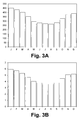
- FIGS. 3A and 3B are the present invention possible additional cooling of cooling water and the associated energy savings illustrated.
- FIG. 1 an air separation plant according to a particularly preferred embodiment of the invention is illustrated in the form of a schematic process flow diagram and denoted overall by 100.
- the air separation plant 100 is fed via a filter 101, a feed air stream a, compressed by a main air compressor 102 and cooled in a direct contact cooler 103, which among other things with a cooled water flow b from an evaporative cooler 104 is charged.
- the water flow b is thereby applied via a not separately designated pump to the direct contact cooler 103.
- water is supplied to the evaporative cooler 104 of a stream c, which can also be fed into the direct contact cooler 103 partially without prior cooling in the evaporative cooler 104.
- the direct contact cooler 103, a stream of water d is removed.
- the illustrated water flows b, c and d as well as the direct contact cooler 103 and the evaporative cooler 104 are incorporated into a cooling water circuit designated here by 10, which also contains any other water flows, not illustrated, Pumps, direct and indirect heat exchangers, etc. may include.
- the main air compressor 102 as illustrated here in a highly simplified manner, have at least two compressor stages 1 and 2, between which an intermediate cooling takes place by means of an intercooler 3.
- Typical main air compressors 102 of air separation plants include five to nine compressor stages and a corresponding number of intercoolers.
- the illustrated intercooler 3, which is set up for an indirect heat exchange, can be supplied with cooling water in the form of the flow s.
- the stream s may in particular be a partial stream of the stream c, that is, cooling water which also circulates in the cooling water circuit 10.
- more water streams can be fed at any point, for example, to compensate for evaporation losses, as illustrated here with the water flow e.
- At an appropriate point in the cooling water circuit 10 also cross connections between water streams, control devices, sensors and the like may be arranged.
- a recooling 11 Central component of the cooling water circuit 10 is a recooling 11, which is illustrated here as a wet cooler and may be formed, for example, as a cooling tower with forced ventilation. As mentioned, however, any other configurations are possible.
- the recooling plant 11 is set up for operation in accordance with a previously explained embodiment of the invention.
- the recooling plant 11 is supplied with a current f atmospheric air with a prevailing at the location of the air separation plant 100 Feuchtkugeltemperatur.
- the recooling plant 11 is designed, for example, such that it cools water of a water stream g to be cooled formed in the example shown from the water streams d and e to a temperature level which is at most 3 K above the wet bulb temperature of the air stream f. This is especially true when the wet bulb temperature of the airflow f is above 289K.
- a dried in the Adsorbersatz 50 compressed air flow is denoted by I.
- the compressed air flow I can be provided at a pressure which makes recompression necessary or dispensable (the latter in so-called high-air pressure processes).
- a partial flow m of the compressed air flow I is fed to a secondary compressor 107.
- a not separately designated aftercooler of the after-compressor 107 can also be cooled with water from the cooling water circuit 10.
- the partial flow m and a non-compressed partial flow n of the compressed air flow I are, according to the illustrated embodiment, supplied to a main heat exchanger 108 and taken from it at different temperature levels.
- the stream m can be expanded by means of a generator turbine 109 and, after being combined with the stream n, fed into a high-pressure column 111 of a distillation column system 110.
- Further partial streams of the compressed air stream I can be advantageously formed, cooled, re-compressed, expanded and likewise fed into columns of the distillation column system 110, for example a known, but not illustrated here, inductor current.
- the high-pressure column 111 together with a low-pressure column 112 forms a double-column system of known type.
- the distillation column system additionally comprises an argon enrichment column 113 and a pure argon column 114, which, however, need not be provided. Additional distillation columns may be provided.
- the distillation column system 110 may include, inter alia, a gaseous stream of nitrogen o, so-called impure nitrogen in the form of the stream p, from which, after heating in the main heat exchanger 108, the flow k and / or a stream q can be formed and supplied to the regeneration gas heater 106 or the evaporative cooler 104, and a liquid, oxygen-rich stream r can be removed.
- a cold, nitrogen-enriched stream can be used. Further currents are not explained in detail. Any streams may be heated in the main heat exchanger 108, pressurized upstream and / or downstream of the main heat exchanger 108, combined with other streams, and divided into sub-streams.
- FIG. 2 shows the average cooling water temperatures of the months of a year and the corresponding wet bulb temperatures for illustrating an embodiment of the invention.
- the cooling water temperature is plotted in K on the ordinate against the wet bulb temperature in K on the abscissa.
- the diagram shows the wet bulb temperature in the form of the data points 201, the cooling water temperature in the conventional design of a cooling tower formed as a cooling tower in the form of the data points 202 and the cooling water temperature in a design according to an embodiment of the invention in the form of the data points 203.
- the conventional design produces a cooling limit of 8K at a wet bulb temperature of 289K.
- the cooling margin has been reduced by five Kelvin to 3K.
- the use of a more efficient cooling tower and thus a lowering of the cooling limit temperature leads to two effects, on the one hand to colder cooling water and on the other hand to a lower relative distance of the cooling water temperature to the wet bulb temperature. This means that the efficiency loss of the cooling towers for a design with a smaller cooling boundary distance is generally lower in colder months.
- the reason for the lower efficiency loss of a large cooling tower in the cold months is the water-air ratio, which can be shifted in favor of the air.
- the water mass flow is the same for both types of cooling tower, it is crucial that with a large cooling tower with the same amount of cooling water, a larger amount of air can flow through the cooling tower, which absorbs the evaporating water and at the same time allows a stronger convective cooling. Especially at low air temperatures, where the air can absorb little water, this effect has a positive effect.
- FIGS. 3A and 3B are the possible additional cooling of cooling water according to the invention ( FIG. 3A ) and the associated energy savings ( FIG. 3B ).
- FIG. 3A is a temperature difference in K
- FIG. 3B an energy difference in kW on the ordinate against the months of January (J) to December (D) plotted on the abscissa.
- FIG. 3A results in an average of almost 5 K colder cooling water.
- the accordingly off FIG. 3B The apparent energy saving is between 270 and 450 kW per month, resulting in an average annual saving of 340 kW.
- the minimization of the compressor power consumption by 340 kW corresponds to 1.5% of the total compressor power consumption.
Abstract
Die Erfindung betrifft eine Luftzerlegungsanlage (100), in der zur Kühlung verdichteter Luft ein Kühlwasserkreislauf (10) mit einem Rückkühlwerk (11) bereitgestellt ist, wobei das Rückkühlwerk (11) dazu eingerichtet ist, Kühlwasser unter Verwendung von Kühlluft abzukühlen. Das Rückkühlwerk (11) ist derart ausgebildet ist, dass es zumindest bei einer Feuchtkugeltemperatur der Kühlluft von mehr als 289 K das Kühlwasser auf eine Temperatur abkühlt, die höchstens 3 K oberhalb der Feuchtkugeltemperatur liegt. Ein entsprechendes Betriebsverfahren und eine Steuereinrichtung sind ebenfalls Gegenstand der Erfindung.The invention relates to an air separation plant (100) in which compressed air for cooling a cooling water circuit (10) with a recooling plant (11) is provided, wherein the recooling plant (11) is adapted to cool cooling water using cooling air. The recooling plant (11) is designed such that, at least at a wet bulb temperature of the cooling air of more than 289 K, the cooling water cools to a temperature which is at most 3 K above the wet bulb temperature. A corresponding operating method and a control device are likewise provided by the invention.
Description
Die Erfindung betrifft eine Luftzerlegungsanlage, ein Verfahren zum Betreiben einer Luftzerlegungsanlage und eine Steuereinrichtung für eine derartige Luftzerlegungsanlage gemäß den jeweiligen Oberbegriffen der unabhängigen Patentansprüche.The invention relates to an air separation plant, a method for operating an air separation plant and a control device for such an air separation plant according to the respective preambles of the independent claims.
Die Herstellung von Luftprodukten in flüssigem oder gasförmigem Zustand durch Tieftemperaturzerlegung von Luft in Luftzerlegungsanlagen ist bekannt und beispielsweise bei
Luftzerlegungsanlagen weisen Destillationssäulensysteme auf, die beispielsweise als Zweisäulensysteme, insbesondere als klassische Linde-Doppelsäulensysteme, aber auch als Drei- oder Mehrsäulensysteme ausgebildet sein können. Neben den Destillationssäulen zur Gewinnung von Stickstoff und/oder Sauerstoff in flüssigem und/oder gasförmigem Zustand (beispielsweise flüssigem Sauerstoff, LOX, gasförmigem Sauerstoff, GOX, flüssigem Stickstoff, LIN und/oder gasförmigem Stickstoff, GAN), also den Destillationssäulen zur Stickstoff-Sauerstoff-Trennung, können Destillationssäulen zur Gewinnung weiterer Luftkomponenten, insbesondere der Edelgase Krypton, Xenon und/oder Argon, vorgesehen sein.Air separation plants have distillation column systems which can be designed, for example, as two-column systems, in particular as classic Linde double-column systems, but also as three-column or multi-column systems. In addition to the distillation columns for the recovery of nitrogen and / or oxygen in the liquid and / or gaseous state (for example, liquid oxygen, LOX, gaseous oxygen, GOX, liquid nitrogen, LIN and / or gaseous nitrogen, GAN), so the distillation columns for nitrogen-oxygen Separation, distillation columns can be provided for obtaining further air components, in particular the noble gases krypton, xenon and / or argon.
Die Destillationssäulensysteme von Luftzerlegungsanlagen werden bei unterschiedlichen Betriebsdrücken in ihren Destillationssäulen betrieben. Bekannte Doppelsäulensysteme weisen beispielsweise eine sogenannte (Hoch-)Drucksäule und eine sogenannte Niederdrucksäule auf. Der Betriebsdruck der Hochdrucksäule beträgt beispielsweise 4,3 bis 6,9 bar, insbesondere etwa 5,5 bar. Die Niederdrucksäule wird bei einem Betriebsdruck von beispielsweise 1,2 bis 1,7 bar, insbesondere etwa 1,4 bar, betrieben. Bei den hier angegebenen Drücken handelt es sich um Absolutdrücke im Sumpf entsprechender Destillationssäulen. Die genannten Drücke werden nachfolgend auch als "Destillationsdrücke" bezeichnet, weil bei ihnen die fraktionierte Destillation der jeweils eingespeisten Luft innerhalb der Destillationssäulen erfolgt. Dies schließt nicht aus, dass in einem Destillationssäulensystem an anderer Stelle auch noch andere Drücke vorliegen können.The distillation column systems of air separation plants are operated at different operating pressures in their distillation columns. Known double column systems have, for example, a so-called (high) pressure column and a so-called low-pressure column. The operating pressure of the high-pressure column is, for example, 4.3 to 6.9 bar, in particular about 5.5 bar. The low-pressure column is operated at an operating pressure of, for example, 1.2 to 1.7 bar, in particular about 1.4 bar. The pressures stated here are absolute pressures in Bottom of corresponding distillation columns. The pressures mentioned below are also referred to as "distillation pressures" because they are subjected to the fractional distillation of the respectively fed air within the distillation columns. This does not exclude that other pressures may be present elsewhere in a distillation column system.
In die Destillationssäulensysteme wird abgekühlte Druckluft (Einsatzluft) eingespeist, die mittels unterschiedlicher Luftverdichter oder Kombinationen aus unterschiedlichen Luftverdichtern (beispielsweise Hauptluftverdichtern und Nachverdichtern) auf Druck gebracht wird. Sämtliche Luftverdichter können mehrstufig ausgeführt sein. Da in einer Luftzerlegungsanlage etwa 95% des Energiebedarfs durch die genannten Luftverdichter entsteht, ist an dieser Stelle das größte Potential zur Einsparung vorhanden. Es besteht grundsätzlich der Bedarf nach energetisch effizienteren Verfahren und Anlagen zur Tieftemperaturzerlegung von Luft.In the distillation column systems cooled compressed air (feed air) is fed, which is brought by means of different air compressor or combinations of different air compressors (for example, main air compressors and booster) to pressure. All air compressors can be multi-stage. Since about 95% of the energy demand in an air separation plant is created by the air compressors mentioned, the greatest potential for saving is present here. There is a general need for more energy efficient processes and systems for the cryogenic separation of air.
Vor diesem Hintergrund stellt die vorliegende Erfindung eine Luftzerlegungsanlage, ein Verfahren zum Betreiben einer Luftzerlegungsanlage und eine Steuereinrichtung für eine derartige Luftzerlegungsanlage mit den jeweiligen Merkmalen der unabhängigen Patentansprüche bereit. Ausgestaltungen der Erfindung sind Gegenstand der abhängigen Patentansprüche und der nachfolgenden Beschreibung.Against this background, the present invention provides an air separation plant, a method for operating an air separation plant and a control device for such an air separation plant with the respective features of the independent claims. Embodiments of the invention are the subject of the dependent claims and the following description.
Die in den Luftverdichtern einer Luftzerlegungsanlage auf Druck gebrachte Einsatzluft wird typischerweise zur Abführung der bei der Verdichtung erzeugten Verdichtungswärme in unterschiedlich ausgeführten Kühleinrichtungen rückgekühlt. Diese Kühleinrichtungen umfassen beispielsweise Zwischen- und Nachkühler zwischen und stromab einer oder mehrerer Verdichtungsstufen, wie insoweit bekannt. Die Rückkühlung der in einem Hauptluftverdichter einer Luftzerlegungsanlage verdichteten Luft kann beispielsweise unter anderem in einem mit Kühlwasser aus einem Kühlwasserkreislauf betriebenen Direktkontaktkühler erfolgen. Zusätzlich können indirekte Wärmetauscher vorgesehen sein, die ebenfalls mit Kühlwasser betrieben werden können. Anschließend wird die Einsatzluft in bekannten Verfahren in einem Hauptwärmetauscher auf tiefkalte Temperaturen, d.h. Temperaturen von deutlich unter 0 °C, gebracht.The feed air pressurized in the air compressors of an air separation plant is typically recooled in various cooling devices to remove the heat of compression generated during the compression. These cooling devices include, for example, intermediate and aftercoolers between and downstream of one or more compression stages, as known in the art. The recooling of the air compressed in a main air compressor of an air separation plant can take place, for example, inter alia in a direct contact cooler operated with cooling water from a cooling water circuit. In addition, indirect heat exchangers can be provided, which can also be operated with cooling water. Subsequently, the feed air is brought in known processes in a main heat exchanger to cryogenic temperatures, ie temperatures of well below 0 ° C.
Die Rückkühlung erfolgt insbesondere zu dem Zweck, die Leistungsaufnahme der Luftverdichter zu verringern. Umso niedriger dabei die Kühlwassertemperatur ist, desto weiter kann die Prozessluft abgekühlt werden, was in einer geringeren Leistungsaufnahme der Luftverdichter resultiert. Zusätzlich tritt die Prozessluft dadurch auch bereits kälter in den eigentlichen Prozess der Luftzerlegung ein, unter anderem in den Hauptwärmetauscher. Daher ist die zu übertragende Wärme am Hauptwärmetauscher geringer, weshalb dieser mit einem geringeren Volumen ausgeführt werden kann und zusätzlich weniger Kälte durch Entspannung erzeugt werden muss. Eine Kälteerzeugung auf entsprechend niedrigen Temperaturniveaus von beispielsweise 120 bis 200 K hat beträchtliche exergetische Verluste zur Folge, die deutlich größer sind als bei der Kühlung von Kühlwasser, die bei nahezu Umgebungstemperatur erfolgt. Zudem sind größer auszuführende kryogene Bauteile (Wärmetauscher, Turbinen, Ventile) ausgesprochen kostenintensiv.The recooling is in particular for the purpose of reducing the power consumption of the air compressor. The lower the cooling water temperature is, the further the process air can be cooled, resulting in lower power consumption of the air compressors. In addition, the process air already enters the process of air separation colder, including in the main heat exchanger. Therefore, the heat to be transferred to the main heat exchanger is lower, which can therefore be carried out with a smaller volume and in addition less cold must be generated by relaxation. Refrigeration at correspondingly low temperature levels of, for example, 120 to 200 K results in considerable exergetic losses, which are significantly greater than in the cooling of cooling water, which occurs at near ambient temperature. In addition, larger-sized cryogenic components (heat exchangers, turbines, valves) are extremely costly.
Kühlwasserkreisläufe von Luftzerlegungsanlagen umfassen typischerweise Rückkühlwerke, in dem das erwärmte Kühlwasser des Kühlwasserkreislaufs mittels Kühlluft durch Verdunstungskühlung gekühlt wird. Insbesondere können als Rückkühlwerke Kühltürme bekannter Art eingesetzt werden, wie auch unten erläutert. Entsprechende Luftzerlegungsanlagen sind beispielsweise in der
Die Feuchtkugeltemperatur ist ein Maß für die Kühlgrenztemperatur, also die tiefste Temperatur, die das Kühlwasser durch direkte Verdunstungskühlung in einem entsprechenden Rückkühlwerk theoretisch erreichen kann. Bekanntermaßen steht die Wasserabgabe einer feuchten Oberfläche mit dem Wasseraufnahmevermögen der umgebenden Atmosphäre im Gleichgewicht. Aufgrund der Verdunstungskälte liegt die Kühlgrenztemperatur in Abhängigkeit von der relativen Luftfeuchte unterhalb der Lufttemperatur. Die Temperaturabsenkung bei der Verdunstungskühlung ist umso größer, je trockener die umgebende Luft ist. Der in einem entsprechenden Rückkühlwerk tatsächlich erreichte Temperaturunterschied zwischen der Feuchtkugeltemperatur und dem gekühlten Kühlwasser wird in der Fachwelt als Kühlgrenzabstand bezeichnet. Die Güte eines Rückkühlwerks, beispielsweise eines Kühlturms, wird durch die spezifische Packungsoberfläche, das Verhältnis von Flüssigkeit zu Gas und den Druckverlust bestimmt. Um einen geringen Kühlgrenzabstand zu erreichen, wie er aufgrund der vorstehend angegebenen Vorteile einer geringeren Kühlwassertemperatur grundsätzlich wünschenswert ist, fallen daher grundsätzlich höhere Investitionskosten zur Erstellung von Rückkühlwerken an.The wet bulb temperature is a measure of the cooling limit temperature, ie the lowest temperature that the cooling water can theoretically achieve by direct evaporative cooling in a corresponding recooling plant. As is known, the release of water from a moist surface is in equilibrium with the water absorption capacity of the surrounding atmosphere. Due to the evaporative cooling, the cooling limit temperature is dependent on the relative humidity below the air temperature. The lower the temperature in the evaporative cooling, the drier the surrounding air is. The temperature difference actually reached in a corresponding recooling plant between the Wet bulb temperature and the cooled cooling water is referred to in the art as the cooling limit distance. The quality of a recooling plant, for example a cooling tower, is determined by the specific packing surface, the ratio of liquid to gas and the pressure loss. In order to achieve a low cooling limit distance, as it is basically desirable due to the above-mentioned advantages of a lower cooling water temperature, therefore, in principle, higher investment costs for the preparation of recooling come on.
Der verwendete Kühlgrenzabstand richtet sich daher nach wirtschaftlichen Erwägungen, die die genannten Aspekte einbeziehen. In bisherigen Publikationen zu zwangsbelüfteten Rückkühlwerken in Industrieanlagen wird meist ein Kühlgrenzabstand von 3 bis 5 K als ökonomisch angegeben, siehe beispielsweise Z.
Zu weiteren Details bezüglich Rückkühlwerken und deren Auslegung sei auf einschlägige Fachliteratur, beispielsweise H.-D. Held, H.-G. Schnell, Kühlwasser: Verfahren der Systeme der Aufbereitung und Kühlung von
Erfindungsgemäß wurde überraschend und im Gegensatz zur herrschenden Meinung zu zwangsbelüfteten Rückkühlwerken (siehe beispielsweise die bereits zitierte Veröffentlichung Z.K. Morvay & D.D. Gvozdenac) erkannt, dass, bezogen auf die Gesamtbetriebskosten (Total Cost of Ownership, TCO), ein Kühlgrenzabstand unter 3 K für eine Vielzahl von Luftzerlegungsanlagen wirtschaftliche Vorteile bietet. Dabei sollte der Kühlgrenzabstand in Abhängigkeit des Kapitalwerts (in Geldeinheiten pro kW, Net Present Value, NPV) bei gegebener Feuchtkugeltemperatur unter Designbedingungen ausgewählt werden. Anlagen mit identischem Kapitalwert können somit unabhängig von den jeweiligen Umgebungsbedingungen ein Rückkühlwerk mit gleicher spezifisch abgeführter Wärmemenge erhalten. Dies ermöglicht eine systematische Auswahl der Kühltürme in Abhängigkeit des Kapitalwerts. Wie erwähnt, wird nach herrschender Meinung, insbesondere für reale industrielle Anwendungen wie Luftzerlegungsanlagen, ein Kühlgrenzabstand deutlich oberhalb von 3 K als sinnvoll angesehen. In der mehrfach zitierten Veröffentlichung von Z.K. Morvay & D.D. Gvozdenac wird eine Reihe von Effizienzverbesserungen vorgeschlagen, aber gerade nicht die Absenkung des Kühlgrenzabstands.According to the invention was surprisingly and in contrast to the prevailing opinion on forced-ventilated recooling (see, for example, already cited publication ZK Morvay & DD Gvozdenac) recognized that, based on the total cost of ownership (TCO), a cooling limit distance below 3 K for a variety offers economic benefits from air separation plants. In this case, the cooling limit distance should be selected depending on the capital value (in monetary units per kW, net present value, NPV) for a given wet bulb temperature under design conditions. Systems with the same net present value can thus receive a recooling unit with the same amount of specific heat dissipated regardless of the respective ambient conditions. This allows a systematic selection of the cooling towers depending on the net present value. As mentioned, according to prevailing opinion, especially for real industrial applications such as air separation plants, a cooling boundary distance well above 3 K is considered useful. In the cited publication by Z.K. Morvay & D.D. Gvozdenac proposes a number of efficiency improvements, but not the lowering of the cooling margin.
Die vorliegende Erfindung schlägt daher eine Luftzerlegungsanlage vor, in der zur Kühlung verdichteter Luft ein Kühlwasserkreislauf mit einem Rückkühlwerk bereitgestellt ist, wobei das Rückkühlwerk dazu eingerichtet ist, Kühlwasser unter Verwendung von Kühlluft abzukühlen. Die erfindungsgemäße Luftzerlegungsanlage zeichnet sich dadurch aus, dass das Rückkühlwerk dazu eingerichtet ist, dass es zumindest bei einer Feuchtkugeltemperatur der Kühlluft von mehr als 289 K das Kühlwasser auf eine Temperatur abkühlt, die höchstens 3 K oberhalb der Feuchtkugeltemperatur liegt. Mit anderen Worten wird mittels des Rückkühlwerks der erfindungsgemäßen Luftzerlegungsanlage ein Kühlgrenzabstand von 3 K oder weniger, insbesondere auch 2 K oder weniger oder 1 K oder weniger, unter den genannten Bedingungen erzielt.The present invention therefore proposes an air separation plant in which a cooling water circuit with a recooling plant is provided for cooling compressed air, wherein the recooling plant is adapted to cool cooling water using cooling air. The air separation plant according to the invention is characterized in that the recooling plant is set up to cool the cooling water to a temperature at least 3 K above that at least at a wet bulb temperature of the cooling air of more than 289 K Wet bulb temperature is. In other words, by means of the recooling plant of the air separation plant according to the invention, a cooling boundary distance of 3 K or less, in particular also 2 K or less or 1 K or less, is achieved under the stated conditions.
Wie sich im Rahmen der vorliegenden Erfindung herausgestellt hat, ist die häufig in der Literatur vorzufindende Aussage, Rückkühlwerke mit einem Kühlgrenzabstand von weniger als 2 K seien technisch nicht realisierbar, falsch. Ebenso wurde die üblicherweise getroffene Verallgemeinerung, lediglich ein Kühlgrenzabstand von 3 bis 5 K wäre ökonomisch sinnvoll, als nicht richtig erkannt. Eine Angabe zur Realisierbarkeit sowie des ökonomischen Nutzens von Rückkühlwerken mit einem festgelegtem Kühlgrenzabstand unter Missachtung der Feuchtkugeltemperatur ist, wie im Rahmen der vorliegenden Erfindung erkannt wurde, nicht aussagekräftig.As has been found in the context of the present invention, the frequently found in the literature statement, recooling units with a cooling limit distance of less than 2 K are not technically feasible, wrong. Likewise, the commonly used generalization, only a cooling limit distance of 3 to 5 K would be economically useful, as not recognized correctly. An indication of the feasibility as well as the economic benefit of recooling plants with a fixed cooling boundary distance in disregard of the wet bulb temperature, as recognized in the context of the present invention, not meaningful.
Durch eine Verringerung des Kühlgrenzabstands auf Werte unter 3 K kann, wie erfindungsgemäß erkannt und nachfolgend dokumentiert, bei mittleren und hohen Feuchtkugeltemperaturen von mehr als 289 K die Wirtschaftlichkeit von Luftzerlegungsanlagen deutlich gesteigert werden. Die vorliegende Erfindung beruht damit auf einer wesentlichen Neubewertung zum Stand des Wissens der Kühlturmauslegung in Bezug auf Luftzerlegungsprozesse und kryogene Prozesse im Allgemeinen.By reducing the cooling boundary distance to values below 3 K, the efficiency of air separation plants can be markedly increased at medium and high wet bulb temperatures of more than 289 K as recognized and subsequently documented in accordance with the invention. The present invention is thus based on a substantial revaluation of the state of knowledge of cooling tower design with respect to air separation processes and cryogenic processes in general.
Im Rahmen der vorliegenden Erfindung konnte gezeigt werden, dass ein effizienter arbeitendes Rückkühlwerk, das das Kühlwasser sehr nahe an das thermodynamisch mögliche Minimum (also die Feuchtkugeltemperatur) rückkühlt, eine signifikante Energieeinsparung der Luftzerlegungsanlage ermöglicht. Dies wird in den
Im Rahmen einer Wirtschaftlichkeitsbetrachtung kann beispielsweise ein konventionell ausgelegtes Rückkühlwerk gegenüber einem erfindungsgemäß ausgelegten Rückkühlwerk entsprechend den
Im Rahmen der vorliegenden Erfindung wird vorteilhafterweise ein Rückkühlwerk eingesetzt, das derart ausgebildet ist, dass es das Kühlwasser auf eine Temperatur abkühlt, die mindestens 0,5 K, beispielsweise aber auch mindestens 1 K, mindestens 1,5 K oder mindestens 2 K, oberhalb der Feuchtkugeltemperatur liegt. Ein optimaler Wertebereich für minimale und maximale Kühlgrenzabstände ergibt sich aus den obigen Überlegungen.In the context of the present invention, a recooling unit is advantageously used which is designed such that it cools the cooling water to a temperature which is at least 0.5 K, for example but also at least 1 K, at least 1.5 K or at least 2 K above the wet bulb temperature is. An optimal one The range of values for minimum and maximum cooling limit distances results from the above considerations.
Grundsätzlich kann eine erfindungsgemäße Luftzerlegungsanlage ein beliebig ausgebildetes Rückkühlwerk aufweisen, insbesondere umfasst dieses jedoch einen Kühlturm. Insbesondere Rückkühlwerke bzw. Kühltürme mit Zwangsbelüftung werden bei Luftzerlegungsanlagen vielfach eingesetzt und sind bewährt und wartungsarm. Ein Kühlturm ermöglicht insbesondere eine vergleichsweise einfache Verringerung der Kühlgrenztemperatur durch Vergrößerung, wie zuvor erläutert.In principle, an air separation plant according to the invention can have an optionally designed recooling plant, but in particular this comprises a cooling tower. In particular, recooling or cooling towers with forced ventilation are often used in air separation plants and are proven and low maintenance. In particular, a cooling tower allows a comparatively simple reduction of the cooling limit temperature by enlargement, as explained above.
Wie bereits zuvor erwähnt, eignet sich das unter Verwendung des Rückkühlwerks gekühlte Kühlwasser insbesondere zur Nachkühlung stromab von Verdichtern in einer entsprechenden Luftzerlegungsanlage, so dass der Kühlwasserkreislauf einer erfindungsgemäßen Luftzerlegungsanlage vorteilhafterweise einen Wärmetauscher umfasst, der stromab eines Luftverdichters oder einer Stufe eines entsprechenden Luftverdichters ist. Unter einem "Luftverdichter" wird hier eine ein- oder mehrstufige Anordnung verstanden, die zur Druckerhöhung eingerichtet ist, insbesondere ein Radial- bzw. Turboverdichter. Ein oder mehrere Wärmetauscher können sich stromab einer oder mehrerer Verdichterstufen befinden.As already mentioned above, the cooling water cooled using the recooling plant is suitable in particular for aftercooling downstream of compressors in a corresponding air separation plant, so that the cooling water circuit of an air separation plant according to the invention advantageously comprises a heat exchanger downstream of an air compressor or a stage of a corresponding air compressor. An "air compressor" is here understood to mean a single-stage or multi-stage arrangement which is set up to increase the pressure, in particular a radial or turbo compressor. One or more heat exchangers may be downstream of one or more compressor stages.
Im Rahmen der vorliegenden Erfindung kann eine Kühlzonenbreite des Rückkühlwerks insbesondere von 5 bis 25 K, insbesondere von 8 bis 12 K, typischerweise ca. 10 K betragen.In the context of the present invention, a cooling zone width of the recooling plant can be in particular from 5 to 25 K, in particular from 8 to 12 K, typically about 10 K.
Die Erfindung erstreckt sich ferner auf ein Verfahren zum Betreiben einer Luftzerlegungsanlage, in der zur Kühlung verdichteter Luft ein Kühlwasserkreislauf mit einem Rückkühlwerk bereitgestellt ist, wobei das Rückkühlwerk dazu eingerichtet ist, Kühlwasser unter Verwendung von Kühlluft abzukühlen. Das erfindungsgemäße Verfahren zeichnet sich dadurch aus, dass das Rückkühlwerk derart betrieben wird, dass es zumindest bei einer Feuchtkugeltemperatur der Kühlluft von mehr als 289 K das Kühlwasser auf eine Temperatur abkühlt, die höchstens 3 K oberhalb der Feuchtkugeltemperatur liegt. Ebenso erstreckt sich die vorliegende Erfindung auf eine Steuereinrichtung einer Luftzerlegungsanlage, die dafür eingerichtet ist, ein entsprechendes Verfahren durchzuführen. In beiden Fällen sei bezüglich Merkmalen und Vorteilen auf die obigen Erläuterungen verwiesen.The invention further extends to a method for operating an air separation plant, in which a cooling water circuit is provided with a recooling unit for cooling compressed air, wherein the recooling unit is adapted to cool cooling water using cooling air. The inventive method is characterized in that the recooling is operated such that it cools the cooling water to a temperature which is at most 3 K above the wet bulb temperature at least at a wet bulb temperature of the cooling air of more than 289 K. Likewise, the present invention extends to a control device of an air separation plant, which is adapted to perform a corresponding method. In both cases reference should be made to the above explanations regarding features and advantages.
Die Erfindung wird nachfolgend unter Bezugnahme auf die beigefügten Zeichnungen näher erläutert, die bevorzugte Ausführungsformen der Erfindung zeigen.The invention will be explained in more detail below with reference to the accompanying drawings which show preferred embodiments of the invention.
In
In
In
In
Der Luftzerlegungsanlage 100 wird über ein Filter 101 ein Einsatzluftstrom a zugeführt, mittels eines Hauptluftverdichters 102 verdichtet und in einem Direktkontaktkühler 103 gekühlt, welcher unter anderem mit einem abgekühlten Wasserstrom b aus einem Verdunstungskühler 104 beschickt wird. Der Wasserstrom b wird dabei über eine nicht gesondert bezeichnete Pumpe auf den Direktkontaktkühler 103 aufgegeben. Zur Bereitstellung des gekühlten Wasserstroms b wird dem Verdunstungskühler 104 Wasser eines Stroms c zugeführt, welches teilweise auch ohne vorige Kühlung in dem Verdunstungskühler 104 in den Direktkontaktkühler 103 eingespeist werden kann. Dem Direktkontaktkühler 103 wird ein Wasserstrom d entnommen.The
Die dargestellten Wasserströme b, c und d sowie der Direktkontaktkühler 103 und der Verdunstungskühler 104 sind in einen hier mit 10 bezeichneten Kühlwasserkreislauf eingebunden, der auch beliebige weitere, nicht veranschaulichte Wasserströme, Pumpen, direkte und indirekte Wärmetauscher usw. umfassen kann. Beispielsweise kann der Hauptluftverdichter 102, wie hier stark vereinfacht veranschaulicht, zumindest zwei Verdichterstufen 1 und 2 aufweisen, zwischen welchen eine Zwischenkühlung mittels eines Zwischenkühlers 3 erfolgt. Typische Hauptluftverdichter 102 von Luftzerlegungsanlagen umfassen fünf bis neun Verdichterstufen und eine entsprechende Anzahl an Zwischenkühlern. Dem veranschaulichten Zwischenkühler 3, der für einen indirekten Wärmetausch eingerichtet ist, kann Kühlwasser in Form des Stroms s zugeführt werden. Bei dem Strom s kann es sich insbesondere um einen Teilstrom des Stroms c handeln, also Kühlwasser, das ebenfalls in dem Kühlwasserkreislauf 10 zirkuliert. Entsprechendes gilt für weitere (Nach-)Kühler wie unten erläutert. In den Kühlwasserkreislauf 10 können an beliebiger Stelle weitere Wasserströme eingespeist werden, beispielsweise um Verdunstungsverluste auszugleichen, wie hier mit dem Wasserstrom e veranschaulicht. An zweckmäßiger Stelle in dem Kühlwasserkreislauf 10 können ferner Querverbindungen zwischen Wasserströmen, Regeleinrichtungen, Messfühler und dergleichen angeordnet sein.The illustrated water flows b, c and d as well as the
Zentrale Komponente des Kühlwasserkreislaufs 10 ist ein Rückkühlwerk 11, das hier als Nasskühler veranschaulicht ist und beispielsweise als Kühlturm mit Zwangsbelüftung ausgebildet sein kann. Wie erwähnt, sind jedoch auch beliebige andere Ausgestaltungen möglich. Das Rückkühlwerk 11 ist für einen Betrieb gemäß einer zuvor erläuterten Ausführungsform der Erfindung eingerichtet. Dem Rückkühlwerk 11 wird ein Strom f atmosphärischer Luft mit einer am Standort der Luftzerlegungsanlage 100 herrschenden Feuchtkugeltemperatur zugeführt. Das Rückkühlwerk 11 ist beispielsweise derart ausgebildet, dass es Wasser eines im dargestellten Beispiel aus den Wasserströmen d und e gebildeten zu kühlenden Wasserstroms g bis auf ein Temperaturniveau abkühlt, das höchstens 3 K oberhalb der Feuchtkugeltemperatur des Luftstroms f liegt. Dies gilt insbesondere dann, wenn die Feuchtkugeltemperatur des Luftstroms f oberhalb von 289 K liegt.Central component of the cooling
Die weitere Bearbeitung des verdichteten und gekühlten Einsatzluftstroms a, der nun mit h bezeichnet ist, entspricht weitgehend jener in herkömmlichen Luftzerlegungsanlagen, beispielsweise in einer Luftzerlegungsanlage, wie sie bei H.-
- Der verdichtete und gekühlte Einsatzluftstrom h, wird einem
Adsorbersatz 105 zugeführt, der im Wechsel betrieb betriebene Adsorberbehälter umfasst und mittels eines Regeneriergasstroms i regeneriert werden kann. Der Regeneriergasstrom i kann mittels einer elektrisch und/oder mitDampf betriebenen Regeneriergasheizung 106, erwärmt werden. Zur Bereitstellung des Regeneriergasstroms i kann ein Strom k verwendet werden, dessen Bereitstellung unten näher erläutert wird.
- The compressed and cooled feed air stream h is fed to an
adsorber set 105, which comprises alternately operated adsorber vessels and can be regenerated by means of a regeneration gas stream i. The regeneration gas stream i can be heated by means of an electrically and / or steam-operatedregeneration gas heater 106. To provide the Regeneriergasstroms i, a current k can be used, the provision of which is explained in more detail below.
Ein in dem Adsorbersatz 50 getrockneter Druckluftstrom ist mit I bezeichnet. Je nach Ausführungsform der Luftzerlegungsanlage 100 kann der Druckluftstrom I auf einem Druck bereitgestellt werden, der eine Nachverdichtung erforderlich oder verzichtbar macht (letzteres bei sogenannten High Air Pressure-Verfahren). Im dargestellten Beispiel wird ein Teilstrom m des Druckluftstroms I einem Nachverdichter 107 zugeführt. Ein nicht gesondert bezeichneter Nachkühler des Nachverdichters 107 kann ebenfalls mit Wasser aus dem Kühlwasserkreislauf 10 gekühlt werden.A dried in the
Der Teilstrom m und ein nicht nachverdichteter Teilstrom n des Druckluftstroms I werden gemäß der dargestellten Ausführungsform einem Hauptwärmetauscher 108 zugeführt und diesem auf unterschiedlichen Temperaturniveaus entnommen. Der Strom m kann mittels einer Generatorturbine 109 entspannt und nach Vereinigung mit dem Strom n in eine Hochdrucksäule 111 eines Destillationssäulensystems 110 eingespeist werden. Weitere Teilströme des Druckluftstroms I können in zweckmäßiger Weise gebildet, abgekühlt, nachverdichtet, entspannt und ebenfalls in Säulen des Destillationssäulensystems 110 eingespeist werden, beispielsweise ein bekannter, hier aber nicht veranschaulichter, Drosselstrom.The partial flow m and a non-compressed partial flow n of the compressed air flow I are, according to the illustrated embodiment, supplied to a
Die Hochdrucksäule 111 bildet zusammen mit einer Niederdrucksäule 112 ein Doppelsäulensystem bekannter Art. Im dargestellten Beispiel umfasst das Destillationssäulensystem zusätzlich eine Argonanreicherungssäule 113 und eine Reinargonsäule 114, die jedoch nicht vorgesehen sein müssen. Weitere Destillationssäulen können bereitgestellt sein.The high-
Der Betrieb des Destillationssäulensystems 110 ist bekannt und wird daher nicht erläutert. Im dargestellten Beispiel können dem Destillationssäulensystem 110 unter anderem ein gasförmiger Stickstoffstrom o, sogenannter Unreinstickstoff in Form des Stroms p, aus dem nach Erwärmung in dem Hauptwärmetauscher 108 der Strom k und/oder ein Strom q gebildet und der Regeneriergasheizung 106 bzw. dem Verdunstungskühler 104 zugeführt werden können, und ein flüssiger, sauerstoffreicher Strom r entnommen werden. Anstelle des Stroms q kann auch beispielsweise ein kalter, stickstoffangereicherter Strom zum Einsatz kommen. Weitere Ströme werden nicht im Detail erläutert. Beliebige Ströme können in dem Hauptwärmetauscher 108 erwärmt, stromauf und/oder stromab des Hauptwärmetauschers 108 verdichtet bzw. druckbeaufschlagt, mit anderen Strömen vereinigt und in Teilströme aufgeteilt werden.The operation of the
In
Die konventionelle Auslegung bewirkt bei einer Feuchtkugeltemperatur von 289 K einen Kühlgrenzabstand von 8 K. Gemäß der dargestellten Ausführungsform der Erfindung wurde der Kühlgrenzabstand um fünf Kelvin auf 3 K verringert. Die Verwendung eines effizienteren Kühlturms und somit ein Absenken der Kühlgrenztemperatur führt zu zwei Effekten, nämlich einerseits zu kälterem Kühlwasser und andererseits zu einem geringeren relativen Abstand der Kühlwassertemperatur zur Feuchtkugeltemperatur. Dies bedeutet, dass der Wirkungsgradverlust der Kühltürme für ein Design mit kleinerem Kühlgrenzabstand grundsätzlich in kälteren Monaten geringer ist. Der Grund für den geringeren Wirkungsgradverlust eines großen Kühlturms in den kalten Monaten liegt im Wasser-Luftverhältnis, das zugunsten der Luft verschoben werden kann. Der Wassermassenstrom ist für beide Kühlturmvarianten gleich groß, entscheidend ist, dass bei einem großen Kühlturm bei gleicher Kühlwassermenge eine größere Luftmenge durch den Kühlturm strömen kann, die das verdampfende Wasser aufnimmt und gleichzeitig eine stärkere konvektive Kühlung ermöglicht. Gerade bei niedrigen Lufttemperaturen, bei denen die Luft wenig Wasser aufnehmen kann, wirkt sich dieser Effekt positiv aus.The conventional design produces a cooling limit of 8K at a wet bulb temperature of 289K. According to the illustrated embodiment of the invention, the cooling margin has been reduced by five Kelvin to 3K. The use of a more efficient cooling tower and thus a lowering of the cooling limit temperature leads to two effects, on the one hand to colder cooling water and on the other hand to a lower relative distance of the cooling water temperature to the wet bulb temperature. This means that the efficiency loss of the cooling towers for a design with a smaller cooling boundary distance is generally lower in colder months. The reason for the lower efficiency loss of a large cooling tower in the cold months is the water-air ratio, which can be shifted in favor of the air. The water mass flow is the same for both types of cooling tower, it is crucial that with a large cooling tower with the same amount of cooling water, a larger amount of air can flow through the cooling tower, which absorbs the evaporating water and at the same time allows a stronger convective cooling. Especially at low air temperatures, where the air can absorb little water, this effect has a positive effect.
In
Wie aus
Claims (8)
Applications Claiming Priority (1)
| Application Number | Priority Date | Filing Date | Title |
|---|---|---|---|
| EP15002236 | 2015-07-28 |
Publications (1)
| Publication Number | Publication Date |
|---|---|
| EP3124902A1 true EP3124902A1 (en) | 2017-02-01 |
Family
ID=53785385
Family Applications (1)
| Application Number | Title | Priority Date | Filing Date |
|---|---|---|---|
| EP16001509.5A Withdrawn EP3124902A1 (en) | 2015-07-28 | 2016-07-07 | Air separation facility, operating method and control device |
Country Status (4)
| Country | Link |
|---|---|
| US (1) | US20170030635A1 (en) |
| EP (1) | EP3124902A1 (en) |
| CN (1) | CN106642993A (en) |
| TW (1) | TW201718066A (en) |
Families Citing this family (2)
| Publication number | Priority date | Publication date | Assignee | Title |
|---|---|---|---|---|
| PL3410050T3 (en) * | 2017-06-02 | 2019-10-31 | Linde Ag | Method for producing one or more air products and air separation system |
| CN110688740A (en) * | 2019-09-10 | 2020-01-14 | 天津大学 | Modelica combined simulation optimization-based cold water machine room model calibration method |
Citations (3)
| Publication number | Priority date | Publication date | Assignee | Title |
|---|---|---|---|---|
| JPS5885093A (en) | 1981-11-16 | 1983-05-21 | Hitachi Ltd | Apparatus for re-cooling of raw air cooling water |
| JPS6470635A (en) * | 1987-09-09 | 1989-03-16 | Nec Corp | Cooling water temperature control device |
| EP0644390A1 (en) | 1993-09-21 | 1995-03-22 | L'air Liquide, Societe Anonyme Pour L'etude Et L'exploitation Des Procedes Georges Claude | Gas compression process and assembly |
Family Cites Families (3)
| Publication number | Priority date | Publication date | Assignee | Title |
|---|---|---|---|---|
| FR2712509B1 (en) * | 1993-11-19 | 1995-12-22 | Air Liquide | Process and installation for air distillation. |
| JP3538338B2 (en) * | 1999-05-21 | 2004-06-14 | 株式会社神戸製鋼所 | Oxygen gas production method |
| CN203375800U (en) * | 2013-06-24 | 2014-01-01 | 湖南宜化化工有限责任公司 | Deep cooling air separation oxygen generation system by adoption of synthesis ammonia process |
-
2016
- 2016-07-07 EP EP16001509.5A patent/EP3124902A1/en not_active Withdrawn
- 2016-07-19 US US15/213,784 patent/US20170030635A1/en not_active Abandoned
- 2016-07-27 TW TW105123780A patent/TW201718066A/en unknown
- 2016-07-27 CN CN201610861067.3A patent/CN106642993A/en active Pending
Patent Citations (3)
| Publication number | Priority date | Publication date | Assignee | Title |
|---|---|---|---|---|
| JPS5885093A (en) | 1981-11-16 | 1983-05-21 | Hitachi Ltd | Apparatus for re-cooling of raw air cooling water |
| JPS6470635A (en) * | 1987-09-09 | 1989-03-16 | Nec Corp | Cooling water temperature control device |
| EP0644390A1 (en) | 1993-09-21 | 1995-03-22 | L'air Liquide, Societe Anonyme Pour L'etude Et L'exploitation Des Procedes Georges Claude | Gas compression process and assembly |
Non-Patent Citations (12)
| Title |
|---|
| "Industrial Gases Processing", 2006, WILEY-VCH |
| "Industrial Gases Processing", 2006, WILEY-VCH, article "Cryogenic Rectification" |
| ADVANTAGE-ENGINEERING: "SUBJECT: UNDERSTANDING THE ASPECTS THAT AFFECT COOLING TOWER PERFORMANCE", 6 October 2004 (2004-10-06), pages 1 - 2, XP055244186, Retrieved from the Internet <URL:http://www.advantageengineering.com/fyi/273/pdf/advantageFYI273.pdf> [retrieved on 20160125] * |
| B. BUECKER: "Power Plant Water Chemistry: A Practical Guide", 1997, PENNWELL |
| H. RIETSCHEL; K. FITZNER; RAUMKLIMATECHNIK: "Raumluft und Raumkühltechnik", 2008, SPRINGER |
| H.-D. HELD; H.-G. SCHNELL: "Kühlwasser: Verfahren der Systeme der Aufbereitung und Kühlung von Süßwasser, Brackwasser-und Meerwasser zur industriellen Kühlung", 2000, VULKAN |
| J.J. MCKETTA: "Encyclopedia of Chemical Processing and Design", vol. 58, 1997, MARCEL DEKKER |
| P.N. ANANTHANARAYANAN: "Basic Refrigeration and Air Conditioning", 2006, TATA MCGRAW-HILL |
| V. D. PAPAEFTHIMIOU ET AL: "Thermodynamic study of wet cooling tower performance", INTERNATIONAL JOURNAL OF ENERGY RESEARCH, vol. 30, no. 6, 1 May 2006 (2006-05-01), GB, pages 411 - 426, XP055243949, ISSN: 0363-907X, DOI: 10.1002/er.1158 * |
| V.D. PAPAEFTHIMIOU ET AL.: "Thermodynamic Study of Wet Cooling Tower Performance", INT. J. ENERG. RES, vol. 30, no. 6, 2006, pages 411 - 426, XP055243949, DOI: doi:10.1002/er.1158 |
| Z K MORVAY ET AL: "APPLIED INDUSTRIAL ENERGY AND ENVIRONMENTAL MANAGEMENT Part III: FUNDAMENTALS FOR ANALYSIS AND CALCULATION OF ENERGY AND ENVIRONMENTAL PERFORMANCE 1 Applied Industrial Energy and Environmental Management", 8 October 2008 (2008-10-08), pages 1 - 34, XP055243963, Retrieved from the Internet <URL:http://www.wiley.com/legacy/wileychi/morvayindustrial/supp/toolbox12.pdf> [retrieved on 20160122] * |
| Z. K. MORVAY; D.D. GVOZDENAC: "Applied Industrial Energy and Environmental Management, Part III: Toolbox - Fundamentals for Analysis and Calculation of Energy and Environmental Performance, Toolbox 12: Cooling Towers", 2008, WILEY |
Also Published As
| Publication number | Publication date |
|---|---|
| TW201718066A (en) | 2017-06-01 |
| US20170030635A1 (en) | 2017-02-02 |
| CN106642993A (en) | 2017-05-10 |
Similar Documents
| Publication | Publication Date | Title |
|---|---|---|
| EP2980514A1 (en) | Method for the low-temperature decomposition of air and air separation plant | |
| EP3179187B1 (en) | Method for obtaining a liquid and a gaseous oxygen-rich air product in an air breakdown apparatus and air breakdown apparatus | |
| EP0093448A2 (en) | Process and apparatus for obtaining gaseous oxygen at elevated pressure | |
| DE10139727A1 (en) | Method and device for obtaining a printed product by low-temperature separation of air | |
| DE102007031765A1 (en) | Process for the cryogenic separation of air | |
| DE102010052544A1 (en) | Process for obtaining a gaseous product by cryogenic separation of air | |
| EP1074805B1 (en) | Process for producing oxygen under pressure and device therefor | |
| DE69814519T2 (en) | Cryogenic process with double acid and external evaporator condenser for an oxygen and nitrogen mixture | |
| EP3410050A1 (en) | Method for producing one or more air products and air separation system | |
| EP2963369B1 (en) | Method and device for the cryogenic decomposition of air | |
| EP3290843A2 (en) | Method and device for extracting pressurised nitrogen and pressurised nitrogen by cryogenic decomposition of air | |
| DE19951521A1 (en) | Recovering pressurized product by low temperature decomposition of air in rectification system comprises cold compressing heat carrier stream before introducing into mixing column | |
| EP3124902A1 (en) | Air separation facility, operating method and control device | |
| DE19537913A1 (en) | Triple column process for the low temperature separation of air | |
| DE1159971B (en) | Process for the production of gaseous and pressurized oxygen by decomposing air | |
| EP2551619A1 (en) | Method and device for extracting pressurised oxygen and pressurised nitrogen by cryogenic decomposition of air | |
| EP2914913B1 (en) | Process for the low-temperature separation of air in an air separation plant and air separation plant | |
| DE1082925B (en) | Process and device for cleaning and keeping the hydrogen cold cycle clean for low-temperature rectification systems | |
| EP3671085A1 (en) | Assembly and method for recovering compression heat from the air which is compressed and processed in an air processing system | |
| EP2906889B1 (en) | Process and facility for generating liquid and gaseous oxygen products by low-temperature separation of air | |
| DE202018006161U1 (en) | Plant for the cryogenic separation of air | |
| DE102013019147A1 (en) | Process for obtaining at least one oxygen product in an air separation plant and air separation plant | |
| EP3870917B1 (en) | Method and installation for cryogenic separation of air | |
| DE102016013091A1 (en) | Method and system for purifying a gas | |
| EP3255366A1 (en) | Method and device for generating a gaseous compressed oxygen product |
Legal Events
| Date | Code | Title | Description |
|---|---|---|---|
| PUAI | Public reference made under article 153(3) epc to a published international application that has entered the european phase |
Free format text: ORIGINAL CODE: 0009012 |
|
| STAA | Information on the status of an ep patent application or granted ep patent |
Free format text: STATUS: THE APPLICATION HAS BEEN PUBLISHED |
|
| AK | Designated contracting states |
Kind code of ref document: A1 Designated state(s): AL AT BE BG CH CY CZ DE DK EE ES FI FR GB GR HR HU IE IS IT LI LT LU LV MC MK MT NL NO PL PT RO RS SE SI SK SM TR |
|
| AX | Request for extension of the european patent |
Extension state: BA ME |
|
| STAA | Information on the status of an ep patent application or granted ep patent |
Free format text: STATUS: REQUEST FOR EXAMINATION WAS MADE |
|
| 17P | Request for examination filed |
Effective date: 20170627 |
|
| RBV | Designated contracting states (corrected) |
Designated state(s): AL AT BE BG CH CY CZ DE DK EE ES FI FR GB GR HR HU IE IS IT LI LT LU LV MC MK MT NL NO PL PT RO RS SE SI SK SM TR |
|
| RAP1 | Party data changed (applicant data changed or rights of an application transferred) |
Owner name: LINDE GMBH |
|
| STAA | Information on the status of an ep patent application or granted ep patent |
Free format text: STATUS: THE APPLICATION IS DEEMED TO BE WITHDRAWN |
|
| 18D | Application deemed to be withdrawn |
Effective date: 20210202 |