EP3124343A1 - Straddle-type vehicle - Google Patents
Straddle-type vehicle Download PDFInfo
- Publication number
- EP3124343A1 EP3124343A1 EP16181534.5A EP16181534A EP3124343A1 EP 3124343 A1 EP3124343 A1 EP 3124343A1 EP 16181534 A EP16181534 A EP 16181534A EP 3124343 A1 EP3124343 A1 EP 3124343A1
- Authority
- EP
- European Patent Office
- Prior art keywords
- brake
- pipe
- supporter
- straddle
- top bridge
- Prior art date
- Legal status (The legal status is an assumption and is not a legal conclusion. Google has not performed a legal analysis and makes no representation as to the accuracy of the status listed.)
- Granted
Links
Images


Classifications
-
- B—PERFORMING OPERATIONS; TRANSPORTING
- B62—LAND VEHICLES FOR TRAVELLING OTHERWISE THAN ON RAILS
- B62L—BRAKES SPECIALLY ADAPTED FOR CYCLES
- B62L1/00—Brakes; Arrangements thereof
- B62L1/005—Brakes; Arrangements thereof constructional features of brake elements, e.g. fastening of brake blocks in their holders
-
- B—PERFORMING OPERATIONS; TRANSPORTING
- B60—VEHICLES IN GENERAL
- B60T—VEHICLE BRAKE CONTROL SYSTEMS OR PARTS THEREOF; BRAKE CONTROL SYSTEMS OR PARTS THEREOF, IN GENERAL; ARRANGEMENT OF BRAKING ELEMENTS ON VEHICLES IN GENERAL; PORTABLE DEVICES FOR PREVENTING UNWANTED MOVEMENT OF VEHICLES; VEHICLE MODIFICATIONS TO FACILITATE COOLING OF BRAKES
- B60T8/00—Arrangements for adjusting wheel-braking force to meet varying vehicular or ground-surface conditions, e.g. limiting or varying distribution of braking force
- B60T8/32—Arrangements for adjusting wheel-braking force to meet varying vehicular or ground-surface conditions, e.g. limiting or varying distribution of braking force responsive to a speed condition, e.g. acceleration or deceleration
- B60T8/34—Arrangements for adjusting wheel-braking force to meet varying vehicular or ground-surface conditions, e.g. limiting or varying distribution of braking force responsive to a speed condition, e.g. acceleration or deceleration having a fluid pressure regulator responsive to a speed condition
- B60T8/36—Arrangements for adjusting wheel-braking force to meet varying vehicular or ground-surface conditions, e.g. limiting or varying distribution of braking force responsive to a speed condition, e.g. acceleration or deceleration having a fluid pressure regulator responsive to a speed condition including a pilot valve responding to an electromagnetic force
- B60T8/3615—Electromagnetic valves specially adapted for anti-lock brake and traction control systems
- B60T8/3675—Electromagnetic valves specially adapted for anti-lock brake and traction control systems integrated in modulator units
- B60T8/368—Electromagnetic valves specially adapted for anti-lock brake and traction control systems integrated in modulator units combined with other mechanical components, e.g. pump units, master cylinders
- B60T8/3685—Electromagnetic valves specially adapted for anti-lock brake and traction control systems integrated in modulator units combined with other mechanical components, e.g. pump units, master cylinders characterised by the mounting of the modulator unit onto the vehicle
-
- B—PERFORMING OPERATIONS; TRANSPORTING
- B62—LAND VEHICLES FOR TRAVELLING OTHERWISE THAN ON RAILS
- B62K—CYCLES; CYCLE FRAMES; CYCLE STEERING DEVICES; RIDER-OPERATED TERMINAL CONTROLS SPECIALLY ADAPTED FOR CYCLES; CYCLE AXLE SUSPENSIONS; CYCLE SIDE-CARS, FORECARS, OR THE LIKE
- B62K19/00—Cycle frames
- B62K19/30—Frame parts shaped to receive other cycle parts or accessories
- B62K19/32—Steering heads
-
- B—PERFORMING OPERATIONS; TRANSPORTING
- B62—LAND VEHICLES FOR TRAVELLING OTHERWISE THAN ON RAILS
- B62K—CYCLES; CYCLE FRAMES; CYCLE STEERING DEVICES; RIDER-OPERATED TERMINAL CONTROLS SPECIALLY ADAPTED FOR CYCLES; CYCLE AXLE SUSPENSIONS; CYCLE SIDE-CARS, FORECARS, OR THE LIKE
- B62K21/00—Steering devices
- B62K21/02—Front wheel forks or equivalent, e.g. single tine
-
- B—PERFORMING OPERATIONS; TRANSPORTING
- B62—LAND VEHICLES FOR TRAVELLING OTHERWISE THAN ON RAILS
- B62L—BRAKES SPECIALLY ADAPTED FOR CYCLES
- B62L3/00—Brake-actuating mechanisms; Arrangements thereof
- B62L3/02—Brake-actuating mechanisms; Arrangements thereof for control by a hand lever
Definitions
- the present invention relates to a straddle-type vehicle, and particularly relates to a straddle-type vehicle equipped with Antilock Braking System (ABS).
- ABS Antilock Braking System
- Patent Document 2 discloses a structure in which an ABS modulator (ABS module) is disposed on a handlebar and a brake pipe extending from the ABS modulator to a brake system of a front wheel is curved above a top bridge. This curve of the brake pipe above the top bridge allows the brake pipe to ensure play long enough to follow the expansion of a pair of front forks.
- ABS modulator ABS module
- An objective of the present invention is to dispose an ABS modulator behind a top bridge and, at the same time, allow a brake pipe to ensure play long enough to follow the expansion of a pair of front forks.
- straddle-type vehicle (1) including:
- the present invention as recited in claim 2 is characterized in that the brake pipe (41) extends through the supporter (42) toward a rear of the vehicle so as to pass through a inner side than the supporter (42) in a vehicle widthwise direction, the head pipe (11) includes a down frame (13) which extends downward from the head pipe (11), the brake pipe (41) has an anchor point (41a) which is attached to the down frame (13) at a position behind the pair of front forks (23L, 23R), and the anchor point (41a) is disposed on an upper part of the down frame (13) at a position below the supporter (42) and on the inner side than the supporter in the vehicle widthwise direction.
- the present invention as recited in claim 3 is characterized in that the supporter (42) is disposed to overlap the second front fork (23R) when the vehicle is seen from a front.
- the present invention as recited in claim 4 is characterized in that the vehicle further includes:
- the present invention as recited in claim 5 is characterized in that the brake pipe (41) includes:
- the present invention as recited in claim 6 is characterized in that the vehicle further includes:
- the present invention as recited in claim 7 is characterized in that the sensor cable (38) is fixed to the brake pipe (41) at a higher position than the top bridge (22).
- the present invention as recited in claim 8 is characterized in that the vehicle further includes:
- the brake pipe since the brake pipe is placed to pass through a space above the top bridge, the brake pipe can ensure play long enough to follow the expansion of the pair of front forks even if this expansion is large in the vehicle.
- the brake pipe extending from the ABS modulator disposed at the rear passes through the space between the second front fork and the head pipe, it is possible to inhibit the brake pipe from protruding outside the pair of front forks and dispose the brake pipe compactly.
- the brake pipe is supported by the supporter at a position ahead of the top bridge, the swing of the brake pipe caused by the expansion of the pair of front forks becomes relatively smaller at a position between the second front fork and the head pipe, whereby the brake pipe can be disposed in the narrow space between the second front fork and the head pipe.
- the ABS modulator behind the top bridge and, at the same time, allow the brake pipe to ensure play long enough to follow the expansion of the pair of front forks.
- the brake pipe since the brake pipe extends rearward and inward from the supporter owing to the position of the anchor point, it becomes easier to prevent the pair of front forks and the brake pipe from coming into contact with each other during steering.
- the anchor point since the anchor point is disposed on the upper part of the down frame, the anchor point can be located near the head pipe, thus making it possible to minimize the movement of the brake pipe during steering and, at the same time, dispose the brake pipe compactly in the vehicle widthwise direction.
- the brake pipe since the brake pipe has such a shape as to span the second front fork and the first front fork, the brake pipe can be prevented from interfering with other vehicle constituents arranged between or around the pair of front forks.
- the brake pipe can be stably secured in a small space.
- the brake pipe extending from the rear can be disposed at an upper position as desired.
- the sensor cable can also ensure the length long enough to follow the expansion of the pair of front forks.
- the brake pipe can also be used as a support member for the sensor cable.
- arrows X, Y, and Z indicate directions orthogonal to one another, in which the X direction indicates the longitudinal direction of the straddle-type vehicle, the Y direction indicates the vehicle widthwise direction (lateral direction) of the straddle-type vehicle, and the Z direction indicates the vertical direction thereof.
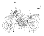
- Fig. 1 is a left side view of a straddle-type vehicle 1 according to the embodiment of the present invention
- Fig. 2 is a right side view of the straddle-type vehicle 1.
- Fig. 3 is a plan view illustrating a meter MP and its periphery
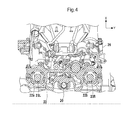
- Fig. 4 is a sectional view taken along a line I-I in Fig. 2 .
- the straddle-type vehicle 1 is an off-road motorcycle, the present invention is applicable to various electric straddle-type vehicles including other types of motorcycles.
- the straddle-type vehicle 1 is sometimes referred to as the vehicle 1.
- the vehicle 1 includes a body frame 10.
- the body frame 10 includes: a head pipe 11 which is provided in a front part of the vehicle; a pair of left and right main frames 12, 12; a down frame 13; and a pair of left and right lower frames 14, 14.
- the head pipe 11 and the down frame 13 are formed of a single member provided to extend along the body center.
- the pair of main frames 12, 12, the down frame 13, and the pair of lower frames 14, 14 are coupled together in a loop fashion, and a power unit 2 is disposed inside an area surrounded by these frames.
- the power unit 2 includes an engine and a transmission.
- An exhaust pipe 6 configured to guide exhaust gas from the engine to an exhaust muffler 5 is provided ahead of the power unit 2.
- the pair of main frames 12, 12 is mounted on an upper part of the head pipe 11, and bends to the left and right above the power unit 2 and then extends obliquely downward and rearward.
- the down frame 13 is mounted on a lower part of the head pipe 11, extends obliquely downward and then downward linearly along the body center at a position ahead of the power unit 2, and is then coupled at its lower end part to a front end part of the pair of left and right lower frames 14, 14.
- Each lower frame 14 bends at a part thereof near a front lower part of the power unit 2 toward a space below the power unit 2 and then extends rearward substantially linearly, and its rear end part is coupled to a lower end part of the corresponding main frame 12.
- a fuel tank 3 supported on the main frames 12, 12 is disposed above the power unit 2.
- a seat 4 is disposed immediately behind the fuel tank 3.
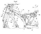
- the seat 4 is supported on a pair of seat frames 15, 15 (see Figs. 8 and 9 ).
- the seat frames 15, 15 extend rearward with their front ends attached to the respective main frames 12, 12.
- a pair of rear frames 16, 16 (see Figs. 8 and 9 ) is connected to the pair of seat frames 15, 15 and the pair of lower frames 14, 14.
- a steering stem 20 is turnably supported on the head pipe 11, and a top bridge 22 is mounted on an upper end part of the steering stem 20.
- a bottom bridge 26 is provided on a lower end part of the steering stem 20.
- the meter MP is coupled to the top bridge 22 via a meter stay 25 and disposed ahead of the top bridge 22.
- the meter MP is a display device configured to display various kinds of information such as vehicle speed and engine speed.
- a pair of left and right front forks 23L, 23R is supported by fork insertion holes 22a, 22b located in left and right end parts of the top bridge 22.
- the pair of front forks 23L, 23R is also supported by the bottom bridge 26.
- the pair of front forks 23L, 23R is sometimes simply referred to as the pair of front forks 23.
- a front wheel FW is rotatably supported by lower end parts of the pair of front forks 23 and designed to be steered by a handlebar 24 mounted on the top bridge 22.
- a pair of grips 21L, 21R to be gripped by a rider is provided on left and right end parts of the handlebar 24.
- a brake lever 30 and a brake master cylinder 31 configured to work in conjunction with the brake lever 30 are provided next to the grip 21R.
- a front end part of a rear swing arm 18 is swingably supported by the main frames 12, 12 via a pivot shaft 17.
- a rear wheel RW is supported by a rear end part of the rear swing arm 18, and the rear wheel RW is driven to rotate by a chain (not illustrated) wound around a drive sprocket (not illustrated) of the power unit 2 and a driven sprocket (not illustrated) of the rear wheel RW.
- the pair of main frames 12 is also provided with a brake pedal 32 and a brake master cylinder 33 configured to work in conjunction with the brake pedal 32.
- a brake system 34 is configured to brake the front wheel FW.
- the brake system 34 includes: a brake disc 34a which is secured coaxially with the front wheel FW; and a brake caliper 34b which is supported by the lower end part of the front fork 23L.
- a speed sensor 37 configured to measure the rotating speed of the front wheel FW is placed at the lower end part of the front fork 23L.
- a brake system 35 is configured to brake the rear wheel RW.
- the brake system 35 includes: a brake disc 35a which is secured coaxially with the rear wheel RW; and a brake caliper 35b which is supported by an end part of the rear swing arm 18.
- the brake master cylinder 31 and the brake caliper 34b are connected to each other via an ABS modulator 36, and the brake caliper 34b works upon manipulation of the brake lever 30.
- the ABS modulator 36 controls brake hydraulic pressure to act on the brake caliper 34b if the front wheel FW is about to be locked, and thereby prevents the front wheel FW from being locked.
- the brake master cylinder 33 and the brake caliper 35b are connected to each other via the ABS modulator 36, and the brake caliper 35b works upon manipulation of the brake pedal 32.
- the ABS modulator 36 controls brake hydraulic pressure to act on the brake caliper 35b if the rear wheel RW is about to be locked, and thereby prevents the rear wheel RW from being locked.
- the ABS modulator 36 is disposed behind the top bridge 22.
- the ABS modulator is supported by the seat frames 15 and the rear frames 16 via a mounting stay 36a, but its installation location is not limited to this.
- the ABS modulator 36 is formed from: a valve unit; a motor which is configured to run the valve unit; and a control circuit which is configured to control the motor.
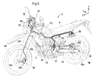
- FIGs. 5 to 7 are perspective views illustrating the layout of the brake piping, in which Fig. 5 is a perspective view, Fig. 6 is a plan view, and Fig. 7 is a front view.
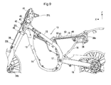
- Figs. 8 and 9 illustrate the layout of the brake piping on the body frame 10, in which Fig. 8 is a perspective view and Fig. 9 is a left side view.
- the brake piping includes: a brake pipe 40 which connects the brake master cylinder 31 and the ABS modulator 36 to each other; a brake pipe 41 which connects the ABS modulator 36 and the brake caliper 34b of the brake system 34; a brake pipe 43 which connects the brake master cylinder 33 and the ABS modulator 36; and a brake pipe 44 which connects the ABS modulator 36 and the brake caliper 35b of the brake system 35.
- Each of the brake pipes 40, 41, 43, and 44 is basically formed of a flexible hose made of rubber, for example, and partially uses a metal pipe and the like.
- the brake pipes 40, 41 related to the brake system 34 are designed to have a relatively long length. The routing of these pipes is described briefly.
- the brake pipe 40 extends from the brake master cylinder 31 to the front side of the head pipe 11, and then extends to the outer side of the left main frame 12 through a space between the head pipe 11 and the front fork 23L and between the top bridge 22 and the bottom bridge 26. This brake pipe further extends to the ABS modulator 36 through a space between the main frames 12, 12.
- the brake pipe 40 extends from the brake master cylinder 31 located on the right side of the vehicle to the ABS modulator 36 while making a detour to the left side of the vehicle and passing through the left side of the vehicle. This reduces the curvature of the brake pipe 40 in bending.
- the brake pipe 41 passes through the left side of the vehicle from the ABS modulator 36, then bends to the right side of the vehicle, and then extends forward of the head pipe 11 while passing through the right side of the vehicle.
- This pipe further extends upward through a supporter 42 secured to the vehicle body, and then curves to the left side of the vehicle body and extends to the brake caliper 34b.
- the ABS modulator 36 is located on the left side of the vehicle, whereas the brake master cylinder 33 and the brake caliper 35b are located on the right side of the vehicle.
- the brake pipe 43 slightly extends to the left side of the vehicle from the brake master cylinder 33, and then extends toward the rear of the vehicle to be connected to the ABS modulator 36.
- the brake pipe 44 extends toward the front of the vehicle from the ABS modulator 36, then slightly extends to the right side of the vehicle, and then extends toward the rear of the vehicle to be connected to the brake caliper 35b.
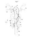
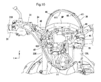
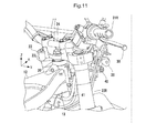
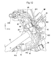
- Figs. 10 to 12 are views illustrating the layout of the brake pipes 40, 41, in which Fig. 10 is a front view, Fig. 11 is a perspective view, and Fig. 12 is a right side view.
- the vehicle 1 of this embodiment is an off-road motorcycle, and thus the pair of front forks 23 is designed to have relatively long expansion stroke.
- the brake pipe 41 needs to have play long enough to follow the expansion of the pair of front forks 23.
- the brake pipe 41 is curved in the shape of an inverted U protruding upward in the front view. By ensuring the pipe length with this curve portion, the brake pipe 41 has such a configuration as to follow the expansion of the pair of front forks 23.
- the brake pipe 41 first extends from a part of the vehicle behind the top bridge 22 and below the top bridge 22 to the front side of the vehicle through a space between the head pipe 11 and the front fork 23R and between the top bridge 22 and the bottom bridge 26, and is then supported by the supporter 42.
- the brake pipe 40 passes through the space at the left side of the head pipe 11, and these brake pipes are configured so that the brake pipe 41 passes through a right one of the spaces partitioned off by the head pipe 11 and the brake pipe 40 passes though the left one. This makes the brake pipes 40, 41 less likely to interfere with each other during steering. Further, since the brake pipes 40, 41 cross each other in a relatively open space located ahead of the head pipe 11, it is possible to prevent the brake pipes 40, 41 from interfering with each other during steering.
- the brake pipe 41 has an anchor point 41a attached to the down frame 13 at a position rearward of the pair of front forks 23 (i.e., at a part of the brake pipe on its rear side with respect to the vehicle that is located before the space between the top bridge 22 and the bottom bridge 26 through which this pipe passes).
- the anchor point 41a is disposed on an upper part of the down frame 13 at a position below the supporter 42 and on the further inner side than the supporter in the vehicle widthwise direction.
- the brake pipe 41 extends rearward and inward as seen from the supporter 42, it becomes easier to prevent the pair of front forks 23 and the brake pipe 41 from coming into contact with each other during steering. In addition, it is possible to minimize the movement of the brake pipe 41 during steering and, at the same time, dispose the brake pipe 41 compactly in the vehicle widthwise direction.
- the brake pipe 41 passes through the space between the top bridge 22 and the bottom bridge 26, and is then supported by the supporter 42.
- the supporter 42 is secured to the vehicle body, and the brake pipe 41 is secured to the vehicle body by the supporter 42.
- the supporter 42 is placed on the front fork 23R side at a position ahead of the top bridge 22 with respect to the vehicle.
- the supporter 42 is disposed so as to overlap the front fork 23R when the vehicle is viewed from the front.
- the brake pipe 41 can be secured at a position spaced from the brake caliper 34b as the connection destination in the vehicle widthwise direction, which enables the inverted U-shaped curve portion of the pipe to have a larger width in the lateral direction. This is advantageous in ensuring the pipe length of the brake pipe 41 long enough to follow the expansion of the pair of front forks 23.
- the brake pipe 41 since the brake pipe 41 has such a shape as to span the front fork 23R and the front fork 23L, the brake pipe 41 can be prevented from interfering with other vehicle constituents arranged between or around the pair of front forks 23.
- the supporter 42 is secured to the meter stay 25.
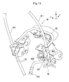
- Fig. 13 is a perspective view of the meter stay 25 and the supporter 42.
- the brake pipe 41 includes: a pipe section 411 which extends from the supporter 42 toward the brake system 34; and a pipe section 412 which extends from the supporter 42 toward the ABS modulator 36.
- Each of the pipe sections 411, 412 is a flexible hose, and the pipe section 411 constitutes the inverted U-shaped portion.
- the supporter 42 includes: a fastening portion 421 which is fastened to the meter stay 25 with a bolt; a front connection portion 422 to which the pipe section 411 is connected; and a rear connection portion 423 to which the pipe section 412 is connected.
- the fastening portion 421 employs a banjo fitting structure using a banjo bolt, for example.
- the front connection portion 422 and the rear connection portion 423 are metal pipes communicating with each other and being directed in different directions. Specifically, the front connection portion 422 is directed upward from the fastening portion 421 and serves as a guide for the pipe section 411 to extend upward. Meanwhile, the rear connection portion 423 is directed rearward and inward and serves as a guide for the pipe section 412 to extend to the anchor point 41a.
- the brake pipe 41 can be stably secured in a small space.
- the brake pipe 41 extending from the rear can be disposed at an upper position as desired.
- the pipe section 411 of the brake pipe 41 extends upward from the front connection portion 422, and curves in the shape of an inverted U toward the front fork 23L while passing through a higher position than the top bridge 22.
- the brake pipe then extends downward along the front fork 23L.
- Multiple ring-shaped holders 45 are provided on the front fork 23L side, and the brake pipe 41 passes through the multiple holders 45.
- the holders 45 do not restrain the movement of the brake pipe 41 in its longitudinal direction. Accordingly, the level of the inverted U-shaped portion of the pipe section 411 of the brake pipe 41 varies with the expansion of the pair of front forks 23, whereby the pipe section 411 can follow this expansion.
- a sensor cable 38 connected to the speed sensor 37 is fixed to the brake pipe 41 with multiple fixing tools 46.
- the sensor cable 38 connects the speed sensor 37 and the ABS modulator 36 to each other, for example.
- the sensor cable 38 may connect the speed sensor 37 and the meter MP to each other instead.
- the sensor cable 38 curves in the shape of an inverted U from the front fork 23R side toward the front fork 23L while passing through a higher position than the top bridge 22. With this curve, the sensor cable 38 can also ensure play long enough to follow the expansion of the pair of front forks 23.
- the brake pipe 41 can also be used as a support member for the sensor cable 38. Some of the multiple fixing tools 46 fix the sensor cable 38 to the pipe section 411 of the brake pipe 41 at positions higher than the top bridge 22, which makes the pipe section 411 and the sensor cable 38 less likely to be separated from each other during the expansion of the pair of front forks 23.
- the pipe section 411 of the brake pipe 41 and the sensor cable 38 pass through the multiple fixing tools 46 and extend downward along the front fork 23L.
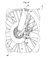
- the pipe section 411 and the sensor cable 38 are separated at their end parts from each other in the longitudinal direction of the vehicle, and the pipe section 411 is connected to the brake caliper 34b as illustrated in Fig. 14 whereas the sensor cable 38 is connected to the speed sensor 37 as illustrated in Fig. 15 .
- the brake pipe 41 since the brake pipe 41 is placed to pass through a space above the top bridge 22, the brake pipe 41 can ensure play long enough to follow the expansion of the pair of front forks 23 even if this expansion is large.
- the brake pipe 41 extending from the ABS modulator 36 disposed at the rear passes through the space between the front fork 23R and the head pipe 11, it is possible to inhibit the brake pipe 41 from protruding outside the pair of front forks 23 and dispose the brake pipe 41 compactly.
- the brake pipe 41 is supported by the supporter 42 at a position ahead of the top bridge 22, the swing of the brake pipe 41 caused by the expansion of the pair of front forks 23 becomes relatively smaller at a position between the front fork 23R and the head pipe 11, whereby the brake pipe 41 can be disposed in the narrow space between the front fork 23R and the head pipe 11.
- the ABS modulator 36 behind the top bridge 22 and, at the same time, allow the brake pipe 41 to ensure play long enough to follow the expansion of the pair of front forks 23.
Landscapes
- Engineering & Computer Science (AREA)
- Mechanical Engineering (AREA)
- Physics & Mathematics (AREA)
- Electromagnetism (AREA)
- Fluid Mechanics (AREA)
- Transportation (AREA)
- Motorcycle And Bicycle Frame (AREA)
- Regulating Braking Force (AREA)
- Valves And Accessory Devices For Braking Systems (AREA)
Description
- The present invention relates to a straddle-type vehicle, and particularly relates to a straddle-type vehicle equipped with Antilock Braking System (ABS).
- Straddle-type vehicles employing ABS as their braking devices have been proposed (
Patent Documents - Meanwhile, in straddle-type vehicles represented by off-road vehicles, since the amount of stroke of a pair of front forks is set relatively long, the brake pipe connected to the brake system of the front wheel needs to be placed so that it can follow the expansion of the pair of front forks.
Patent Document 2 discloses a structure in which an ABS modulator (ABS module) is disposed on a handlebar and a brake pipe extending from the ABS modulator to a brake system of a front wheel is curved above a top bridge. This curve of the brake pipe above the top bridge allows the brake pipe to ensure play long enough to follow the expansion of a pair of front forks. -
-
Patent Document 1 Japanese Patent Application Publication No.2010-58699 -
Patent Document 2 Japanese Patent Application Publication No.2012-210891 - Since meters and the like are arranged around a handlebar, it is sometimes difficult to ensure an installation space for an ABS modulator. If the ABS modulator is disposed behind a top bridge, the layout of a brake pipe for connecting the ABS modulator and a brake system of a front wheel to each other becomes an issue. Specifically, to curve the brake pipe extending from the ABS modulator at a position above the top bridge as in
Patent Document 2, the brake pipe needs to be placed while keeping away from the top bridge, meter wiring, and the like. This may complicate the layout of the brake pipe and make installation of the brake pipe harder, or hinder a compact configuration around the top bridge. - An objective of the present invention is to dispose an ABS modulator behind a top bridge and, at the same time, allow a brake pipe to ensure play long enough to follow the expansion of a pair of front forks.
- The present invention as recited in
claim 1 provides
a straddle-type vehicle (1) including: - a steering stem (20) which is turnably supported on a head pipe (11) provided in a front part of the vehicle;
- a top bridge (22) which is provided on an upper end part of the steering stem (20);
- a pair of front forks (23L, 23R) which are respectively supported by left and right fork insertion holes (22a, 22b) of the top bridge (22);
- a front wheel braking unit (34) which is placed on a side close to a first front fork (23L) of the pair of front forks (23L, 23R) and configured to apply braking force to a front wheel (FW);
- an ABS modulator (36) which is disposed behind the top bridge (22) and configured to control the braking force of the front wheel braking unit (34); and
- a brake pipe (41) which connects the ABS modulator (36) and the front wheel braking unit (34) to each other, characterized in that
- the straddle-type vehicle includes a supporter (42) which is placed on a side close to a second front fork (23R) of the pair of front forks (23L, 23R) at a position ahead of the top bridge (22) with respect to the vehicle and configured to support the brake pipe (41), and
- the brake pipe (41)
- extends from a part of the vehicle behind the top bridge (22) and passes through a space between the head pipe (11) and the second front fork (23R) below the top bridge (22) to be supported by the supporter (42),
- extends upward through the supporter (42) and curves toward the first front fork (23L) while passing through a higher position than the top bridge (22), and
- extends along the first front fork (23L) to be connected to the front wheel braking unit (34).
- The present invention as recited in
claim 2 is characterized in that
the brake pipe (41) extends through the supporter (42) toward a rear of the vehicle so as to pass through a inner side than the supporter (42) in a vehicle widthwise direction,
the head pipe (11) includes a down frame (13) which extends downward from the head pipe (11),
the brake pipe (41) has an anchor point (41a) which is attached to the down frame (13) at a position behind the pair of front forks (23L, 23R), and
the anchor point (41a) is disposed on an upper part of the down frame (13) at a position below the supporter (42) and on the inner side than the supporter in the vehicle widthwise direction. - The present invention as recited in
claim 3 is characterized in that the supporter (42) is disposed to overlap the second front fork (23R) when the vehicle is seen from a front. - The present invention as recited in claim 4 is characterized in that the vehicle further includes:
- a meter (MP) which is disposed ahead of the top bridge (22); and
- a meter stay (25) which couples the meter (MP) and the top bridge (22) to each other, and
- the supporter (42) is secured to the meter stay (25).
- The present invention as recited in
claim 5 is characterized in that
the brake pipe (41) includes: - a first pipe section (411) which extends from the supporter (42) toward the front wheel braking unit (34); and
- a second pipe section (412) which extends from the supporter (42) toward the ABS modulator (36),
- a fastening portion (421) which is fastened to the meter stay (25);
- a front connection portion (422) to which the first pipe section (411) is connected; and
- a rear connection portion (423) to which the second pipe section (412) is connected, and
- The present invention as recited in
claim 6 is characterized in that the vehicle further includes: - a speed sensor (37) which is placed on the side close to the first front fork (23L) and configured to measure rotating speed of the front wheel; and
- a sensor cable (38) which is connected to the speed sensor (37), and
- the sensor cable (38)
- curves from the side close to the second front fork (23R) toward the first front fork (23L) while passing through a higher position than the top bridge (22), and
- extends along the first front fork (23L) to be connected to the speed sensor (37).
- The present invention as recited in claim 7 is characterized in that the sensor cable (38) is fixed to the brake pipe (41) at a higher position than the top bridge (22).
- The present invention as recited in claim 8 is characterized in that the vehicle further includes:
- a handlebar (24) which is supported on the steering stem (20);
- a brake master cylinder (31) which is provided on the handlebar (24); and
- a second brake pipe (40) which connects the brake master cylinder (31) and the ABS modulator (36) to each other, and
- the second brake pipe (40) extends to a front side of the head pipe (11) from the brake master cylinder (31), and extends rearward while passing through a space between the head pipe (11) and the first front fork (23L).
- According to the present invention as recited in
claim 1, since the brake pipe is placed to pass through a space above the top bridge, the brake pipe can ensure play long enough to follow the expansion of the pair of front forks even if this expansion is large in the vehicle. In addition, since the brake pipe extending from the ABS modulator disposed at the rear passes through the space between the second front fork and the head pipe, it is possible to inhibit the brake pipe from protruding outside the pair of front forks and dispose the brake pipe compactly. Further, since the brake pipe is supported by the supporter at a position ahead of the top bridge, the swing of the brake pipe caused by the expansion of the pair of front forks becomes relatively smaller at a position between the second front fork and the head pipe, whereby the brake pipe can be disposed in the narrow space between the second front fork and the head pipe. Thus, it is possible to dispose the ABS modulator behind the top bridge and, at the same time, allow the brake pipe to ensure play long enough to follow the expansion of the pair of front forks. - According to the present invention as recited in
claim 2, since the brake pipe extends rearward and inward from the supporter owing to the position of the anchor point, it becomes easier to prevent the pair of front forks and the brake pipe from coming into contact with each other during steering. In addition, since the anchor point is disposed on the upper part of the down frame, the anchor point can be located near the head pipe, thus making it possible to minimize the movement of the brake pipe during steering and, at the same time, dispose the brake pipe compactly in the vehicle widthwise direction. - According to the present invention as recited in
claim 3, since the brake pipe has such a shape as to span the second front fork and the first front fork, the brake pipe can be prevented from interfering with other vehicle constituents arranged between or around the pair of front forks. - According to the present invention as recited in claim 4, by securing the supporter to the meter stay, it is possible to secure the brake pipe easily without additionally disposing any member to the top bridge or the head pipe for supporting the supporter.
- According to the present invention as recited in
claim 5, since the pipe sections of the brake pipe can be secured at different angles by the supporter, the brake pipe can be stably secured in a small space. In addition, the brake pipe extending from the rear can be disposed at an upper position as desired. - According to the present invention as recited in
claim 6, the sensor cable can also ensure the length long enough to follow the expansion of the pair of front forks. - According to the present invention as recited in claim 7, the brake pipe can also be used as a support member for the sensor cable.
- According to the present invention as recited in claim 8, it is possible to reduce the bend of the second brake pipe and, at the same time, allow the brake pipe connected to the front wheel braking unit to ensure enough space for swinging without any interference by the second brake pipe.
-
-
Fig. 1 is a left side view of a straddle-type vehicle according to an embodiment of the present invention. -
Fig. 2 is a right side view of the straddle-type vehicle ofFig. 1 . -
Fig. 3 is a plan view illustrating a meter and its periphery of the straddle-type vehicle ofFig. 1 . -
Fig. 4 is a sectional view taken along a line I-I inFig. 2 . -
Fig. 5 is a perspective view illustrating the layout of brake piping of the straddle-type vehicle ofFig. 1 . -
Fig. 6 is a plan view illustrating the layout of the brake piping of the straddle-type vehicle ofFig. 1 . -
Fig. 7 is a front view illustrating the layout of the brake piping of the straddle-type vehicle ofFig. 1 . -
Fig. 8 is a perspective view illustrating the layout of the brake piping on a frame of the straddle-type vehicle ofFig. 1 . -
Fig. 9 is a left side view illustrating the layout of the brake piping on the frame of the straddle-type vehicle ofFig. 1 . -
Fig. 10 is a front view illustrating the layout of the brake piping of the straddle-type vehicle ofFig. 1 . -
Fig. 11 is a perspective view illustrating the layout of the brake piping of the straddle-type vehicle ofFig. 1 . -
Fig. 12 is a right side view illustrating the layout of the brake piping of the straddle-type vehicle ofFig. 1 . -
Fig. 13 is a perspective view illustrating a meter stay and a supporter of the straddle-type vehicle ofFig. 1 . -
Fig. 14 is a perspective view illustrating a front wheel brake system of the straddle-type vehicle ofFig. 1 . -
Fig. 15 is a perspective view illustrating a front wheel speed sensor of the straddle-type vehicle ofFig. 1 . - A straddle-type vehicle according to an embodiment of the present invention is described with reference to the drawings. Throughout the drawings, arrows X, Y, and Z indicate directions orthogonal to one another, in which the X direction indicates the longitudinal direction of the straddle-type vehicle, the Y direction indicates the vehicle widthwise direction (lateral direction) of the straddle-type vehicle, and the Z direction indicates the vertical direction thereof.
-
Fig. 1 is a left side view of a straddle-type vehicle 1 according to the embodiment of the present invention, andFig. 2 is a right side view of the straddle-type vehicle 1.Fig. 3 is a plan view illustrating a meter MP and its periphery, andFig. 4 is a sectional view taken along a line I-I inFig. 2 . Although the straddle-type vehicle 1 is an off-road motorcycle, the present invention is applicable to various electric straddle-type vehicles including other types of motorcycles. Hereinbelow, the straddle-type vehicle 1 is sometimes referred to as thevehicle 1. - The
vehicle 1 includes abody frame 10. Thebody frame 10 includes: ahead pipe 11 which is provided in a front part of the vehicle; a pair of left and rightmain frames down frame 13; and a pair of left and rightlower frames head pipe 11 and thedown frame 13 are formed of a single member provided to extend along the body center. - The pair of
main frames down frame 13, and the pair oflower frames power unit 2 is disposed inside an area surrounded by these frames. Thepower unit 2 includes an engine and a transmission. Anexhaust pipe 6 configured to guide exhaust gas from the engine to anexhaust muffler 5 is provided ahead of thepower unit 2. - The pair of
main frames head pipe 11, and bends to the left and right above thepower unit 2 and then extends obliquely downward and rearward. The downframe 13 is mounted on a lower part of thehead pipe 11, extends obliquely downward and then downward linearly along the body center at a position ahead of thepower unit 2, and is then coupled at its lower end part to a front end part of the pair of left and rightlower frames lower frame 14 bends at a part thereof near a front lower part of thepower unit 2 toward a space below thepower unit 2 and then extends rearward substantially linearly, and its rear end part is coupled to a lower end part of the correspondingmain frame 12. - A
fuel tank 3 supported on themain frames power unit 2. A seat 4 is disposed immediately behind thefuel tank 3. The seat 4 is supported on a pair of seat frames 15, 15 (seeFigs. 8 and9 ). The seat frames 15, 15 extend rearward with their front ends attached to the respectivemain frames rear frames 16, 16 (seeFigs. 8 and9 ) is connected to the pair of seat frames 15, 15 and the pair oflower frames - A steering
stem 20 is turnably supported on thehead pipe 11, and atop bridge 22 is mounted on an upper end part of thesteering stem 20. Abottom bridge 26 is provided on a lower end part of thesteering stem 20. The meter MP is coupled to thetop bridge 22 via ameter stay 25 and disposed ahead of thetop bridge 22. The meter MP is a display device configured to display various kinds of information such as vehicle speed and engine speed. - A pair of left and right
front forks fork insertion holes top bridge 22. The pair offront forks bottom bridge 26. - The pair of
front forks handlebar 24 mounted on thetop bridge 22. A pair ofgrips handlebar 24. In addition, abrake lever 30 and abrake master cylinder 31 configured to work in conjunction with thebrake lever 30 are provided next to thegrip 21R. - A front end part of a
rear swing arm 18 is swingably supported by themain frames pivot shaft 17. A rear wheel RW is supported by a rear end part of therear swing arm 18, and the rear wheel RW is driven to rotate by a chain (not illustrated) wound around a drive sprocket (not illustrated) of thepower unit 2 and a driven sprocket (not illustrated) of the rear wheel RW. - The pair of
main frames 12 is also provided with abrake pedal 32 and abrake master cylinder 33 configured to work in conjunction with thebrake pedal 32. - A
brake system 34 is configured to brake the front wheel FW. Thebrake system 34 includes: abrake disc 34a which is secured coaxially with the front wheel FW; and abrake caliper 34b which is supported by the lower end part of thefront fork 23L. In addition, aspeed sensor 37 configured to measure the rotating speed of the front wheel FW is placed at the lower end part of thefront fork 23L. Abrake system 35 is configured to brake the rear wheel RW. Thebrake system 35 includes: abrake disc 35a which is secured coaxially with the rear wheel RW; and abrake caliper 35b which is supported by an end part of therear swing arm 18. - The
brake master cylinder 31 and thebrake caliper 34b are connected to each other via anABS modulator 36, and thebrake caliper 34b works upon manipulation of thebrake lever 30. Based on the result of measurement performed by thespeed sensor 37, theABS modulator 36 controls brake hydraulic pressure to act on thebrake caliper 34b if the front wheel FW is about to be locked, and thereby prevents the front wheel FW from being locked. Likewise, thebrake master cylinder 33 and thebrake caliper 35b are connected to each other via theABS modulator 36, and thebrake caliper 35b works upon manipulation of thebrake pedal 32. Based on the result of measurement performed by a sensor (not illustrated) configured to detect the rotating speed of the rear wheel RW, theABS modulator 36 controls brake hydraulic pressure to act on thebrake caliper 35b if the rear wheel RW is about to be locked, and thereby prevents the rear wheel RW from being locked. - The
ABS modulator 36 is disposed behind thetop bridge 22. In the case of this embodiment, the ABS modulator is supported by the seat frames 15 and the rear frames 16 via a mountingstay 36a, but its installation location is not limited to this. By employing the configuration in which theABS modulator 36 is not disposed around a steering system by disposing theABS modulator 36 behind thetop bridge 22, it becomes easier to use a space around the steering system as an installation space for other constituents (e.g., an installation space for the meter MP). - For example, the
ABS modulator 36 is formed from: a valve unit; a motor which is configured to run the valve unit; and a control circuit which is configured to control the motor. - A description is given of the layout of brake piping related to the
brake systems ABS modulator 36.Figs. 5 to 7 are perspective views illustrating the layout of the brake piping, in whichFig. 5 is a perspective view,Fig. 6 is a plan view, andFig. 7 is a front view. In addition,Figs. 8 and9 illustrate the layout of the brake piping on thebody frame 10, in whichFig. 8 is a perspective view andFig. 9 is a left side view. - The brake piping includes: a
brake pipe 40 which connects thebrake master cylinder 31 and theABS modulator 36 to each other; abrake pipe 41 which connects theABS modulator 36 and thebrake caliper 34b of thebrake system 34; abrake pipe 43 which connects thebrake master cylinder 33 and theABS modulator 36; and abrake pipe 44 which connects theABS modulator 36 and thebrake caliper 35b of thebrake system 35. Each of thebrake pipes - In the case of this embodiment, since the
ABS modulator 36 is located in a rear part of the vehicle, thebrake pipes brake system 34 are designed to have a relatively long length. The routing of these pipes is described briefly. Thebrake pipe 40 extends from thebrake master cylinder 31 to the front side of thehead pipe 11, and then extends to the outer side of the leftmain frame 12 through a space between thehead pipe 11 and thefront fork 23L and between thetop bridge 22 and thebottom bridge 26. This brake pipe further extends to theABS modulator 36 through a space between themain frames brake pipe 40 extends from thebrake master cylinder 31 located on the right side of the vehicle to theABS modulator 36 while making a detour to the left side of the vehicle and passing through the left side of the vehicle. This reduces the curvature of thebrake pipe 40 in bending. - Meanwhile, the
brake pipe 41 passes through the left side of the vehicle from theABS modulator 36, then bends to the right side of the vehicle, and then extends forward of thehead pipe 11 while passing through the right side of the vehicle. This pipe further extends upward through asupporter 42 secured to the vehicle body, and then curves to the left side of the vehicle body and extends to thebrake caliper 34b. - In the case of this embodiment, the
ABS modulator 36 is located on the left side of the vehicle, whereas thebrake master cylinder 33 and thebrake caliper 35b are located on the right side of the vehicle. Thebrake pipe 43 slightly extends to the left side of the vehicle from thebrake master cylinder 33, and then extends toward the rear of the vehicle to be connected to theABS modulator 36. Thebrake pipe 44 extends toward the front of the vehicle from theABS modulator 36, then slightly extends to the right side of the vehicle, and then extends toward the rear of the vehicle to be connected to thebrake caliper 35b. - The layout of the
brake pipes Figs. 10 to 12 are views illustrating the layout of thebrake pipes Fig. 10 is a front view,Fig. 11 is a perspective view, andFig. 12 is a right side view. As described previously, thevehicle 1 of this embodiment is an off-road motorcycle, and thus the pair of front forks 23 is designed to have relatively long expansion stroke. Thebrake pipe 41 needs to have play long enough to follow the expansion of the pair of front forks 23. - In the case of this embodiment, as is clear from
Fig. 10 , thebrake pipe 41 is curved in the shape of an inverted U protruding upward in the front view. By ensuring the pipe length with this curve portion, thebrake pipe 41 has such a configuration as to follow the expansion of the pair of front forks 23. - The layout of the
brake pipe 41 is described more specifically. As illustrated inFig. 11 , thebrake pipe 41 first extends from a part of the vehicle behind thetop bridge 22 and below thetop bridge 22 to the front side of the vehicle through a space between thehead pipe 11 and thefront fork 23R and between thetop bridge 22 and thebottom bridge 26, and is then supported by thesupporter 42. As described previously, thebrake pipe 40 passes through the space at the left side of thehead pipe 11, and these brake pipes are configured so that thebrake pipe 41 passes through a right one of the spaces partitioned off by thehead pipe 11 and thebrake pipe 40 passes though the left one. This makes thebrake pipes brake pipes head pipe 11, it is possible to prevent thebrake pipes - The configuration related to the steering performance is further described. As illustrated in
Fig. 12 , thebrake pipe 41 has ananchor point 41a attached to thedown frame 13 at a position rearward of the pair of front forks 23 (i.e., at a part of the brake pipe on its rear side with respect to the vehicle that is located before the space between thetop bridge 22 and thebottom bridge 26 through which this pipe passes). Theanchor point 41a is disposed on an upper part of thedown frame 13 at a position below thesupporter 42 and on the further inner side than the supporter in the vehicle widthwise direction. By securing thebrake pipe 41 with theanchor point 41a set at this position, thebrake pipe 41 is secured near thehead pipe 11 and close to the center in the vehicle widthwise direction. Since thebrake pipe 41 extends rearward and inward as seen from thesupporter 42, it becomes easier to prevent the pair of front forks 23 and thebrake pipe 41 from coming into contact with each other during steering. In addition, it is possible to minimize the movement of thebrake pipe 41 during steering and, at the same time, dispose thebrake pipe 41 compactly in the vehicle widthwise direction. - Next, the
brake pipe 41 passes through the space between thetop bridge 22 and thebottom bridge 26, and is then supported by thesupporter 42. Thesupporter 42 is secured to the vehicle body, and thebrake pipe 41 is secured to the vehicle body by thesupporter 42. Thesupporter 42 is placed on thefront fork 23R side at a position ahead of thetop bridge 22 with respect to the vehicle. In the case of this embodiment, in particular, as illustrated inFig. 10 , thesupporter 42 is disposed so as to overlap thefront fork 23R when the vehicle is viewed from the front. Accordingly, thebrake pipe 41 can be secured at a position spaced from thebrake caliper 34b as the connection destination in the vehicle widthwise direction, which enables the inverted U-shaped curve portion of the pipe to have a larger width in the lateral direction. This is advantageous in ensuring the pipe length of thebrake pipe 41 long enough to follow the expansion of the pair of front forks 23. In addition, since thebrake pipe 41 has such a shape as to span thefront fork 23R and thefront fork 23L, thebrake pipe 41 can be prevented from interfering with other vehicle constituents arranged between or around the pair of front forks 23. - In the case of this embodiment, the
supporter 42 is secured to themeter stay 25.Fig. 13 is a perspective view of themeter stay 25 and thesupporter 42. By securing thesupporter 42 to the vehicle body by use of themeter stay 25, it is possible to secure thebrake pipe 41 easily without additionally disposing any member to thetop bridge 22 or thehead pipe 11 for supporting thesupporter 42. - The
brake pipe 41 includes: apipe section 411 which extends from thesupporter 42 toward thebrake system 34; and apipe section 412 which extends from thesupporter 42 toward theABS modulator 36. Each of thepipe sections pipe section 411 constitutes the inverted U-shaped portion. - The
supporter 42 includes: afastening portion 421 which is fastened to themeter stay 25 with a bolt; afront connection portion 422 to which thepipe section 411 is connected; and arear connection portion 423 to which thepipe section 412 is connected. Thefastening portion 421 employs a banjo fitting structure using a banjo bolt, for example. Thefront connection portion 422 and therear connection portion 423 are metal pipes communicating with each other and being directed in different directions. Specifically, thefront connection portion 422 is directed upward from thefastening portion 421 and serves as a guide for thepipe section 411 to extend upward. Meanwhile, therear connection portion 423 is directed rearward and inward and serves as a guide for thepipe section 412 to extend to theanchor point 41a. In this way, since thepipe sections brake pipe 41 can be secured at different angles by thesupporter 42, thebrake pipe 41 can be stably secured in a small space. In addition, thebrake pipe 41 extending from the rear can be disposed at an upper position as desired. - Referring to
Fig. 10 , thepipe section 411 of thebrake pipe 41 extends upward from thefront connection portion 422, and curves in the shape of an inverted U toward thefront fork 23L while passing through a higher position than thetop bridge 22. The brake pipe then extends downward along thefront fork 23L. Multiple ring-shapedholders 45 are provided on thefront fork 23L side, and thebrake pipe 41 passes through themultiple holders 45. Theholders 45 do not restrain the movement of thebrake pipe 41 in its longitudinal direction. Accordingly, the level of the inverted U-shaped portion of thepipe section 411 of thebrake pipe 41 varies with the expansion of the pair of front forks 23, whereby thepipe section 411 can follow this expansion. - A
sensor cable 38 connected to thespeed sensor 37 is fixed to thebrake pipe 41 withmultiple fixing tools 46. Thesensor cable 38 connects thespeed sensor 37 and theABS modulator 36 to each other, for example. Thesensor cable 38 may connect thespeed sensor 37 and the meter MP to each other instead. - As in the case of the
brake pipe 41, thesensor cable 38 curves in the shape of an inverted U from thefront fork 23R side toward thefront fork 23L while passing through a higher position than thetop bridge 22. With this curve, thesensor cable 38 can also ensure play long enough to follow the expansion of the pair of front forks 23. In addition, by fixing thesensor cable 38 to thebrake pipe 41 with themultiple fixing tools 46, thebrake pipe 41 can also be used as a support member for thesensor cable 38. Some of themultiple fixing tools 46 fix thesensor cable 38 to thepipe section 411 of thebrake pipe 41 at positions higher than thetop bridge 22, which makes thepipe section 411 and thesensor cable 38 less likely to be separated from each other during the expansion of the pair of front forks 23. - While being bundled together, the
pipe section 411 of thebrake pipe 41 and thesensor cable 38 pass through themultiple fixing tools 46 and extend downward along thefront fork 23L. Thepipe section 411 and thesensor cable 38 are separated at their end parts from each other in the longitudinal direction of the vehicle, and thepipe section 411 is connected to thebrake caliper 34b as illustrated inFig. 14 whereas thesensor cable 38 is connected to thespeed sensor 37 as illustrated inFig. 15 . - As has been described, in this embodiment, since the
brake pipe 41 is placed to pass through a space above thetop bridge 22, thebrake pipe 41 can ensure play long enough to follow the expansion of the pair of front forks 23 even if this expansion is large. In addition, since thebrake pipe 41 extending from theABS modulator 36 disposed at the rear passes through the space between thefront fork 23R and thehead pipe 11, it is possible to inhibit thebrake pipe 41 from protruding outside the pair of front forks 23 and dispose thebrake pipe 41 compactly. Further, since thebrake pipe 41 is supported by thesupporter 42 at a position ahead of thetop bridge 22, the swing of thebrake pipe 41 caused by the expansion of the pair of front forks 23 becomes relatively smaller at a position between thefront fork 23R and thehead pipe 11, whereby thebrake pipe 41 can be disposed in the narrow space between thefront fork 23R and thehead pipe 11. Thus, it is possible to dispose theABS modulator 36 behind thetop bridge 22 and, at the same time, allow thebrake pipe 41 to ensure play long enough to follow the expansion of the pair of front forks 23. -
- 1
- STRADDLE-TYPE VEHICLE
- 11
- HEAD PIPE
- 20
- STEERING STEM
- 22
- TOP BRIDGE
- 23L
- FRONT FORK
- 23R
- FRONT FORK
- 34
- BRAKE SYSTEM
- 36
- ABS MODULATOR
- 41
- BRAKE PIPE
- 42
- SUPPORTER
Claims (8)
- A straddle-type vehicle (1) including:a steering stem (20) which is turnably supported on a head pipe (11) provided in a front part of said vehicle;a top bridge (22) which is provided on an upper end part of said steering stem (20);a pair of front forks (23L, 23R) which are respectively supported by left and right fork insertion holes (22a, 22b) of said top bridge (22);a front wheel braking unit (34) which is placed on a side close to a first front fork (23L) of said pair of front forks (23L, 23R) and configured to apply braking force to a front wheel (FW);an ABS modulator (36) which is disposed behind said top bridge (22) and configured to control the braking force of said front wheel braking unit (34); anda brake pipe (41) which connects said ABS modulator (36) and said front wheel braking unit (34) to each other,said straddle-type vehicle comprising a supporter (42) which is placed on a side close to a second front fork (23R) of said pair of front forks (23L, 23R) at a position ahead of said top bridge (22) with respect to said vehicle and configured to support said brake pipe (41),wherein said brake pipe (41)extends from a part of said vehicle behind said top bridge (22) and passes through a space between said head pipe (11) and said second front fork (23R) below said top bridge (22) to be supported by said supporter (42),extends upward through said supporter (42) and curves toward said first front fork (23L) while passing through a higher position than said top bridge (22), andextends along said first front fork (23L) to be connected to said front wheel braking unit (34).
- The straddle-type vehicle according to claim 1, wherein
said brake pipe (41) extends through said supporter (42) toward a rear of said vehicle so as to pass through a inner side than said supporter (42) in a vehicle widthwise direction,
said head pipe (11) includes a down frame (13) which extends downward from said head pipe (11),
said brake pipe (41) has an anchor point (41a) which is attached to said down frame (13) at a position behind said pair of front forks (23L, 23R), and
said anchor point (41a) is disposed on an upper part of said down frame (13) at a position below said supporter (42) and on the inner side than said supporter in the vehicle widthwise direction. - The straddle-type vehicle according to claim 1 or 2, wherein
said supporter (42) is disposed to overlap said second front fork (23R) when said vehicle is seen from a front. - The straddle-type vehicle according to any one of claims 1 to 3, further comprising:a meter (MP) which is disposed ahead of said top bridge (22); anda meter stay (25) which couples said meter (MP) and said top bridge (22) to each other,wherein said supporter (42) is secured to said meter stay (25).
- The straddle-type vehicle according to claim 4, wherein
said brake pipe (41) includes:a first pipe section (411) which extends from said supporter (42) toward said front wheel braking unit (34); anda second pipe section (412) which extends from said supporter (42) toward said ABS modulator (36),said supporter (42) includes:a fastening portion (421) which is fastened to said meter stay (25);a front connection portion (422) to which said first pipe section (411) is connected; anda rear connection portion (423) to which said second pipe section (412) is connected, andsaid front connection portion (422) and said rear connection portion (423) are directed in different directions and communicate with each other. - The straddle-type vehicle according to any one of claims 1 to 5, further comprising:a speed sensor (37) which is placed on the side close to said first front fork (23L) and configured to measure rotating speed of said front wheel; anda sensor cable (38) which is connected to said speed sensor (37),wherein said sensor cable (38)curves from the side close to said second front fork (23R) toward said first front fork (23L) while passing through a higher position than said top bridge (22), andextends along said first front fork (23L) to be connected to said speed sensor (37).
- The straddle-type vehicle according to claim 6, wherein said sensor cable (38) is fixed to said brake pipe (41) at a higher position than said top bridge (22).
- The straddle-type vehicle according to any one of claims 1 to 7, further comprising:a handlebar (24) which is supported on said steering stem (20);a brake master cylinder (31) which is provided on said handlebar (24); anda second brake pipe (40) which connects said brake master cylinder (31) and said ABS modulator (36) to each other,wherein said second brake pipe (40) extends to a front side of said head pipe (11) from said brake master cylinder (31), and extends rearward while passing through a space between said head pipe (11) and said first front fork (23L).
Applications Claiming Priority (1)
| Application Number | Priority Date | Filing Date | Title |
|---|---|---|---|
| JP2015149800A JP6220366B2 (en) | 2015-07-29 | 2015-07-29 | Saddle riding vehicle |
Publications (2)
| Publication Number | Publication Date |
|---|---|
| EP3124343A1 true EP3124343A1 (en) | 2017-02-01 |
| EP3124343B1 EP3124343B1 (en) | 2018-03-14 |
Family
ID=56555245
Family Applications (1)
| Application Number | Title | Priority Date | Filing Date |
|---|---|---|---|
| EP16181534.5A Active EP3124343B1 (en) | 2015-07-29 | 2016-07-27 | Straddle-type vehicle |
Country Status (4)
| Country | Link |
|---|---|
| US (1) | US10093385B2 (en) |
| EP (1) | EP3124343B1 (en) |
| JP (1) | JP6220366B2 (en) |
| AU (1) | AU2016204230B2 (en) |
Cited By (5)
| Publication number | Priority date | Publication date | Assignee | Title |
|---|---|---|---|---|
| CN108502079A (en) * | 2017-02-28 | 2018-09-07 | 雅马哈发动机株式会社 | Straddle-type vehicle |
| CN109018139A (en) * | 2017-06-12 | 2018-12-18 | 铃木株式会社 | The body structure of motorcycle |
| CN109720328A (en) * | 2017-10-31 | 2019-05-07 | 本田技研工业株式会社 | Straddle-type vehicle |
| EP3480098A1 (en) * | 2017-11-07 | 2019-05-08 | Yamaha Hatsudoki Kabushiki Kaisha | Straddled vehicle |
| CN111148691A (en) * | 2017-09-28 | 2020-05-12 | 本田技研工业株式会社 | Brake piping structure of saddle-riding vehicle |
Families Citing this family (6)
| Publication number | Priority date | Publication date | Assignee | Title |
|---|---|---|---|---|
| JP2018140761A (en) * | 2017-02-28 | 2018-09-13 | ヤマハ発動機株式会社 | Saddle-riding type vehicle |
| JP7061670B2 (en) * | 2018-08-09 | 2022-04-28 | 本田技研工業株式会社 | Saddle-type vehicle |
| IT201900014109A1 (en) | 2019-08-06 | 2021-02-06 | Yamaha Motor Co Ltd | BRACKET FOR A RIDER-TYPE VEHICLE AND METHOD OF PLACING A CABLE ON A BRACKET FOR A RIDER-TYPE VEHICLE |
| JP7142657B2 (en) | 2020-02-03 | 2022-09-27 | 本田技研工業株式会社 | saddle-riding vehicle |
| JP2022167396A (en) | 2021-04-23 | 2022-11-04 | ヤマハ発動機株式会社 | Saddle riding vehicle |
| JP7730879B2 (en) * | 2023-12-07 | 2025-08-28 | 本田技研工業株式会社 | Saddle-type vehicle |
Citations (5)
| Publication number | Priority date | Publication date | Assignee | Title |
|---|---|---|---|---|
| JP2007076555A (en) * | 2005-09-15 | 2007-03-29 | Kawasaki Heavy Ind Ltd | Motorcycle |
| JP2010052526A (en) * | 2008-08-27 | 2010-03-11 | Kawasaki Heavy Ind Ltd | Brake piping structure of motorcycle, and motorcycle |
| JP2010058699A (en) | 2008-09-04 | 2010-03-18 | Kawasaki Heavy Ind Ltd | Brake piping structure of motorcycle |
| JP2012210891A (en) | 2011-03-31 | 2012-11-01 | Honda Motor Co Ltd | Motorcycle |
| EP2604498A1 (en) * | 2011-12-16 | 2013-06-19 | Suzuki Motor Corporation | Motorcycle brake pipe structure |
Family Cites Families (6)
| Publication number | Priority date | Publication date | Assignee | Title |
|---|---|---|---|---|
| JP4306442B2 (en) | 2003-12-19 | 2009-08-05 | スズキ株式会社 | Motorcycle with anti-lock brake device |
| JP5507300B2 (en) * | 2010-03-19 | 2014-05-28 | 本田技研工業株式会社 | Braking device for saddle-ride type vehicles |
| JP2012035668A (en) * | 2010-08-04 | 2012-02-23 | Kawasaki Heavy Ind Ltd | Brake pipe structure of motorcycle |
| JP5751989B2 (en) * | 2011-08-27 | 2015-07-22 | 本田技研工業株式会社 | Motorcycle |
| JP6096435B2 (en) * | 2012-08-10 | 2017-03-15 | 川崎重工業株式会社 | Clamp structure for motorcycle rope |
| JP6077784B2 (en) * | 2012-08-21 | 2017-02-08 | 川崎重工業株式会社 | Clamp structure for motorcycle rope |
-
2015
- 2015-07-29 JP JP2015149800A patent/JP6220366B2/en active Active
-
2016
- 2016-06-22 AU AU2016204230A patent/AU2016204230B2/en not_active Ceased
- 2016-07-26 US US15/219,283 patent/US10093385B2/en active Active
- 2016-07-27 EP EP16181534.5A patent/EP3124343B1/en active Active
Patent Citations (5)
| Publication number | Priority date | Publication date | Assignee | Title |
|---|---|---|---|---|
| JP2007076555A (en) * | 2005-09-15 | 2007-03-29 | Kawasaki Heavy Ind Ltd | Motorcycle |
| JP2010052526A (en) * | 2008-08-27 | 2010-03-11 | Kawasaki Heavy Ind Ltd | Brake piping structure of motorcycle, and motorcycle |
| JP2010058699A (en) | 2008-09-04 | 2010-03-18 | Kawasaki Heavy Ind Ltd | Brake piping structure of motorcycle |
| JP2012210891A (en) | 2011-03-31 | 2012-11-01 | Honda Motor Co Ltd | Motorcycle |
| EP2604498A1 (en) * | 2011-12-16 | 2013-06-19 | Suzuki Motor Corporation | Motorcycle brake pipe structure |
Cited By (6)
| Publication number | Priority date | Publication date | Assignee | Title |
|---|---|---|---|---|
| CN108502079A (en) * | 2017-02-28 | 2018-09-07 | 雅马哈发动机株式会社 | Straddle-type vehicle |
| CN109018139A (en) * | 2017-06-12 | 2018-12-18 | 铃木株式会社 | The body structure of motorcycle |
| CN111148691A (en) * | 2017-09-28 | 2020-05-12 | 本田技研工业株式会社 | Brake piping structure of saddle-riding vehicle |
| CN111148691B (en) * | 2017-09-28 | 2021-12-21 | 本田技研工业株式会社 | Brake piping structure for saddle-ride type vehicle |
| CN109720328A (en) * | 2017-10-31 | 2019-05-07 | 本田技研工业株式会社 | Straddle-type vehicle |
| EP3480098A1 (en) * | 2017-11-07 | 2019-05-08 | Yamaha Hatsudoki Kabushiki Kaisha | Straddled vehicle |
Also Published As
| Publication number | Publication date |
|---|---|
| US20170029063A1 (en) | 2017-02-02 |
| EP3124343B1 (en) | 2018-03-14 |
| AU2016204230B2 (en) | 2017-11-16 |
| AU2016204230A1 (en) | 2017-02-16 |
| JP2017030394A (en) | 2017-02-09 |
| JP6220366B2 (en) | 2017-10-25 |
| US10093385B2 (en) | 2018-10-09 |
Similar Documents
| Publication | Publication Date | Title |
|---|---|---|
| EP3124343B1 (en) | Straddle-type vehicle | |
| US11493008B2 (en) | Straddle-type vehicle | |
| US9022157B2 (en) | Motorcycle | |
| CN101544254A (en) | Motorcycle | |
| JP6096435B2 (en) | Clamp structure for motorcycle rope | |
| JP6133923B2 (en) | Saddle riding vehicle | |
| CN103359228B (en) | The wire harness of riding vehicle arranges structure | |
| JP5836215B2 (en) | Cable routing structure for saddle riding type vehicles | |
| CN104554586B (en) | Straddle-type vehicle | |
| JP5760513B2 (en) | Saddle riding vehicle | |
| CN203592977U (en) | motorcycle rear brake | |
| EP3225526B1 (en) | Saddle-riding-type vehicle cable support structure | |
| CN109720328B (en) | straddle vehicle | |
| CN107010161B (en) | It is two-wheeled | |
| EP3480094B1 (en) | Saddle-riding type vehicle | |
| JP7148487B2 (en) | saddle-riding vehicle | |
| JP7148486B2 (en) | saddle-riding vehicle | |
| JP7730879B2 (en) | Saddle-type vehicle | |
| EP3617052B1 (en) | Straddled vehicle | |
| JP2025103801A (en) | Saddle type vehicle | |
| WO2022201684A1 (en) | Saddle-type vehicle |
Legal Events
| Date | Code | Title | Description |
|---|---|---|---|
| PUAI | Public reference made under article 153(3) epc to a published international application that has entered the european phase |
Free format text: ORIGINAL CODE: 0009012 |
|
| 17P | Request for examination filed |
Effective date: 20160727 |
|
| AK | Designated contracting states |
Kind code of ref document: A1 Designated state(s): AL AT BE BG CH CY CZ DE DK EE ES FI FR GB GR HR HU IE IS IT LI LT LU LV MC MK MT NL NO PL PT RO RS SE SI SK SM TR |
|
| AX | Request for extension of the european patent |
Extension state: BA ME |
|
| RBV | Designated contracting states (corrected) |
Designated state(s): AL AT BE BG CH CY CZ DE DK EE ES FI FR GB GR HR HU IE IS IT LI LT LU LV MC MK MT NL NO PL PT RO RS SE SI SK SM TR |
|
| GRAP | Despatch of communication of intention to grant a patent |
Free format text: ORIGINAL CODE: EPIDOSNIGR1 |
|
| RIC1 | Information provided on ipc code assigned before grant |
Ipc: B60T 8/36 20060101AFI20170904BHEP |
|
| INTG | Intention to grant announced |
Effective date: 20171009 |
|
| GRAS | Grant fee paid |
Free format text: ORIGINAL CODE: EPIDOSNIGR3 |
|
| GRAA | (expected) grant |
Free format text: ORIGINAL CODE: 0009210 |
|
| AK | Designated contracting states |
Kind code of ref document: B1 Designated state(s): AL AT BE BG CH CY CZ DE DK EE ES FI FR GB GR HR HU IE IS IT LI LT LU LV MC MK MT NL NO PL PT RO RS SE SI SK SM TR |
|
| REG | Reference to a national code |
Ref country code: GB Ref legal event code: FG4D |
|
| REG | Reference to a national code |
Ref country code: CH Ref legal event code: EP Ref country code: AT Ref legal event code: REF Ref document number: 978562 Country of ref document: AT Kind code of ref document: T Effective date: 20180315 |
|
| REG | Reference to a national code |
Ref country code: IE Ref legal event code: FG4D |
|
| REG | Reference to a national code |
Ref country code: DE Ref legal event code: R096 Ref document number: 602016001989 Country of ref document: DE |
|
| REG | Reference to a national code |
Ref country code: NL Ref legal event code: MP Effective date: 20180314 |
|
| REG | Reference to a national code |
Ref country code: LT Ref legal event code: MG4D |
|
| REG | Reference to a national code |
Ref country code: FR Ref legal event code: PLFP Year of fee payment: 3 |
|
| PG25 | Lapsed in a contracting state [announced via postgrant information from national office to epo] |
Ref country code: HR Free format text: LAPSE BECAUSE OF FAILURE TO SUBMIT A TRANSLATION OF THE DESCRIPTION OR TO PAY THE FEE WITHIN THE PRESCRIBED TIME-LIMIT Effective date: 20180314 Ref country code: LT Free format text: LAPSE BECAUSE OF FAILURE TO SUBMIT A TRANSLATION OF THE DESCRIPTION OR TO PAY THE FEE WITHIN THE PRESCRIBED TIME-LIMIT Effective date: 20180314 Ref country code: NO Free format text: LAPSE BECAUSE OF FAILURE TO SUBMIT A TRANSLATION OF THE DESCRIPTION OR TO PAY THE FEE WITHIN THE PRESCRIBED TIME-LIMIT Effective date: 20180614 Ref country code: CY Free format text: LAPSE BECAUSE OF FAILURE TO SUBMIT A TRANSLATION OF THE DESCRIPTION OR TO PAY THE FEE WITHIN THE PRESCRIBED TIME-LIMIT Effective date: 20180314 Ref country code: FI Free format text: LAPSE BECAUSE OF FAILURE TO SUBMIT A TRANSLATION OF THE DESCRIPTION OR TO PAY THE FEE WITHIN THE PRESCRIBED TIME-LIMIT Effective date: 20180314 |
|
| REG | Reference to a national code |
Ref country code: AT Ref legal event code: MK05 Ref document number: 978562 Country of ref document: AT Kind code of ref document: T Effective date: 20180314 |
|
| PG25 | Lapsed in a contracting state [announced via postgrant information from national office to epo] |
Ref country code: GR Free format text: LAPSE BECAUSE OF FAILURE TO SUBMIT A TRANSLATION OF THE DESCRIPTION OR TO PAY THE FEE WITHIN THE PRESCRIBED TIME-LIMIT Effective date: 20180615 Ref country code: LV Free format text: LAPSE BECAUSE OF FAILURE TO SUBMIT A TRANSLATION OF THE DESCRIPTION OR TO PAY THE FEE WITHIN THE PRESCRIBED TIME-LIMIT Effective date: 20180314 Ref country code: SE Free format text: LAPSE BECAUSE OF FAILURE TO SUBMIT A TRANSLATION OF THE DESCRIPTION OR TO PAY THE FEE WITHIN THE PRESCRIBED TIME-LIMIT Effective date: 20180314 Ref country code: BG Free format text: LAPSE BECAUSE OF FAILURE TO SUBMIT A TRANSLATION OF THE DESCRIPTION OR TO PAY THE FEE WITHIN THE PRESCRIBED TIME-LIMIT Effective date: 20180614 Ref country code: RS Free format text: LAPSE BECAUSE OF FAILURE TO SUBMIT A TRANSLATION OF THE DESCRIPTION OR TO PAY THE FEE WITHIN THE PRESCRIBED TIME-LIMIT Effective date: 20180314 |
|
| PG25 | Lapsed in a contracting state [announced via postgrant information from national office to epo] |
Ref country code: RO Free format text: LAPSE BECAUSE OF FAILURE TO SUBMIT A TRANSLATION OF THE DESCRIPTION OR TO PAY THE FEE WITHIN THE PRESCRIBED TIME-LIMIT Effective date: 20180314 Ref country code: AL Free format text: LAPSE BECAUSE OF FAILURE TO SUBMIT A TRANSLATION OF THE DESCRIPTION OR TO PAY THE FEE WITHIN THE PRESCRIBED TIME-LIMIT Effective date: 20180314 Ref country code: PL Free format text: LAPSE BECAUSE OF FAILURE TO SUBMIT A TRANSLATION OF THE DESCRIPTION OR TO PAY THE FEE WITHIN THE PRESCRIBED TIME-LIMIT Effective date: 20180314 Ref country code: NL Free format text: LAPSE BECAUSE OF FAILURE TO SUBMIT A TRANSLATION OF THE DESCRIPTION OR TO PAY THE FEE WITHIN THE PRESCRIBED TIME-LIMIT Effective date: 20180314 Ref country code: ES Free format text: LAPSE BECAUSE OF FAILURE TO SUBMIT A TRANSLATION OF THE DESCRIPTION OR TO PAY THE FEE WITHIN THE PRESCRIBED TIME-LIMIT Effective date: 20180314 Ref country code: EE Free format text: LAPSE BECAUSE OF FAILURE TO SUBMIT A TRANSLATION OF THE DESCRIPTION OR TO PAY THE FEE WITHIN THE PRESCRIBED TIME-LIMIT Effective date: 20180314 |
|
| PG25 | Lapsed in a contracting state [announced via postgrant information from national office to epo] |
Ref country code: SM Free format text: LAPSE BECAUSE OF FAILURE TO SUBMIT A TRANSLATION OF THE DESCRIPTION OR TO PAY THE FEE WITHIN THE PRESCRIBED TIME-LIMIT Effective date: 20180314 Ref country code: AT Free format text: LAPSE BECAUSE OF FAILURE TO SUBMIT A TRANSLATION OF THE DESCRIPTION OR TO PAY THE FEE WITHIN THE PRESCRIBED TIME-LIMIT Effective date: 20180314 Ref country code: CZ Free format text: LAPSE BECAUSE OF FAILURE TO SUBMIT A TRANSLATION OF THE DESCRIPTION OR TO PAY THE FEE WITHIN THE PRESCRIBED TIME-LIMIT Effective date: 20180314 Ref country code: SK Free format text: LAPSE BECAUSE OF FAILURE TO SUBMIT A TRANSLATION OF THE DESCRIPTION OR TO PAY THE FEE WITHIN THE PRESCRIBED TIME-LIMIT Effective date: 20180314 |
|
| REG | Reference to a national code |
Ref country code: DE Ref legal event code: R097 Ref document number: 602016001989 Country of ref document: DE |
|
| PG25 | Lapsed in a contracting state [announced via postgrant information from national office to epo] |
Ref country code: PT Free format text: LAPSE BECAUSE OF FAILURE TO SUBMIT A TRANSLATION OF THE DESCRIPTION OR TO PAY THE FEE WITHIN THE PRESCRIBED TIME-LIMIT Effective date: 20180716 |
|
| PLBE | No opposition filed within time limit |
Free format text: ORIGINAL CODE: 0009261 |
|
| STAA | Information on the status of an ep patent application or granted ep patent |
Free format text: STATUS: NO OPPOSITION FILED WITHIN TIME LIMIT |
|
| PG25 | Lapsed in a contracting state [announced via postgrant information from national office to epo] |
Ref country code: DK Free format text: LAPSE BECAUSE OF FAILURE TO SUBMIT A TRANSLATION OF THE DESCRIPTION OR TO PAY THE FEE WITHIN THE PRESCRIBED TIME-LIMIT Effective date: 20180314 |
|
| 26N | No opposition filed |
Effective date: 20181217 |
|
| PG25 | Lapsed in a contracting state [announced via postgrant information from national office to epo] |
Ref country code: SI Free format text: LAPSE BECAUSE OF FAILURE TO SUBMIT A TRANSLATION OF THE DESCRIPTION OR TO PAY THE FEE WITHIN THE PRESCRIBED TIME-LIMIT Effective date: 20180314 |
|
| PG25 | Lapsed in a contracting state [announced via postgrant information from national office to epo] |
Ref country code: LU Free format text: LAPSE BECAUSE OF NON-PAYMENT OF DUE FEES Effective date: 20180727 Ref country code: MC Free format text: LAPSE BECAUSE OF FAILURE TO SUBMIT A TRANSLATION OF THE DESCRIPTION OR TO PAY THE FEE WITHIN THE PRESCRIBED TIME-LIMIT Effective date: 20180314 |
|
| REG | Reference to a national code |
Ref country code: BE Ref legal event code: MM Effective date: 20180731 |
|
| REG | Reference to a national code |
Ref country code: IE Ref legal event code: MM4A |
|
| PG25 | Lapsed in a contracting state [announced via postgrant information from national office to epo] |
Ref country code: BE Free format text: LAPSE BECAUSE OF NON-PAYMENT OF DUE FEES Effective date: 20180731 |
|
| PG25 | Lapsed in a contracting state [announced via postgrant information from national office to epo] |
Ref country code: IE Free format text: LAPSE BECAUSE OF NON-PAYMENT OF DUE FEES Effective date: 20180727 |
|
| PGFP | Annual fee paid to national office [announced via postgrant information from national office to epo] |
Ref country code: FR Payment date: 20190619 Year of fee payment: 4 |
|
| REG | Reference to a national code |
Ref country code: DE Ref legal event code: R084 Ref document number: 602016001989 Country of ref document: DE |
|
| PG25 | Lapsed in a contracting state [announced via postgrant information from national office to epo] |
Ref country code: MT Free format text: LAPSE BECAUSE OF NON-PAYMENT OF DUE FEES Effective date: 20180727 |
|
| REG | Reference to a national code |
Ref country code: CH Ref legal event code: PL |
|
| PG25 | Lapsed in a contracting state [announced via postgrant information from national office to epo] |
Ref country code: TR Free format text: LAPSE BECAUSE OF FAILURE TO SUBMIT A TRANSLATION OF THE DESCRIPTION OR TO PAY THE FEE WITHIN THE PRESCRIBED TIME-LIMIT Effective date: 20180314 |
|
| PG25 | Lapsed in a contracting state [announced via postgrant information from national office to epo] |
Ref country code: CH Free format text: LAPSE BECAUSE OF NON-PAYMENT OF DUE FEES Effective date: 20190731 Ref country code: LI Free format text: LAPSE BECAUSE OF NON-PAYMENT OF DUE FEES Effective date: 20190731 |
|
| PG25 | Lapsed in a contracting state [announced via postgrant information from national office to epo] |
Ref country code: MK Free format text: LAPSE BECAUSE OF NON-PAYMENT OF DUE FEES Effective date: 20180314 Ref country code: HU Free format text: LAPSE BECAUSE OF FAILURE TO SUBMIT A TRANSLATION OF THE DESCRIPTION OR TO PAY THE FEE WITHIN THE PRESCRIBED TIME-LIMIT; INVALID AB INITIO Effective date: 20160727 |
|
| PG25 | Lapsed in a contracting state [announced via postgrant information from national office to epo] |
Ref country code: IS Free format text: LAPSE BECAUSE OF FAILURE TO SUBMIT A TRANSLATION OF THE DESCRIPTION OR TO PAY THE FEE WITHIN THE PRESCRIBED TIME-LIMIT Effective date: 20180714 |
|
| GBPC | Gb: european patent ceased through non-payment of renewal fee |
Effective date: 20200727 |
|
| PG25 | Lapsed in a contracting state [announced via postgrant information from national office to epo] |
Ref country code: GB Free format text: LAPSE BECAUSE OF NON-PAYMENT OF DUE FEES Effective date: 20200727 Ref country code: FR Free format text: LAPSE BECAUSE OF NON-PAYMENT OF DUE FEES Effective date: 20200731 |
|
| PGFP | Annual fee paid to national office [announced via postgrant information from national office to epo] |
Ref country code: IT Payment date: 20240619 Year of fee payment: 9 |
|
| PGFP | Annual fee paid to national office [announced via postgrant information from national office to epo] |
Ref country code: DE Payment date: 20250620 Year of fee payment: 10 |