EP3123166B1 - Detektoreinlass und probenahmeverfahren - Google Patents
Detektoreinlass und probenahmeverfahren Download PDFInfo
- Publication number
- EP3123166B1 EP3123166B1 EP15717208.1A EP15717208A EP3123166B1 EP 3123166 B1 EP3123166 B1 EP 3123166B1 EP 15717208 A EP15717208 A EP 15717208A EP 3123166 B1 EP3123166 B1 EP 3123166B1
- Authority
- EP
- European Patent Office
- Prior art keywords
- flow
- inlet
- sampling
- fluid
- detector
- Prior art date
- Legal status (The legal status is an assumption and is not a legal conclusion. Google has not performed a legal analysis and makes no representation as to the accuracy of the status listed.)
- Active
Links
Images

Classifications
-
- G—PHYSICS
- G01—MEASURING; TESTING
- G01N—INVESTIGATING OR ANALYSING MATERIALS BY DETERMINING THEIR CHEMICAL OR PHYSICAL PROPERTIES
- G01N1/00—Sampling; Preparing specimens for investigation
- G01N1/02—Devices for withdrawing samples
- G01N1/22—Devices for withdrawing samples in the gaseous state
- G01N1/2247—Sampling from a flowing stream of gas
-
- G—PHYSICS
- G01—MEASURING; TESTING
- G01N—INVESTIGATING OR ANALYSING MATERIALS BY DETERMINING THEIR CHEMICAL OR PHYSICAL PROPERTIES
- G01N33/00—Investigating or analysing materials by specific methods not covered by groups G01N1/00 - G01N31/00
-
- G—PHYSICS
- G01—MEASURING; TESTING
- G01N—INVESTIGATING OR ANALYSING MATERIALS BY DETERMINING THEIR CHEMICAL OR PHYSICAL PROPERTIES
- G01N1/00—Sampling; Preparing specimens for investigation
- G01N1/02—Devices for withdrawing samples
- G01N1/22—Devices for withdrawing samples in the gaseous state
- G01N1/2202—Devices for withdrawing samples in the gaseous state involving separation of sample components during sampling
-
- G—PHYSICS
- G01—MEASURING; TESTING
- G01N—INVESTIGATING OR ANALYSING MATERIALS BY DETERMINING THEIR CHEMICAL OR PHYSICAL PROPERTIES
- G01N1/00—Sampling; Preparing specimens for investigation
- G01N1/02—Devices for withdrawing samples
- G01N1/22—Devices for withdrawing samples in the gaseous state
- G01N1/2273—Atmospheric sampling
-
- G—PHYSICS
- G01—MEASURING; TESTING
- G01N—INVESTIGATING OR ANALYSING MATERIALS BY DETERMINING THEIR CHEMICAL OR PHYSICAL PROPERTIES
- G01N1/00—Sampling; Preparing specimens for investigation
- G01N1/02—Devices for withdrawing samples
- G01N1/22—Devices for withdrawing samples in the gaseous state
- G01N1/24—Suction devices
-
- G—PHYSICS
- G01—MEASURING; TESTING
- G01N—INVESTIGATING OR ANALYSING MATERIALS BY DETERMINING THEIR CHEMICAL OR PHYSICAL PROPERTIES
- G01N21/00—Investigating or analysing materials by the use of optical means, i.e. using sub-millimetre waves, infrared, visible or ultraviolet light
- G01N21/01—Arrangements or apparatus for facilitating the optical investigation
-
- G—PHYSICS
- G01—MEASURING; TESTING
- G01N—INVESTIGATING OR ANALYSING MATERIALS BY DETERMINING THEIR CHEMICAL OR PHYSICAL PROPERTIES
- G01N21/00—Investigating or analysing materials by the use of optical means, i.e. using sub-millimetre waves, infrared, visible or ultraviolet light
- G01N21/17—Systems in which incident light is modified in accordance with the properties of the material investigated
- G01N21/25—Colour; Spectral properties, i.e. comparison of effect of material on the light at two or more different wavelengths or wavelength bands
-
- G—PHYSICS
- G01—MEASURING; TESTING
- G01N—INVESTIGATING OR ANALYSING MATERIALS BY DETERMINING THEIR CHEMICAL OR PHYSICAL PROPERTIES
- G01N33/00—Investigating or analysing materials by specific methods not covered by groups G01N1/00 - G01N31/00
- G01N33/0004—Gaseous mixtures, e.g. polluted air
- G01N33/0009—General constructional details of gas analysers, e.g. portable test equipment
- G01N33/0011—Sample conditioning
-
- G—PHYSICS
- G01—MEASURING; TESTING
- G01N—INVESTIGATING OR ANALYSING MATERIALS BY DETERMINING THEIR CHEMICAL OR PHYSICAL PROPERTIES
- G01N1/00—Sampling; Preparing specimens for investigation
- G01N1/02—Devices for withdrawing samples
- G01N1/22—Devices for withdrawing samples in the gaseous state
- G01N1/24—Suction devices
- G01N2001/245—Fans
Definitions
- the present disclosure relates to detection methods and apparatus, and more particularly to methods and apparatus for obtaining samples for detectors, still more particularly to methods and apparatus for obtaining samples of vapours in the presence of particulates, these methods and apparatus may find particular application in spectrometry, for example ion mobility spectrometry and mass spectrometry.
- spectrometry for example ion mobility spectrometry and mass spectrometry.
- Some detectors operate by "inhaling" a stream of fluid, such as air, into a detector inlet and sampling that air with an analytical apparatus to detect substances of interest. That inhaled stream of air can be sampled from the detector inlet using a sampling inlet such as a pinhole, capillary or membrane inlet.
- a sampling inlet such as a pinhole, capillary or membrane inlet.
- Embodiments of the disclosure relate to detectors for detecting substances of interest, and to detector inlets arranged to obtain samples for analysis in the detectors.
- a fluid can be inhaled into a detector inlet and flowed to an outlet along a flow passage.
- a sampling inlet is coupled to the flow passage to provide samples of the fluid to an analytical apparatus. Where particulates are present in the environment they are carried by the inhaled flow, and are spatially distributed throughout it.
- Embodiments of the disclosure aim to direct the flow of fluid with a flow director that varies this spatial distribution of particulates. This provides a volume of the flow passage, downstream of the flow director, in which the spatial distribution of particulates is depleted.
- the sampling inlet can be arranged to obtain samples from this depleted sampling volume to reduce the risk of contaminating the detector with unwanted particulate material, or simply blocking the sampling inlet.
- This modification of the distribution of particulates may be achieved, for example, by speeding up, slowing down, or changing the direction of at least a part of the fluid flow along the flow passage.
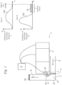
- Figure 1 shows a detector 1 comprising a detector inlet 2, coupled to an analytical apparatus 6 by a sampling inlet 14, such as a pinhole, capillary or membrane inlet, and a sampler 10 arranged to obtain samples of the fluid via the sampling inlet 14 from a sampling volume 16 around the sampling inlet 14.
- a sampling inlet 14 such as a pinhole, capillary or membrane inlet
- the detector inlet 2 shown in Figure 1 comprises a flow passage 20 for carrying a flow of fluid 8 past the sampling inlet 14.
- the detector inlet 2 of Figure 1 comprises a flow provider 18 arranged to flow the fluid into the flow passage, past the sampling inlet 14, and along the flow passage 20 to an outlet.
- the detector inlet 2 may also comprise a heater 4 which may be arranged to heat the flow of fluid 8 upstream of the sampling inlet 14.
- the flow passage 20 comprises a flow director 21 which, in the example of Figure 1 , is provided by a bend in the flow passage 20 arranged to change the direction of the fluid flow upstream from the sampling inlet 14.
- the sampling inlet can be coupled to the flow passage 20 and adapted for collecting samples of the fluid from a sampling volume 16 in the flow passage 20 around the sampling inlet 14.
- the sampler 10 is configured to draw a selected volume of fluid, smaller than the sampling volume 16, through the inlet to provide a sample to the analytical apparatus.
- the sampler 10 may comprise an electromechanical actuator, for example a solenoid driven actuator, and/or a mechanical pump arranged to transfer vapour from the sampling volume 16, through the sampling inlet 14 and into the analytical apparatus.
- the analytical apparatus 6 shown in Figure 1 comprises a mass spectrometer.
- a mass spectrometer may comprise an ioniser, an ion accelerator, a beam focusser, a magnet, and a faraday collector arranged to perform mass spectrometry analysis on samples of vapour.
- a controller 12 is coupled to control the analytical apparatus, the flow provider, the heater, and the sampler.
- the controller 12 may comprise a processor and a memory storing instructions for operation of the detector 1.
- the flow provider 18 flows fluid along the flow passage, and the bend in the flow passage 20 changes the direction of the fluid flow upstream from the sampling inlet 14.
- the spatial distribution of particulates across the fluid flow can be changed to increase a proportion of the particulates which flow past the sampling inlet 14 without entering a volume around the sampling inlet 14.
- This change in distribution is illustrated in Inset A of Figure 1 .
- Inset A illustrates a plot 100 of a spatial distribution of particulates along the line A, the horizontal axis indicates position across the direction of flow of the fluid.
- the plot 100 shown in Inset A of Figure 1 corresponds to a spatial distribution of particulates upstream from the flow director 21.
- Inset B illustrates a plot 102 of a spatial distribution of particulates along the line B, across the direction of flow of the fluid in the region of the sampling volume 16. From a comparison of Inset A and Inset B, it can be seen that the spatial distribution of particulates across the flow of fluid 8 is changed to increase the relative proportion of the particulates carried past the sampling inlet 14 along the flow passage 20 without entering the sampling volume 16.
- the controller 12 can control the sampler 10 to draw a sample from the sampling volume 16 and to provide the sample to the analytical apparatus 6.
- the analytical apparatus 6 illustrated in Figure 1 can then analyse the sample by performing mass spectrometry on the sample.
- the detector inlet 2 of the present disclosure may also be used in other kinds of detectors such as, detectors comprising ion mobility spectrometers, time of flight ion mobility spectrometers, chromatography apparatus and other kinds of analysers for detecting substances of interest.
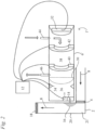
- Figure 2 shows a detector 1 in which the analytical apparatus comprises an ion mobility spectrometer 6' but which is otherwise identical to the apparatus shown in Figure 1 .
- the ion mobility spectrometer of Figure 2 is coupled to a detector inlet 2 by a sampling inlet 14.
- a sampler 10 is arranged to obtain samples of the fluid through the sampling inlet 14 and to provide them to the ion mobility spectrometer 6'.
- the controller 12 may comprise a processor and a memory storing instructions for operation of the detector 1.
- the sampler 10 may comprise an electromechanical actuator, for example a solenoid driven actuator, and/or a mechanical pump arranged to transfer vapour from the sampling volume 16 through the sampling inlet 14 into the analytical apparatus.
- the ion mobility spectrometer 6' may comprise a reaction region 36 in which a sample can be ionised by an ioniser 34.
- the sampler 10 can be operated to obtain a sample from the sampling volume 16 through the sampling inlet 14, and to provide the sample to the reaction region 36.
- sampling inlets 14 include 'pinhole' inlets, which may be approximately 0.7mm in diameter, for example the diameter may be at least 0.4mm, for example at least 0.6mm, for example less than 1.0mm, for example less than 0.8mm.
- a gate electrode 30 may separate the reaction region 36 from a drift chamber 38.
- the gate electrode 30 may comprise an assembly of at least two electrodes, which may be arranged to provide a Bradbury-Nielsen gate.
- the drift chamber 38 can comprise a collector 32 toward the opposite end of the drift chamber 38 from the gate electrode 30 for detecting ions.
- the drift chamber also comprises a drift gas inlet 44, and a drift gas outlet 46 arranged to provide a flow of drift gas along the drift chamber 38 from the ion collector 32 towards the gate 30.
- the sampler 10 can be operated by the controller 12 to obtain fluid from sampling volume 16 through the sampling inlet 14.
- the sampler 10 can also be operated to provide an obtained sample into the reaction region 36 of the spectrometer 6'.
- the reaction region shown in Figure 2 comprises an ioniser 34 for ionising a sample.
- the ioniser 34 may comprise a corona discharge ioniser.
- the drift chamber 38 may comprise drift electrodes 40, 42 for applying an electric field along the drift chamber 38 to move ions towards the collector 32 against the flow of the drift gas.
- the apparatus of Figure 2 is illustrated as comprising two drift electrodes 40, 42, some embodiments may comprise more than two drift electrodes.
- the flow provider 18 can be operated to direct a flow of fluid 8 past the flow director 21 in the flow passage 20 and then past the sampling inlet 14.
- the change in direction it provides varies the distribution of particulates transverse to the direction of flow of the fluid relative to the shape of said distribution upstream of that bend.
- This may provide a depleted region of the cross section of the flow passage 20 through which relatively few particulates flow, the majority of the particulates being carried through other parts of the cross section of the flow passage.
- This depleted region may persist for a distance along the flow passage 20 thereby defining a sampling volume 16 in which the number (e.g. count per unit volume) of particulates is relatively lower than in other regions of the flow passage.
- the sampler 10 can be operated to obtain a sample of fluid from this sampling volume 16 via the sampling inlet 14.
- the obtained sample of fluid can then be provided to an analytical apparatus.
- the analytical apparatus comprises an ion mobility spectrometer 6'.
- detector inlets of the present disclosure find particular application in portable devices which may be used in hostile environments where dust and contaminants are prevalent. These detector inlets may be used with a variety of analytical apparatus, such as the mass spectrometer of Figure 1 and the ion mobility spectrometer of Figure 2 , other kinds of analysers, spectrometers and/or chromatography apparatus. In addition, the detector inlet 2 may have different configurations.
- a detector inlet 2 may comprise flow directors having different structural forms. Each of these flow directors may vary the distribution of particulates in the flow of fluid 8 to provide a sampling volume 16 having a relatively lower concentration of particulates (e.g. a lower mass per unit volume, or particulate count per unit volume).
- the flow director 21 may provide a sampling volume 16 where fluid flow is slow compared to the flow of fluid 8 past the sampling volume 16 along the flow passage. This may be achieved by providing a region of slow flow, and/or by accelerating part of the flow.
- Accelerating may comprise changing the direction of at least a part of the flow of fluid 8 or increasing its speed, or both.
- Providing a region of slow flow may comprise providing a culvert or recess or other sheltered region as in Figure 5 .
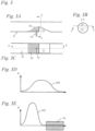
- Figure 3 shows an example of a detector inlet 2 comprising a flow director, a sampling inlet 14, and a flow passage.
- Figure 3 comprises three views of the detector inlet 2, Figure 3A, 3B and 3C.
- Figure 3A shows a section view of the detector inlet 2 from the line indicated as X-X in Figure 3C.
- Figure 3B shows a section view of the detector inlet 2 from the line indicated as Y-Y in Figure 3A.
- Figure 3C shows a section view of the detector inlet 2 from the line indicated as Z-Z in Figure 3B .
- the flow director 21 protrudes into the flow passage 20 from a wall of the flow passage.
- the flow director 21 can direct the flow of fluid to flow only to one side of the flow director.
- the flow director 21 may protrude further into the flow passage 20 toward the flow director's downstream end than towards its upstream end.
- the flow director 21 may have a sloped surface, which may be straight, curved or graduated, to provide a ramp.
- the sampling inlet 14 may be disposed downstream of the flow director 21 to obtain samples from a sheltered sampling volume 16.
- the speed of the fluid flow in the sampling volume 16 may be lower than the speed of fluid flow past the sampling volume 16.
- the speed of the fluid flow past the sampling volume 16 may be higher than the speed of the fluid flow upstream from the flow director.
- Figure 3D illustrates one example of a spatial distribution of particulates across the flow passage 20 upstream from the flow director.
- particulates carried by the fluid flow may be distributed relatively evenly across the width of the flow.
- the distribution shown in Figure 3D is merely exemplary and may be different in different conditions, for example, gravity may skew the distribution in one direction or another depending on the orientation of the device.
- the spatial distribution of particulates across the direction of flow of the fluid may be modified by the flow director.
- the spatial distribution of particulates may be more uneven downstream from the flow director 21 than upstream from it.
- the particulates are more concentrated outside the sampling volume than within it. As a result of this unevenness in the distribution, particulates may be more likely to flow past the inlet without entering the sampling volume 16.
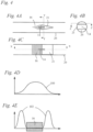
- Figure 4 shows another example of a flow director.
- Figure 4 comprises three views of a detector inlet 2, Figure 4A, 4B and 4C.
- Figure 4A shows a section view of the detector inlet from the line indicated as X-X in Figure 4C.
- Figure 4B shows a section view of the detector inlet 2 from the line indicated as Y-Y in Figure 4A.
- Figure 4C shows a section view of the detector inlet 2 from the line indicated as Z-Z in Figure 4B .
- the flow director 21 may be arranged to separate the fluid flow into at least two separate flow paths, separated by the flow director.
- the flow director 21 of Figure 3B may be arranged mid-flow, spanning across the flow passage, and coupled to two walls of the flow passage.
- the flow director 21 shown in Figure 4B may be tapered so that it is narrower towards its upstream end than it is towards its downstream end.
- the flow director 21 provides a sheltered sampling volume 16 at its downstream end, and the sampling inlet 14 may be arranged on the downstream end of the flow director. The passage of fluid flow on both sides of this flow director 21 may reduce the tendency of particles to accumulate around the sampling inlet 14.
- Figure 4D illustrates one example of a spatial distribution of particulates across the flow passage 20 upstream from the flow director.
- Figure 4E illustrates a shape of a distribution of particulates across the direction of the fluid flow in the region of the sampling volume 16. It can be seen from Figure 4E that the flow director 21 can increase the probability that particulates will flow around the sampling volume 16, rather than flowing through it.
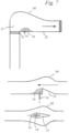
- Figure 5 illustrates another example of a detector inlet.
- Figure 5 comprises three views of a detector inlet, Figure 5A, 5B and 5C.
- Figure 5A shows a section view of the detector inlet 2 from the line indicated as X-X in Figure 5C.
- Figure 5B shows a section view of the detector inlet 2 from the line indicated as Y-Y in Figure 5A.
- Figure 5C shows a section view of the detector inlet 2 from the line indicated as Z-Z in Figure 5B .
- the flow director 21 is provided by a variation in cross section of the flow passage.
- the flow director 21 comprises a recess in a wall of the flow passage, and the sampling inlet 14 is arranged in the recess.
- the sampling inlet 14 may be arranged in the upstream wall of the recess, so the flow can be directed away from the sampling inlet 14. Accordingly, the fluid flow can be directed past the recess (and the sampling volume), thereby reducing the probability that particulates carried by the flow of fluid will enter the sampling volume 16.
- Figure 5D illustrates one example of a spatial distribution of particulates across the flow passage 20 upstream from the flow director.
- Figure 5E illustrates the spatial distribution of particulates across the direction of the flow downstream of the flow director 21 where the flow passes the recess.
- Figure 5E illustrates a lower number of particulates in the recess than in the fluid flowing past it, thereby illustrating one way in which the shape of the spatial distribution of particulates may be changed by a flow director.
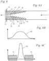
- Figure 6A shows another example of a flow director.
- the flow director 21 comprises a series of foils 50, 52, 54, 56, 58, 60, 62.
- the foils, 50-62 may be ring shaped and may be arranged on a common axis.
- Each foil 50-62 may have an aerofoil type profile, or be otherwise configured, for example by being shaped, profiled and/or angled, to funnel particulates inside the foils in preference to fluid.
- the foils 50-62 may be configured, for example by being shaped, profiled and/or angled, to preferentially direct fluid flow outside of the foils.
- the foils 50-62 may be spaced apart in the direction of flow of the fluid. At the upstream end of this flow director 21, one of the foils 50 may span most or all of the width of the flow passage. The span of the downstream foils 52, 54, 56, 58, 60, 62 may become successively smaller, to provide a tapered structure. Each of the foils may be pitched (e.g. at an acute angle) relative to the direction of flow of the fluid along the flow passage 20. The foils may all have the same pitch, or the pitch may be varied. The foil 62 at the downstream end of the flow director may be smaller than the other foils.
- the sampling inlet 14 illustrated in Figure 6 is arranged to obtain samples of fluid from a sampling volume 16 downstream from this last, most downstream, foil in the series of foils.
- the foils may be heated to inhibit the accumulation of substances on the foils, and/or to vapourise aerosols carried by the flow of air along the detector inlet.
- the foils of course need not be circular rings and may be non-circular, for example oval, tapered, rectangular, square or any other shape.
- the foils may be arranged to be symmetrical about a common axis, for example an axis aligned with the direction of flow of fluid along the flow passage.
- one or more of the foils may be helical, or all of the circular foils may be replaced by a single helical foil.
- a helical foil may spiral inward along the flow passage so that it has a greater diameter at its upstream end than at its downstream end.
- Figure 6B illustrates one example of a spatial distribution of particulates across the flow passage 20 upstream from the flow director foils 50-62 of Figure 6A .
- Figure 6C illustrates the spatial distribution of particulates across the direction of the flow downstream of the flow director foils 50-62 where the flow passes the inlet 14. As shown in Figure 6C , in this region, downstream from the foils 50-62, the particulates are concentrated into a narrow region of the flow passage.
- Some flow directors may provide a reduction in the cross section of the flow passage 20 through which the fluid can flow.
- the flow director may cause a change in direction of the fluid flow which could cause undesirable concentration and/or deposition of particulates in a region of the flow passage.
- Figure 7 illustrates some embodiments of detector inlets in which the flow passage 20 comprises variations 60 in the shape and/or area of its cross section to accommodate changes in flow caused by the flow director 21.
- These variations 60 in cross section may be arranged at least partially downstream of the flow director 21, for example at least part of the variation 60 in cross section may be arranged downstream from the upstream end of the flow director 21.
- these variations in cross section may be configured to promote laminar flow of fluid past the flow director.
- the variations comprise a bulge in at least one wall of the flow passage.
- the bulge may comprise curved, sloped or graduated portions arranged to accommodate variations in fluid flow caused by the flow director.
- the controller 12 of the apparatus may be provided by any appropriate processing means such as an FPGA, an ASIC, a general purpose processor, or an appropriate arrangement of logic gates.
- the flow provider 18 may comprise pump or a fan or any other device capable of inhaling a flow of fluid along the flow passage.
- the heater 4 described with reference to Figure 1 may be arranged in any of the other detector inlets described above to heat the flow of fluid upstream from the sampling inlet 14.
- Such heaters 4 may comprise a resistive heater, such as a tape or membrane heater, or it may be provided by a source of radiative heat such as an infrared light source, for example a laser. In some examples the heater may comprise a jet of heated air.
- a resistive heater such as a tape or membrane heater
- a source of radiative heat such as an infrared light source, for example a laser.
- the heater may comprise a jet of heated air.
- analytical apparatus such as mass spectrometers and ion mobility spectrometers, but other kinds of analytical apparatus may also be used. Other examples and variations will be apparent to the skilled addressee in the context of the present disclosure. It will also be apparent that features of each of the embodiments described with reference to each of the drawings may be combined, individually or otherwise, with some or all or the features of any of the other embodiments. Method features may be implemented by suitably configured apparatus, and the methods of operation described with reference to particular types of apparatus are intended as an independent disclosure of the methods themselves
Landscapes
- Life Sciences & Earth Sciences (AREA)
- Health & Medical Sciences (AREA)
- Chemical & Material Sciences (AREA)
- Engineering & Computer Science (AREA)
- Physics & Mathematics (AREA)
- General Physics & Mathematics (AREA)
- Pathology (AREA)
- Analytical Chemistry (AREA)
- Biochemistry (AREA)
- General Health & Medical Sciences (AREA)
- Immunology (AREA)
- Biomedical Technology (AREA)
- Molecular Biology (AREA)
- Food Science & Technology (AREA)
- Medicinal Chemistry (AREA)
- Combustion & Propulsion (AREA)
- Spectroscopy & Molecular Physics (AREA)
- Other Investigation Or Analysis Of Materials By Electrical Means (AREA)
- Sampling And Sample Adjustment (AREA)
- Optical Measuring Cells (AREA)
Claims (10)
- Detektor, der Folgendes umfasst:
eine analytische Vorrichtung (6) zum Erfassen einer Substanz von Interesse und einen Detektoreinlass (2), wobei der Detektoreinlass (2) Folgendes umfasst:eine Strömungsleitung (20) zum Führen eines Fluidstroms, der von einem Strömungserzeuger bereitgestellt wird, wobei die Strömungsleitung (20) ein Probenahmevolumen (16) umfasst;und einen Strömungsleiter (21), der dafür ausgelegt ist, eine räumliche Verteilung von Partikeln quer zur Strömungsrichtung des Fluids relativ zur Form der genannten Verteilung stromaufwärts des Strömungsleiters (21) zu variieren, um einen verarmten Bereich des Querschnitts der Strömungsleitung (20) bereitzustellen, durch den relativ wenige Partikel strömen, während der Großteil der Partikel durch andere Teile des Querschnitts der Strömungsleitung (20) transportiert wird, wobei der verarmte Bereich das Probenahmevolumen (16) definiert;einen Probenahmeeinlass (14), der dafür ausgelegt ist, Proben des Fluids aus dem Probenahmevolumen zu sammeln, wenn das Fluid am Probenahmeeinlass (14) vorbeiströmt, und um die Proben der Analysevorrichtung zuzuführen, wobei der Fluidstrom Partikel mit sich führt;wobei der Detektor dadurch gekennzeichnet ist, dass der Probenahmeeinlass (14) mindestens einen Lochblenden-, Membran- oder Kapillareinlass umfasst und der Strömungsleiter (21) durch eine Biegung in Richtung der Strömungsleitung (20) bereitgestellt wird. - Detektor nach Anspruch 1, wobei der Strömungsleiter (21) so ausgelegt ist, dass die Geschwindigkeit eines Teils der Fluidströmung, die an dem Probenahmevolumen (16) entlang der Strömungsleitung vorbeiströmt, größer ist als die Strömungsgeschwindigkeit des Fluids stromaufwärts von dem Probenahmevolumen (16).
- Detektor nach einem der vorhergehenden Ansprüche, der einen Probenehmer (10) umfasst, der mit dem Probenahmeeinlass (14) gekoppelt ist und dafür konfiguriert ist, ein ausgewähltes Volumen an Fluid aus dem Probenahmevolumen (16) durch den Probenahmeeinlass (14) zu ziehen, wobei das ausgewählte Volumen an Fluid kleiner ist als das Probenahmevolumen (16).
- Detektor nach einem der vorhergehenden Ansprüche, der eine Heizvorrichtung (4) zum Erwärmen des Fluidstroms umfasst, wobei die Heizvorrichtung (4) beispielsweise dafür ausgelegt ist, den Fluidstrom stromaufwärts vom Probenahmeeinlass zu erwärmen.
- Detektor nach einem der vorhergehenden Ansprüche, wobei mindestens eine der Formen oder Flächen eines Querschnitts der Strömungsleitung (20) stromabwärts vom Strömungsleiter (21) modifiziert ist, um Änderungen im Fluidstrom, die durch den Strömungsleiter (21) verursacht werden, auszugleichen.
- Detektor nach einem der vorhergehenden Ansprüche, wobei die Analysevorrichtung (6) mindestens eines von einem Spektrometer und einer Chromatographievorrichtung umfasst.
- Verfahren zum Erfassen einer interessierenden Substanz in einer Dampfprobe, die aus einem Fluidstrom erhalten wird, der Partikel trägt, wobei das Verfahren Folgendes umfasst:Bereitstellen einer Strömungsleitung, die ein Probenahmevolumen und einen Strömungsleiter umfasst, der durch eine Biegung in Richtung der Strömungsleitung bereitgestellt wird;Leiten des Fluidstroms, der durch einen Strömungsgeber bereitgestellt wird, an einem Probenahmeeinlass vorbei, wobei der Probenahmeeinlass (14) mindestens einen Lochblendeneinlass, einen Membraneinlass und/oder einen Kapillareinlass umfasst;Variieren der Form einer Verteilung von Partikeln quer zur Strömungsrichtung relativ zur Form der genannten Verteilung stromaufwärts des Probenahmeeinlasses (14), so dass die von der Strömung mitgeführten Partikel daran gehindert werden, durch das Probenahmevolumen (16) um den Probenahmeeinlass (14) herum zu strömen;Entnehmen mindestens einer Probe aus dem Probenahmevolumen (16) über den Probenahmeeinlass (14); undBereitstellen der Probe für eine Analysevorrichtung (6), die dafür konfiguriert ist, die interessierende Substanz zu erfassen.
- Verfahren nach Anspruch 7, wobei das Volumen der erhaltenen Probe so gewählt wird, dass es kleiner als das Probenahmevolumen (16) ist.
- Verfahren nach Anspruch 7, das das Erwärmen des Fluidstroms stromaufwärts vom Probenahmeeinlass (14) umfasst, um mindestens einige der Partikel zu verdampfen.
- Verfahren nach einem der Ansprüche 7 bis 9, wobei die Analysevorrichtung (6) mindestens eines von einem Spektrometer und einer Chromatographievorrichtung umfasst.
Priority Applications (1)
| Application Number | Priority Date | Filing Date | Title |
|---|---|---|---|
| EP24217293.0A EP4521094A3 (de) | 2014-03-27 | 2015-03-24 | Detektoreinlass und probenahmeverfahren |
Applications Claiming Priority (2)
| Application Number | Priority Date | Filing Date | Title |
|---|---|---|---|
| GBGB1405561.0A GB201405561D0 (en) | 2014-03-27 | 2014-03-27 | Detector inlet and sampling method |
| PCT/GB2015/050870 WO2015145132A1 (en) | 2014-03-27 | 2015-03-24 | Detector inlet and sampling method |
Related Child Applications (1)
| Application Number | Title | Priority Date | Filing Date |
|---|---|---|---|
| EP24217293.0A Division EP4521094A3 (de) | 2014-03-27 | 2015-03-24 | Detektoreinlass und probenahmeverfahren |
Publications (3)
| Publication Number | Publication Date |
|---|---|
| EP3123166A1 EP3123166A1 (de) | 2017-02-01 |
| EP3123166C0 EP3123166C0 (de) | 2024-12-04 |
| EP3123166B1 true EP3123166B1 (de) | 2024-12-04 |
Family
ID=50737567
Family Applications (2)
| Application Number | Title | Priority Date | Filing Date |
|---|---|---|---|
| EP24217293.0A Pending EP4521094A3 (de) | 2014-03-27 | 2015-03-24 | Detektoreinlass und probenahmeverfahren |
| EP15717208.1A Active EP3123166B1 (de) | 2014-03-27 | 2015-03-24 | Detektoreinlass und probenahmeverfahren |
Family Applications Before (1)
| Application Number | Title | Priority Date | Filing Date |
|---|---|---|---|
| EP24217293.0A Pending EP4521094A3 (de) | 2014-03-27 | 2015-03-24 | Detektoreinlass und probenahmeverfahren |
Country Status (11)
| Country | Link |
|---|---|
| US (3) | US10613065B2 (de) |
| EP (2) | EP4521094A3 (de) |
| JP (1) | JP2017509906A (de) |
| KR (2) | KR102707869B1 (de) |
| CN (1) | CN106662510B (de) |
| CA (1) | CA2944111C (de) |
| GB (3) | GB201405561D0 (de) |
| MX (1) | MX380577B (de) |
| PL (1) | PL3123166T3 (de) |
| RU (1) | RU2721775C2 (de) |
| WO (1) | WO2015145132A1 (de) |
Families Citing this family (16)
| Publication number | Priority date | Publication date | Assignee | Title |
|---|---|---|---|---|
| GB2542824B (en) * | 2015-09-30 | 2020-06-10 | Smiths Detection Watford Ltd | Apparatus and Method |
| GB2542827B (en) * | 2015-09-30 | 2019-10-02 | Smiths Detection Watford Ltd | Sampling method and apparatus with heating to vapourise components |
| US10522252B2 (en) | 2017-06-16 | 2019-12-31 | Carefusion 303, Inc. | Opioid management system |
| US11081220B2 (en) | 2018-02-02 | 2021-08-03 | Carefusion 303, Inc. | System and method for dispensing medication |
| DE102018103530A1 (de) * | 2018-02-16 | 2019-08-22 | Endress+Hauser Conducta Gmbh+Co. Kg | Analysegerät zur Bestimmung einer eine Silikatkonzentration in einer Probenflüssigkeit repräsentierenden Messgröße |
| CA3099146A1 (en) | 2018-05-04 | 2019-11-07 | Carefusion 303, Inc. | Peer community based anomalous behavior detection |
| DE112020000335T5 (de) | 2019-01-07 | 2021-10-21 | Carefusion 303, Inc. | Auf maschinellem lernen basierende sicherheitssteuerung |
| US11984212B2 (en) | 2019-01-10 | 2024-05-14 | Carefusion 303, Inc. | System for monitoring dose pattern and patient response |
| US10980940B2 (en) | 2019-01-18 | 2021-04-20 | Carefusion 303, Inc. | Medication tracking system |
| US12437862B2 (en) | 2019-09-27 | 2025-10-07 | Carefusion 303, Inc. | Rare instance analytics for diversion detection |
| EP3832302A1 (de) * | 2019-12-02 | 2021-06-09 | Aerosol d.o.o. | Heizkammer zur messung von kohlenstoffhaltigem aerosol und vorrichtung mit besagter kammer |
| CN115380299A (zh) | 2020-02-24 | 2022-11-22 | 康尔福盛303公司 | 模块化见证装置 |
| KR102132977B1 (ko) | 2020-02-25 | 2020-07-14 | 영인에이스 주식회사 | 질량분석기 |
| WO2021231438A1 (en) | 2020-05-14 | 2021-11-18 | Carefusion 303, Inc. | Wasting station for medications |
| US12482554B2 (en) | 2021-02-26 | 2025-11-25 | Carefusion 303, Inc. | Dosage normalization for detection of anomalous behavior |
| GB2625142B (en) * | 2022-12-08 | 2025-01-29 | Smiths Detection Watford Ltd | Apparatus and Method |
Citations (2)
| Publication number | Priority date | Publication date | Assignee | Title |
|---|---|---|---|---|
| US4481833A (en) * | 1982-12-27 | 1984-11-13 | Uop Inc. | Particle excluding sample probe |
| WO2013175947A1 (ja) * | 2012-05-23 | 2013-11-28 | 株式会社日立製作所 | 微粒子検出装置及びセキュリティゲート |
Family Cites Families (33)
| Publication number | Priority date | Publication date | Assignee | Title |
|---|---|---|---|---|
| US3710561A (en) * | 1969-12-24 | 1973-01-16 | Amf Inc | Apparatus for separating solid particles suspended in a gaseous stream |
| US3757367A (en) * | 1971-02-08 | 1973-09-11 | Chemetron Corp | Method for carbon dioxide snow separation |
| CA1036387A (en) * | 1974-03-20 | 1978-08-15 | Thomas J. Barthlow | Sampling and analysis of gas from a stream of fluid containing solid particles |
| US3933047A (en) * | 1974-08-15 | 1976-01-20 | Cabot Corporation | Method and means for gas sampling in mass spectrometry |
| US4170455A (en) * | 1976-03-11 | 1979-10-09 | Rockwell International Corporation | Gas monitoring method and apparatus therefor |
| DE3422062A1 (de) * | 1984-06-14 | 1985-12-19 | Kernforschungszentrum Karlsruhe Gmbh, 7500 Karlsruhe | Verfahren zur langzeitbestimmung und dauerueberwachung des schadstoffgehaltes von feststoffbeladenen abgasstroemen |
| JP3258488B2 (ja) * | 1994-03-23 | 2002-02-18 | 日本碍子株式会社 | 酸素検出装置 |
| JPH0828323A (ja) * | 1994-07-13 | 1996-01-30 | Sanshin Ind Co Ltd | エンジンの空燃比制御装置 |
| DE4438267A1 (de) * | 1994-10-26 | 1996-05-02 | Jan Dipl Ing Boie | Scepter-Heißgassonde |
| JPH08285832A (ja) | 1995-04-18 | 1996-11-01 | Shimamura Keiki Seisakusho:Kk | 液体クロマトグラフィー用検出器のための液体試料前処理方法及びその装置 |
| JP3290893B2 (ja) * | 1996-03-19 | 2002-06-10 | フロンティア・ラボ株式会社 | 気相成分分析装置 |
| JP3448157B2 (ja) * | 1996-05-23 | 2003-09-16 | 中国電力株式会社 | ガス採取用プローブ管 |
| GB9810866D0 (en) * | 1998-05-20 | 1998-07-22 | Boc Group Plc | Furnace waste gas sampling |
| JP2000249631A (ja) | 1999-03-03 | 2000-09-14 | Mitsubishi Electric Corp | 有機化合物捕集装置 |
| GB9913443D0 (en) * | 1999-06-09 | 1999-08-11 | Air Dispersions Ltd | Sampling devices |
| US6478856B1 (en) * | 2000-05-26 | 2002-11-12 | Stephen Leibholz | Apparatus and method for collection, sorting, concentrating and impinging particles on a surface |
| US6465776B1 (en) | 2000-06-02 | 2002-10-15 | Board Of Regents, The University Of Texas System | Mass spectrometer apparatus for analyzing multiple fluid samples concurrently |
| JP2002243598A (ja) | 2001-02-21 | 2002-08-28 | Horiba Ltd | 分析計 |
| US6845676B2 (en) * | 2001-12-14 | 2005-01-25 | Darrell Lee Bigalke | Continuous fluid sampler and method |
| US7022992B2 (en) * | 2002-01-17 | 2006-04-04 | American Air Liquide, Inc. | Method and apparatus for real-time monitoring of furnace flue gases |
| DE10309354A1 (de) * | 2003-03-03 | 2004-09-16 | Kampmann, Harry, Dipl.-Ing. | Vorrichtung zum Entnehmen von Gasproben aus einem Gaskanal |
| ES2312977T3 (es) * | 2003-03-10 | 2009-03-01 | The Johns Hopkins University | Metodo y aparato para la monitorizacion bioprospeccion medio ambientales. |
| CN101135628A (zh) | 2003-10-23 | 2008-03-05 | 马丁·T·科尔 | 颗粒探测器及其方法 |
| GB0621990D0 (en) | 2006-11-04 | 2006-12-13 | Smiths Group Plc | Detection |
| US9476531B2 (en) * | 2007-07-27 | 2016-10-25 | Dieterich Standard, Inc. | Elliptical flow conditioning pipe elbow |
| DE102007040898A1 (de) | 2007-08-24 | 2009-10-01 | Dürr Systems GmbH | Verfahren und Vorrichtung zum Einbringen von Hilfsmaterial |
| CA2701352A1 (en) * | 2007-10-02 | 2009-04-09 | Ann-Charlotte Almstrand | Collection and measurement of exhaled particles |
| WO2009061863A2 (en) | 2007-11-06 | 2009-05-14 | Rapiscan Security Products, Inc. | Hand-held explosive detection system |
| US8087307B2 (en) * | 2009-02-10 | 2012-01-03 | General Electric Company | Removal of particulates from gas sampling stream |
| US20120105839A1 (en) | 2009-07-11 | 2012-05-03 | Enertechnix, Inc | Progressive Cut-Size Particle Trap and Aerosol Collection Apparatus |
| EP2542347A4 (de) | 2010-03-05 | 2016-05-11 | Xtralis Technologies Ltd | Partikelabscheider |
| GB2487436B (en) | 2011-01-24 | 2013-10-09 | Framo Eng As | Conduit for a hydrocarbon transport pipeline,related method and system |
| US9744490B1 (en) * | 2012-04-06 | 2017-08-29 | Enertechnix, Inc. | Trapped vortex particle-to-vapor converter |
-
2014
- 2014-03-27 GB GBGB1405561.0A patent/GB201405561D0/en not_active Ceased
-
2015
- 2015-03-24 WO PCT/GB2015/050870 patent/WO2015145132A1/en not_active Ceased
- 2015-03-24 EP EP24217293.0A patent/EP4521094A3/de active Pending
- 2015-03-24 EP EP15717208.1A patent/EP3123166B1/de active Active
- 2015-03-24 JP JP2017501513A patent/JP2017509906A/ja active Pending
- 2015-03-24 GB GB1504963.8A patent/GB2530124B/en active Active
- 2015-03-24 KR KR1020227035320A patent/KR102707869B1/ko active Active
- 2015-03-24 CN CN201580028167.1A patent/CN106662510B/zh active Active
- 2015-03-24 CA CA2944111A patent/CA2944111C/en active Active
- 2015-03-24 GB GB1805813.1A patent/GB2563973B/en active Active
- 2015-03-24 US US15/129,525 patent/US10613065B2/en active Active
- 2015-03-24 KR KR1020167030050A patent/KR102455026B1/ko active Active
- 2015-03-24 MX MX2016012658A patent/MX380577B/es unknown
- 2015-03-24 RU RU2016139341A patent/RU2721775C2/ru active
- 2015-03-24 PL PL15717208.1T patent/PL3123166T3/pl unknown
-
2020
- 2020-03-02 US US16/806,273 patent/US11150228B2/en active Active
-
2021
- 2021-10-19 US US17/504,641 patent/US11774421B2/en active Active
Patent Citations (2)
| Publication number | Priority date | Publication date | Assignee | Title |
|---|---|---|---|---|
| US4481833A (en) * | 1982-12-27 | 1984-11-13 | Uop Inc. | Particle excluding sample probe |
| WO2013175947A1 (ja) * | 2012-05-23 | 2013-11-28 | 株式会社日立製作所 | 微粒子検出装置及びセキュリティゲート |
Also Published As
| Publication number | Publication date |
|---|---|
| GB201405561D0 (en) | 2014-05-14 |
| GB201504963D0 (en) | 2015-05-06 |
| EP3123166C0 (de) | 2024-12-04 |
| GB2563973A (en) | 2019-01-02 |
| CN106662510A (zh) | 2017-05-10 |
| KR20220141926A (ko) | 2022-10-20 |
| US20200271631A1 (en) | 2020-08-27 |
| EP4521094A3 (de) | 2025-05-14 |
| KR20160146755A (ko) | 2016-12-21 |
| RU2016139341A (ru) | 2018-04-27 |
| EP4521094A2 (de) | 2025-03-12 |
| EP3123166A1 (de) | 2017-02-01 |
| GB201805813D0 (en) | 2018-05-23 |
| GB2563973B (en) | 2019-04-17 |
| MX2016012658A (es) | 2017-04-13 |
| CA2944111C (en) | 2024-05-21 |
| KR102707869B1 (ko) | 2024-09-19 |
| MX380577B (es) | 2025-03-12 |
| US20170108480A1 (en) | 2017-04-20 |
| WO2015145132A1 (en) | 2015-10-01 |
| CA2944111A1 (en) | 2015-10-01 |
| GB2530124B (en) | 2018-05-30 |
| CN106662510B (zh) | 2020-12-11 |
| US20220146480A1 (en) | 2022-05-12 |
| US11774421B2 (en) | 2023-10-03 |
| RU2721775C2 (ru) | 2020-05-22 |
| US11150228B2 (en) | 2021-10-19 |
| JP2017509906A (ja) | 2017-04-06 |
| RU2016139341A3 (de) | 2018-10-24 |
| US10613065B2 (en) | 2020-04-07 |
| KR102455026B1 (ko) | 2022-10-13 |
| PL3123166T3 (pl) | 2025-02-10 |
| GB2530124A (en) | 2016-03-16 |
Similar Documents
| Publication | Publication Date | Title |
|---|---|---|
| US11774421B2 (en) | Detector inlet and sampling method | |
| US11585735B2 (en) | Detector with detector inlet for sampling gaseous fluid | |
| US20160141145A1 (en) | Micro Machined Two Dimensional Faraday Collector Grid | |
| KR102700491B1 (ko) | 가스 유체 샘플링 장치 및 방법 | |
| JP2025527610A (ja) | サンプリングシステム、検出装置、並びに、当該サンプリングシステム及び/又は検出装置の使用方法 | |
| KR20250117798A (ko) | 검출기 입구 및 샘플링 방법 | |
| EP4627314A1 (de) | Detektoreinlassvorrichtung und -verfahren |
Legal Events
| Date | Code | Title | Description |
|---|---|---|---|
| STAA | Information on the status of an ep patent application or granted ep patent |
Free format text: STATUS: THE INTERNATIONAL PUBLICATION HAS BEEN MADE |
|
| PUAI | Public reference made under article 153(3) epc to a published international application that has entered the european phase |
Free format text: ORIGINAL CODE: 0009012 |
|
| STAA | Information on the status of an ep patent application or granted ep patent |
Free format text: STATUS: REQUEST FOR EXAMINATION WAS MADE |
|
| 17P | Request for examination filed |
Effective date: 20161027 |
|
| AK | Designated contracting states |
Kind code of ref document: A1 Designated state(s): AL AT BE BG CH CY CZ DE DK EE ES FI FR GB GR HR HU IE IS IT LI LT LU LV MC MK MT NL NO PL PT RO RS SE SI SK SM TR |
|
| AX | Request for extension of the european patent |
Extension state: BA ME |
|
| DAV | Request for validation of the european patent (deleted) | ||
| DAX | Request for extension of the european patent (deleted) | ||
| STAA | Information on the status of an ep patent application or granted ep patent |
Free format text: STATUS: EXAMINATION IS IN PROGRESS |
|
| 17Q | First examination report despatched |
Effective date: 20200205 |
|
| REG | Reference to a national code |
Ref country code: DE Free format text: PREVIOUS MAIN CLASS: G01N0033000000 Ref country code: DE Ref legal event code: R079 Ref document number: 602015090562 Country of ref document: DE Free format text: PREVIOUS MAIN CLASS: G01N0033000000 Ipc: G01N0001220000 |
|
| GRAP | Despatch of communication of intention to grant a patent |
Free format text: ORIGINAL CODE: EPIDOSNIGR1 |
|
| RIC1 | Information provided on ipc code assigned before grant |
Ipc: G01N 1/22 20060101AFI20240522BHEP |
|
| STAA | Information on the status of an ep patent application or granted ep patent |
Free format text: STATUS: GRANT OF PATENT IS INTENDED |
|
| RAP3 | Party data changed (applicant data changed or rights of an application transferred) |
Owner name: SMITHS DETECTION-WATFORD LIMITED |
|
| INTG | Intention to grant announced |
Effective date: 20240627 |
|
| RAP3 | Party data changed (applicant data changed or rights of an application transferred) |
Owner name: SMITHS DETECTION-WATFORD LIMITED |
|
| GRAS | Grant fee paid |
Free format text: ORIGINAL CODE: EPIDOSNIGR3 |
|
| GRAA | (expected) grant |
Free format text: ORIGINAL CODE: 0009210 |
|
| STAA | Information on the status of an ep patent application or granted ep patent |
Free format text: STATUS: THE PATENT HAS BEEN GRANTED |
|
| AK | Designated contracting states |
Kind code of ref document: B1 Designated state(s): AL AT BE BG CH CY CZ DE DK EE ES FI FR GB GR HR HU IE IS IT LI LT LU LV MC MK MT NL NO PL PT RO RS SE SI SK SM TR |
|
| RAP3 | Party data changed (applicant data changed or rights of an application transferred) |
Owner name: SMITHS DETECTION-WATFORD LIMITED |
|
| REG | Reference to a national code |
Ref country code: GB Ref legal event code: FG4D |
|
| RIN1 | Information on inventor provided before grant (corrected) |
Inventor name: FOURNIER, FREDERIC Inventor name: EASTON, MATTHEW Inventor name: GRANT, BRUCE Inventor name: CLARK, ALASTAIR |
|
| REG | Reference to a national code |
Ref country code: CH Ref legal event code: EP |
|
| REG | Reference to a national code |
Ref country code: DE Ref legal event code: R096 Ref document number: 602015090562 Country of ref document: DE |
|
| REG | Reference to a national code |
Ref country code: IE Ref legal event code: FG4D |
|
| U01 | Request for unitary effect filed |
Effective date: 20241216 |
|
| U07 | Unitary effect registered |
Designated state(s): AT BE BG DE DK EE FI FR IT LT LU LV MT NL PT RO SE SI Effective date: 20250109 |
|
| U20 | Renewal fee for the european patent with unitary effect paid |
Year of fee payment: 11 Effective date: 20250205 |
|
| PG25 | Lapsed in a contracting state [announced via postgrant information from national office to epo] |
Ref country code: HR Free format text: LAPSE BECAUSE OF FAILURE TO SUBMIT A TRANSLATION OF THE DESCRIPTION OR TO PAY THE FEE WITHIN THE PRESCRIBED TIME-LIMIT Effective date: 20241204 |
|
| PG25 | Lapsed in a contracting state [announced via postgrant information from national office to epo] |
Ref country code: ES Free format text: LAPSE BECAUSE OF FAILURE TO SUBMIT A TRANSLATION OF THE DESCRIPTION OR TO PAY THE FEE WITHIN THE PRESCRIBED TIME-LIMIT Effective date: 20241204 |
|
| PG25 | Lapsed in a contracting state [announced via postgrant information from national office to epo] |
Ref country code: NO Free format text: LAPSE BECAUSE OF FAILURE TO SUBMIT A TRANSLATION OF THE DESCRIPTION OR TO PAY THE FEE WITHIN THE PRESCRIBED TIME-LIMIT Effective date: 20250304 |
|
| PG25 | Lapsed in a contracting state [announced via postgrant information from national office to epo] |
Ref country code: GR Free format text: LAPSE BECAUSE OF FAILURE TO SUBMIT A TRANSLATION OF THE DESCRIPTION OR TO PAY THE FEE WITHIN THE PRESCRIBED TIME-LIMIT Effective date: 20250305 |
|
| PGFP | Annual fee paid to national office [announced via postgrant information from national office to epo] |
Ref country code: PL Payment date: 20250113 Year of fee payment: 11 |
|
| PGFP | Annual fee paid to national office [announced via postgrant information from national office to epo] |
Ref country code: GB Payment date: 20250102 Year of fee payment: 11 |
|
| PG25 | Lapsed in a contracting state [announced via postgrant information from national office to epo] |
Ref country code: RS Free format text: LAPSE BECAUSE OF FAILURE TO SUBMIT A TRANSLATION OF THE DESCRIPTION OR TO PAY THE FEE WITHIN THE PRESCRIBED TIME-LIMIT Effective date: 20250304 |
|
| PG25 | Lapsed in a contracting state [announced via postgrant information from national office to epo] |
Ref country code: SM Free format text: LAPSE BECAUSE OF FAILURE TO SUBMIT A TRANSLATION OF THE DESCRIPTION OR TO PAY THE FEE WITHIN THE PRESCRIBED TIME-LIMIT Effective date: 20241204 |
|
| PG25 | Lapsed in a contracting state [announced via postgrant information from national office to epo] |
Ref country code: IS Free format text: LAPSE BECAUSE OF FAILURE TO SUBMIT A TRANSLATION OF THE DESCRIPTION OR TO PAY THE FEE WITHIN THE PRESCRIBED TIME-LIMIT Effective date: 20250404 |
|
| PG25 | Lapsed in a contracting state [announced via postgrant information from national office to epo] |
Ref country code: SK Free format text: LAPSE BECAUSE OF FAILURE TO SUBMIT A TRANSLATION OF THE DESCRIPTION OR TO PAY THE FEE WITHIN THE PRESCRIBED TIME-LIMIT Effective date: 20241204 |
|
| PG25 | Lapsed in a contracting state [announced via postgrant information from national office to epo] |
Ref country code: CZ Free format text: LAPSE BECAUSE OF FAILURE TO SUBMIT A TRANSLATION OF THE DESCRIPTION OR TO PAY THE FEE WITHIN THE PRESCRIBED TIME-LIMIT Effective date: 20241204 |
|
| PLBE | No opposition filed within time limit |
Free format text: ORIGINAL CODE: 0009261 |
|
| STAA | Information on the status of an ep patent application or granted ep patent |
Free format text: STATUS: NO OPPOSITION FILED WITHIN TIME LIMIT |
|
| PG25 | Lapsed in a contracting state [announced via postgrant information from national office to epo] |
Ref country code: MC Free format text: LAPSE BECAUSE OF FAILURE TO SUBMIT A TRANSLATION OF THE DESCRIPTION OR TO PAY THE FEE WITHIN THE PRESCRIBED TIME-LIMIT Effective date: 20241204 |
|
| REG | Reference to a national code |
Ref country code: CH Ref legal event code: L10 Free format text: ST27 STATUS EVENT CODE: U-0-0-L10-L00 (AS PROVIDED BY THE NATIONAL OFFICE) Effective date: 20251015 |
|
| REG | Reference to a national code |
Ref country code: CH Ref legal event code: H13 Free format text: ST27 STATUS EVENT CODE: U-0-0-H10-H13 (AS PROVIDED BY THE NATIONAL OFFICE) Effective date: 20251023 |
|
| 26N | No opposition filed |
Effective date: 20250905 |