EP3121661A1 - Direkter uhrhemmungsmechanismus mit konstanter kraft - Google Patents
Direkter uhrhemmungsmechanismus mit konstanter kraft Download PDFInfo
- Publication number
- EP3121661A1 EP3121661A1 EP15177689.5A EP15177689A EP3121661A1 EP 3121661 A1 EP3121661 A1 EP 3121661A1 EP 15177689 A EP15177689 A EP 15177689A EP 3121661 A1 EP3121661 A1 EP 3121661A1
- Authority
- EP
- European Patent Office
- Prior art keywords
- wheel
- anchor
- rest
- escapement
- escape
- Prior art date
- Legal status (The legal status is an assumption and is not a legal conclusion. Google has not performed a legal analysis and makes no representation as to the accuracy of the status listed.)
- Granted
Links
- 230000007246 mechanism Effects 0.000 title claims abstract description 60
- 230000015572 biosynthetic process Effects 0.000 claims description 22
- 238000005755 formation reaction Methods 0.000 claims description 22
- 210000003423 ankle Anatomy 0.000 claims description 6
- 230000000694 effects Effects 0.000 claims description 6
- 238000006073 displacement reaction Methods 0.000 claims description 3
- 229940082150 encore Drugs 0.000 description 5
- 230000010355 oscillation Effects 0.000 description 4
- 235000021183 entrée Nutrition 0.000 description 3
- 230000000284 resting effect Effects 0.000 description 3
- 230000035939 shock Effects 0.000 description 2
- 241001522296 Erithacus rubecula Species 0.000 description 1
- 241001080024 Telles Species 0.000 description 1
- 230000000703 anti-shock Effects 0.000 description 1
- 230000007423 decrease Effects 0.000 description 1
- 238000004519 manufacturing process Methods 0.000 description 1
- 210000002445 nipple Anatomy 0.000 description 1
Images


Classifications
-
- G—PHYSICS
- G04—HOROLOGY
- G04B—MECHANICALLY-DRIVEN CLOCKS OR WATCHES; MECHANICAL PARTS OF CLOCKS OR WATCHES IN GENERAL; TIME PIECES USING THE POSITION OF THE SUN, MOON OR STARS
- G04B15/00—Escapements
- G04B15/10—Escapements with constant impulses for the regulating mechanism
-
- G—PHYSICS
- G04—HOROLOGY
- G04B—MECHANICALLY-DRIVEN CLOCKS OR WATCHES; MECHANICAL PARTS OF CLOCKS OR WATCHES IN GENERAL; TIME PIECES USING THE POSITION OF THE SUN, MOON OR STARS
- G04B15/00—Escapements
- G04B15/06—Free escapements
- G04B15/08—Lever escapements
Definitions
- the present invention relates to direct escapement mechanisms with a constant force, in particular for equipping mechanical clockwork movements.
- the invention also relates to a mechanical clockwork movement equipped with a direct escapement mechanism with constant force.
- Documents are known CH 353679 and US 2970427 direct force constant escapement mechanisms for a mechanical clockwork movement which comprise an escapement wheel having an exhaust pinion and two coaxial escapement wheels and capable of relative rotation relative to each other determined amplitude, these two exhaust wheels being connected by a constant force spring.
- These exhaust mechanisms comprise two anchors each cooperating with one of the exhaust wheels of the escapement mobile. Having two anchors makes these mechanisms complex and one of the objects of the present invention is to simplify these mechanisms.
- the subject of the present invention is a constant force direct escapement mechanism intended to equip a mechanical clockwork movement which is less complex than the mechanisms of this type, especially in that it comprises only one anchor and which stands out. by the features set forth in claim 1.
- the invention also relates to a mechanical timepiece and a mechanical clockwork equipped with such a constant force direct exhaust mechanism according to claim 6.
- the invention also relates to a mechanical timepiece and / or mechanical clockwork comprising a motor formed for example by a cylinder, a work train connecting the engine to the exhaust pinion of the mobile and an oscillator , formed for example by a balance spring, carrying the oscillator mobile.
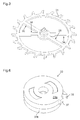
- This first embodiment relates to a direct exhaust with a constant force device comprising an exhaust mobile having two exhaust wheels pivotally connected together by a spiral spring.
- This high-amplitude escapement mechanism comprises an escape wheel comprising a lower escape wheel 30 and a wheel upper exhaust 31, an anchor 32 and an oscillator mobile 33 fixed on the axis of an oscillator, typically a balance spring.
- the lower escapement wheel 30 is pivoted on a platen with one movement and has a first pin 30a and a second pin 30b.
- the upper escapement wheel 31 is pivoted coaxially on the lower escape wheel 30 and has radii defining stop planes 34 and 35.
- the anchor 32 has an axis, a lower anchor 32a having an input pallet E and an output pallet S located at different levels.
- the entry pallet E has on its outer side a first rest plane 11 connected to an end face 10 by a rest formation which is preferably formed of a second rest plane 12 and a third rest plane 13 intersecting on a line of rest 14.
- the output pallet S has on its inner side a first rest plane 16 connected to a rest formation which is still preferably formed of a second rest plane 17 and a third rest plane 18 intersecting one another. rest line 19.
- the entry pallet E is at the same level as the lower escape wheel 30 and cooperates with it while the output pallet S is at the level of the upper escape wheel 31 and cooperates with it. .
- the anchor 32 further comprises an upper anchor 32b whose end comprises a fork with four teeth 36a, 36b, 36c, 36d.
- the oscillator wheel 33 is composed of two plates, a release plate 33a, which is at the same level as the upper anchor 32b and which has a pin 37, and a pulse plate 33b, which is at the same level. level that the upper escape wheel 31, which comprises a pulse plane 38 cooperating with the teeth of the upper exhaust wheel 31.
- a spiral spring of constant force (not illustrated not to overload the drawing) whose end is fixed on one of the pins 30a or 30b of the wheel lower exhaust 30 and the other end is attached to the axis of the upper exhaust wheel 31 connects the two exhaust wheels 30 and 31.
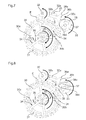
- the anchor 32 bears on a first fixed abutment 20.
- the orientation of the first rest plane 11 of the entry pallet E causes the anchor 32 to tend to turn counterclockwise.
- This first release phase lasts until the tooth ds of the upper escape wheel 31 leaves the first rest plane 11 of the entry pallet E and passes on its second rest plane 12.
- the torque of the gear train movement and spring of constant force causes the anchor 32 in the clockwise direction through the orientation of the second rest plane 12 of the input pallet E.
- the contact between the ankle 37 and the upper anchor 32b is broken . ( Fig.9 )
- the upper escapement wheel 31 comes into contact with the line of rest 14 separating the second rest plane 12 and the third rest plane 13 from the pallet between E. At this moment the upper exhaust wheels 31 and lower 30 are blocked by the entry pallet E respectively by the pins 30a, 30b of the lower escape wheel 30 and the stop planes 34, 35 of the upper escape wheel 31.
- the anchor is replaced in this second balance position by the escape wheels.
- the pendulum is free.
- the exhaust mechanism is in its second equilibrium position ( Fig. 10 ).
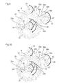
- the tooth of the upper escape wheel 31 leaves the third rest plane 13 of the entry pallet E. At this moment the upper and lower exhaust wheels 31 and 30 are free to turn clockwise.
- the anchor 32 continues to rotate clockwise, the ankle 37 escapes the tooth 36c of the anchor and the balance is free again.
- the upper escapement wheel 31 is no longer locked and rotates clockwise thanks to the constant force spring.
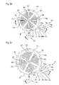
- the lower escapement wheel 30 comes into contact with the third rest plane 18 of the output pallet S ( Fig. 12 ).
- the pins 30a and 30b of the lower escapement wheel 30 leave the stop planes 34, 35 of the upper escapement wheel 31. This second phase of release lasts until a tooth ds of the wheel d upper exhaust 31 comes into contact with the pulse plane 38 of the impulse plate 33b ( Fig. 13 ).
- the fourth equilibrium position is maintained until the pin 37 comes into contact with the tooth 36a of the upper anchor 32b.
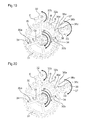
- the rocker wheel 33 causes the anchor 32 in the anti-clockwise direction slightly lowering the lower escape wheel 30 and thus the upper exhaust wheel 31 via the pins 30a, 30b of the lower exhaust wheel in support with the stop plane 35 of the upper escapement wheel 31 ( Fig. 18 )
- This fourth release phase lasts until the tooth di of the lower escape wheel 30 leaves the first rest plane 16 of the output pallet S and passes on the second rest plane 17 of this output pallet S ( Fig. 19 ). At this moment it is the torque of the gear train which drives the anchor 32 in the anti-clockwise direction thanks to the orientation of the second rest plane 16 of the output pallet S. The contact between the ankle 37 and the tooth 36a of the upper anchor 32a is broken and the escape mechanism is then in its fourth equilibrium position ( Fig. 20 ). The balance is free again. This fourth equilibrium position is the same as the third equilibrium position ( Fig. 14 ) except that the pendulum rotates clockwise.
- This fifth release phase lasts until the tooth di of the lower escape wheel 30 leaves the third rest plane 18 of the output pallet S. At this moment the two upper and lower 31 exhaust wheels 30 are free to turn clockwise.
- the anchor 32 continues to turn anti-clockwise and the balance is free again.
- the upper escape wheel 31 comes via one of its teeth ds in contact with the third rest plane 13 of the entry pallet E. This tooth ds will be placed on the line of rest 14 of the entry pallet E under the effect of the couple the work train and the orientation of the second 12 and third 13 resting planes of the entry pallet E positioning the anchor 32 so that the balance is free again.
- the lower exhaust wheel 30 is no longer locked and rotates clockwise thanks to the torque of the gear train.
- the contact between the pins 30a, 30b of the lower escapement wheel 30 and the stop plane 34 of the upper escapement wheel 31 is lost.
- the spring of constant force connecting the lower escape wheel 30 is reloaded. at the upper escapement wheel 31 ( Fig. 22 ).
- This fifth release phase lasts until the pins 30a, 30b of the lower escapement wheel 30 come into contact with the stop plane 35 of the upper escapement wheel 31 ( Fig. 23 ).
- the rocker arm drives the anchor wheel 32 in the anti-clockwise direction by slightly pushing back the upper escape wheel 31 and thus the lower escape wheel 30 via the pins 30a, 30b and the stop plane 35 ( Fig. 24 )
- This sixth release phase lasts until the tooth ds of the upper escapement wheel 31 leaves the second rest plane 12 of the entry pallet E and passes on the first rest plane 11 of this pallet.
- the torque of the cog and the constant force spring causes the anchor 32 in the counterclockwise direction, thanks to the orientation of the first rest plane 11 of the input pallet E.
- the contact between the pin 37 of the movable balance wheel 33 is broken with the upper anchor.
- This sixth phase of release lasts until the anchor 32 comes into contact with the first fixed stop 20. We find our in the first equilibrium position ( Fig. 7 ) and the cycle can start again.
- the special feature of this escapement mechanism is to allow balance phases where the balance can continue its alternation by oscillating the anchor without releasing the escape wheels. This is achieved thanks to the juxtaposition of several rest formations and notably thanks to the presence an additional rest formation on the pallets, which allows the balance to perform several turns for each alternation while the pulse is given only once per alternation when the anchor is moved sufficiently to release the mobile exhaust.
- the entry and exit pallets S have second and third rest planes which form a concave rest formation, for example V-shaped (or U-shaped), but other shapes are also possible, even a flat shape.
- the entry pallet E and the output pallet S of the anchor comprises a first rest plane and at least one additional rest formation, adjacent to the first rest plane.
- this formation is concave and formed of a second plane of rest and a third plane of rest forming a V between them and defining by their intersection a line of rest.
- the anchor If the anchor is slightly displaced during an impact, for example, it does not leave its equilibrium position but automatically returns to its position defined by the tooth of the mobile escapement coming into contact with the line of rest of the formation concave rest is the intersection between the second rest plane and the third rest plane.
- such an escapement mechanism also comprises an anchor whose end cooperating with the peg of the balance wheel comprises at least four teeth and not a simple fork with two teeth.
- each entry and exit pallet E has a concave, generally V-shaped rest formation formed by a second rest plane and a third rest plane whose intersection forms a line of rest.
- Each pallet, input E and output S also has a first rest plane located on the outer edge respectively internal to the pallet and adjoining the concave rest formation, usually V-shaped.
- the four teeth of the upper anchor cooperating with the peg of the balance wheel can all be identical since none of them serves to give the impulse to the pendulum.
- the pendulum performs several turns, usually two to three turns, alternately.
- a pulse is delivered to the pulse plane by the escapement mobile directly for each alternation of the balance.
- the peg cooperates with the teeth of the fork of the anchor to oscillate it and let pass said pin but without causing the release of the mobile escape which, under the effect of the gear, puts the anchor in a position of equilibrium when the pulse is not delivered to the balance.
- the concave, generally U-shaped or preferably V-shaped form of the rest formation formed by the first 11; 16 and second 12; 17 rest planes of the entry and exit pallets E and S the orientation of these planes with respect to the axis of rotation of the anchor cause that under the effect of the torque provided by the wheelhouse, the escapement wheel returns the anchor in equilibrium position when the latter is slightly shifted in one direction or the other, for example following a shock
- the passage of the equilibrium position on the first plane of rest 11, 16 of the input pallet E respectively output S to the equilibrium position on the formation of rest 14, 19 of these entry pallets E and exit S is achieved by an oscillation of the anchor 32 caused by the balance wheel, acting on the fork of the anchor and therefore by the energy of the pendulum.
- This oscillation of the anchor allows the balance to perform several turns for each alternation of these oscillations while causing the release of the escapement mobile only once by alternating the pendulum.
- the anchor drives the anchor 47 in the anti-clockwise direction by the tooth 49a of the fork 48.
- the mobile The exhaust lasts a slight step backwards, this phase lasts until the tooth of the upper escape wheel 44 is completely clear of the entry pallet E. It should be noted that before the entry pallet E the exit pallet S is completely unobstructed and is placed on the path of a tooth of the lower escape wheel 40.
- This impulse phase lasts until the lower escapement wheel comes into abutment against the upper escapement wheel 44 by its pins 45 coming into contact with the ends of the notches 43 of the lower escapement wheel 40 ( figure 35 ).
- the upper escapement wheel 44 abuts against the lower escapement wheel 40 via the studs 45 and the ends of the notches 43.
- the torque of the constant force spring 46 keeps the upper escapement wheel 44 abutting on the wheel lower exhaust 40.
- the ankle 53 comes into contact with the tooth 49b of the fork 48 of the anchor 47 and causes anchor clockwise. This is the second phase of release ( figure 36 ).
- the escapement mobile undergoes a slight decline.
- This second release phase lasts until the tooth of the lower escapement wheel 40 is completely cleared from the output pallet S of the anchor 47. Note that before the output pallet S is cleared , the entry pallet E of the anchor is placed on the path of a tooth of the upper escapement wheel 44.
- the torque applied by the finishing gear of the movement to the lower escapement wheel 40 being greater than the torque of the constant force spring 46 thus makes it possible to drive in rotation the upper escapement wheel 44 causing the spring of constant force to be recharged. 46.
- This phase of recharging the constant force lasts until the lower escape wheel 40 abuts against the upper escape wheel 44 via the pins 45 and the end faces of the notches 43.
- the escape mechanism has returned to the initial equilibrium position and a new cycle can begin again.
- This exhaust mechanism has an anti-shock device.
- the dart 50 comes into contact with the cylindrical rim 54 of the stinger plate 51 c preventing the release of the exhaust wheels 40, 44.
- the dart 50 is placed sometimes inside the cylindrical rim 54 (preventing the rotation of the anchor in the clockwise direction) sometimes outside the cylindrical rim 54 (preventing rotation of the anchor counterclockwise).
- the opening 54a in the cylindrical rim 54 of the stinger plate 51c allows the displacement of the anchor during the operating phases of the exhaust mechanism.
- the first embodiment also allows the oscillator to operate at an amplitude greater than 360 ° to the detriment of part of its performance.
Landscapes
- Physics & Mathematics (AREA)
- General Physics & Mathematics (AREA)
- Mechanical Operated Clutches (AREA)
Priority Applications (1)
| Application Number | Priority Date | Filing Date | Title |
|---|---|---|---|
| EP15177689.5A EP3121661B1 (de) | 2015-07-21 | 2015-07-21 | Direkter uhrhemmungsmechanismus mit konstanter kraft |
Applications Claiming Priority (1)
| Application Number | Priority Date | Filing Date | Title |
|---|---|---|---|
| EP15177689.5A EP3121661B1 (de) | 2015-07-21 | 2015-07-21 | Direkter uhrhemmungsmechanismus mit konstanter kraft |
Publications (2)
| Publication Number | Publication Date |
|---|---|
| EP3121661A1 true EP3121661A1 (de) | 2017-01-25 |
| EP3121661B1 EP3121661B1 (de) | 2018-05-23 |
Family
ID=53682587
Family Applications (1)
| Application Number | Title | Priority Date | Filing Date |
|---|---|---|---|
| EP15177689.5A Active EP3121661B1 (de) | 2015-07-21 | 2015-07-21 | Direkter uhrhemmungsmechanismus mit konstanter kraft |
Country Status (1)
| Country | Link |
|---|---|
| EP (1) | EP3121661B1 (de) |
Cited By (5)
| Publication number | Priority date | Publication date | Assignee | Title |
|---|---|---|---|---|
| CN106707718A (zh) * | 2017-03-01 | 2017-05-24 | 谭泽华 | 钟表分轴冲击擒纵器 |
| PL423844A1 (pl) * | 2017-12-11 | 2019-06-17 | Grzegorz Szychliński | Zespół wychwytu zegara wahadłowego |
| WO2020015889A1 (de) * | 2018-07-20 | 2020-01-23 | Creaditive Ag | Hemmungssystem und das hemmungssystem umfassendes messgerät |
| US20210141340A1 (en) * | 2018-07-02 | 2021-05-13 | Complitime Sa | Timepiece escapement mechanism |
| US11397408B2 (en) | 2018-05-25 | 2022-07-26 | Société Anonyme de la Manufacture d'Horlogerie Audemars Piguet & Cie | Automatically starting and secured detent escapement for a timepiece |
Citations (5)
| Publication number | Priority date | Publication date | Assignee | Title |
|---|---|---|---|---|
| DE178113C (de) * | ||||
| CH223109A (fr) * | 1941-10-01 | 1942-08-31 | Theurillat Xavier | Dispositif d'échappement dit à force constante pour mouvements d'horlogerie, compteurs, etc. |
| FR1009853A (fr) * | 1948-07-02 | 1952-06-04 | Mécanisme d'échappement perfectionné | |
| US2970427A (en) | 1957-03-28 | 1961-02-07 | Gen Time Corp | Constant torque escapement |
| CH353679A (fr) | 1959-03-24 | 1961-04-15 | Theurillat Xavier | Echappement dit à force constante |
-
2015
- 2015-07-21 EP EP15177689.5A patent/EP3121661B1/de active Active
Patent Citations (5)
| Publication number | Priority date | Publication date | Assignee | Title |
|---|---|---|---|---|
| DE178113C (de) * | ||||
| CH223109A (fr) * | 1941-10-01 | 1942-08-31 | Theurillat Xavier | Dispositif d'échappement dit à force constante pour mouvements d'horlogerie, compteurs, etc. |
| FR1009853A (fr) * | 1948-07-02 | 1952-06-04 | Mécanisme d'échappement perfectionné | |
| US2970427A (en) | 1957-03-28 | 1961-02-07 | Gen Time Corp | Constant torque escapement |
| CH353679A (fr) | 1959-03-24 | 1961-04-15 | Theurillat Xavier | Echappement dit à force constante |
Cited By (12)
| Publication number | Priority date | Publication date | Assignee | Title |
|---|---|---|---|---|
| CN106707718A (zh) * | 2017-03-01 | 2017-05-24 | 谭泽华 | 钟表分轴冲击擒纵器 |
| CN106707718B (zh) * | 2017-03-01 | 2019-01-29 | 谭泽华 | 钟表分轴冲击擒纵器 |
| PL423844A1 (pl) * | 2017-12-11 | 2019-06-17 | Grzegorz Szychliński | Zespół wychwytu zegara wahadłowego |
| PL234149B1 (pl) * | 2017-12-11 | 2020-01-31 | Drozdziewicz Slawomir | Zespół wychwytu zegara wahadłowego |
| US11397408B2 (en) | 2018-05-25 | 2022-07-26 | Société Anonyme de la Manufacture d'Horlogerie Audemars Piguet & Cie | Automatically starting and secured detent escapement for a timepiece |
| US20210141340A1 (en) * | 2018-07-02 | 2021-05-13 | Complitime Sa | Timepiece escapement mechanism |
| US11988993B2 (en) * | 2018-07-02 | 2024-05-21 | Complitime Sa | Timepiece escapement mechanism |
| WO2020015889A1 (de) * | 2018-07-20 | 2020-01-23 | Creaditive Ag | Hemmungssystem und das hemmungssystem umfassendes messgerät |
| US20210286320A1 (en) * | 2018-07-20 | 2021-09-16 | Creaditive Ag | Escapement system and measuring device comprising said escapement system |
| JP2021531479A (ja) * | 2018-07-20 | 2021-11-18 | クレアディティヴ・アーゲー | 脱進機システム及びこれを備える測定装置 |
| JP7441835B2 (ja) | 2018-07-20 | 2024-03-01 | クレアディティヴ・アーゲー | 脱進機システム及びこれを備える測定装置 |
| US12032334B2 (en) * | 2018-07-20 | 2024-07-09 | Creaditive Ag | Escapement system and measuring device comprising said escapement system |
Also Published As
| Publication number | Publication date |
|---|---|
| EP3121661B1 (de) | 2018-05-23 |
Similar Documents
| Publication | Publication Date | Title |
|---|---|---|
| EP3121661B1 (de) | Direkter uhrhemmungsmechanismus mit konstanter kraft | |
| EP2645189B1 (de) | Flexibler Uhrhemmungsmechanismus | |
| EP2487546B1 (de) | Zweiachsige Hochleistungshemmung | |
| WO2009118310A1 (fr) | Mécanisme d'échappement | |
| EP3070537A1 (de) | Zeitbasiseinheit, die eine hemmung mit direktimpuls und konstanter kraft umfasst | |
| EP2407830A1 (de) | Uhr | |
| EP2607968B1 (de) | Uhrhemmungsmechanismus | |
| CH714200B1 (fr) | Dispositif d'échappement pour mouvement de montre mécanique comportant un échappement avec deux mobiles d'échappement. | |
| CH701921A2 (fr) | Echappement à ancre et pièce d'horlogerie comportant un tel échappement. | |
| EP3570117A1 (de) | Hemmungsmechanismus für uhr | |
| EP3781994B1 (de) | Restanker-hemmungmechanismus und uhrzeit mit einem solchen hemmungmechanismus | |
| CH713530B1 (fr) | Echappement, mouvement de pièce d'horlogerie et pièce d'horlogerie. | |
| EP3599514B1 (de) | Hemmungsmechanismus mit bistabilen und monostabilen federn | |
| EP3293583A1 (de) | Hemmungsmechanismus | |
| EP3475765B1 (de) | Uhrwerkshemmung | |
| EP3781993B1 (de) | Frei direkthemmung mechanismus für uhren. | |
| CH712288A1 (fr) | Dard bi-fonctionnel, dispositif de verrouillage et de sécurisation pour pièce d'horlogerie, et échappement horloger. | |
| CH712807B1 (fr) | Mécanisme d'échappement. | |
| EP1837718B1 (de) | Hemmungsvorrichtung für Uhrwerke | |
| WO2015004336A2 (fr) | Echappement pour pièce d'horlogerie avec tourbillon sans cage | |
| CH703442B1 (fr) | Pièce d'horlogerie comprenant au moins un organe réglant et un échappement relié à deux sources d'energie. | |
| CH704784B1 (fr) | Echappement à ancre comprenant deux roues d'échappement. | |
| EP4250019A1 (de) | Uhr-oszillator für ein ultraflaches uhrwerk | |
| EP4303664A1 (de) | Uhrwerk und uhr, die ein solches uhrwerk umfasst | |
| CH713800B1 (fr) | Mécanisme horloger comprenant un mécanisme d'échappement à ancre et un organe régulateur oscillant. |
Legal Events
| Date | Code | Title | Description |
|---|---|---|---|
| PUAI | Public reference made under article 153(3) epc to a published international application that has entered the european phase |
Free format text: ORIGINAL CODE: 0009012 |
|
| AK | Designated contracting states |
Kind code of ref document: A1 Designated state(s): AL AT BE BG CH CY CZ DE DK EE ES FI FR GB GR HR HU IE IS IT LI LT LU LV MC MK MT NL NO PL PT RO RS SE SI SK SM TR |
|
| AX | Request for extension of the european patent |
Extension state: BA ME |
|
| 17P | Request for examination filed |
Effective date: 20170720 |
|
| RBV | Designated contracting states (corrected) |
Designated state(s): AL AT BE BG CH CY CZ DE DK EE ES FI FR GB GR HR HU IE IS IT LI LT LU LV MC MK MT NL NO PL PT RO RS SE SI SK SM TR |
|
| GRAP | Despatch of communication of intention to grant a patent |
Free format text: ORIGINAL CODE: EPIDOSNIGR1 |
|
| INTG | Intention to grant announced |
Effective date: 20180102 |
|
| GRAS | Grant fee paid |
Free format text: ORIGINAL CODE: EPIDOSNIGR3 |
|
| GRAA | (expected) grant |
Free format text: ORIGINAL CODE: 0009210 |
|
| AK | Designated contracting states |
Kind code of ref document: B1 Designated state(s): AL AT BE BG CH CY CZ DE DK EE ES FI FR GB GR HR HU IE IS IT LI LT LU LV MC MK MT NL NO PL PT RO RS SE SI SK SM TR |
|
| REG | Reference to a national code |
Ref country code: GB Ref legal event code: FG4D Free format text: NOT ENGLISH |
|
| REG | Reference to a national code |
Ref country code: CH Ref legal event code: EP Ref country code: CH Ref legal event code: NV Representative=s name: MICHELI AND CIE SA, CH |
|
| REG | Reference to a national code |
Ref country code: IE Ref legal event code: FG4D Free format text: LANGUAGE OF EP DOCUMENT: FRENCH |
|
| REG | Reference to a national code |
Ref country code: AT Ref legal event code: REF Ref document number: 1001999 Country of ref document: AT Kind code of ref document: T Effective date: 20180615 |
|
| REG | Reference to a national code |
Ref country code: DE Ref legal event code: R096 Ref document number: 602015011359 Country of ref document: DE |
|
| REG | Reference to a national code |
Ref country code: FR Ref legal event code: PLFP Year of fee payment: 4 |
|
| REG | Reference to a national code |
Ref country code: NL Ref legal event code: MP Effective date: 20180523 |
|
| REG | Reference to a national code |
Ref country code: LT Ref legal event code: MG4D |
|
| PG25 | Lapsed in a contracting state [announced via postgrant information from national office to epo] |
Ref country code: NO Free format text: LAPSE BECAUSE OF FAILURE TO SUBMIT A TRANSLATION OF THE DESCRIPTION OR TO PAY THE FEE WITHIN THE PRESCRIBED TIME-LIMIT Effective date: 20180823 Ref country code: FI Free format text: LAPSE BECAUSE OF FAILURE TO SUBMIT A TRANSLATION OF THE DESCRIPTION OR TO PAY THE FEE WITHIN THE PRESCRIBED TIME-LIMIT Effective date: 20180523 Ref country code: BG Free format text: LAPSE BECAUSE OF FAILURE TO SUBMIT A TRANSLATION OF THE DESCRIPTION OR TO PAY THE FEE WITHIN THE PRESCRIBED TIME-LIMIT Effective date: 20180823 Ref country code: SE Free format text: LAPSE BECAUSE OF FAILURE TO SUBMIT A TRANSLATION OF THE DESCRIPTION OR TO PAY THE FEE WITHIN THE PRESCRIBED TIME-LIMIT Effective date: 20180523 Ref country code: ES Free format text: LAPSE BECAUSE OF FAILURE TO SUBMIT A TRANSLATION OF THE DESCRIPTION OR TO PAY THE FEE WITHIN THE PRESCRIBED TIME-LIMIT Effective date: 20180523 Ref country code: LT Free format text: LAPSE BECAUSE OF FAILURE TO SUBMIT A TRANSLATION OF THE DESCRIPTION OR TO PAY THE FEE WITHIN THE PRESCRIBED TIME-LIMIT Effective date: 20180523 |
|
| PG25 | Lapsed in a contracting state [announced via postgrant information from national office to epo] |
Ref country code: HR Free format text: LAPSE BECAUSE OF FAILURE TO SUBMIT A TRANSLATION OF THE DESCRIPTION OR TO PAY THE FEE WITHIN THE PRESCRIBED TIME-LIMIT Effective date: 20180523 Ref country code: NL Free format text: LAPSE BECAUSE OF FAILURE TO SUBMIT A TRANSLATION OF THE DESCRIPTION OR TO PAY THE FEE WITHIN THE PRESCRIBED TIME-LIMIT Effective date: 20180523 Ref country code: LV Free format text: LAPSE BECAUSE OF FAILURE TO SUBMIT A TRANSLATION OF THE DESCRIPTION OR TO PAY THE FEE WITHIN THE PRESCRIBED TIME-LIMIT Effective date: 20180523 Ref country code: GR Free format text: LAPSE BECAUSE OF FAILURE TO SUBMIT A TRANSLATION OF THE DESCRIPTION OR TO PAY THE FEE WITHIN THE PRESCRIBED TIME-LIMIT Effective date: 20180824 Ref country code: RS Free format text: LAPSE BECAUSE OF FAILURE TO SUBMIT A TRANSLATION OF THE DESCRIPTION OR TO PAY THE FEE WITHIN THE PRESCRIBED TIME-LIMIT Effective date: 20180523 |
|
| REG | Reference to a national code |
Ref country code: AT Ref legal event code: MK05 Ref document number: 1001999 Country of ref document: AT Kind code of ref document: T Effective date: 20180523 |
|
| PG25 | Lapsed in a contracting state [announced via postgrant information from national office to epo] |
Ref country code: EE Free format text: LAPSE BECAUSE OF FAILURE TO SUBMIT A TRANSLATION OF THE DESCRIPTION OR TO PAY THE FEE WITHIN THE PRESCRIBED TIME-LIMIT Effective date: 20180523 Ref country code: PL Free format text: LAPSE BECAUSE OF FAILURE TO SUBMIT A TRANSLATION OF THE DESCRIPTION OR TO PAY THE FEE WITHIN THE PRESCRIBED TIME-LIMIT Effective date: 20180523 Ref country code: DK Free format text: LAPSE BECAUSE OF FAILURE TO SUBMIT A TRANSLATION OF THE DESCRIPTION OR TO PAY THE FEE WITHIN THE PRESCRIBED TIME-LIMIT Effective date: 20180523 Ref country code: CZ Free format text: LAPSE BECAUSE OF FAILURE TO SUBMIT A TRANSLATION OF THE DESCRIPTION OR TO PAY THE FEE WITHIN THE PRESCRIBED TIME-LIMIT Effective date: 20180523 Ref country code: AT Free format text: LAPSE BECAUSE OF FAILURE TO SUBMIT A TRANSLATION OF THE DESCRIPTION OR TO PAY THE FEE WITHIN THE PRESCRIBED TIME-LIMIT Effective date: 20180523 Ref country code: RO Free format text: LAPSE BECAUSE OF FAILURE TO SUBMIT A TRANSLATION OF THE DESCRIPTION OR TO PAY THE FEE WITHIN THE PRESCRIBED TIME-LIMIT Effective date: 20180523 Ref country code: SK Free format text: LAPSE BECAUSE OF FAILURE TO SUBMIT A TRANSLATION OF THE DESCRIPTION OR TO PAY THE FEE WITHIN THE PRESCRIBED TIME-LIMIT Effective date: 20180523 |
|
| REG | Reference to a national code |
Ref country code: DE Ref legal event code: R097 Ref document number: 602015011359 Country of ref document: DE |
|
| PG25 | Lapsed in a contracting state [announced via postgrant information from national office to epo] |
Ref country code: SM Free format text: LAPSE BECAUSE OF FAILURE TO SUBMIT A TRANSLATION OF THE DESCRIPTION OR TO PAY THE FEE WITHIN THE PRESCRIBED TIME-LIMIT Effective date: 20180523 Ref country code: IT Free format text: LAPSE BECAUSE OF FAILURE TO SUBMIT A TRANSLATION OF THE DESCRIPTION OR TO PAY THE FEE WITHIN THE PRESCRIBED TIME-LIMIT Effective date: 20180523 |
|
| PG25 | Lapsed in a contracting state [announced via postgrant information from national office to epo] |
Ref country code: LU Free format text: LAPSE BECAUSE OF NON-PAYMENT OF DUE FEES Effective date: 20180721 Ref country code: MC Free format text: LAPSE BECAUSE OF FAILURE TO SUBMIT A TRANSLATION OF THE DESCRIPTION OR TO PAY THE FEE WITHIN THE PRESCRIBED TIME-LIMIT Effective date: 20180523 |
|
| PLBE | No opposition filed within time limit |
Free format text: ORIGINAL CODE: 0009261 |
|
| STAA | Information on the status of an ep patent application or granted ep patent |
Free format text: STATUS: NO OPPOSITION FILED WITHIN TIME LIMIT |
|
| REG | Reference to a national code |
Ref country code: BE Ref legal event code: MM Effective date: 20180731 |
|
| REG | Reference to a national code |
Ref country code: IE Ref legal event code: MM4A |
|
| PG25 | Lapsed in a contracting state [announced via postgrant information from national office to epo] |
Ref country code: IE Free format text: LAPSE BECAUSE OF NON-PAYMENT OF DUE FEES Effective date: 20180721 |
|
| 26N | No opposition filed |
Effective date: 20190226 |
|
| PG25 | Lapsed in a contracting state [announced via postgrant information from national office to epo] |
Ref country code: BE Free format text: LAPSE BECAUSE OF NON-PAYMENT OF DUE FEES Effective date: 20180731 Ref country code: SI Free format text: LAPSE BECAUSE OF FAILURE TO SUBMIT A TRANSLATION OF THE DESCRIPTION OR TO PAY THE FEE WITHIN THE PRESCRIBED TIME-LIMIT Effective date: 20180523 |
|
| PGFP | Annual fee paid to national office [announced via postgrant information from national office to epo] |
Ref country code: DE Payment date: 20190719 Year of fee payment: 5 Ref country code: FR Payment date: 20190719 Year of fee payment: 5 |
|
| PG25 | Lapsed in a contracting state [announced via postgrant information from national office to epo] |
Ref country code: AL Free format text: LAPSE BECAUSE OF FAILURE TO SUBMIT A TRANSLATION OF THE DESCRIPTION OR TO PAY THE FEE WITHIN THE PRESCRIBED TIME-LIMIT Effective date: 20180523 |
|
| PGFP | Annual fee paid to national office [announced via postgrant information from national office to epo] |
Ref country code: GB Payment date: 20190719 Year of fee payment: 5 |
|
| PG25 | Lapsed in a contracting state [announced via postgrant information from national office to epo] |
Ref country code: MT Free format text: LAPSE BECAUSE OF FAILURE TO SUBMIT A TRANSLATION OF THE DESCRIPTION OR TO PAY THE FEE WITHIN THE PRESCRIBED TIME-LIMIT Effective date: 20180523 |
|
| PG25 | Lapsed in a contracting state [announced via postgrant information from national office to epo] |
Ref country code: TR Free format text: LAPSE BECAUSE OF FAILURE TO SUBMIT A TRANSLATION OF THE DESCRIPTION OR TO PAY THE FEE WITHIN THE PRESCRIBED TIME-LIMIT Effective date: 20180523 |
|
| PG25 | Lapsed in a contracting state [announced via postgrant information from national office to epo] |
Ref country code: PT Free format text: LAPSE BECAUSE OF FAILURE TO SUBMIT A TRANSLATION OF THE DESCRIPTION OR TO PAY THE FEE WITHIN THE PRESCRIBED TIME-LIMIT Effective date: 20180523 |
|
| PG25 | Lapsed in a contracting state [announced via postgrant information from national office to epo] |
Ref country code: MK Free format text: LAPSE BECAUSE OF NON-PAYMENT OF DUE FEES Effective date: 20180523 Ref country code: CY Free format text: LAPSE BECAUSE OF FAILURE TO SUBMIT A TRANSLATION OF THE DESCRIPTION OR TO PAY THE FEE WITHIN THE PRESCRIBED TIME-LIMIT Effective date: 20180523 Ref country code: HU Free format text: LAPSE BECAUSE OF FAILURE TO SUBMIT A TRANSLATION OF THE DESCRIPTION OR TO PAY THE FEE WITHIN THE PRESCRIBED TIME-LIMIT; INVALID AB INITIO Effective date: 20150721 |
|
| PG25 | Lapsed in a contracting state [announced via postgrant information from national office to epo] |
Ref country code: IS Free format text: LAPSE BECAUSE OF FAILURE TO SUBMIT A TRANSLATION OF THE DESCRIPTION OR TO PAY THE FEE WITHIN THE PRESCRIBED TIME-LIMIT Effective date: 20180923 |
|
| REG | Reference to a national code |
Ref country code: DE Ref legal event code: R119 Ref document number: 602015011359 Country of ref document: DE |
|
| GBPC | Gb: european patent ceased through non-payment of renewal fee |
Effective date: 20200721 |
|
| PG25 | Lapsed in a contracting state [announced via postgrant information from national office to epo] |
Ref country code: FR Free format text: LAPSE BECAUSE OF NON-PAYMENT OF DUE FEES Effective date: 20200731 Ref country code: GB Free format text: LAPSE BECAUSE OF NON-PAYMENT OF DUE FEES Effective date: 20200721 |
|
| PG25 | Lapsed in a contracting state [announced via postgrant information from national office to epo] |
Ref country code: DE Free format text: LAPSE BECAUSE OF NON-PAYMENT OF DUE FEES Effective date: 20210202 |
|
| PGFP | Annual fee paid to national office [announced via postgrant information from national office to epo] |
Ref country code: CH Payment date: 20240801 Year of fee payment: 10 |